US7382804B2 - Bandwidth efficient system and method for ranging nodes in a wireless communication network - Google Patents
Bandwidth efficient system and method for ranging nodes in a wireless communication networkDownload PDFInfo
- Publication number
- US7382804B2 US7382804B2US11/197,950US19795005AUS7382804B2US 7382804 B2US7382804 B2US 7382804B2US 19795005 AUS19795005 AUS 19795005AUS 7382804 B2US7382804 B2US 7382804B2
- Authority
- US
- United States
- Prior art keywords
- node
- messages
- nodes
- neighboring nodes
- received
- Prior art date
- Legal status (The legal status is an assumption and is not a legal conclusion. Google has not performed a legal analysis and makes no representation as to the accuracy of the status listed.)
- Active, expires
Links
Images


Classifications
- H—ELECTRICITY
- H04—ELECTRIC COMMUNICATION TECHNIQUE
- H04W—WIRELESS COMMUNICATION NETWORKS
- H04W64/00—Locating users or terminals or network equipment for network management purposes, e.g. mobility management
- G—PHYSICS
- G01—MEASURING; TESTING
- G01S—RADIO DIRECTION-FINDING; RADIO NAVIGATION; DETERMINING DISTANCE OR VELOCITY BY USE OF RADIO WAVES; LOCATING OR PRESENCE-DETECTING BY USE OF THE REFLECTION OR RERADIATION OF RADIO WAVES; ANALOGOUS ARRANGEMENTS USING OTHER WAVES
- G01S11/00—Systems for determining distance or velocity not using reflection or reradiation
- G01S11/02—Systems for determining distance or velocity not using reflection or reradiation using radio waves
- G—PHYSICS
- G01—MEASURING; TESTING
- G01S—RADIO DIRECTION-FINDING; RADIO NAVIGATION; DETERMINING DISTANCE OR VELOCITY BY USE OF RADIO WAVES; LOCATING OR PRESENCE-DETECTING BY USE OF THE REFLECTION OR RERADIATION OF RADIO WAVES; ANALOGOUS ARRANGEMENTS USING OTHER WAVES
- G01S3/00—Direction-finders for determining the direction from which infrasonic, sonic, ultrasonic, or electromagnetic waves, or particle emission, not having a directional significance, are being received
- G01S3/02—Direction-finders for determining the direction from which infrasonic, sonic, ultrasonic, or electromagnetic waves, or particle emission, not having a directional significance, are being received using radio waves
- G—PHYSICS
- G01—MEASURING; TESTING
- G01S—RADIO DIRECTION-FINDING; RADIO NAVIGATION; DETERMINING DISTANCE OR VELOCITY BY USE OF RADIO WAVES; LOCATING OR PRESENCE-DETECTING BY USE OF THE REFLECTION OR RERADIATION OF RADIO WAVES; ANALOGOUS ARRANGEMENTS USING OTHER WAVES
- G01S5/00—Position-fixing by co-ordinating two or more direction or position line determinations; Position-fixing by co-ordinating two or more distance determinations
- G01S5/02—Position-fixing by co-ordinating two or more direction or position line determinations; Position-fixing by co-ordinating two or more distance determinations using radio waves
- G01S5/0284—Relative positioning
- G01S5/0289—Relative positioning of multiple transceivers, e.g. in ad hoc networks
- H—ELECTRICITY
- H04—ELECTRIC COMMUNICATION TECHNIQUE
- H04L—TRANSMISSION OF DIGITAL INFORMATION, e.g. TELEGRAPHIC COMMUNICATION
- H04L41/00—Arrangements for maintenance, administration or management of data switching networks, e.g. of packet switching networks
- H04L41/12—Discovery or management of network topologies
- H—ELECTRICITY
- H04—ELECTRIC COMMUNICATION TECHNIQUE
- H04B—TRANSMISSION
- H04B17/00—Monitoring; Testing
- H04B17/20—Monitoring; Testing of receivers
- H04B17/27—Monitoring; Testing of receivers for locating or positioning the transmitter
- H—ELECTRICITY
- H04—ELECTRIC COMMUNICATION TECHNIQUE
- H04W—WIRELESS COMMUNICATION NETWORKS
- H04W84/00—Network topologies
- H04W84/18—Self-organising networks, e.g. ad-hoc networks or sensor networks
Definitions
- the present inventionrelates to a bandwidth efficient system and method for measuring the distance between nodes in a wireless network, in particular, a wireless network of unsynchronized nodes with one-way data transfer, and for computing the relative and the absolute location of the wireless nodes using the measured distances. More particularly, the present invention relates to a bandwidth efficient system and method for ranging nodes in any wireless network, such as a multihopping ad-hoc network, using radio communications and measuring the time of arrival (TOA) of data packets at the nodes, and further computing the geographic coordinates of fixed reference nodes.
- TOAtime of arrival
- each mobile nodeis capable of operating as a base station or router for the other mobile nodes, thus eliminating the need for a fixed infrastructure of base stations.
- network nodestransmit and receive data packet communications in a multiplexed format, such as time-division multiple access (TDMA) format, code-division multiple access (CDMA) format, or frequency-division multiple access (FDMA) format.
- TDMAtime-division multiple access
- CDMAcode-division multiple access
- FDMAfrequency-division multiple access
- More sophisticated ad-hoc networksare also being developed which, in addition to enabling mobile nodes to communicate with each other as in a conventional ad-hoc network, further enable the mobile nodes to access fixed networks and thus communicate with fixed nodes, such as those on the public switched telephone network (PSTN), and on other networks such as the Internet. Details of these advanced types of ad-hoc networks are described in U.S. Pat. No. 7,072,650 entitled “Ad Hoc Peer-to-Peer Mobile Radio Access System Interfaced to the PSTN and Cellular Networks”, granted on Jul. 4, 2006, in U.S. Pat. No.
- the time of flightis the time interval during which a radio signal travels from one wireless terminal to another wireless terminal. Multiplying the TOF with the speed of radio wave propagation provides the distance or “range” between the two terminals.
- the range itselfis used in several applications. Since the range provides only a measurement of proximity, one range alone is very seldom used in applications. For computing the position of a mobile node, most of the applications use either a set of ranges between several terminals, or one range and additional information about the direction.
- the TOFis computed using two-way or one-way ranging.
- the station that needs the rangetransmits a request for range evaluation to a reference station.
- the reference stationanswers the request instantly or after a known delay.
- the time between transmitting the request and receiving the response at the first stationis two times the TOF since in two-way ranging, the station seeking the range initiates the dialog.
- one-way rangingclock synchronization of all references (i.e., terminals or nodes) is required all the time. If the clock of a mobile terminal involved in the ranging also is synchronized with the references, the measured ranges are true, otherwise they are all affected by the same unknown error and are called pseudo-ranges.
- one-way rangingis a more bandwidth efficient method than two-way ranging, the process of synchronizing references does require two-way exchange of messages, thereby consuming bandwidth.
- 2n ranging messagesare transmitted, while with one-way ranging, only n+1 messages are transmitted, and from time to time, another 2n messages are transmitted for maintaining the synchronization between the clocks of the terminals.
- GPSglobal positioning system
- All GPS satelliteshave high precision synchronized clocks and geocentric ephemeredes.
- the mobilereceives simultaneously signals from several satellites located above the horizon and computes its geocentric position.
- the methodcan be used only in places where several satellites can be seen simultaneously.
- Very accurate precision of locationcan be achieved only with very sophisticated GPS equipment that remains immobile for some long time and can receive signals from a large number satellites.
- the methodcannot be used because the number of received signals from satellites is not satisfactory.
- TDOAtime difference of arrival
- the mobile transmits a signalat least three synchronized base stations receive the signal and record the time of arrival (TOA) of the signal. Then these base stations transmit the TOA of the mobile signal to a central computing unit usually through a wired connection.
- the computing unitwhich knows the geocentric position of each base station, computes the geocentric position of the mobile using the TDOA of signals by solving the intersection of hyperbolas.
- the main advantage of the methodis that no change has to be made to the mobile telephone for enabling the operation.
- the drawback of the methodconsists in potentially limited propagation of the signal between the mobile phone to at least three base stations when the mobile is located on narrow streets with tall buildings, inside large buildings or underground.
- FIG. 1is a block diagram of an example ad-hoc wireless communications network including a plurality of nodes employing a system and method in accordance with an embodiment of the present invention
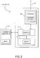
- FIG. 2is a block diagram illustrating an example of a mobile node employed in the network shown in FIG. 1 ;
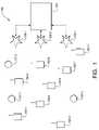
- FIG. 3is a block diagram illustrating an example of three nodes of the wireless network shown in FIG. 1 operating in accordance with an embodiment of the present invention.
- FIG. 4is a graph illustrating an example of the relationship between clocks of the nodes shown in FIG. 3 .
- embodiments of the invention described hereinmay be comprised of one or more conventional processors and unique stored program instructions that control the one or more processors to implement, in conjunction with certain non-processor circuits, some, most, or all of the functions of a bandwidth efficient system and method for measuring the distance between terminals in a wireless network described herein.
- the non-processor circuitsmay include, but are not limited to, a radio receiver, a radio transmitter, signal drivers, clock circuits, power source circuits, and user input devices. As such, these functions may be interpreted as steps of a method to perform a bandwidth efficient technique for measuring the distance between terminals in a wireless network.
- the present inventionprovides an efficient system and method for ranging nodes in a wireless communications network, such as a multihopping ad-hoc peer-to-peer network.
- the networkcomprises a plurality of mobile wireless nodes, with each node periodically transmitting a respective digital message that contains information regarding its respective neighboring nodes from which any prior digital messages have been received.
- the nodesalso receive digital messages from other nodes in the network.
- the information regarding neighboring nodes from which prior digital messages have been receivedincludes the times of arrival of those messages and the positions of the neighboring nodes transmitting the messages at the time when these messages were transmitted, if such positions are known.
- the information in these messagesis used by a node receiving the messages to range the nodes from which the node received the messages.
- the system and methodthus measures the range between nodes in a wireless communications network using one-way data transfer between nodes. Using this technique, only n messages need to be transmitted to compute n 2 ranges in the network, with no restriction regarding the mobility of any node in the network.
- FIG. 1is a block diagram illustrating an example of an ad-hoc packet-switched wireless communications network 100 employing an embodiment of the present invention.
- the network 100includes a plurality of mobile wireless user terminals 102 - 1 through 102 - n (referred to generally as nodes 102 or mobile nodes 102 ), and can, but is not required to, include a fixed network 104 having a plurality of access points 106 - 1 , 106 - 2 , . . . 106 - n (referred to generally as nodes 106 or access points 106 ), for providing nodes 102 with access to the fixed network 104 .
- the fixed network 104can include, for example, a core local access network (LAN), and a plurality of servers and gateway routers to provide network nodes with access to other networks, such as other ad-hoc networks, the public switched telephone network (PSTN) and the Internet.
- the network 100further can include a plurality of fixed routers 107 - 1 through 107 - n (referred to generally as nodes 107 or fixed routers 107 ) for routing data packets between other nodes 102 , 106 or 107 . It is noted that for purposes of this discussion, the nodes discussed above can be collectively referred to as “nodes 102 , 106 and 107 ”, or simply “nodes” or “terminals”.
- the nodes 102 , 106 and 107are capable of communicating with each other directly, or via one or more other nodes 102 , 106 or 107 operating as a router or routers for packets being sent between nodes, as described in U.S. Pat. Nos. 7,072,650, 6,807,165 and 6,873,839 referenced above.
- each node 102 , 106 and 107includes a transceiver, or modem 108 , which is coupled to an antenna 110 and is capable of receiving and transmitting signals, such as packetized signals, to and from the node 102 , 106 or 107 , under the control of a controller 112 .
- the packetized data signalscan include, for example, voice, data or multimedia information, and packetized control signals, including node update information.
- Each node 102 , 106 and 107further includes a memory 114 , such as a random access memory (RAM) that is capable of storing, among other things, routing information pertaining to itself and other nodes in the network 100 .
- a memory 114such as a random access memory (RAM) that is capable of storing, among other things, routing information pertaining to itself and other nodes in the network 100 .
- certain nodes, especially mobile nodes 102can include a host 116 which may consist of any number of devices, such as a notebook computer terminal, mobile telephone unit, mobile data unit, or any other suitable device.
- Each node 102 , 106 and 107also includes the appropriate hardware and software to perform Internet Protocol (IP) and Address Resolution Protocol (ARP), the purposes of which can be readily appreciated by one skilled in the art.
- IPInternet Protocol
- ARPAddress Resolution Protocol
- the appropriate hardware and software to perform transmission control protocol (TCP) and user datagram protocol (UDP)may also be included.
- the bandwidth efficient ranging system and methodthat will now be described in detail are applicable to wireless digital communication systems, especially to ad-hoc multihopping networks.
- nodes 102are mobile, and continuously exchange information about the network structure. It assures that data packets are correctly routed across the network from the source to the destination, following a multihopping path.
- Each node or terminal 102includes a register that is incremented periodically and is called “the terminal clock”.
- the registercan be included in the controller 112 and/or in the hardware associated with the controller 112 .
- terminal timeor “node time” refers to the value recorded in the clock register at a particular moment. Because the clocks are not synchronized, all clock registers show different values all the time. When the clock register is full, its content returns to zero. It means that each terminal shows time zero at a periodic rate.
- each node 102transmits a digital message periodically (e.g., when the terminal clock register is zero). All neighbor nodes 102 receiving the message record the respective time of arrival (TOA), that is, each node 102 receiving the message records the content of the clock register at receiving time.
- TOAtime of arrival
- the TOA recorded by all nodes 102 receiving the same messageare all different because node clocks are not synchronized. Also, because the clocks are not synchronized, it is expected that the signals from all network nodes 102 are spread across the clock interval and do not interfere.
- the digital message transmitted at the beginning of the clock intervalcontains the identification about all neighbor nodes 102 from where messages have been received, the TOA of those messages and the position of the node transmitting the message, if the position is known.
- the precision of TOAis very important, and methods for improving the TOA quality are described in U.S. Patent Application Publication No. 2003/0227895 and U.S. Pat. No. 6,137,441, the entire content of both being incorporated herein by reference.
- a node 102 operating in the n node networkcan compute its own position and the positions of all other terminals in the network 100 as will now be described.
- the technique used in accordance with an embodiment of the present inventionwill be described in a simplified example with three nodes (e.g., nodes 102 ) only as shown in FIG. 3 .
- the techniqueis applicable to any size network as would be evident to one of ordinary skill in the art.
- FIG. 3has three nodes 102 identified as nodes A, B, and C, that transmit the ranging message every ⁇ seconds.
- the respective distances between the nodesare d AB , d BC and d AC corresponding to propagation times p AB , p BC and p AC .
- ⁇ BAt B ⁇ t A
- ⁇ CAt C ⁇ t A
- ⁇ ABt A ⁇ t B
- ACt A ⁇ t C
- node BWhen the clock on node B is zero, node B transmits its message. At that moment the clock at node A shows the time ⁇ BA while the clock at node C shows the time ⁇ CA + ⁇ BA . The message transmitted by node B is received at node A at time ⁇ BA +p AB and at node C at time ⁇ CA + ⁇ BA +p BC
- node CWhen node C transmits its message, the clock at node A shows time ⁇ CA and the clock at node B shows ⁇ BA + ⁇ CA .
- the clock of node Ashows time ⁇ CA +p AC while the clock at node B shows ⁇ BA + ⁇ CA +p BC .
- node Ahas the following information received from messages transmitted by other nodes or measured locally:
- n AB , n AC , n BA , n BC , n CA and n CBare the content of the clock registers of each node when receiving the corresponding message and are either measured by a particular (such as values n BA and n CA which are measured by node A) or received with the messages transmitted by the other nodes.
- p ABn AB + n BA - ⁇ 2
- p ACn AC + n CA - ⁇ 2
- the oscillators of each node 102which provide the clock tick, do not have exactly the same frequency on all nodes 102 . This means that if the clock cycle ⁇ is too large, the measured TOA could be affected by errors.
- the most common oscillatorhas a frequency error of 2 ppm, which means that the node clock could slip 2 ⁇ s every second.
- the clock drift errorshould be smaller than 3 ns. The result is that, for assuring an error smaller than 3 ns caused by a 2 ppm oscillator, the clock cycle must be not larger than 3 ms.
- Each node in the networktherefore has to transmit one message during each clock cycle. Depending upon the burst throughput of each node, the condition could be difficult to achieve if the number of nodes is too large.
- the TOA of a messageis identified by correlating a sequence of pseudorandom bits.
- QPSKQuadrature Phase Shift Keying
- two pseudorandom sequencescan be used simultaneously for increasing the precision of TOA measurement.
- specific methodscan use the variation of the correlation function for improving the precision of TOA measurement.
- An example of such methodis presented in United States Patent Application Publication No. 20030227895 entitled “System and method for improving the accuracy of time of arrival measurements in a wireless ad-hoc communications network”, the entire content of which is incorporated herein by reference.
- phase shift of the received carrier signalis measured before and after receiving the pseudorandom sequence for identifying the drift of the oscillator clock of the node receiving the signal in relation with the frequency of the received signal.
- a nodeWhen a node transmits the message with the TOA of messages received from neighbors, it also transmits the information about the relative drift of its own clock in reference with all neighbor clocks.
- the node performing the computation of the locationapplies the drift correction according with clock corrections as presented in Table 2.
- ⁇ ABis the drift of clock B in relation with clock A
- ⁇ BAis the drift of clock A in relation with clock B, and so on.
- the second eventhappens ⁇ BA seconds after the first event.
- the timeis measured by the clock on node B, which controls the event execution. Because the clock on node A runs faster (or slower) than the clock on node B, when the second event happens, the clock on node A shows the time ( ⁇ BA )(1+ ⁇ BA ) In similar mode, the clock on node C advances between the two events with ( ⁇ BA )(1+ ⁇ BC ).
- the third eventhappens ⁇ CA seconds after the first event or ⁇ ( ⁇ CA +( ⁇ BA )(1+ ⁇ BC )) seconds after the second event.
- These time intervalsare measured by the clock running on node C that controls the transmission.
- the clock on node Ashows ( ⁇ CA )(1+ ⁇ CA ) while the clock on node B shows ( ⁇ ( ⁇ CA +( ⁇ BA ) (1+ ⁇ BC )))(1+ ⁇ CB )
- the propagation timeis the time the signal travels from one node to the next.
- the propagation timeis measured with clocks running on each node. Since these clocks do not have the same pace, it is expected that each clock provides a measurement different than the other two.
- the node A clockis considered the reference for notation purposes, meaning that the propagation time measured by clock A as p AB is measured by the clock B as p AB (1+ ⁇ AB ).
- the propagation times of signals received at Aare correct because they are timed with the “correct clock,” but all other propagation times have to be corrected.
- the resultis that the starting time of the event needs correction with the drift between the clock controlling the event and the clock receiving the signal, while the propagation time should be corrected with the drift between the node receiving the signal and the node A that is performing the computation.
- the values n AB , n AC , n BA and so onare the TOA measured by each node, so they are known numbers.
- the ⁇ AB , ⁇ AC , ⁇ BC and so onare also measured by each node when the message is received.
- the only unknown variablesare the propagation times p AB , p BC and PAC and the clock shifts ⁇ BA and ⁇ CA . They can be easily computed from the linear equations from Table 2.
- the values ⁇ BA and ⁇ CAare the clock shifts when the transmission from A happened (at time zero for node A). Because these clocks have different paces, the clock shift between any two nodes changes continuously. Therefore, these equations provide the values of the unknown variables at time zero not at the time when data was collected. The technique thus allows for precise computation of clock shifts and propagation times regardless of the length of the clock cycle ⁇ and the precision of oscillators controlling the clock ticks and the transmit frequency.
- the clock at node Ahas been considered as a reference. Any node in the network can perform the same computation by considering itself as a reference (or as node A).
- the drift of the reference node in relation with the standard secondhas an effect of incorrect computation of the distance associated with the propagation time of the radio signal.
- the expected erroris about 10 ⁇ 6 m per meter, or 0.001 m per km.
- the relative speed of the nodes 102is identified by each node via the drift of clock frequencies. When the nodes are moving apart, each node 102 sees the other node clock running slower than it really does. When the nodes 102 are approaching each other, each node 102 sees the other one running at a higher frequency than it really does.
- these techniquescan be used in wireless digital networks with or without multi-hopping capabilities.
- multihopping capabilitiesare generally needed for transmitting the geographical coordinates of fixed references.
- similar resultscan be obtained while using beacon identifiable signals instead of digital messages for collecting the TOA or range information.
Landscapes
- Engineering & Computer Science (AREA)
- Computer Networks & Wireless Communication (AREA)
- Signal Processing (AREA)
- Physics & Mathematics (AREA)
- General Physics & Mathematics (AREA)
- Radar, Positioning & Navigation (AREA)
- Remote Sensing (AREA)
- Mobile Radio Communication Systems (AREA)
Abstract
Description
ΔBA=tB−tA
ΔCA=tC−tA
ΔAB=tA−tB
ΔAC=tA−tC
ΔBC=tB−tC
ΔCB=tC−tB
ΔBA=τ−ΔAB
ΔCA=τ−ΔAC
ΔBC=τ−ΔCB
ΔAB+ΔBC=ΔAC
ΔBC+ΔCA=ΔBA
ΔCA+ΔAB=ΔCB
| TABLE 1 | |||
| Node A | Node B | Node C | |
| A | ηAB= ΔBA+ ρAB | ηAC= ΔCA+ ρAC | |
| B | ηBA= τ − ΔBA+ ρAB | ηBC= ΔCA+ τ − | |
| ΔBA+ ρBC | |||
| C | ηCA= τ − ΔCA+ ρAC | ηCB= ΔBA+ τ − ΔCA+ | |
| ρBC | |||
| TABLE 2 | |||
| Event | Node A | Node B | Node C |
| A | ηAB= ΔBA+ ρAB | ηAC= ΔCA+ | |
| (1 + δAB) | ρAC(1 + δAC) | ||
| B | ηBA= ρAB+ | ηBC= ρBC(1 + | |
| (τ− ΔBA) | δAC) + | ||
| (1 + δBA) | ΔCA+ (τ − ΔBA) | ||
| (1 + δCB) | |||
| C | ηCA= ρAC+ | ηCB= ρBC(1 + δAB) + | |
| (τ− ΔCA) | (τ − (ΔCA+ (τ − ΔBA) | ||
| (1 + δCA) | (1 + δBC)))(1 + δCB) | ||
| First Event | Node A | Node | Node C | ||
| 0 | ΔBA | ΔCA | |||
| Second | |||
| Event | Node A | Node B | Node C |
| (τ − ΔBA)(1 + δBA) | 0 or τ | ΔCA+ (τ − ΔBA)(1 + δBC) | |
| Third | |||
| Event | Node A | Node B | Node C |
| (τ − ΔCA)(1 + δCA) | (τ − (ΔCA+ (τ − ΔBA)(1 + δBC))) | 0 or τ | |
| (1 + δCB) | |||
Claims (21)
Priority Applications (1)
| Application Number | Priority Date | Filing Date | Title |
|---|---|---|---|
| US11/197,950US7382804B2 (en) | 2004-08-05 | 2005-08-05 | Bandwidth efficient system and method for ranging nodes in a wireless communication network |
Applications Claiming Priority (2)
| Application Number | Priority Date | Filing Date | Title |
|---|---|---|---|
| US59882804P | 2004-08-05 | 2004-08-05 | |
| US11/197,950US7382804B2 (en) | 2004-08-05 | 2005-08-05 | Bandwidth efficient system and method for ranging nodes in a wireless communication network |
Publications (2)
| Publication Number | Publication Date |
|---|---|
| US20060029009A1 US20060029009A1 (en) | 2006-02-09 |
| US7382804B2true US7382804B2 (en) | 2008-06-03 |
Family
ID=35839928
Family Applications (1)
| Application Number | Title | Priority Date | Filing Date |
|---|---|---|---|
| US11/197,950Active2026-08-10US7382804B2 (en) | 2004-08-05 | 2005-08-05 | Bandwidth efficient system and method for ranging nodes in a wireless communication network |
Country Status (4)
| Country | Link |
|---|---|
| US (1) | US7382804B2 (en) |
| KR (2) | KR20090014387A (en) |
| DE (1) | DE112005001916T5 (en) |
| WO (1) | WO2006017699A2 (en) |
Cited By (10)
| Publication number | Priority date | Publication date | Assignee | Title |
|---|---|---|---|---|
| US20080157957A1 (en)* | 2005-03-11 | 2008-07-03 | Koninklijke Philips Electronics, N.V. | Wall Finding For Wireless Lighting Assignment |
| US20090028092A1 (en)* | 2007-07-13 | 2009-01-29 | Michael Rothschild | Method and a system for determining the spatial location of nodes in a wireless network |
| US20090213828A1 (en)* | 2006-12-07 | 2009-08-27 | Zulutime, Llc | Wireless local area network-based position locating systems and methods |
| US20090233621A1 (en)* | 2006-12-07 | 2009-09-17 | Zulutime, Llc | Systems and methods for locating a mobile device within a cellular system |
| US20100266003A1 (en)* | 2009-03-19 | 2010-10-21 | Lucila Patino-Studencka | Method and Apparatus for Estimating Clock Deviations, for Virtual Synchronization of Free-Running Clocks and for Determining the Position of a Movable Object |
| WO2012166015A3 (en)* | 2011-05-24 | 2013-03-28 | Эртээл - Сервис Лимитед | Method and means for locating a radio centre |
| US8463290B2 (en) | 2010-07-09 | 2013-06-11 | Digimarc Corporation | Mobile device positioning in dynamic groupings of communication devices |
| US8717919B2 (en) | 2009-02-12 | 2014-05-06 | Digimarc Corporation | Systems and methods for space-time determinations with reduced network traffic |
| US9282471B2 (en) | 2012-03-21 | 2016-03-08 | Digimarc Corporation | Positioning systems for wireless networks |
| US10591581B2 (en) | 2006-12-07 | 2020-03-17 | Digimarc Corporation | Space-time calibration system and method |
Families Citing this family (17)
| Publication number | Priority date | Publication date | Assignee | Title |
|---|---|---|---|---|
| US7923550B2 (en) | 2003-04-14 | 2011-04-12 | Xiaolian Gao | Reagent compounds and methods of making and using the same |
| WO2006017696A2 (en)* | 2004-08-05 | 2006-02-16 | Meshnetworks, Inc. | Autonomous reference system and method for monitoring the location and movement of objects |
| US7843862B2 (en)* | 2006-05-18 | 2010-11-30 | Encore Software Limited | Adhoc networking |
| GB2442515B (en)* | 2006-10-06 | 2010-01-13 | Motorola Inc | Communication system and method of operation therefor |
| US7295159B1 (en) | 2006-10-26 | 2007-11-13 | Motorola, Inc. | Method for measuring time of arrival of signals in a communications network |
| KR101040254B1 (en)* | 2008-07-11 | 2011-06-09 | 광주과학기술원 | Location Estimation Method and System Using Unidirectional Measurement Technique |
| US20100136999A1 (en)* | 2008-12-03 | 2010-06-03 | Electronics And Telecommunications Research Institute | Apparatus and method for determining position of terminal |
| KR101162407B1 (en) | 2008-12-15 | 2012-07-04 | 한국전자통신연구원 | Multi pan conflict resolution method in zigbee |
| US9060342B2 (en)* | 2011-04-04 | 2015-06-16 | Saab Sensis Corporation | System and method for passively determining own position listening to wireless time synchronization communications |
| KR101390722B1 (en)* | 2012-10-31 | 2014-04-30 | 숭실대학교산학협력단 | Wireless localization method using fingerprinting localization algorithms and apparatus thereof |
| US10942250B2 (en)* | 2014-03-03 | 2021-03-09 | Rosemount Inc. | Positioning system |
| US11102746B2 (en) | 2014-03-03 | 2021-08-24 | Rosemount Inc. | Positioning system |
| US10948566B1 (en)* | 2015-01-23 | 2021-03-16 | Oceanit Laboratories, Inc. | GPS-alternative method to perform asynchronous positioning of networked nodes |
| BE1023698B1 (en)* | 2016-04-08 | 2017-06-16 | Nouveaux Etablissements Charles Martin SA | QUICK DISTANCE MEASUREMENT METHOD APPLIED TO POSITIONING |
| BR112018072990A2 (en)* | 2016-05-12 | 2019-02-26 | Rosemount Inc. | positioning system, and method of determining a position of an active tag. |
| CN111279725A (en) | 2018-09-17 | 2020-06-12 | 罗斯蒙特公司 | location awareness system |
| US12408005B2 (en)* | 2022-05-31 | 2025-09-02 | Cisco Technology, Inc. | Differentiated time-difference of arrival for ultra-wideband (UWB) |
Citations (24)
| Publication number | Priority date | Publication date | Assignee | Title |
|---|---|---|---|---|
| US3934251A (en) | 1974-11-07 | 1976-01-20 | The Bendix Corporation | Automatic t0 control for use in airborne DME system |
| US3943509A (en) | 1972-03-09 | 1976-03-09 | Elliott Brothers (London) Limited | Navigation aiding systems with one-way ranging and two-way synchronization |
| US4161730A (en) | 1977-10-17 | 1979-07-17 | General Electric Company | Radio determination using satellites transmitting timing signals with correction by active range measurement |
| US4161734A (en) | 1977-10-17 | 1979-07-17 | General Electric Company | Position surveillance using one active ranging satellite and time of arrival of a signal from an independent satellite |
| US4357609A (en) | 1980-08-25 | 1982-11-02 | Sperry Corporation | Noncoherent two way ranging apparatus |
| US5321668A (en) | 1990-02-21 | 1994-06-14 | The Laitram Corporation | Hydroacoustic ranging method using bottom reflections |
| US6137441A (en) | 1998-09-09 | 2000-10-24 | Qualcomm Incorporated | Accurate range and range rate determination in a satellite communications system |
| US6208297B1 (en) | 1998-10-09 | 2001-03-27 | Cell-Loc Inc. | Methods and apparatus to position a mobile receiver using downlink signals, part I |
| US6266014B1 (en) | 1998-10-09 | 2001-07-24 | Cell-Loc Inc. | Methods and apparatus to position a mobile receiver using downlink signals part IV |
| US20020058502A1 (en) | 2000-11-13 | 2002-05-16 | Peter Stanforth | Ad hoc peer-to-peer mobile radio access system interfaced to the PSTN and cellular networks |
| US6453168B1 (en) | 1999-08-02 | 2002-09-17 | Itt Manufacturing Enterprises, Inc | Method and apparatus for determining the position of a mobile communication device using low accuracy clocks |
| US20030189906A1 (en) | 2002-03-15 | 2003-10-09 | Belcea John M. | System and method for providing adaptive control of transmit power and data rate in an ad-hoc communication network |
| US20030227895A1 (en) | 2002-06-05 | 2003-12-11 | Strutt Guenael T. | System and method for improving the accuracy of time of arrival measurements in a wireless ad-hoc communications network |
| US6728545B1 (en) | 2001-11-16 | 2004-04-27 | Meshnetworks, Inc. | System and method for computing the location of a mobile terminal in a wireless communications network |
| US6807165B2 (en) | 2000-11-08 | 2004-10-19 | Meshnetworks, Inc. | Time division protocol for an ad-hoc, peer-to-peer radio network having coordinating channel access to shared parallel data channels with separate reservation channel |
| US20040246975A1 (en) | 2003-06-06 | 2004-12-09 | Meshnetworks, Inc. | System and method to improve the overall performance of a wireless communication network |
| US6873839B2 (en) | 2000-11-13 | 2005-03-29 | Meshnetworks, Inc. | Prioritized-routing for an ad-hoc, peer-to-peer, mobile radio access system |
| US20060014547A1 (en)* | 2004-07-13 | 2006-01-19 | Sbc Knowledge Ventures, L.P. | System and method for location based policy management |
| US20060029010A1 (en) | 2004-08-05 | 2006-02-09 | Meshnetworks, Inc. | Autonomous reference system and method for monitoring the location and movement of objects |
| US7042867B2 (en)* | 2002-07-29 | 2006-05-09 | Meshnetworks, Inc. | System and method for determining physical location of a node in a wireless network during an authentication check of the node |
| US7085576B2 (en)* | 2002-12-30 | 2006-08-01 | Motorola, Inc. | Method and apparatus for providing streaming information to a wireless mobile wireless device |
| US7126951B2 (en)* | 2003-06-06 | 2006-10-24 | Meshnetworks, Inc. | System and method for identifying the floor number where a firefighter in need of help is located using received signal strength indicator and signal propagation time |
| US7142524B2 (en)* | 2002-05-01 | 2006-11-28 | Meshnetworks, Inc. | System and method for using an ad-hoc routing algorithm based on activity detection in an ad-hoc network |
| US7221686B1 (en)* | 2001-11-30 | 2007-05-22 | Meshnetworks, Inc. | System and method for computing the signal propagation time and the clock correction for mobile stations in a wireless network |
Family Cites Families (2)
| Publication number | Priority date | Publication date | Assignee | Title |
|---|---|---|---|---|
| US5469409A (en)* | 1994-03-14 | 1995-11-21 | Motorola, Inc. | Method for clock calibration in a position determination system |
| US20030152110A1 (en)* | 2002-02-08 | 2003-08-14 | Johan Rune | Synchronization of remote network nodes |
- 2005
- 2005-08-05DEDE112005001916Tpatent/DE112005001916T5/ennot_activeWithdrawn
- 2005-08-05USUS11/197,950patent/US7382804B2/enactiveActive
- 2005-08-05WOPCT/US2005/027816patent/WO2006017699A2/enactiveApplication Filing
- 2005-08-05KRKR1020087030766Apatent/KR20090014387A/ennot_activeWithdrawn
- 2005-08-05KRKR1020077005270Apatent/KR100890483B1/ennot_activeExpired - Lifetime
Patent Citations (25)
| Publication number | Priority date | Publication date | Assignee | Title |
|---|---|---|---|---|
| US3943509A (en) | 1972-03-09 | 1976-03-09 | Elliott Brothers (London) Limited | Navigation aiding systems with one-way ranging and two-way synchronization |
| US3934251A (en) | 1974-11-07 | 1976-01-20 | The Bendix Corporation | Automatic t0 control for use in airborne DME system |
| US4161730A (en) | 1977-10-17 | 1979-07-17 | General Electric Company | Radio determination using satellites transmitting timing signals with correction by active range measurement |
| US4161734A (en) | 1977-10-17 | 1979-07-17 | General Electric Company | Position surveillance using one active ranging satellite and time of arrival of a signal from an independent satellite |
| US4357609A (en) | 1980-08-25 | 1982-11-02 | Sperry Corporation | Noncoherent two way ranging apparatus |
| US5321668A (en) | 1990-02-21 | 1994-06-14 | The Laitram Corporation | Hydroacoustic ranging method using bottom reflections |
| US6137441A (en) | 1998-09-09 | 2000-10-24 | Qualcomm Incorporated | Accurate range and range rate determination in a satellite communications system |
| US6208297B1 (en) | 1998-10-09 | 2001-03-27 | Cell-Loc Inc. | Methods and apparatus to position a mobile receiver using downlink signals, part I |
| US6266014B1 (en) | 1998-10-09 | 2001-07-24 | Cell-Loc Inc. | Methods and apparatus to position a mobile receiver using downlink signals part IV |
| US6453168B1 (en) | 1999-08-02 | 2002-09-17 | Itt Manufacturing Enterprises, Inc | Method and apparatus for determining the position of a mobile communication device using low accuracy clocks |
| US6807165B2 (en) | 2000-11-08 | 2004-10-19 | Meshnetworks, Inc. | Time division protocol for an ad-hoc, peer-to-peer radio network having coordinating channel access to shared parallel data channels with separate reservation channel |
| US20020058502A1 (en) | 2000-11-13 | 2002-05-16 | Peter Stanforth | Ad hoc peer-to-peer mobile radio access system interfaced to the PSTN and cellular networks |
| US6873839B2 (en) | 2000-11-13 | 2005-03-29 | Meshnetworks, Inc. | Prioritized-routing for an ad-hoc, peer-to-peer, mobile radio access system |
| US6728545B1 (en) | 2001-11-16 | 2004-04-27 | Meshnetworks, Inc. | System and method for computing the location of a mobile terminal in a wireless communications network |
| US7221686B1 (en)* | 2001-11-30 | 2007-05-22 | Meshnetworks, Inc. | System and method for computing the signal propagation time and the clock correction for mobile stations in a wireless network |
| US20030189906A1 (en) | 2002-03-15 | 2003-10-09 | Belcea John M. | System and method for providing adaptive control of transmit power and data rate in an ad-hoc communication network |
| US6904021B2 (en) | 2002-03-15 | 2005-06-07 | Meshnetworks, Inc. | System and method for providing adaptive control of transmit power and data rate in an ad-hoc communication network |
| US7142524B2 (en)* | 2002-05-01 | 2006-11-28 | Meshnetworks, Inc. | System and method for using an ad-hoc routing algorithm based on activity detection in an ad-hoc network |
| US20030227895A1 (en) | 2002-06-05 | 2003-12-11 | Strutt Guenael T. | System and method for improving the accuracy of time of arrival measurements in a wireless ad-hoc communications network |
| US7042867B2 (en)* | 2002-07-29 | 2006-05-09 | Meshnetworks, Inc. | System and method for determining physical location of a node in a wireless network during an authentication check of the node |
| US7085576B2 (en)* | 2002-12-30 | 2006-08-01 | Motorola, Inc. | Method and apparatus for providing streaming information to a wireless mobile wireless device |
| US7126951B2 (en)* | 2003-06-06 | 2006-10-24 | Meshnetworks, Inc. | System and method for identifying the floor number where a firefighter in need of help is located using received signal strength indicator and signal propagation time |
| US20040246975A1 (en) | 2003-06-06 | 2004-12-09 | Meshnetworks, Inc. | System and method to improve the overall performance of a wireless communication network |
| US20060014547A1 (en)* | 2004-07-13 | 2006-01-19 | Sbc Knowledge Ventures, L.P. | System and method for location based policy management |
| US20060029010A1 (en) | 2004-08-05 | 2006-02-09 | Meshnetworks, Inc. | Autonomous reference system and method for monitoring the location and movement of objects |
Cited By (20)
| Publication number | Priority date | Publication date | Assignee | Title |
|---|---|---|---|---|
| US20080157957A1 (en)* | 2005-03-11 | 2008-07-03 | Koninklijke Philips Electronics, N.V. | Wall Finding For Wireless Lighting Assignment |
| US8451763B2 (en) | 2006-12-07 | 2013-05-28 | Digimarc Corporation | Wireless local area network-based position locating systems and methods |
| US20090213828A1 (en)* | 2006-12-07 | 2009-08-27 | Zulutime, Llc | Wireless local area network-based position locating systems and methods |
| US20090233621A1 (en)* | 2006-12-07 | 2009-09-17 | Zulutime, Llc | Systems and methods for locating a mobile device within a cellular system |
| US10591581B2 (en) | 2006-12-07 | 2020-03-17 | Digimarc Corporation | Space-time calibration system and method |
| US8421675B2 (en)* | 2006-12-07 | 2013-04-16 | Digimarc Corporation | Systems and methods for locating a mobile device within a cellular system |
| US9753115B2 (en) | 2006-12-07 | 2017-09-05 | Digimarc Corporation | Systems and methods for locating a mobile device within a cellular system |
| US9014162B2 (en) | 2006-12-07 | 2015-04-21 | Digimarc Corporation | Wireless local area network-based position locating systems and methods |
| US7974264B2 (en)* | 2007-07-13 | 2011-07-05 | Michael Rothschild | Method and a system for determining the spatial location of nodes in a wireless network |
| US20090028092A1 (en)* | 2007-07-13 | 2009-01-29 | Michael Rothschild | Method and a system for determining the spatial location of nodes in a wireless network |
| US8717919B2 (en) | 2009-02-12 | 2014-05-06 | Digimarc Corporation | Systems and methods for space-time determinations with reduced network traffic |
| US20100266003A1 (en)* | 2009-03-19 | 2010-10-21 | Lucila Patino-Studencka | Method and Apparatus for Estimating Clock Deviations, for Virtual Synchronization of Free-Running Clocks and for Determining the Position of a Movable Object |
| US8363768B2 (en)* | 2009-03-19 | 2013-01-29 | Fraunhofer-Gesellschaft Zur Foerderung Der Angewandten Forschung E.V. | Method and apparatus for estimating clock deviations, for virtual synchronization of free-running clocks and for determining the position of a movable object |
| US8463290B2 (en) | 2010-07-09 | 2013-06-11 | Digimarc Corporation | Mobile device positioning in dynamic groupings of communication devices |
| US9363783B2 (en) | 2010-07-09 | 2016-06-07 | Digimarc Corporation | Mobile device positioning in dynamic groupings of communication devices |
| US9049563B2 (en) | 2010-07-09 | 2015-06-02 | Digimarc Corporation | Mobile device positioning in dynamic groupings of communication devices |
| EA024885B1 (en)* | 2011-05-24 | 2016-10-31 | Эртээл - Сервис Лимитед | Method for locating a radio centre and means for locating a radio centre |
| WO2012166015A3 (en)* | 2011-05-24 | 2013-03-28 | Эртээл - Сервис Лимитед | Method and means for locating a radio centre |
| US9282471B2 (en) | 2012-03-21 | 2016-03-08 | Digimarc Corporation | Positioning systems for wireless networks |
| US9891307B2 (en) | 2012-03-21 | 2018-02-13 | Digimarc Corporation | Positioning systems for wireless networks |
Also Published As
| Publication number | Publication date |
|---|---|
| KR20070051301A (en) | 2007-05-17 |
| KR20090014387A (en) | 2009-02-10 |
| DE112005001916T5 (en) | 2007-09-13 |
| WO2006017699A3 (en) | 2006-07-06 |
| WO2006017699A2 (en) | 2006-02-16 |
| US20060029009A1 (en) | 2006-02-09 |
| KR100890483B1 (en) | 2009-03-26 |
Similar Documents
| Publication | Publication Date | Title |
|---|---|---|
| US7382804B2 (en) | Bandwidth efficient system and method for ranging nodes in a wireless communication network | |
| US20210219254A1 (en) | Time synchronization method and apparatus | |
| US7054126B2 (en) | System and method for improving the accuracy of time of arrival measurements in a wireless ad-hoc communications network | |
| US8965413B2 (en) | Locating a wireless local area network associated with a wireless wide area network | |
| US8335173B2 (en) | Inserting time of departure information in frames to support multi-channel location techniques | |
| US7295159B1 (en) | Method for measuring time of arrival of signals in a communications network | |
| EP1271178B1 (en) | Positioning system for digital telephone networks | |
| JP4810169B2 (en) | Method for synchronizing transmitter transmit clock and receiver receive clock in a wireless communication network | |
| US8687560B2 (en) | Unsynchronized time-of-flight-based wireless positioning system using network broadcasts | |
| JP2010515052A (en) | Portable repeatable geolocation of RF emitters | |
| US9877149B2 (en) | Assisted passive geo-location of a wireless local area network device | |
| CA2554336A1 (en) | Transfer of calibrated time information in a mobile terminal | |
| JP2010528495A (en) | Method for determining time variation in a mobile terminal | |
| EP1005773A1 (en) | Location system for digital mobile telephony | |
| US20230048739A1 (en) | Positioning in a wireless communication network | |
| US7593736B1 (en) | Positioning system for digital telephone networks | |
| Nagy et al. | Time-based localisation in unsynchronized wireless LAN for industrial automation systems | |
| WO2009020952A1 (en) | Method and apparatus for locating a mobile device without synchronizing base station clocks | |
| CN115706630B (en) | Direct link positioning method, device and user equipment | |
| US11061103B1 (en) | Navigation system, device and method using unsynchronized nodes | |
| US9693187B2 (en) | Geo-location of a WLAN device | |
| WO2024026695A1 (en) | Systems and methods for accuracy improvement for rtt-based positioning | |
| Mah et al. | Pinpoint time difference of arrival for unsynchronized 802.11 wireless cards | |
| WO2023130876A1 (en) | Positioning method and apparatus | |
| CN119521368A (en) | High-precision time synchronization method, system, device and medium for wireless environment |
Legal Events
| Date | Code | Title | Description |
|---|---|---|---|
| AS | Assignment | Owner name:MESHNETWORKS, INC., FLORIDA Free format text:ASSIGNMENT OF ASSIGNORS INTEREST;ASSIGNORS:ALAPURANEN, PERTTI O.;BELCEA, JOHN M.;LORENZO-LUACES, EDUARDO;REEL/FRAME:020526/0414 Effective date:20080213 | |
| STCF | Information on status: patent grant | Free format text:PATENTED CASE | |
| FPAY | Fee payment | Year of fee payment:4 | |
| FPAY | Fee payment | Year of fee payment:8 | |
| AS | Assignment | Owner name:ARRIS ENTERPRISES LLC, PENNSYLVANIA Free format text:ASSIGNMENT OF ASSIGNORS INTEREST;ASSIGNOR:MOTOROLA SOLUTIONS, INC.;REEL/FRAME:044806/0900 Effective date:20170830 | |
| AS | Assignment | Owner name:WILMINGTON TRUST, NATIONAL ASSOCIATION, AS COLLATE Free format text:PATENT SECURITY AGREEMENT;ASSIGNOR:ARRIS ENTERPRISES LLC;REEL/FRAME:049820/0495 Effective date:20190404 Owner name:JPMORGAN CHASE BANK, N.A., NEW YORK Free format text:TERM LOAN SECURITY AGREEMENT;ASSIGNORS:COMMSCOPE, INC. OF NORTH CAROLINA;COMMSCOPE TECHNOLOGIES LLC;ARRIS ENTERPRISES LLC;AND OTHERS;REEL/FRAME:049905/0504 Effective date:20190404 Owner name:JPMORGAN CHASE BANK, N.A., NEW YORK Free format text:ABL SECURITY AGREEMENT;ASSIGNORS:COMMSCOPE, INC. OF NORTH CAROLINA;COMMSCOPE TECHNOLOGIES LLC;ARRIS ENTERPRISES LLC;AND OTHERS;REEL/FRAME:049892/0396 Effective date:20190404 Owner name:WILMINGTON TRUST, NATIONAL ASSOCIATION, AS COLLATERAL AGENT, CONNECTICUT Free format text:PATENT SECURITY AGREEMENT;ASSIGNOR:ARRIS ENTERPRISES LLC;REEL/FRAME:049820/0495 Effective date:20190404 | |
| MAFP | Maintenance fee payment | Free format text:PAYMENT OF MAINTENANCE FEE, 12TH YEAR, LARGE ENTITY (ORIGINAL EVENT CODE: M1553); ENTITY STATUS OF PATENT OWNER: LARGE ENTITY Year of fee payment:12 | |
| AS | Assignment | Owner name:WILMINGTON TRUST, DELAWARE Free format text:SECURITY INTEREST;ASSIGNORS:ARRIS SOLUTIONS, INC.;ARRIS ENTERPRISES LLC;COMMSCOPE TECHNOLOGIES LLC;AND OTHERS;REEL/FRAME:060752/0001 Effective date:20211115 | |
| AS | Assignment | Owner name:ARRIS ENTERPRISES LLC, GEORGIA Free format text:MERGER;ASSIGNOR:MESHNETWORKS, INC.;REEL/FRAME:060978/0116 Effective date:20170831 | |
| AS | Assignment | Owner name:ARRIS ENTERPRISES LLC, PENNSYLVANIA Free format text:CORRECTIVE BY NULLIFICATION TO REMOVE INCORRECTLY RECORDED PROPERTY NUMBERS PREVIOUSLY RECORDED AT REEL 044806, FRAME 0900. ASSIGNOR HEREBY CONFIRMS THE ASSIGNMENT OF PATENT RIGHTS;ASSIGNOR:MOTOROLA SOLUTIONS, INC.;REEL/FRAME:061038/0692 Effective date:20170830 | |
| AS | Assignment | Owner name:APOLLO ADMINISTRATIVE AGENCY LLC, NEW YORK Free format text:SECURITY INTEREST;ASSIGNORS:ARRIS ENTERPRISES LLC;COMMSCOPE TECHNOLOGIES LLC;COMMSCOPE INC., OF NORTH CAROLINA;AND OTHERS;REEL/FRAME:069889/0114 Effective date:20241217 | |
| AS | Assignment | Owner name:RUCKUS WIRELESS, LLC (F/K/A RUCKUS WIRELESS, INC.), NORTH CAROLINA Free format text:RELEASE OF SECURITY INTEREST AT REEL/FRAME 049905/0504;ASSIGNOR:JPMORGAN CHASE BANK, N.A., AS COLLATERAL AGENT;REEL/FRAME:071477/0255 Effective date:20241217 Owner name:COMMSCOPE TECHNOLOGIES LLC, NORTH CAROLINA Free format text:RELEASE OF SECURITY INTEREST AT REEL/FRAME 049905/0504;ASSIGNOR:JPMORGAN CHASE BANK, N.A., AS COLLATERAL AGENT;REEL/FRAME:071477/0255 Effective date:20241217 Owner name:COMMSCOPE, INC. OF NORTH CAROLINA, NORTH CAROLINA Free format text:RELEASE OF SECURITY INTEREST AT REEL/FRAME 049905/0504;ASSIGNOR:JPMORGAN CHASE BANK, N.A., AS COLLATERAL AGENT;REEL/FRAME:071477/0255 Effective date:20241217 Owner name:ARRIS SOLUTIONS, INC., NORTH CAROLINA Free format text:RELEASE OF SECURITY INTEREST AT REEL/FRAME 049905/0504;ASSIGNOR:JPMORGAN CHASE BANK, N.A., AS COLLATERAL AGENT;REEL/FRAME:071477/0255 Effective date:20241217 Owner name:ARRIS TECHNOLOGY, INC., NORTH CAROLINA Free format text:RELEASE OF SECURITY INTEREST AT REEL/FRAME 049905/0504;ASSIGNOR:JPMORGAN CHASE BANK, N.A., AS COLLATERAL AGENT;REEL/FRAME:071477/0255 Effective date:20241217 Owner name:ARRIS ENTERPRISES LLC (F/K/A ARRIS ENTERPRISES, INC.), NORTH CAROLINA Free format text:RELEASE OF SECURITY INTEREST AT REEL/FRAME 049905/0504;ASSIGNOR:JPMORGAN CHASE BANK, N.A., AS COLLATERAL AGENT;REEL/FRAME:071477/0255 Effective date:20241217 |