US7382778B2 - Link layer emulation - Google Patents
Link layer emulationDownload PDFInfo
- Publication number
- US7382778B2 US7382778B2US10/751,719US75171904AUS7382778B2US 7382778 B2US7382778 B2US 7382778B2US 75171904 AUS75171904 AUS 75171904AUS 7382778 B2US7382778 B2US 7382778B2
- Authority
- US
- United States
- Prior art keywords
- address
- layer
- mac address
- gateway
- network
- Prior art date
- Legal status (The legal status is an assumption and is not a legal conclusion. Google has not performed a legal analysis and makes no representation as to the accuracy of the status listed.)
- Active, expires
Links
Images


Classifications
- H—ELECTRICITY
- H04—ELECTRIC COMMUNICATION TECHNIQUE
- H04L—TRANSMISSION OF DIGITAL INFORMATION, e.g. TELEGRAPHIC COMMUNICATION
- H04L61/00—Network arrangements, protocols or services for addressing or naming
- H04L61/09—Mapping addresses
- H04L61/10—Mapping addresses of different types
- H04L61/103—Mapping addresses of different types across network layers, e.g. resolution of network layer into physical layer addresses or address resolution protocol [ARP]
- H—ELECTRICITY
- H04—ELECTRIC COMMUNICATION TECHNIQUE
- H04L—TRANSMISSION OF DIGITAL INFORMATION, e.g. TELEGRAPHIC COMMUNICATION
- H04L61/00—Network arrangements, protocols or services for addressing or naming
- H04L61/09—Mapping addresses
- H04L61/25—Mapping addresses of the same type
- H04L61/2596—Translation of addresses of the same type other than IP, e.g. translation from MAC to MAC addresses
- H—ELECTRICITY
- H04—ELECTRIC COMMUNICATION TECHNIQUE
- H04L—TRANSMISSION OF DIGITAL INFORMATION, e.g. TELEGRAPHIC COMMUNICATION
- H04L2101/00—Indexing scheme associated with group H04L61/00
- H04L2101/60—Types of network addresses
- H04L2101/618—Details of network addresses
- H04L2101/622—Layer-2 addresses, e.g. medium access control [MAC] addresses
Definitions
- the inventionrelates generally to communication networks. More particularly, the invention relates to communication link layer emulation.
- Packet networkingis a form of data communication in which data packets are routed from a source device to a destination device. Packets can be networked directly between a source node and a destination node, or the packets can be relayed through a number of intermediate nodes.
- the packetsgenerally include a source address, a destination address and a payload.
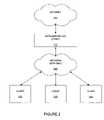
- FIG. 1shows a network device 110 connected to a network 100 .
- a client device 120can also be connected to the network 100 .
- the network device 110is a layer two (OSI model) device and the network 100 includes layer two routers. With the network 100 including only layer two devices, the network 100 appears to the network device 110 to be a transparent bridge. That is, if the network only includes layer two devices, then any client 120 connected to the network 100 , appears to the network device 110 , to be directly connected to the network device 110 .
- OSI modelOSI model
- a layer two device and layer two networkstransparently bridge data packets without altering MAC or IP header fields of the data packets, whereas layer three devices generally alter MAC header fields of data packets passing through the layer three devices.
- the altering of MAC headers of data packetscan present problems when interfacing a layer two device with a layer three network.
- the network deviceshould perceive a client connected to the network, to be connected directly to the network device.
- the inventionincludes an apparatus and method for emulating a layer two network.
- An embodiment of the inventionincludes a network of at least one router.
- the networkincludes a data packet address translator.
- the data packet address translatormanipulates address information of data packets routed by the network, so that a network device connected to the network perceives the network to be a bridge.
- One embodiment of the networkincludes wireless mesh network that is wirelessly connectable to a client.
- FIG. 1shows a network device connected to a client through a network.
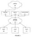
- FIG. 2shows network device connected to clients through a network of routers, according to an embodiment of the invention.
- FIG. 3shows network devices connected to clients through a network of routers, according to another embodiment of the invention.
- FIG. 4is shows a network that includes a gateway and access nodes, according to an embodiment of the invention.
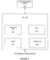
- FIG. 5shows one example of a gateway according to an embodiment of the invention.
- FIG. 6an upstream data path.
- FIG. 7shows a downstream data path.
- FIG. 8shows one example of a sequence of events for manipulating a MAC address of a downstream data packet.
- FIG. 9shows one example of a sequence of events for manipulating a MAC address of an upstream data packet.
- FIG. 10shows one example of a sequence of events for executing a pseudo proxy ARP.
- the inventionis embodied in link layer emulation. More specifically, the invention can include emulating a layer two network, so that a network device connected to a layer three network, perceives that layer three network as a transparent bridge.
- FIG. 2shows one example of a network device 210 connected to clients 220 , 222 , 224 through a network 230 of routers.
- the network 230includes a MAC (media access control) address translator (MAT).
- the MAT of the network 230provides manipulation of data packet addresses so that layer three routers of the network appear to the network device to be layer two devices.
- the network 230appears to the network device 210 to be a transparent bridge.
- the clients 220 , 222 , 224appear to the network device 210 to be directly connected to the network device 210 .
- One embodiment of a layer 2 networkis a transparent bridge.
- the clients 220 , 222 , 224can consist of a laptop computer, a personal digital assistant (PDA), a cell-phone, or any other device that includes an interface card adaptable for use with the networks of the invention.
- PDApersonal digital assistant
- the network device 210can include any directly-upstream networking device (DUND).
- DUNDsinclude routers, authentication gateways and switches.
- the network device 210provides the client access to an internet or intranet network.
- the internetis a global network connecting millions of computers, in which control of the network is decentralized.
- each internet computeris independent, and referred to as a host.
- the intranetis generally a network belonging to an organization that is only accessible by authorized members of the organization.
- the intranetincludes a firewall that surrounds the intranet to fend off unauthorized users.
- client devicescommunicate with hosts on the internet or intranet.
- An upsteam directioncan be defined to be the direction away from a client device, whereas a downstream direction can be defined to be the direction towards a client device.
- a network device that is upstream of the networkis defined as an upstream device.
- a network device that is downstream of the networkis defined as a downstream device.
- DUNDOne example of a DUND is an authentication gateway.
- the authentication gatewayprovides authentication, authorization and accounting of client devices. Before a client can gain access to network resources provided by the DUND, the client must be authenticated by the authentication gateway. Many authentication protocols exist, including Radius, Diameter, etc.
- the authentication gatewayidentifies the client devices based on the IP address of the client, or the MAC address of the client. Authentication based on the MAC address of a client can be problematic when interfacing a layer two DUND with a layer three network because the MAC address information of a client is not preserved when data packets of the client are routed through a layer three network.
- the network 230can be as simple as a single router, or the network 230 can include a mesh network that includes many routers.
- a mesh networkincludes a wireless mesh network that can be wirelessly or wired connected to the clients 220 , 222 , 224 .
- the wireless mesh networkcan include routers in the form of wireless access nodes.
- the wireless access nodescan provide wireless connectivity between access nodes, and to mobile clients.
- FIG. 3shows one example of a first DUND 310 and a second DUND 312 that can be connected to the clients 220 , 222 , 224 through the network 230 of routers.
- a layer two switch 314provides selectable connectivity between the DUNEs and the network 230 .
- the first DUND 310can be an authentication gateway
- the second DUND 312can be a router.
- FIG. 4shows another example of a network device 410 connected to clients 420 , 422 , 424 through a network 430 of routers.
- the network 430 of FIG. 4includes a gateway 440 and a number of wireless access nodes 450 , 452 , 454 , 456 .
- the wireless access nodes of FIG. 4operate as routers that are accessible by the clients 420 , 422 , 424 as shown, as well as other clients not shown.
- a gatewayis a network entity that maintains an address mapping table for each client.
- the address mapping tablegenerally includes a MAC-IP address mapping for the client devices.
- a gatewaycan service several access nodes, or a gateway can be an access node. In this case, the gateway generally includes one or many more downlink interfaces.
- An embodimentincludes the gateway being an edge router between wired and wireless networks.
- An access nodeis a router that is directly connected (or connected through a layer two network) to one or more client devices.
- the gateway 440includes a MAC address translator (MAT) 441 .
- the MAT 441provides manipulation of the MAC addresses of data packets being routed by the network 430 .
- Link layer emulation by the gateway 440(as provided by the MAT) provides that each packet sourced from a client device 420 , 422 , 424 and routed through the network 430 is received by the network device 410 with a MAC address that is the client devices MAC address. That is, the packet is received by the network device 410 with the client MAC address as the source MAC address, as happens when the network 430 includes layer two devices rather than layer three devices, or if one of the client devices 420 , 422 , 424 is directly connected to the network device 410 .
- MATMAC address translator
- the network device 410can use the actual destination MAC address of the receiving client device 420 , 422 , 424 when sending packets to the client device 420 , 422 , 424 .
- the packetsare received by the gateway 440 and forwarded through the layer three network to the correct client device 420 , 422 , 424 . If the network device 410 issues an ARP (address resolution protocol) request to resolve a MAC address corresponding to the IP address of a client device, the gateway 440 responds on behalf of the client device with the correct MAC address of the client device.
- ARPaddress resolution protocol
- ARPAddress Resolution Protocol
- the ARP protocolis a method for mapping an IP address to a corresponding MAC address.
- a network devicesuch as a router receives a packet in which the destination IP address is not that of a local interface, the network device makes a forwarding decision.
- the routerattempts to forward the packet out over the interface on which the destination IP address is accessible (the downstream interface).
- the routercreates and populates a MAC header for the packet. In order to do so, the router needs to know the destination MAC address corresponding to the destination IP address.
- the routerfirst consults a local ARP table that contains a mapping of IP addresses to MAC addresses. If a matching entry is found, the router populates the destination MAC address field of the packet with the value obtained from the ARP table. In the event that no entry is found corresponding to the destination IP address, the router issues a broadcast ARP request on the downstream interface for the destination IP address. The device whose IP address is this destination IP address responds to the ARP request, providing device MAC address. With this information, the router is able to populate the MAC header field and forward the queued packet to the destination IP address. Information from the ARP response is used to construct an ARP table entry for the device Mac and IP address combination.
- the DUNDissues ARP requests for client devices.
- the client devicecannot itself respond to the ARP request because the ARP requests are broadcast, and broadcasts are not forwarded by a layer three network.
- the gatewayneeds to have a locally-maintained mapping of IP-MAC address for each client device. This is achieved through the operation of an AARP (Anti-ARP) protocol.
- the gatewayconsults an AARP database, determines the MAC address corresponding to the queried IP address and replies to the DUND with the correct MAC address.
- the source MAC address of the ARP responseis set to the MAC address of the client device whose MAC address is being sought. This is important because certain DUNDs, do not update their ARP table when they receives an ARP response in which the source MAC address does not match the address in the body of the ARP frame.
- This processis performed by the gateway, and is referred to as a pseudo proxy ARP proxy (PPA) to distinguish this method from proxy ARP (in which the gateway responds to the ARP request with its own MAC address).
- PPApseudo proxy ARP proxy
- a software processlistens on an open IP socket for ARP requests.
- the processconstructs an ARP response with source MAC address set to the MAC address of the client device, and the MAC address of the ARP response is set to the MAC address of the client device.
- This ARP response packetis transmitted on the same network interface on which it was received.
- the DUNDis able to associate the correct MAC address to the IP address of the client device, as would happen if the network between the client device and the DUND had been a layer two network (in which broadcasts, such as ARP requests, are rebroadcast). This is one of the features of the link layer emulation mode.
- One or more gateways on the networkcan maintain a MAC-address-to-IP-address mapping for all client devices attached to the network.
- the address mappingcan be stored in an address mapping table that can be arranged to be synchronized across all the gateways.
- ARPis generally is a protocol for the resolution of IP addresses to MAC addresses.
- anti-ARPAARP
- the AARP protocolis based on a client-server architecture in which the AARP server on the gateway can be queried to extract the IP address corresponding to a given MAC address.
- the network architectureincludes a distributed network of AARP servers that may query each other and synchronize their address mapping tables periodically or on-demand in order to satisfy AARP queries.
- FIG. 5shows one example of a gateway 440 with greater detail.
- the gateway 440includes a MAT 510 , a pseudo proxy ARP controller 520 , an AARP controller 530 , and routing logic 540 .
- the MAT 510provides the MAC address manipulation required for the layer three network to appear as a layer two network to the DUND. More precisely, the MAT 510 modifies data packet MAC addresses to a client MAC address corresponding to an IP address of the data packets being routed by the network of the gateway 440 .
- the pseudo proxy ARP controller 520provides a gateway response on behalf of a client device with the correct MAC address of the client device.
- the gatewayIn order for the gateway to respond with an ARP response containing the correct MAC address, the gateway needs to have a locally-maintained mapping of IP-MAC address for each client device. This is achieved through the operation of the AARP (Anti-ARP) protocol.
- the gatewayconsults an AARP database, determines the MAC address corresponding to the queried IP address and replies to the DUND with the correct MAC address.
- the source MAC address of the ARP responseis set to the MAC address of the client device whose MAC address is being sought.
- the AARP controller 530maintains a MAC-address-to-IP-address mapping for all client devices attached to the network.
- the address mappingcan be stored in an address mapping table that can be arranged to be synchronized across all the gateways.
- the AARPis a protocol for the resolution of MAC addresses to IP addresses.
- the AARP protocolis based on a client-server architecture in which the AARP server on the gateway can be queried to extract the IP address corresponding to a given MAC address.
- the routing logic 540 of the gatewayprovides the routing paths of data packets through the network, between the DUND and client devices.
- the route selectioncan be dynamic, and include several wireless hops between access nodes of the wireless mesh network.
- the creation, management, maintenance and deletion of routesis accomplished through the operation of a routing protocol
- a packet originating at a client deviceis forwarded through the layer three network using IP forwarding.
- IP forwardingtypically management of routing tables occurs through the operation of protocols such as RIP or OSPF.
- the packetWhen the packet reaches the gateway, it is to be forwarded upstream to the DUND. Once the forwarding decision has been made, a MAC header should be constructed for the outgoing packet (now on a queue).
- the destination MAC addressis set to be the MAC address of the DUND, which is obtained either from the local ARP table or through the ARP request-response mechanism.
- the source MAC addresswould be, by default, be set to the MAC address of the outgoing interface on the gateway. This, however, is incorrect in link layer emulation mode. If the packet is sent with the MAC address of the gateway, the DUND receiving the packet would update its ARP table, now associating the IP address of the client device with the MAC address of the gateway.
- the gatewayshould set the source MAC address to the MAC address of the client device. The gateway does this so (1) consulting an AARP database and extracting the MAC address corresponding to the IP address in the source IP address field of the packet, (2) setting this MAC address as the source MAC address of the packet. The modified packet is now transmitted on the outgoing interface.
- a list of packet filtering rulesis set up on the gateway to inspect each packet appearing on an incoming interface, detecting a match of the source IP address field with that of any of the IP addresses in the list, and modifying the forwarded (outgoing) packet so that the source MAC address field on the packet is altered to a MAC address specified by the list.
- the list of packet filtering rules in questionis administered and set up by the AARP process. MAC address translation (downstream traffic).
- FIG. 6shows an upstream data path for a data packet.
- the data packetoriginates at a client device, and is destined for a DUND 410 .
- the data packetincludes MAC source address and MAC destination address within a MAC header, IP source address and EP destination address within an IP header, and a payload.
- an access nodefor example AN 456
- a gatewayfor example, gateway 440
- the MAC addressesare manipulated by the network.
- An originating data packet 620includes a MAC source address that is the client's MAC address (Mclient), a MAC destination address that is the access node's MAC address (Man), an IP source address that is the client's IP address (IPclient), an IP destination address that is the destination's (DUND) IP address (IPdest), and a payload.
- Mclientclient's MAC address
- Manaccess node's MAC address
- IPclientIP source address
- IPdestIP destination address
- the MAC source addressis modified to the access node's MAC address (Man), and the MAC destination address is modified to the gateway's MAC address (Mgw).
- This packet configurationis shown as packet 630 .
- the MAC source addressis modified to the client's MAC address (Mclient), and the MAC destination address is modified to the DUND's MAC address (Mdest).
- Mclientclient's MAC address
- MdestDUND's MAC address
- a DUNDWhen a DUND receives a packet for forwarding, it makes a forwarding decision and then constructs a MAC header using either its internal ARP table or through the ARP protocol.
- the resultant packetif addressed to a client device, will have a destination MAC address that of the client device (this is ensured by virtue of the PPA mechanism discussed previously). This packet is received on the upstream interface of the gateway.
- the layer three devicedrops or discards the packet.
- the packet received by the gatewayis first inspected to determine if the destination MAC address matches any of (1) the MAC address of the gateway, (2) the MAC address of a known client device. If a match is detected, the received packet is accepted for further processing. If the received packet has source MAC and IP addresses that match those of a client device (as determined from the AARP database), the packet is dispatched to the forwarding layer for a forwarding/routing decision.
- the received packetis intercepted by a packet filtering process that modifies the destination MAC address to the MAC address of the gateway. This has the effect that the drop/discard decision is never made and the packet always proceeds to the forwarding decision stage.
- FIG. 7shows a downstream data path for a packet.
- the packetoriginates at the DUND 440 , and is destined for a client.
- the data packetincludes MAC source address and MAC destination address within a MAC header, IP source address and IP destination address within an IP header, and a payload.
- a gatewayfor example, gateway 440
- an access nodefor example AN 456
- An originating data packet 720includes a MAC source address that is the DUND's MAC address (Mdest), a MAC destination address that is the client's MAC address (Mclient), an IP source address that is the DUND's IP address (IPdest), an IP destination address that is the client's IP address (IPclient), and a payload.
- MdestDUND's MAC address
- MclientMAC destination address that is the client's MAC address
- IPdestIP source address
- IPclientIP destination address
- the MAC source addressis modified to the gateways's MAC address (Mgw), and the MAC destination address is modified to the access nodes's MAC address (Man).
- Mgwgateways's MAC address
- Manaccess nodes's MAC address
- the MAC source addressis modified to the access node's MAC address (Man), and the MAC destination address is modified to the client's MAC address (Mclient).
- This packet configurationis shown as packet 740 .
- FIG. 8is a flow chart showing steps included within one example of a method of MAC address translation (MAT) for a downstream data packet.
- a first step 810includes receiving a packet with a destination IP address different from local interface addresses.
- a second step 820includes making a decision. If the outgoing interface for the packet is not an upstream interface, a third step 830 is executed that includes sending the packet. If the outgoing interface for the packet is an upstream interface, a fourth step 840 is executed that includes determining if the source IP address matches an IP address within an AARP table. If there is not a match, a fifth step 850 is executed that includes sending the packet. If there is a match, a sixth step 860 is executed that includes setting a source MAC address on the packet to the MAC address corresponding to the source IP address as determined from the AARP table.
- a seventh step 870includes sending the packet.
- FIG. 9is a flow chart showing steps included within one example of a method of MAC address translation (MAT) for an upstream data packet.
- a first step 910includes receiving a packet on a gateway's upstream interface.
- a second step 920includes determining whether the MAC address of the packet is an upstream interface MAC address. If the MAC address is an upstream interface MAC address, then a third step 930 is executed that includes accepting the packet for further processing. If the MAC address is not an upstream interface MAC address, then a fourth step 940 is executed that includes determining whether the destination MAC address of the packet is the same as a MAC address of a client device as determined from AARP tables. If the MAC address is not the same, then a fifth step 950 is executed that includes dropping the packet. If the MAC address is the same, then a sixth step 960 is executed that includes accepting the packet for further processing.
- MATMAC address translation
- FIG. 10is a flow chart showing steps included within one example of a method of executing a pseudo proxy ARP.
- a first step 1010includes an ARP request being received on a gateway's upstream interface.
- a second step 1020includes determining whether the IP address of the request matches one of the gateway's interface addresses. If the request does match, then a third step 1030 is executed that includes sending an ARP response with the gateway interface MAC address if the request doesn't match, then a fourth step 1040 is executed that includes determining whether the IP address of the ARP request matches an IP address of a client device as determined from an AARP table. If the request doesn't match, then a fifth step 1050 is executed including dropping the ARP request packet.
- a sixth step 1060is executed including constructing an ARP response with the MAC address set to the client device MAC address.
- a seventh step 1070includes setting a source MAC address of the ARP response to be the client device MAC address.
- An eighth step 1080includes sending at the ARP response to DUND that sent the ARP request.
Landscapes
- Engineering & Computer Science (AREA)
- Computer Networks & Wireless Communication (AREA)
- Signal Processing (AREA)
- Power Engineering (AREA)
- Data Exchanges In Wide-Area Networks (AREA)
- Mobile Radio Communication Systems (AREA)
Abstract
Description
Claims (14)
Priority Applications (1)
| Application Number | Priority Date | Filing Date | Title |
|---|---|---|---|
| US10/751,719US7382778B2 (en) | 2004-01-05 | 2004-01-05 | Link layer emulation |
Applications Claiming Priority (1)
| Application Number | Priority Date | Filing Date | Title |
|---|---|---|---|
| US10/751,719US7382778B2 (en) | 2004-01-05 | 2004-01-05 | Link layer emulation |
Publications (2)
| Publication Number | Publication Date |
|---|---|
| US20050147097A1 US20050147097A1 (en) | 2005-07-07 |
| US7382778B2true US7382778B2 (en) | 2008-06-03 |
Family
ID=34711489
Family Applications (1)
| Application Number | Title | Priority Date | Filing Date |
|---|---|---|---|
| US10/751,719Active2025-10-24US7382778B2 (en) | 2004-01-05 | 2004-01-05 | Link layer emulation |
Country Status (1)
| Country | Link |
|---|---|
| US (1) | US7382778B2 (en) |
Cited By (25)
| Publication number | Priority date | Publication date | Assignee | Title |
|---|---|---|---|---|
| US20060034209A1 (en)* | 2004-08-13 | 2006-02-16 | O'neill Alan | Methods and apparatus for VPN support in mobility management |
| US20060059043A1 (en)* | 2004-09-14 | 2006-03-16 | Chan Wesley T | Method and system to provide wireless access at a reduced rate |
| US20060058019A1 (en)* | 2004-09-15 | 2006-03-16 | Chan Wesley T | Method and system for dynamically modifying the appearance of browser screens on a client device |
| US20070008972A1 (en)* | 2005-07-11 | 2007-01-11 | Mks Instruments, Inc. | Address-transparent device and method |
| US20070110048A1 (en)* | 2005-11-14 | 2007-05-17 | Cisco Technologies, Inc. | Techniques for inserting internet protocol services in a broadband access network |
| US20070133560A1 (en)* | 2005-12-07 | 2007-06-14 | Nam Kook J | Method and apparatus for processing packet in high speed router |
| US20070150235A1 (en)* | 2004-04-07 | 2007-06-28 | Mks Instruments, Inc. | Controller and Method to Mediate Data Collection from Smart Sensors for Fab Applications |
| US7996894B1 (en)* | 2005-02-15 | 2011-08-09 | Sonicwall, Inc. | MAC address modification of otherwise locally bridged client devices to provide security |
| US20130298227A1 (en)* | 2012-05-01 | 2013-11-07 | Harris Corporation | Systems and methods for implementing moving target technology in legacy hardware |
| US8666816B1 (en) | 2004-09-14 | 2014-03-04 | Google Inc. | Method and system for access point customization |
| US8819818B2 (en) | 2012-02-09 | 2014-08-26 | Harris Corporation | Dynamic computer network with variable identity parameters |
| US8898795B2 (en) | 2012-02-09 | 2014-11-25 | Harris Corporation | Bridge for communicating with a dynamic computer network |
| US8898782B2 (en) | 2012-05-01 | 2014-11-25 | Harris Corporation | Systems and methods for spontaneously configuring a computer network |
| US8935780B2 (en) | 2012-02-09 | 2015-01-13 | Harris Corporation | Mission management for dynamic computer networks |
| US8935786B2 (en) | 2012-05-01 | 2015-01-13 | Harris Corporation | Systems and methods for dynamically changing network states |
| US8959573B2 (en) | 2012-05-01 | 2015-02-17 | Harris Corporation | Noise, encryption, and decoys for communications in a dynamic computer network |
| US8966626B2 (en) | 2012-05-01 | 2015-02-24 | Harris Corporation | Router for communicating data in a dynamic computer network |
| US9075992B2 (en) | 2012-05-01 | 2015-07-07 | Harris Corporation | Systems and methods for identifying, deterring and/or delaying attacks to a network using shadow networking techniques |
| US9130907B2 (en) | 2012-05-01 | 2015-09-08 | Harris Corporation | Switch for communicating data in a dynamic computer network |
| US9264496B2 (en) | 2013-11-18 | 2016-02-16 | Harris Corporation | Session hopping |
| US9338183B2 (en) | 2013-11-18 | 2016-05-10 | Harris Corporation | Session hopping |
| US9503324B2 (en) | 2013-11-05 | 2016-11-22 | Harris Corporation | Systems and methods for enterprise mission management of a computer network |
| US10122708B2 (en) | 2013-11-21 | 2018-11-06 | Harris Corporation | Systems and methods for deployment of mission plans using access control technologies |
| WO2022103155A1 (en)* | 2020-11-13 | 2022-05-19 | 현대자동차주식회사 | Method and device for arp operation in communication system supporting multiple links |
| US20250126090A1 (en)* | 2021-09-09 | 2025-04-17 | Viascope Inc. | Apparatus and method for managing terminal in network |
Families Citing this family (31)
| Publication number | Priority date | Publication date | Assignee | Title |
|---|---|---|---|---|
| US7626967B2 (en)* | 2005-01-05 | 2009-12-01 | Intel Corporation | Methods and apparatus for providing a transparent bridge associated with a wireless mesh network |
| CN100450080C (en)* | 2005-05-17 | 2009-01-07 | 华为技术有限公司 | Method and device for converging layer 2 MAC address |
| WO2006125454A1 (en)* | 2005-05-23 | 2006-11-30 | Telefonaktiebolaget L.M. Ericsson (Publ.) | Traffic diversion in an ethernet-based access network |
| US7486658B2 (en)* | 2005-07-29 | 2009-02-03 | Cisco Technology, Inc. | Method and system for media synchronization in QoS-enabled wireless networks |
| US7933236B2 (en)* | 2005-10-27 | 2011-04-26 | Nortel Networks Limited | Methods and systems for a wireless routing architecture and protocol |
| KR100734755B1 (en) | 2006-08-25 | 2007-07-03 | 주식회사 이노와이어리스 | Intact IP Communication Method in Multiprotocol |
| US8312103B2 (en) | 2006-08-31 | 2012-11-13 | Itron, Inc. | Periodic balanced communication node and server assignment |
| US8024724B2 (en) | 2006-08-31 | 2011-09-20 | Itron, Inc. | Firmware download |
| US7847536B2 (en) | 2006-08-31 | 2010-12-07 | Itron, Inc. | Hall sensor with temperature drift control |
| US8049642B2 (en)* | 2006-09-05 | 2011-11-01 | Itron, Inc. | Load side voltage sensing for AMI metrology |
| US7843834B2 (en) | 2006-09-15 | 2010-11-30 | Itron, Inc. | Use of minimal propagation delay path to optimize a mesh network |
| US8055461B2 (en) | 2006-09-15 | 2011-11-08 | Itron, Inc. | Distributing metering responses for load balancing an AMR network |
| US9354083B2 (en) | 2006-09-15 | 2016-05-31 | Itron, Inc. | Home area networking (HAN) with low power considerations for battery devices |
| US8212687B2 (en) | 2006-09-15 | 2012-07-03 | Itron, Inc. | Load side voltage sensing for AMI metrology |
| US7843391B2 (en) | 2006-09-15 | 2010-11-30 | Itron, Inc. | RF local area network antenna design |
| US8138944B2 (en) | 2006-09-15 | 2012-03-20 | Itron, Inc. | Home area networking (HAN) with handheld for diagnostics |
| US8787210B2 (en) | 2006-09-15 | 2014-07-22 | Itron, Inc. | Firmware download with adaptive lost packet recovery |
| US8384558B2 (en) | 2006-10-19 | 2013-02-26 | Itron, Inc. | Extending contact life in remote disconnect applications |
| CN101197763A (en)* | 2006-12-08 | 2008-06-11 | 昂达博思公司 | System and method for sending data over an air interface with a reduced address header |
| US7839855B2 (en)* | 2007-01-09 | 2010-11-23 | Cisco Technology, Inc. | Layer 2 address translation for service provider wholesale IP sessions |
| US8121130B2 (en)* | 2007-12-03 | 2012-02-21 | Cisco Technology, Inc. | Determining an optimal route advertisement in a reactive routing environment |
| US7764692B1 (en)* | 2008-08-05 | 2010-07-27 | Cisco Technology, Inc. | Bypass of routing protocol filtering in a multi-subnet network |
| WO2011072274A1 (en)* | 2009-12-11 | 2011-06-16 | Juniper Networks, Inc. | Media access control address translation in virtualized environments |
| US10200476B2 (en) | 2011-10-18 | 2019-02-05 | Itron, Inc. | Traffic management and remote configuration in a gateway-based network |
| US9419888B2 (en) | 2011-12-22 | 2016-08-16 | Itron, Inc. | Cell router failure detection in a mesh network |
| US9154457B1 (en)* | 2012-06-28 | 2015-10-06 | Google Inc. | Inband management in a multi-stage CLOS network |
| US9521219B2 (en)* | 2014-01-20 | 2016-12-13 | Echelon Corporation | Systems, methods, and apparatuses using common addressing |
| JP2016158011A (en)* | 2015-02-23 | 2016-09-01 | ルネサスエレクトロニクス株式会社 | Distribution control device, data distribution system, distribution control method and program |
| US11178053B2 (en)* | 2017-10-24 | 2021-11-16 | Frontiir Pte Ltd. | Network systems and architecture for scaling access networks with network access controller |
| US10833799B2 (en) | 2018-05-31 | 2020-11-10 | Itron Global Sarl | Message correction and dynamic correction adjustment for communication systems |
| US11277442B2 (en)* | 2019-04-05 | 2022-03-15 | Cisco Technology, Inc. | Verifying the trust-worthiness of ARP senders and receivers using attestation-based methods |
Citations (7)
| Publication number | Priority date | Publication date | Assignee | Title |
|---|---|---|---|---|
| US5563881A (en) | 1993-08-06 | 1996-10-08 | Rolm Company | Multihop distribution lists |
| US5740366A (en) | 1991-10-01 | 1998-04-14 | Norand Corporation | Communication network having a plurality of bridging nodes which transmit a beacon to terminal nodes in power saving state that it has messages awaiting delivery |
| US5758282A (en)* | 1995-06-19 | 1998-05-26 | Sharp Kabushiki Kaisha | Radio terminal using allocated addresses |
| US6298053B1 (en) | 2000-01-14 | 2001-10-02 | Metricom, Inc. | Method and apparatus for connection handoff between connected radios |
| US6665725B1 (en)* | 1999-06-30 | 2003-12-16 | Hi/Fn, Inc. | Processing protocol specific information in packets specified by a protocol description language |
| US20050135422A1 (en)* | 2003-12-19 | 2005-06-23 | Chih-Hao Yeh | Method and apparatus for wireless relay within a network environment |
| US7016328B2 (en)* | 2003-06-24 | 2006-03-21 | Tropos Networks, Inc. | Method for allowing a client to access a wireless system |
- 2004
- 2004-01-05USUS10/751,719patent/US7382778B2/enactiveActive
Patent Citations (7)
| Publication number | Priority date | Publication date | Assignee | Title |
|---|---|---|---|---|
| US5740366A (en) | 1991-10-01 | 1998-04-14 | Norand Corporation | Communication network having a plurality of bridging nodes which transmit a beacon to terminal nodes in power saving state that it has messages awaiting delivery |
| US5563881A (en) | 1993-08-06 | 1996-10-08 | Rolm Company | Multihop distribution lists |
| US5758282A (en)* | 1995-06-19 | 1998-05-26 | Sharp Kabushiki Kaisha | Radio terminal using allocated addresses |
| US6665725B1 (en)* | 1999-06-30 | 2003-12-16 | Hi/Fn, Inc. | Processing protocol specific information in packets specified by a protocol description language |
| US6298053B1 (en) | 2000-01-14 | 2001-10-02 | Metricom, Inc. | Method and apparatus for connection handoff between connected radios |
| US7016328B2 (en)* | 2003-06-24 | 2006-03-21 | Tropos Networks, Inc. | Method for allowing a client to access a wireless system |
| US20050135422A1 (en)* | 2003-12-19 | 2005-06-23 | Chih-Hao Yeh | Method and apparatus for wireless relay within a network environment |
Cited By (33)
| Publication number | Priority date | Publication date | Assignee | Title |
|---|---|---|---|---|
| US20070150235A1 (en)* | 2004-04-07 | 2007-06-28 | Mks Instruments, Inc. | Controller and Method to Mediate Data Collection from Smart Sensors for Fab Applications |
| US7693687B2 (en) | 2004-04-07 | 2010-04-06 | Mks Instruments, Inc. | Controller and method to mediate data collection from smart sensors for fab applications |
| US20060034209A1 (en)* | 2004-08-13 | 2006-02-16 | O'neill Alan | Methods and apparatus for VPN support in mobility management |
| US8189530B2 (en)* | 2004-08-13 | 2012-05-29 | Qualcomm Incorporated | Methods and apparatus for VPN support in mobility management |
| US20060059043A1 (en)* | 2004-09-14 | 2006-03-16 | Chan Wesley T | Method and system to provide wireless access at a reduced rate |
| US8666816B1 (en) | 2004-09-14 | 2014-03-04 | Google Inc. | Method and system for access point customization |
| US20060058019A1 (en)* | 2004-09-15 | 2006-03-16 | Chan Wesley T | Method and system for dynamically modifying the appearance of browser screens on a client device |
| US7996894B1 (en)* | 2005-02-15 | 2011-08-09 | Sonicwall, Inc. | MAC address modification of otherwise locally bridged client devices to provide security |
| US20070008972A1 (en)* | 2005-07-11 | 2007-01-11 | Mks Instruments, Inc. | Address-transparent device and method |
| US7787477B2 (en)* | 2005-07-11 | 2010-08-31 | Mks Instruments, Inc. | Address-transparent device and method |
| US8077732B2 (en) | 2005-11-14 | 2011-12-13 | Cisco Technology, Inc. | Techniques for inserting internet protocol services in a broadband access network |
| US20070110048A1 (en)* | 2005-11-14 | 2007-05-17 | Cisco Technologies, Inc. | Techniques for inserting internet protocol services in a broadband access network |
| US7729362B2 (en)* | 2005-12-07 | 2010-06-01 | Electronics And Telecommunications Research Institute | Method and apparatus for processing packet in high speed router |
| US20070133560A1 (en)* | 2005-12-07 | 2007-06-14 | Nam Kook J | Method and apparatus for processing packet in high speed router |
| US8898795B2 (en) | 2012-02-09 | 2014-11-25 | Harris Corporation | Bridge for communicating with a dynamic computer network |
| US8935780B2 (en) | 2012-02-09 | 2015-01-13 | Harris Corporation | Mission management for dynamic computer networks |
| US8819818B2 (en) | 2012-02-09 | 2014-08-26 | Harris Corporation | Dynamic computer network with variable identity parameters |
| US9130907B2 (en) | 2012-05-01 | 2015-09-08 | Harris Corporation | Switch for communicating data in a dynamic computer network |
| US9154458B2 (en)* | 2012-05-01 | 2015-10-06 | Harris Corporation | Systems and methods for implementing moving target technology in legacy hardware |
| US8935786B2 (en) | 2012-05-01 | 2015-01-13 | Harris Corporation | Systems and methods for dynamically changing network states |
| US8959573B2 (en) | 2012-05-01 | 2015-02-17 | Harris Corporation | Noise, encryption, and decoys for communications in a dynamic computer network |
| US8966626B2 (en) | 2012-05-01 | 2015-02-24 | Harris Corporation | Router for communicating data in a dynamic computer network |
| US9075992B2 (en) | 2012-05-01 | 2015-07-07 | Harris Corporation | Systems and methods for identifying, deterring and/or delaying attacks to a network using shadow networking techniques |
| US20130298227A1 (en)* | 2012-05-01 | 2013-11-07 | Harris Corporation | Systems and methods for implementing moving target technology in legacy hardware |
| US8898782B2 (en) | 2012-05-01 | 2014-11-25 | Harris Corporation | Systems and methods for spontaneously configuring a computer network |
| US9503324B2 (en) | 2013-11-05 | 2016-11-22 | Harris Corporation | Systems and methods for enterprise mission management of a computer network |
| US9264496B2 (en) | 2013-11-18 | 2016-02-16 | Harris Corporation | Session hopping |
| US9338183B2 (en) | 2013-11-18 | 2016-05-10 | Harris Corporation | Session hopping |
| US10122708B2 (en) | 2013-11-21 | 2018-11-06 | Harris Corporation | Systems and methods for deployment of mission plans using access control technologies |
| WO2022103155A1 (en)* | 2020-11-13 | 2022-05-19 | 현대자동차주식회사 | Method and device for arp operation in communication system supporting multiple links |
| US12137077B2 (en) | 2020-11-13 | 2024-11-05 | Hyundai Motor Company | Method and device for ARP operation in communication system supporting multiple links |
| US20250126090A1 (en)* | 2021-09-09 | 2025-04-17 | Viascope Inc. | Apparatus and method for managing terminal in network |
| US12425365B2 (en)* | 2021-09-09 | 2025-09-23 | Viascope Inc. | Apparatus and method for managing terminal in network |
Also Published As
| Publication number | Publication date |
|---|---|
| US20050147097A1 (en) | 2005-07-07 |
Similar Documents
| Publication | Publication Date | Title |
|---|---|---|
| US7382778B2 (en) | Link layer emulation | |
| US7420979B2 (en) | VLAN server | |
| US7630368B2 (en) | Virtual network interface card loopback fastpath | |
| US10164910B2 (en) | Method and apparatus for an information-centric MAC layer | |
| US7574522B2 (en) | Communication data relay system | |
| KR102443021B1 (en) | Routing in Hybrid Networks | |
| US8856372B2 (en) | Method and system for local Peer-to-Peer traffic | |
| EP1164754A1 (en) | Methods and arrangements in a telecommunications system | |
| JP2006524974A5 (en) | ||
| WO2020240046A1 (en) | Transparent multiplexing of ip endpoints | |
| US8145790B2 (en) | Method and device for using dynamic updates in a network | |
| US20060002406A1 (en) | Network connection apparatus, program, and method | |
| JP5350333B2 (en) | Packet relay apparatus and network system | |
| Cisco | Configuring Banyan VINES | |
| Cisco | Configuring Banyan VINES | |
| Cisco | Configuring Banyan VINES | |
| Cisco | Configuring Banyan VINES | |
| Cisco | Configuring Banyan VINES | |
| Cisco | Configuring Banyan VINES | |
| Cisco | Configuring Banyan VINES | |
| Cisco | Configuring Banyan VINES | |
| Cisco | Configuring Banyan VINES | |
| Cisco | Configuring Banyan VINES | |
| Cisco | Configuring Banyan VINES | |
| Cisco | Configuring Banyan VINES |
Legal Events
| Date | Code | Title | Description |
|---|---|---|---|
| AS | Assignment | Owner name:TROPOS NETWORKS, INC., CALIFORNIA Free format text:ASSIGNMENT OF ASSIGNORS INTEREST;ASSIGNORS:CHARI, AMALAVOYAL;SRIKRISHNA, DEVABHAKTUNI;REEL/FRAME:014870/0954 Effective date:20040105 | |
| STCF | Information on status: patent grant | Free format text:PATENTED CASE | |
| AS | Assignment | Owner name:SILICON VALLEY BANK, CALIFORNIA Free format text:SECURITY AGREEMENT;ASSIGNOR:TROPOS NETWORKS, INC.;REEL/FRAME:023574/0659 Effective date:20091028 Owner name:SILICON VALLEY BANK,CALIFORNIA Free format text:SECURITY AGREEMENT;ASSIGNOR:TROPOS NETWORKS, INC.;REEL/FRAME:023574/0659 Effective date:20091028 | |
| FEPP | Fee payment procedure | Free format text:PAYOR NUMBER ASSIGNED (ORIGINAL EVENT CODE: ASPN); ENTITY STATUS OF PATENT OWNER: LARGE ENTITY | |
| FPAY | Fee payment | Year of fee payment:4 | |
| AS | Assignment | Owner name:TROPOS NETWORKS, INC., CALIFORNIA Free format text:RELEASE;ASSIGNOR:SILICON VALLEY BANK;REEL/FRAME:028755/0797 Effective date:20120705 | |
| FEPP | Fee payment procedure | Free format text:PAT HOLDER NO LONGER CLAIMS SMALL ENTITY STATUS, ENTITY STATUS SET TO UNDISCOUNTED (ORIGINAL EVENT CODE: STOL); ENTITY STATUS OF PATENT OWNER: LARGE ENTITY | |
| FPAY | Fee payment | Year of fee payment:8 | |
| MAFP | Maintenance fee payment | Free format text:PAYMENT OF MAINTENANCE FEE, 12TH YEAR, LARGE ENTITY (ORIGINAL EVENT CODE: M1553); ENTITY STATUS OF PATENT OWNER: LARGE ENTITY Year of fee payment:12 | |
| AS | Assignment | Owner name:ABB TECHNOLOGY LTD., SWITZERLAND Free format text:ASSIGNMENT OF ASSIGNORS INTEREST;ASSIGNOR:TROPOS NETWORKS INC.;REEL/FRAME:054644/0511 Effective date:20131230 | |
| AS | Assignment | Owner name:ABB SCHWEIZ AG, SWITZERLAND Free format text:MERGER;ASSIGNOR:ABB TECHNOLOGY AG;REEL/FRAME:054893/0273 Effective date:20160509 | |
| AS | Assignment | Owner name:ABB POWER GRIDS SWITZERLAND AG, SWITZERLAND Free format text:ASSIGNMENT OF ASSIGNORS INTEREST;ASSIGNOR:ABB SCHWEIZ AG;REEL/FRAME:055589/0769 Effective date:20201202 | |
| AS | Assignment | Owner name:ABB TECHNOLOGY AG, SWITZERLAND Free format text:MERGER;ASSIGNOR:ABB TECHNOLOGY LTD.;REEL/FRAME:057685/0044 Effective date:20160308 | |
| AS | Assignment | Owner name:HITACHI ENERGY SWITZERLAND AG, SWITZERLAND Free format text:CHANGE OF NAME;ASSIGNOR:ABB POWER GRIDS SWITZERLAND AG;REEL/FRAME:058666/0540 Effective date:20211006 | |
| AS | Assignment | Owner name:HITACHI ENERGY LTD, SWITZERLAND Free format text:MERGER;ASSIGNOR:HITACHI ENERGY SWITZERLAND AG;REEL/FRAME:065549/0576 Effective date:20231002 |