US7382764B2 - Method of controlling a receiving operation - Google Patents
Method of controlling a receiving operationDownload PDFInfo
- Publication number
- US7382764B2 US7382764B2US11/055,590US5559005AUS7382764B2US 7382764 B2US7382764 B2US 7382764B2US 5559005 AUS5559005 AUS 5559005AUS 7382764 B2US7382764 B2US 7382764B2
- Authority
- US
- United States
- Prior art keywords
- receiving
- wireless device
- transmission frame
- wireless lan
- signal
- Prior art date
- Legal status (The legal status is an assumption and is not a legal conclusion. Google has not performed a legal analysis and makes no representation as to the accuracy of the status listed.)
- Expired - Fee Related, expires
Links
- 238000000034methodMethods0.000titleclaimsabstractdescription12
- 230000005540biological transmissionEffects0.000claimsabstractdescription27
- 230000004044responseEffects0.000abstractdescription14
- 238000010586diagramMethods0.000description10
- 101100172132Mus musculus Eif3a geneProteins0.000description3
- 239000000284extractSubstances0.000description3
- 239000000969carrierSubstances0.000description1
- 230000003247decreasing effectEffects0.000description1
- 230000009977dual effectEffects0.000description1
- 238000012986modificationMethods0.000description1
- 230000004048modificationEffects0.000description1
- 230000035945sensitivityEffects0.000description1
- 238000000060site-specific infrared dichroism spectroscopyMethods0.000description1
- 238000001228spectrumMethods0.000description1
Images


Classifications
- H—ELECTRICITY
- H04—ELECTRIC COMMUNICATION TECHNIQUE
- H04W—WIRELESS COMMUNICATION NETWORKS
- H04W99/00—Subject matter not provided for in other groups of this subclass
- Y—GENERAL TAGGING OF NEW TECHNOLOGICAL DEVELOPMENTS; GENERAL TAGGING OF CROSS-SECTIONAL TECHNOLOGIES SPANNING OVER SEVERAL SECTIONS OF THE IPC; TECHNICAL SUBJECTS COVERED BY FORMER USPC CROSS-REFERENCE ART COLLECTIONS [XRACs] AND DIGESTS
- Y02—TECHNOLOGIES OR APPLICATIONS FOR MITIGATION OR ADAPTATION AGAINST CLIMATE CHANGE
- Y02D—CLIMATE CHANGE MITIGATION TECHNOLOGIES IN INFORMATION AND COMMUNICATION TECHNOLOGIES [ICT], I.E. INFORMATION AND COMMUNICATION TECHNOLOGIES AIMING AT THE REDUCTION OF THEIR OWN ENERGY USE
- Y02D30/00—Reducing energy consumption in communication networks
- Y02D30/70—Reducing energy consumption in communication networks in wireless communication networks
Definitions
- the present inventionrelates to a method of controlling a receiving operation which is used for wireless LAN(Local Area Network).
- Wireless LAN terminalsare increasingly a part of modern life.
- the wireless LAN terminalsdo not need a network cable. Therefore, in the wireless LAN terminal which is driven by a battery, the terminal can be used as a mobile device in a communication area.
- CSMA/CACarrier Sense Multiple Access with Collision Avoidance
- the CSMA/CAis used by a 2.4-GHz band wireless LAN standard such as an IEEE(Institute of Electrical and Electrical Engineers) 802.11b standard and an IEEE 802.11g standard.
- a maximum transmission speed of the IEEE 802.11gis 54-Mbps and a maximum transmission speed of the IEEE 802.11b is 11-Mbps.
- the IEEE 802.11ghas an upward compatibility to the IEEE 802.11b. Therefore, a device which uses the IEEE 802.11g can communicate to a device which uses the IEEE 802.11g and the IEEE 802.11b.
- Both of the IEEE 802.11b and the IEEE 802.11gadopt DSSS(Direct Sequence Spread Spectrum) and OFDM(orthogonal frequency division multiplexing).
- a synchronizing portion and a header portion of a transmission frameare modulated by a DBPSK of 1 Mbps mode or a QPSK of 2 Mbps mode for making the compatibility of these standards.
- the IEEE 802.11b and an IEEE 802.11aare described in reference 1: Japanese Patent Laid-Open No. 2003-299141.
- the mobile terminal of the wireless LAN systemlow power consumption is desired.
- a technique for achieving the low power consumptionis described in reference 2: Japanese Patent Laid-Open 8-195754.
- a standby periodis extended by receiving a beacon signal for reducing the power consumption during waiting time.
- the mobile terminalmay be called a mobile station or simply called a wireless LAN station in this invention.
- the beacon signalis transmitted from the access point every 100 msec. Therefore, the mobile station which has a power saving mode can be changed between an awake mode and a doze mode in response to the beacon signal from an access point.
- the access pointchanges the condition of the mobile station to the awake mode or the doze mode by checking whether the mobile station is in a power consumption mode or not.
- An information which indicates an interval of the transmitting operation of the beacon signalis included in a frame body which is next to a MAC header portion.
- the device which is driven by a batterydesires the low power consumption.
- the mobile stationreceives carriers continually for checking a data sending timing. Therefore, it is difficult to reduce the power consumption in such device.
- the access point and one mobile stationcommunicate using the IEEE 802.11b
- the other mobile station which uses the IEEE 802.11b and a mobile station which uses the IEEE 802.11gare located in the same communication area
- a radio wave of the IEEE 802.11bis transferred to each station in the communication area.
- the station of the IEEE 802.11g waiting to send a signalmay wait until the communication which is performed by the IEEE 802.11b is completed. Therefore, the station which uses the IEEE 802.11g and is waiting to send the signal, consumes powers receiving the unneeded signal.
- the stations waiting to send the signalmay wait while receiving the unneeded signal until the communication by the other station is completed. Therefore, it is difficult to reduce power consumption.
- a method of controlling a receiving operation for achieving low power consumptionincludes, receiving a transmission frame into a wireless device, and decoding the transmission frame. A header information in the transmission frame is analyzed. Then, the receiving operation is suspended in response to the header information.
- FIG. 1is a block diagram showing a receiving controlling unit in a wireless LAN device of a present invention.
- FIG. 2is a block diagram showing the wireless LAN device of the present invention.
- FIG. 3is a schematic diagram showing a wave receiving condition in the wireless LAN device.
- FIG. 4is a block diagram showing a structure of a header of a PLCP frame.
- FIG. 5is a block diagram showing a field of a MAC header, frame body, and an FSC.
- FIG. 6is a block diagram showing a structure of a beacon frame.
- FIG. 7is a timing chart showing a sleep timer operation.
- FIG. 8is a timing chart showing a sleep timer operation.
- FIG. 9is a timing chart showing a suspending time in response to the PLCP header.
- FIG. 10is a timing chart showing a receiving operation in the wireless LAN device.
- FIG. 11is a block diagram showing a structure of a receiving controlling unit of another embodiment of the present invention.
- FIG. 12is a schematic diagram showing a wave receiving condition in the wireless LAN device.
- FIG. 13is a table showing a receiving condition.
- FIG. 14is a timing chart showing a receiving timing.
- FIG. 15is flowchart showing a judgment operation in the receiving controlling unit.
- FIG. 2is a block diagram showing a wireless LAN device 200 .
- the wireless LAN device 200is compliant with the IEEE 802.11b and the IEEE 802.11g standards.
- the wireless LAN device 200can be operated with low power consumption independently of a beacon signal, while the wireless LAN device 200 makes a communication link to an access point in an infrastructure mode.
- the wireless LAN device 200communicate with other wireless LAN devices directly in an ad hoc mode.
- FIG. 3is a schematic diagram showing a wave receiving condition in the wireless LAN device 200 .
- a communicationis performed between the access point 300 and the wireless LAN device 310 by the IEEE 802.11b.
- the wireless LAN devices 200 , 320 , and 330receive a carrier from the access point 300 .
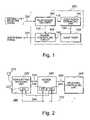
- the wireless LAN device 200includes an antenna 210 , a transmitting/receiving unit 220 which transmits and receives a radio frequency signal, a modem unit 240 which is connected to the transmitting/receiving unit 220 via a connecting line 230 , and a receiving controlling unit 260 which is connected to the modem unit 240 via a connecting line 250 , as shown in FIG. 2 .
- the modem unit 240demodulates a receiving signal to a receiving frame and modulates a transmitting frame to a radio frequency signal.
- the receiving controlling unit 260is operated for achieving low power consumption operation in response to the receiving frame.
- the receiving controlling unit 260outputs a control signal to the transmitting/receiving unit 220 and the modem unit 240 via a connecting line 270 .
- the transmitting/receiving unit 220is an RF circuit for transmitting and receiving a 2.4-GHz band wireless signal.
- the transmitting/receiving unit 220includes an automatic gain control circuit 222 which amplifies the received signal in response to a level of the received signal.
- the automatic gain control circuit 222suspends the amplifying operation in response to the control signal from the receiving controlling unit 260 . While the amplifying operation is suspended, the power consumption in the wireless LAN device 200 is reduced.
- a gain control signalis supplied from a digital analog converter 242 in the modem unit 240 to the automatic gain control circuit 222 via a connecting line 244 .
- the modem unit 240includes an analog digital converter 246 which converts an analog received signal to a digital signal. Also, the modem unit 240 has a function for modulating the converted digital signal to a PLCP(Physical Layer Convergence Procedure) frame and a MAC(Media Access Control) frame. The modem unit 240 measures the level of the receiving signal and supplies the gain control signal to the automatic gain control circuit 222 for controlling receiver sensitivity.
- PLCPPhysical Layer Convergence Procedure
- MACMedia Access Control
- the beginning portion of the PLCP frameincludes a PLCP preamble and a PLCP header.
- the PLCP preambleincludes a synchronization signal field SYNC and a starting field SFD.
- the SYNC fieldis used for deciding whether the communication type is the IEEE 802.11b or the IEEE 802.11g.
- the PLCP headerincludes a SIGNAL field, a SERVICE field, a LENGTH field, and a CRC field.
- the SIGNAL fieldshows a transferring speed of the MAC frame.
- the SERVICE fieldis used for setting a modulation type.
- the LENGTH fieldshows a period of time for transmitting data.
- the CRC fieldis used for checking redundancy.
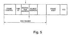
- the MAC frameis appended to the PLCP header.
- the MAC frameincludes a MAC header, a frame body, and an FCS frame.
- the MAC headerincludes a FRAME CONTROL field, a TIME/ID field, a DESTINATION ADDRESS field, and a SOURCE ADDRESS field.
- the frame body and the FCS fieldare appended to the MAC header.
- a combination of the PLCP frame and the MAC frameis called PPDU(PLCP Protocol Data Unit).
- the beacon frame 600which is transmitted from the access point 300 is described by referring to FIG. 6 .
- the beacon frame 600includes the MAC header which includes the FRAME CONTROL field, the TIME/ID field, the DESTINATION ADDRESS field, BSSID field, and a SEQUENCE CONTROL field.
- the frame bodyincludes a TIME STAMP field, a BEACON INTERVAL field, a CAPABILITY INFORMATION field, a SSID field, and a SUPPORT RATE field.
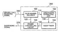
- the receiving controlling unit 260has a PLCP header decoder 100 .
- the PLCP header decoderhas input thereto a receiving signal of the IEEE 802.11b or the IEEE 802.11g, and extracts the PLCP preamble and the PLCP header from the receiving signal.
- the PLCP header decoder 100checks data validity by using the CRC field. If the data validity is confirmed, the extracted PLCP data 110 is output to a length data extracting circuit 102 . If the data validity is not confirmed, the receiving operation is continued.
- the PLCP header decoder 100judges the communication type based on the synchronizing signal in the PLCP preamble. If the communication type is different, the PLCP header decoder 100 outputs a judgment information 120 to a power controlling circuit 106 .
- the mobile station which is used exclusively for the IEEE 802.11greceives the signal of the IEEE 802.11b
- the mobile stationsets data which is included in the LENGTH field to a sleep timer 104 , and the receiving circuit is suspended during when the set time is counted.
- the mobile station which is used exclusively for the IEEE 802.11breceives the signal of the IEEE 802.11g
- the mobile stationsets data which is included in the LENGTH field to a sleep timer 104 , and the receiving circuit is suspended during the set time is counted.
- the length data extracting circuit 102extracts the length data which shows a length of time of data transmitting from the PLCP frame and sets the extracted data 130 to the sleep timer 104 .
- the time of data transmittingis set in 1 ⁇ s units.
- the sleep timer 104is operated by a clock of 1 ⁇ s units. For example, when the length data 130 which has 100 values is set in the sleep timer 104 , the sleep timer 104 outputs a receiving enable signal 140 having a low level while decrementing the set length data in response to the 1 ⁇ s cycle clock, as shown in FIG. 7 . When the counted value becomes 0 value, the receiving enable signal 140 turns to a high level, as shown in FIG. 8 . The sleep timer 104 outputs the receiving enable signal 140 to a power controlling circuit 106 .
- the power controlling circuit 106generates a suspending signal 270 in response to the judgment information 120 and the receiving enable signal 140 as shown in FIG. 1 .
- the suspending signal 270is supplied to the automatic gain controlling circuit 222 and the digital analog converter 242 as shown in FIG. 2 . Therefore, during when the suspending signal 270 is output, the receiving circuit is operated in the power saving mode as shown in FIG. 9 .
- the power saving modeis performed by suspending the clock to the automatic gain controlling circuit 222 and the digital analog circuit 242 .
- a receiving controlling operation of the wireless LAN device 200is described by referring to FIG. 10 .
- a beacon signal 1000is transmitted from the access point at “t 1 ”.
- the communication to the wireless LAN device STA( 1 ) by the IEEE 802.11b or the IEEE 802.11gis started at “t 2 ”.
- the wireless LAN device STA( 2 )receives a transmitting frame 1010 for the wireless LAN device STA( 1 )
- the PLCP header decoder 100 in the wireless LAN device STA( 2 )extracts the PLCP header from the receiving frame.
- the length datais extracted by the length data extracting circuit 102 .
- the validity of the PLCP headeris confirmed by using the CRC.
- the value of the extracted length datais set to the sleep timer 104 in the wireless LAN device STA( 2 ). Then, the low level of the receiving enable signal 140 is output to the power controlling circuit 106 at “t 3 ”. If the PLCP header is invalid, the receiving operation is continued.
- the power controlling circuit 106outputs the suspending signal 270 to the transmitting/receiving unit 220 and the modem unit 240 during the time when the length data is decreased in the sleep timer 104 .
- the transmitting/receiving unit 220 and the modem unit 240enter a suspend mode in response to the suspending signal 270 .
- the receiving circuitstarts working in response to the 0 value of the sleep timer at “t 4 ”. Accordingly, the receiving operation is suspended in a period from “t 3 ” to “t 4 ”, and the power consumption is reduced in this period.
- the wireless LAN device STA( 2 )transmits a transmitting frame 1020 to the access point AP during a period from “t 5 ” to “t 6 ”. In this period, the suspending signal 270 is output to the receiving circuit, and the receiving circuit is suspended. Then, the wireless LAN device STA( 2 ) starts the receiving operation at “t 6 ”.
- the wireless LAN device STA( 2 )receives the PLCP header in the transmitting frame 1030 which is sent from the wireless LAN device STA( 1 ) to the access point AP, the receiving operation in the wireless LAN device STA( 2 ) is suspended at “t 7 ”. Also, the same operation is performed from “t 8 ” to “t 10 ”.
- the judgment that whether the receiving operation can be suspended or notis decided based on the preamble of the PLCP frame. Further, the suspending time is decided by the header of the PLCP frame. As a result, when the wireless LAN device receives the different type of the receiving frame, the wireless LAN device can be suspended during the time which is set by the length data of the PLCP header. Therefore, the low power consumption operation is achieved.
- a receiving controlling unit 700includes a destination address extracting circuit 710 .
- the destination address extracting circuit 710has input thereto the receiving signal 250 and outputs an output signal to the power controlling circuit 720 .
- the destination address extracting circuit 710judges whether the receiving frame is sent for the wireless LAN device or not based on data of a DESTINATION ADDRESS field. If the receiving frame is exclusively available for another wireless LAN device, the suspending signal 270 is output from the power controlling circuit 720 based on a detecting signal 712 and the receiving enable signal 140 . The suspending time is defined by the LENGTH field in the PLCP header. The transmitting/receiving unit 220 and the receiving circuit in the modem unit 240 are suspended by the suspending signal 270 . Also, if the receiving frame is a different communication type, the suspending signal 270 is generated and the receiving circuit is suspended.
- the power or the clock signal for the transmitting/receiving unit 220 and the receiving circuit in the modem unit 240is suspended as shown in FIG. 14 .
- the suspending signal 270is generated based on the extracted destination address, a timing for starting the low power consumption operation can be accelerated.
- a judgment tableis shown in FIG. 13 . If the extracted destination address data which corresponds to the wireless LAN station is received and is judged true by using the FCS, the destination address is truly sent to the targeted wireless LAN station. If the extracted destination address data which corresponds to the wireless LAN station is received and is judged as being in error by using the FCS, the destination address has no relationship to the targeted wireless LAN station. If the extracted destination address data does not correspond to the targeted wireless LAN station, the real destination address has no relationship to the targeted wireless LAN station. That is, if the receiving operation is suspended by using the extracted destination address data without using the FCS, the receiving frame for the targeted wireless LAN station can be received correctly.
- the judgment operation in the receiving controlling unit 700is described by referring to FIG. 15 .
- the PLCP header decoder 100judges whether the type of the receiving frame signal is available for the wireless LAN device or not at step S 1500 . If the communication type is the same as the communication type which is used in the wireless LAN device, a step S 1510 is applied as the next step. If the communication type is different from the communication type which is used in the wireless LAN device, a step S 1520 is applied as the next step.
- the transmitting time length in the LENGTH fieldis received in the step S 1520 .
- the validity of the PLCP headeris verified by using the CRC field.
- the LENGTH data 130is set in the sleep timer 104 after the validity is verified.
- the low level of the receiving enable signal 140is output from the sleep timer 104 to the power controlling circuit 720 , and countdown is started. If the validity of the PLCP header is not verified, the receiving operation is continued.
- the power controlling circuit 720generates the suspending signal 270 in response to the receiving enable signal 140 and the result of the judgment in the PLCP header decoder 100 , and outputs the suspending signal 270 to the transmitting/receiving unit 220 and the modem unit 240 .
- the suspending signal 270is output from the power controlling circuit 720 , operating of the automatic gain controlling circuit 222 and the digital analog converter 242 are suspended.
- the suspending operationcan be performed by suspending the clock signal which is input to the automatic gain controlling circuit 222 and the digital analog converter 242 .
- a step 1510is applied as the next step.
- the destination addressis extracted by the destination address extracting circuit 710 , and it is judged whether the receiving frame is valid for the station or not. If the receiving frame is not valid for the station, the step S 1520 is applied and the LENGTH data 130 is set in the sleep timer 104 .
- the sleep timer 104outputs the low level of the receiving enable signal 140 to the power controlling circuit 720 in response to setting the LENGTH data 130 . Then the suspending operation is performed in the step S 1530 .
- the power controlling circuit 720stops outputting the suspending signal 270 , and the receiving operation is restarted.
- the receiving operationis continued as a step S 1540 .
- the suspending operationcan be performed.
Landscapes
- Engineering & Computer Science (AREA)
- Computer Networks & Wireless Communication (AREA)
- Signal Processing (AREA)
- Mobile Radio Communication Systems (AREA)
- Small-Scale Networks (AREA)
Abstract
Description
Claims (4)
Applications Claiming Priority (2)
| Application Number | Priority Date | Filing Date | Title |
|---|---|---|---|
| JP2004115312AJP4288368B2 (en) | 2004-04-09 | 2004-04-09 | Reception control method and wireless LAN apparatus |
| JP115312/2004 | 2004-04-09 |
Publications (2)
| Publication Number | Publication Date |
|---|---|
| US20050226204A1 US20050226204A1 (en) | 2005-10-13 |
| US7382764B2true US7382764B2 (en) | 2008-06-03 |
Family
ID=35060449
Family Applications (1)
| Application Number | Title | Priority Date | Filing Date |
|---|---|---|---|
| US11/055,590Expired - Fee RelatedUS7382764B2 (en) | 2004-04-09 | 2005-02-11 | Method of controlling a receiving operation |
Country Status (2)
| Country | Link |
|---|---|
| US (1) | US7382764B2 (en) |
| JP (1) | JP4288368B2 (en) |
Cited By (40)
| Publication number | Priority date | Publication date | Assignee | Title |
|---|---|---|---|---|
| US20060189288A1 (en)* | 2005-02-24 | 2006-08-24 | Xin Jin | Methods and apparatus for controlling a gain state of a wireless receiver operating in an idle mode |
| US20070097908A1 (en)* | 2005-10-27 | 2007-05-03 | Qualcomm Incorporated | Scalable frequency band operation in wireless communication systems |
| US20080031218A1 (en)* | 2006-06-29 | 2008-02-07 | Fujitsu Limited | Wireless telecommunication apparatus and wireless telecommunication method |
| US20090208263A1 (en)* | 2008-02-19 | 2009-08-20 | Konica Minolta Business Technologies, Inc. | Fixing device and image forming apparatus |
| US20100085905A1 (en)* | 2008-10-03 | 2010-04-08 | Kiyotaka Matsue | Communication system and wireless communication device |
| US8098569B2 (en) | 2000-09-13 | 2012-01-17 | Qualcomm Incorporated | Signaling method in an OFDM multiple access system |
| US8446892B2 (en) | 2005-03-16 | 2013-05-21 | Qualcomm Incorporated | Channel structures for a quasi-orthogonal multiple-access communication system |
| US8462859B2 (en) | 2005-06-01 | 2013-06-11 | Qualcomm Incorporated | Sphere decoding apparatus |
| US8477684B2 (en) | 2005-10-27 | 2013-07-02 | Qualcomm Incorporated | Acknowledgement of control messages in a wireless communication system |
| US8565194B2 (en) | 2005-10-27 | 2013-10-22 | Qualcomm Incorporated | Puncturing signaling channel for a wireless communication system |
| US8582509B2 (en) | 2005-10-27 | 2013-11-12 | Qualcomm Incorporated | Scalable frequency band operation in wireless communication systems |
| US8582548B2 (en) | 2005-11-18 | 2013-11-12 | Qualcomm Incorporated | Frequency division multiple access schemes for wireless communication |
| US8599945B2 (en) | 2005-06-16 | 2013-12-03 | Qualcomm Incorporated | Robust rank prediction for a MIMO system |
| US8611284B2 (en) | 2005-05-31 | 2013-12-17 | Qualcomm Incorporated | Use of supplemental assignments to decrement resources |
| US8644292B2 (en) | 2005-08-24 | 2014-02-04 | Qualcomm Incorporated | Varied transmission time intervals for wireless communication system |
| US8693405B2 (en) | 2005-10-27 | 2014-04-08 | Qualcomm Incorporated | SDMA resource management |
| US8879511B2 (en) | 2005-10-27 | 2014-11-04 | Qualcomm Incorporated | Assignment acknowledgement for a wireless communication system |
| US8885628B2 (en) | 2005-08-08 | 2014-11-11 | Qualcomm Incorporated | Code division multiplexing in a single-carrier frequency division multiple access system |
| US8917654B2 (en) | 2005-04-19 | 2014-12-23 | Qualcomm Incorporated | Frequency hopping design for single carrier FDMA systems |
| US9088384B2 (en) | 2005-10-27 | 2015-07-21 | Qualcomm Incorporated | Pilot symbol transmission in wireless communication systems |
| US9130810B2 (en) | 2000-09-13 | 2015-09-08 | Qualcomm Incorporated | OFDM communications methods and apparatus |
| US9137822B2 (en) | 2004-07-21 | 2015-09-15 | Qualcomm Incorporated | Efficient signaling over access channel |
| US9136974B2 (en) | 2005-08-30 | 2015-09-15 | Qualcomm Incorporated | Precoding and SDMA support |
| US9143305B2 (en) | 2005-03-17 | 2015-09-22 | Qualcomm Incorporated | Pilot signal transmission for an orthogonal frequency division wireless communication system |
| US9144060B2 (en) | 2005-10-27 | 2015-09-22 | Qualcomm Incorporated | Resource allocation for shared signaling channels |
| US9148256B2 (en) | 2004-07-21 | 2015-09-29 | Qualcomm Incorporated | Performance based rank prediction for MIMO design |
| US9154211B2 (en) | 2005-03-11 | 2015-10-06 | Qualcomm Incorporated | Systems and methods for beamforming feedback in multi antenna communication systems |
| US9172453B2 (en) | 2005-10-27 | 2015-10-27 | Qualcomm Incorporated | Method and apparatus for pre-coding frequency division duplexing system |
| US9179319B2 (en) | 2005-06-16 | 2015-11-03 | Qualcomm Incorporated | Adaptive sectorization in cellular systems |
| US9184870B2 (en) | 2005-04-01 | 2015-11-10 | Qualcomm Incorporated | Systems and methods for control channel signaling |
| US9210651B2 (en) | 2005-10-27 | 2015-12-08 | Qualcomm Incorporated | Method and apparatus for bootstraping information in a communication system |
| US9209956B2 (en) | 2005-08-22 | 2015-12-08 | Qualcomm Incorporated | Segment sensitive scheduling |
| US9225488B2 (en) | 2005-10-27 | 2015-12-29 | Qualcomm Incorporated | Shared signaling channel |
| US9225416B2 (en) | 2005-10-27 | 2015-12-29 | Qualcomm Incorporated | Varied signaling channels for a reverse link in a wireless communication system |
| US9246560B2 (en) | 2005-03-10 | 2016-01-26 | Qualcomm Incorporated | Systems and methods for beamforming and rate control in a multi-input multi-output communication systems |
| US9307544B2 (en) | 2005-04-19 | 2016-04-05 | Qualcomm Incorporated | Channel quality reporting for adaptive sectorization |
| US9461859B2 (en) | 2005-03-17 | 2016-10-04 | Qualcomm Incorporated | Pilot signal transmission for an orthogonal frequency division wireless communication system |
| US9520972B2 (en) | 2005-03-17 | 2016-12-13 | Qualcomm Incorporated | Pilot signal transmission for an orthogonal frequency division wireless communication system |
| US9660776B2 (en) | 2005-08-22 | 2017-05-23 | Qualcomm Incorporated | Method and apparatus for providing antenna diversity in a wireless communication system |
| US9693307B2 (en) | 2014-06-30 | 2017-06-27 | Apple Inc. | Early termination of reception of wireless transmissions |
Families Citing this family (28)
| Publication number | Priority date | Publication date | Assignee | Title |
|---|---|---|---|---|
| US8005032B2 (en)* | 2005-01-21 | 2011-08-23 | Research In Motion Limited | Maintaining delivery traffic indication message (DTIM) periods on a per-wireless client device basis |
| US7593417B2 (en) | 2005-01-21 | 2009-09-22 | Research In Motion Limited | Handling broadcast and multicast traffic as unicast traffic in a wireless network |
| KR100703794B1 (en)* | 2005-09-02 | 2007-04-06 | 삼성전자주식회사 | Method and device for reducing power consumption of wireless LAN devices |
| US20070070934A1 (en)* | 2005-09-28 | 2007-03-29 | Pieter Van Rooyen | Method and system for a reconfigurable OFDM radio supporting diversity |
| US20070070179A1 (en)* | 2005-09-28 | 2007-03-29 | Pieter Van Rooyen | Method and system for a reconfigurable OFDM radio |
| JP4816123B2 (en)* | 2006-02-17 | 2011-11-16 | ソニー株式会社 | Wireless communication apparatus and wireless communication method |
| JP4762007B2 (en)* | 2006-03-03 | 2011-08-31 | パナソニック株式会社 | Relay device, communication terminal, and communication system |
| JP4895179B2 (en)* | 2006-06-22 | 2012-03-14 | キヤノン株式会社 | IMAGING DEVICE, IMAGING DEVICE CONTROLLER, IMAGING DEVICE CONTROL METHOD, PROGRAM, AND STORAGE MEDIUM |
| JP2008091988A (en)* | 2006-09-29 | 2008-04-17 | Nec Electronics Corp | Reception control method and receiving apparatus |
| US8238278B2 (en)* | 2007-01-08 | 2012-08-07 | Hellosoft, Inc. | Hardware-based beacon processing |
| JP5075526B2 (en) | 2007-08-10 | 2012-11-21 | 株式会社東芝 | Wireless communication device and control program for wireless communication device |
| WO2009062186A2 (en)* | 2007-11-09 | 2009-05-14 | G2 Microsystems Pty. Ltd | Early receiver shutdown |
| JP2009225334A (en) | 2008-03-18 | 2009-10-01 | Toshiba Corp | Radio communication equipment |
| JP5073587B2 (en)* | 2008-06-04 | 2012-11-14 | 日立情報通信エンジニアリング株式会社 | Wireless multi-hop communication device and communication control method thereof |
| JP5231925B2 (en)* | 2008-10-06 | 2013-07-10 | 株式会社エヌ・ティ・ティ・ドコモ | Wireless communication terminal, wireless base station, and communication method |
| JP2010199955A (en)* | 2009-02-25 | 2010-09-09 | Seiko Instruments Inc | Information processing apparatus, wireless terminal, information processing program, and wireless terminal program |
| US8817698B2 (en)* | 2009-10-18 | 2014-08-26 | Intel Corporation | Device, system and method of selectively aborting reception of wireless communication packets |
| KR101696206B1 (en)* | 2009-11-13 | 2017-01-13 | 오렌지 | Method for deactivating at least one component of an entity of a communication network, and corresponding computer program and device |
| DE112010006113B4 (en)* | 2009-12-18 | 2016-09-29 | Electronics And Telecommunications Research Institute | A method and receiver for receiving data in a wireless packet communication system in which there are simultaneous communications with different terminals |
| CN103378929B (en) | 2012-04-23 | 2018-07-24 | 中兴通讯股份有限公司 | The method of reseptance and device of radio frames |
| CN103476130B (en)* | 2012-06-08 | 2018-09-11 | 中兴通讯股份有限公司 | A kind of contention access method and site apparatus |
| US9521696B2 (en)* | 2012-07-31 | 2016-12-13 | Hewlett Packard Enterprise Development Lp | Wireless access point cell ID insertion in frame header |
| US8964615B2 (en)* | 2012-09-06 | 2015-02-24 | Qualcomm Incorporated | Methods and devices for facilitating early header decoding in communications devices |
| JP6760063B2 (en) | 2014-07-11 | 2020-09-23 | ソニー株式会社 | Information processing equipment, communication system and information processing method |
| TWI576823B (en)* | 2015-05-12 | 2017-04-01 | A sound transmission system for improving audio recognition rate and its data processing | |
| TWI569592B (en)* | 2015-05-12 | 2017-02-01 | Information transmission system for improving the correctness of data and its data processing | |
| JP2018061140A (en)* | 2016-10-05 | 2018-04-12 | 株式会社東芝 | Radio communication device and radio communication method |
| US11005585B1 (en) | 2019-12-31 | 2021-05-11 | Juniper Networks, Inc. | Transporting client timing information across a network |
Citations (12)
| Publication number | Priority date | Publication date | Assignee | Title |
|---|---|---|---|---|
| JPH08195754A (en) | 1995-01-18 | 1996-07-30 | Fujitsu Ltd | Standby method for mobile station in wireless LAN |
| US6256509B1 (en)* | 1998-03-19 | 2001-07-03 | Hitachi, Ltd. | Broadcast information delivering system |
| US20020090959A1 (en)* | 2001-01-08 | 2002-07-11 | Rajiv Laroia | Apparatus and method for use in paging mode in wireless communications systems |
| US20020098840A1 (en)* | 1998-10-09 | 2002-07-25 | Hanson Aaron D. | Method and apparatus for providing mobile and other intermittent connectivity in a computing environment |
| JP2003299141A (en) | 2002-04-05 | 2003-10-17 | Canon Inc | Wireless communication device |
| US20040059825A1 (en)* | 2002-02-08 | 2004-03-25 | Edwards Paul C. | Medium access control in a wireless network |
| US20040179536A1 (en)* | 2003-03-10 | 2004-09-16 | Pascal Thubert | Arrangement for traversing an IPv4 network by IPv6 mobile nodes |
| US6876631B2 (en)* | 2000-01-25 | 2005-04-05 | Ntt Docomo, Inc. | Method and apparatus for frame transmission |
| US6909702B2 (en)* | 2001-03-28 | 2005-06-21 | Qualcomm, Incorporated | Method and apparatus for out-of-band transmission of broadcast service option in a wireless communication system |
| US6985459B2 (en)* | 2002-08-21 | 2006-01-10 | Qualcomm Incorporated | Early transmission and playout of packets in wireless communication systems |
| US20060072614A1 (en)* | 2003-03-26 | 2006-04-06 | Sony Corporation | Radio communication system |
| US7031666B2 (en)* | 2001-03-28 | 2006-04-18 | Qualcomm Incorporated. | Method and apparatus for header compression in a wireless communication system |
- 2004
- 2004-04-09JPJP2004115312Apatent/JP4288368B2/ennot_activeExpired - Fee Related
- 2005
- 2005-02-11USUS11/055,590patent/US7382764B2/ennot_activeExpired - Fee Related
Patent Citations (12)
| Publication number | Priority date | Publication date | Assignee | Title |
|---|---|---|---|---|
| JPH08195754A (en) | 1995-01-18 | 1996-07-30 | Fujitsu Ltd | Standby method for mobile station in wireless LAN |
| US6256509B1 (en)* | 1998-03-19 | 2001-07-03 | Hitachi, Ltd. | Broadcast information delivering system |
| US20020098840A1 (en)* | 1998-10-09 | 2002-07-25 | Hanson Aaron D. | Method and apparatus for providing mobile and other intermittent connectivity in a computing environment |
| US6876631B2 (en)* | 2000-01-25 | 2005-04-05 | Ntt Docomo, Inc. | Method and apparatus for frame transmission |
| US20020090959A1 (en)* | 2001-01-08 | 2002-07-11 | Rajiv Laroia | Apparatus and method for use in paging mode in wireless communications systems |
| US6909702B2 (en)* | 2001-03-28 | 2005-06-21 | Qualcomm, Incorporated | Method and apparatus for out-of-band transmission of broadcast service option in a wireless communication system |
| US7031666B2 (en)* | 2001-03-28 | 2006-04-18 | Qualcomm Incorporated. | Method and apparatus for header compression in a wireless communication system |
| US20040059825A1 (en)* | 2002-02-08 | 2004-03-25 | Edwards Paul C. | Medium access control in a wireless network |
| JP2003299141A (en) | 2002-04-05 | 2003-10-17 | Canon Inc | Wireless communication device |
| US6985459B2 (en)* | 2002-08-21 | 2006-01-10 | Qualcomm Incorporated | Early transmission and playout of packets in wireless communication systems |
| US20040179536A1 (en)* | 2003-03-10 | 2004-09-16 | Pascal Thubert | Arrangement for traversing an IPv4 network by IPv6 mobile nodes |
| US20060072614A1 (en)* | 2003-03-26 | 2006-04-06 | Sony Corporation | Radio communication system |
Cited By (67)
| Publication number | Priority date | Publication date | Assignee | Title |
|---|---|---|---|---|
| US9426012B2 (en) | 2000-09-13 | 2016-08-23 | Qualcomm Incorporated | Signaling method in an OFDM multiple access system |
| US8098568B2 (en) | 2000-09-13 | 2012-01-17 | Qualcomm Incorporated | Signaling method in an OFDM multiple access system |
| US11032035B2 (en) | 2000-09-13 | 2021-06-08 | Qualcomm Incorporated | Signaling method in an OFDM multiple access system |
| US8098569B2 (en) | 2000-09-13 | 2012-01-17 | Qualcomm Incorporated | Signaling method in an OFDM multiple access system |
| US10313069B2 (en) | 2000-09-13 | 2019-06-04 | Qualcomm Incorporated | Signaling method in an OFDM multiple access system |
| US9130810B2 (en) | 2000-09-13 | 2015-09-08 | Qualcomm Incorporated | OFDM communications methods and apparatus |
| US9137822B2 (en) | 2004-07-21 | 2015-09-15 | Qualcomm Incorporated | Efficient signaling over access channel |
| US10517114B2 (en) | 2004-07-21 | 2019-12-24 | Qualcomm Incorporated | Efficient signaling over access channel |
| US10849156B2 (en) | 2004-07-21 | 2020-11-24 | Qualcomm Incorporated | Efficient signaling over access channel |
| US9148256B2 (en) | 2004-07-21 | 2015-09-29 | Qualcomm Incorporated | Performance based rank prediction for MIMO design |
| US10237892B2 (en) | 2004-07-21 | 2019-03-19 | Qualcomm Incorporated | Efficient signaling over access channel |
| US11039468B2 (en) | 2004-07-21 | 2021-06-15 | Qualcomm Incorporated | Efficient signaling over access channel |
| US10194463B2 (en) | 2004-07-21 | 2019-01-29 | Qualcomm Incorporated | Efficient signaling over access channel |
| US20110053542A1 (en)* | 2005-02-24 | 2011-03-03 | Research In Motion Limited | Methods And Apparatus For Controlling A Gain State Of A Wireless Receiver Operating In An Mode |
| US20090068972A1 (en)* | 2005-02-24 | 2009-03-12 | Research In Motion Limited | Methods And Apparatus For Controlling A Gain State Of A Wireless Receiver Operating In An Idle Mode |
| US20060189288A1 (en)* | 2005-02-24 | 2006-08-24 | Xin Jin | Methods and apparatus for controlling a gain state of a wireless receiver operating in an idle mode |
| US8275335B2 (en) | 2005-02-24 | 2012-09-25 | Research In Motion Limited | Methods and apparatus for controlling a gain state of a wireless receiver operating in an idle mode |
| US8116712B2 (en) | 2005-02-24 | 2012-02-14 | Research In Motion Limited | Methods and apparatus for controlling a gain state of a wireless receiver operating in an idle mode |
| US7853230B2 (en) | 2005-02-24 | 2010-12-14 | Research In Motion Limited | Methods and apparatus for controlling a gain state of a wireless receiver operating in an idle mode |
| US7463872B2 (en)* | 2005-02-24 | 2008-12-09 | Research In Motion Limited | Methods and apparatus for controlling a gain state of a wireless receiver operating in an idle mode |
| US9246560B2 (en) | 2005-03-10 | 2016-01-26 | Qualcomm Incorporated | Systems and methods for beamforming and rate control in a multi-input multi-output communication systems |
| US9154211B2 (en) | 2005-03-11 | 2015-10-06 | Qualcomm Incorporated | Systems and methods for beamforming feedback in multi antenna communication systems |
| US8547951B2 (en) | 2005-03-16 | 2013-10-01 | Qualcomm Incorporated | Channel structures for a quasi-orthogonal multiple-access communication system |
| US8446892B2 (en) | 2005-03-16 | 2013-05-21 | Qualcomm Incorporated | Channel structures for a quasi-orthogonal multiple-access communication system |
| US9461859B2 (en) | 2005-03-17 | 2016-10-04 | Qualcomm Incorporated | Pilot signal transmission for an orthogonal frequency division wireless communication system |
| US9143305B2 (en) | 2005-03-17 | 2015-09-22 | Qualcomm Incorporated | Pilot signal transmission for an orthogonal frequency division wireless communication system |
| US9520972B2 (en) | 2005-03-17 | 2016-12-13 | Qualcomm Incorporated | Pilot signal transmission for an orthogonal frequency division wireless communication system |
| US9184870B2 (en) | 2005-04-01 | 2015-11-10 | Qualcomm Incorporated | Systems and methods for control channel signaling |
| US9307544B2 (en) | 2005-04-19 | 2016-04-05 | Qualcomm Incorporated | Channel quality reporting for adaptive sectorization |
| US9408220B2 (en) | 2005-04-19 | 2016-08-02 | Qualcomm Incorporated | Channel quality reporting for adaptive sectorization |
| US8917654B2 (en) | 2005-04-19 | 2014-12-23 | Qualcomm Incorporated | Frequency hopping design for single carrier FDMA systems |
| US9036538B2 (en) | 2005-04-19 | 2015-05-19 | Qualcomm Incorporated | Frequency hopping design for single carrier FDMA systems |
| US8611284B2 (en) | 2005-05-31 | 2013-12-17 | Qualcomm Incorporated | Use of supplemental assignments to decrement resources |
| US8462859B2 (en) | 2005-06-01 | 2013-06-11 | Qualcomm Incorporated | Sphere decoding apparatus |
| US8599945B2 (en) | 2005-06-16 | 2013-12-03 | Qualcomm Incorporated | Robust rank prediction for a MIMO system |
| US9179319B2 (en) | 2005-06-16 | 2015-11-03 | Qualcomm Incorporated | Adaptive sectorization in cellular systems |
| US8885628B2 (en) | 2005-08-08 | 2014-11-11 | Qualcomm Incorporated | Code division multiplexing in a single-carrier frequency division multiple access system |
| US9693339B2 (en) | 2005-08-08 | 2017-06-27 | Qualcomm Incorporated | Code division multiplexing in a single-carrier frequency division multiple access system |
| US9209956B2 (en) | 2005-08-22 | 2015-12-08 | Qualcomm Incorporated | Segment sensitive scheduling |
| US9860033B2 (en) | 2005-08-22 | 2018-01-02 | Qualcomm Incorporated | Method and apparatus for antenna diversity in multi-input multi-output communication systems |
| US9660776B2 (en) | 2005-08-22 | 2017-05-23 | Qualcomm Incorporated | Method and apparatus for providing antenna diversity in a wireless communication system |
| US9246659B2 (en) | 2005-08-22 | 2016-01-26 | Qualcomm Incorporated | Segment sensitive scheduling |
| US9240877B2 (en) | 2005-08-22 | 2016-01-19 | Qualcomm Incorporated | Segment sensitive scheduling |
| US8787347B2 (en) | 2005-08-24 | 2014-07-22 | Qualcomm Incorporated | Varied transmission time intervals for wireless communication system |
| US8644292B2 (en) | 2005-08-24 | 2014-02-04 | Qualcomm Incorporated | Varied transmission time intervals for wireless communication system |
| US9136974B2 (en) | 2005-08-30 | 2015-09-15 | Qualcomm Incorporated | Precoding and SDMA support |
| US8582509B2 (en) | 2005-10-27 | 2013-11-12 | Qualcomm Incorporated | Scalable frequency band operation in wireless communication systems |
| US8879511B2 (en) | 2005-10-27 | 2014-11-04 | Qualcomm Incorporated | Assignment acknowledgement for a wireless communication system |
| US9172453B2 (en) | 2005-10-27 | 2015-10-27 | Qualcomm Incorporated | Method and apparatus for pre-coding frequency division duplexing system |
| US8693405B2 (en) | 2005-10-27 | 2014-04-08 | Qualcomm Incorporated | SDMA resource management |
| US10805038B2 (en) | 2005-10-27 | 2020-10-13 | Qualcomm Incorporated | Puncturing signaling channel for a wireless communication system |
| US9225416B2 (en) | 2005-10-27 | 2015-12-29 | Qualcomm Incorporated | Varied signaling channels for a reverse link in a wireless communication system |
| US8842619B2 (en) | 2005-10-27 | 2014-09-23 | Qualcomm Incorporated | Scalable frequency band operation in wireless communication systems |
| US9088384B2 (en) | 2005-10-27 | 2015-07-21 | Qualcomm Incorporated | Pilot symbol transmission in wireless communication systems |
| US9210651B2 (en) | 2005-10-27 | 2015-12-08 | Qualcomm Incorporated | Method and apparatus for bootstraping information in a communication system |
| US8045512B2 (en) | 2005-10-27 | 2011-10-25 | Qualcomm Incorporated | Scalable frequency band operation in wireless communication systems |
| US9144060B2 (en) | 2005-10-27 | 2015-09-22 | Qualcomm Incorporated | Resource allocation for shared signaling channels |
| US20070097908A1 (en)* | 2005-10-27 | 2007-05-03 | Qualcomm Incorporated | Scalable frequency band operation in wireless communication systems |
| US9225488B2 (en) | 2005-10-27 | 2015-12-29 | Qualcomm Incorporated | Shared signaling channel |
| US8565194B2 (en) | 2005-10-27 | 2013-10-22 | Qualcomm Incorporated | Puncturing signaling channel for a wireless communication system |
| US8477684B2 (en) | 2005-10-27 | 2013-07-02 | Qualcomm Incorporated | Acknowledgement of control messages in a wireless communication system |
| US8582548B2 (en) | 2005-11-18 | 2013-11-12 | Qualcomm Incorporated | Frequency division multiple access schemes for wireless communication |
| US8681764B2 (en) | 2005-11-18 | 2014-03-25 | Qualcomm Incorporated | Frequency division multiple access schemes for wireless communication |
| US20080031218A1 (en)* | 2006-06-29 | 2008-02-07 | Fujitsu Limited | Wireless telecommunication apparatus and wireless telecommunication method |
| US20090208263A1 (en)* | 2008-02-19 | 2009-08-20 | Konica Minolta Business Technologies, Inc. | Fixing device and image forming apparatus |
| US20100085905A1 (en)* | 2008-10-03 | 2010-04-08 | Kiyotaka Matsue | Communication system and wireless communication device |
| US9693307B2 (en) | 2014-06-30 | 2017-06-27 | Apple Inc. | Early termination of reception of wireless transmissions |
Also Published As
| Publication number | Publication date |
|---|---|
| JP2005303585A (en) | 2005-10-27 |
| US20050226204A1 (en) | 2005-10-13 |
| JP4288368B2 (en) | 2009-07-01 |
Similar Documents
| Publication | Publication Date | Title |
|---|---|---|
| US7382764B2 (en) | Method of controlling a receiving operation | |
| US12232034B2 (en) | Wireless communication method using wake-up radio and wireless communication terminal using same | |
| US11395229B2 (en) | Method for receiving frame in wireless LAN system, and wireless terminal using same | |
| US8064411B2 (en) | Speculative power save | |
| US8427990B2 (en) | Wireless communication system, wireless communication apparatus, wireless communication method, and program | |
| US20190253972A1 (en) | Method for managing power in wireless lan system and wireless terminal using same | |
| KR101838419B1 (en) | Method and apparatus for operating based on power save mode in wireless lan | |
| US20060030362A1 (en) | Radio communication system | |
| JP2017060188A (en) | Power saving method in wireless communication system | |
| WO2016021792A1 (en) | Power save mode-based operating method and apparatus in wireless lan | |
| JP2010093489A (en) | Wireless communication device and wireless communication method | |
| US11425643B2 (en) | Method for performing communication in wireless LAN system, and wireless terminal using same | |
| CN110574442A (en) | Low power wake-up in wireless networks | |
| US11160024B2 (en) | Method for receiving frame in wireless LAN system, and wireless terminal using same | |
| US11277795B2 (en) | Method for receiving wake up packet via wake up radio module in wireless LAN system and wireless terminal using same | |
| US20190200298A1 (en) | Method and apparatus for transmitting wake-up packet in wireless lan system | |
| KR20050107427A (en) | Maintaining synchronization between a qos access point and qos stations in an ieee 802.11e wlan | |
| US11330523B2 (en) | Method for performing communication on basis of power-saving operation in wireless LAN system, and wireless terminal using same | |
| US11166236B2 (en) | Method for communication in WLAN system and wireless terminal using the same | |
| US11277796B2 (en) | Method for performing communication in wireless LAN system, and wireless terminal using same | |
| US11425651B2 (en) | Method for communication in wireless LAN system and wireless terminal using same | |
| JP2010093441A (en) | Wireless communication terminal, wireless communication base station and method | |
| US20200351773A1 (en) | Method for communicating in wireless lan system and wireless terminal using same | |
| US12363633B2 (en) | Power save protocols for multi-link devices |
Legal Events
| Date | Code | Title | Description |
|---|---|---|---|
| AS | Assignment | Owner name:OKI ELECTRIC INDUSTRY CO., LTD., JAPAN Free format text:ASSIGNMENT OF ASSIGNORS INTEREST;ASSIGNOR:UEHARA, TERUAKI;REEL/FRAME:016279/0204 Effective date:20050120 | |
| FEPP | Fee payment procedure | Free format text:PAYOR NUMBER ASSIGNED (ORIGINAL EVENT CODE: ASPN); ENTITY STATUS OF PATENT OWNER: LARGE ENTITY | |
| AS | Assignment | Owner name:OKI SEMICONDUCTOR CO., LTD., JAPAN Free format text:CHANGE OF NAME;ASSIGNOR:OKI ELECTRIC INDUSTRY CO., LTD.;REEL/FRAME:022052/0797 Effective date:20081001 Owner name:OKI SEMICONDUCTOR CO., LTD.,JAPAN Free format text:CHANGE OF NAME;ASSIGNOR:OKI ELECTRIC INDUSTRY CO., LTD.;REEL/FRAME:022052/0797 Effective date:20081001 | |
| FPAY | Fee payment | Year of fee payment:4 | |
| AS | Assignment | Owner name:LAPIS SEMICONDUCTOR CO., LTD., JAPAN Free format text:CHANGE OF NAME;ASSIGNOR:OKI SEMICONDUCTOR CO., LTD;REEL/FRAME:032495/0483 Effective date:20111003 | |
| REMI | Maintenance fee reminder mailed | ||
| LAPS | Lapse for failure to pay maintenance fees | ||
| STCH | Information on status: patent discontinuation | Free format text:PATENT EXPIRED DUE TO NONPAYMENT OF MAINTENANCE FEES UNDER 37 CFR 1.362 | |
| FP | Lapsed due to failure to pay maintenance fee | Effective date:20160603 |