US7381914B1 - Button actuation assembly - Google Patents
Button actuation assemblyDownload PDFInfo
- Publication number
- US7381914B1 US7381914B1US11/560,381US56038106AUS7381914B1US 7381914 B1US7381914 B1US 7381914B1US 56038106 AUS56038106 AUS 56038106AUS 7381914 B1US7381914 B1US 7381914B1
- Authority
- US
- United States
- Prior art keywords
- button
- switch
- retainer
- housing
- buffer
- Prior art date
- Legal status (The legal status is an assumption and is not a legal conclusion. Google has not performed a legal analysis and makes no representation as to the accuracy of the status listed.)
- Active
Links
- 230000003213activating effectEffects0.000claimsabstractdescription13
- 230000035939shockEffects0.000abstractdescription13
- 239000012528membraneSubstances0.000description14
- 239000000463materialSubstances0.000description10
- 229920001971elastomerPolymers0.000description6
- 239000000806elastomerSubstances0.000description5
- 230000007246mechanismEffects0.000description3
- 239000004033plasticSubstances0.000description3
- 229920003023plasticPolymers0.000description3
- 239000002861polymer materialSubstances0.000description3
- XLYOFNOQVPJJNP-UHFFFAOYSA-NwaterSubstancesOXLYOFNOQVPJJNP-UHFFFAOYSA-N0.000description3
- 229920002943EPDM rubberPolymers0.000description2
- 239000012190activatorSubstances0.000description2
- 230000009286beneficial effectEffects0.000description2
- 150000001875compoundsChemical class0.000description2
- 239000000428dustSubstances0.000description2
- 238000012986modificationMethods0.000description2
- 230000004048modificationEffects0.000description2
- 239000007787solidSubstances0.000description2
- 239000006096absorbing agentSubstances0.000description1
- 238000010521absorption reactionMethods0.000description1
- DHKHKXVYLBGOIT-UHFFFAOYSA-Nacetaldehyde Diethyl AcetalNatural productsCCOC(C)OCCDHKHKXVYLBGOIT-UHFFFAOYSA-N0.000description1
- 125000002777acetyl groupChemical class[H]C([H])([H])C(*)=O0.000description1
- 230000009471actionEffects0.000description1
- 230000004913activationEffects0.000description1
- 239000000853adhesiveSubstances0.000description1
- 230000001070adhesive effectEffects0.000description1
- 230000000712assemblyEffects0.000description1
- 238000000429assemblyMethods0.000description1
- 230000002238attenuated effectEffects0.000description1
- 238000005452bendingMethods0.000description1
- 239000002131composite materialSubstances0.000description1
- 239000000356contaminantSubstances0.000description1
- 230000001066destructive effectEffects0.000description1
- 239000013536elastomeric materialSubstances0.000description1
- 239000007788liquidSubstances0.000description1
- 229910001092metal group alloyInorganic materials0.000description1
- 238000000034methodMethods0.000description1
- 239000000203mixtureSubstances0.000description1
- 239000002991molded plasticSubstances0.000description1
- 229920001084poly(chloroprene)Polymers0.000description1
- 230000001902propagating effectEffects0.000description1
- 239000005060rubberSubstances0.000description1
- 229920006342thermoplastic vulcanizatePolymers0.000description1
Images


Classifications
- H—ELECTRICITY
- H01—ELECTRIC ELEMENTS
- H01H—ELECTRIC SWITCHES; RELAYS; SELECTORS; EMERGENCY PROTECTIVE DEVICES
- H01H3/00—Mechanisms for operating contacts
- H01H3/32—Driving mechanisms, i.e. for transmitting driving force to the contacts
- H01H3/38—Driving mechanisms, i.e. for transmitting driving force to the contacts using spring or other flexible shaft coupling
- H—ELECTRICITY
- H01—ELECTRIC ELEMENTS
- H01H—ELECTRIC SWITCHES; RELAYS; SELECTORS; EMERGENCY PROTECTIVE DEVICES
- H01H3/00—Mechanisms for operating contacts
- H01H3/60—Mechanical arrangements for preventing or damping vibration or shock
- H—ELECTRICITY
- H01—ELECTRIC ELEMENTS
- H01H—ELECTRIC SWITCHES; RELAYS; SELECTORS; EMERGENCY PROTECTIVE DEVICES
- H01H3/00—Mechanisms for operating contacts
- H01H3/32—Driving mechanisms, i.e. for transmitting driving force to the contacts
- H01H3/46—Driving mechanisms, i.e. for transmitting driving force to the contacts using rod or lever linkage, e.g. toggle
- H01H2003/463—Driving mechanisms, i.e. for transmitting driving force to the contacts using rod or lever linkage, e.g. toggle using a blade spring lever for perpendicular force transmission
- H—ELECTRICITY
- H01—ELECTRIC ELEMENTS
- H01H—ELECTRIC SWITCHES; RELAYS; SELECTORS; EMERGENCY PROTECTIVE DEVICES
- H01H2239/00—Miscellaneous
- H01H2239/032—Anti-tamper
- H—ELECTRICITY
- H01—ELECTRIC ELEMENTS
- H01H—ELECTRIC SWITCHES; RELAYS; SELECTORS; EMERGENCY PROTECTIVE DEVICES
- H01H9/00—Details of switching devices, not covered by groups H01H1/00 - H01H7/00
- H01H9/02—Bases, casings, or covers
- H01H9/0214—Hand-held casings
- H01H9/0235—Hand-held casings specially adapted for remote control, e.g. of audio or video apparatus
- H01H9/0242—Protective enclosures; Cushioning means
Definitions
- the present inventionrelates to an improved button actuation assembly for activating a switch.
- buttons actuatorsfor activating one or more functions of the device.
- a button actuatoris provided for activating a switch for the laser beam that scans barcodes.
- These button actuators or actuation assembliesmay come in a variety of mechanical configurations and generally have a button that the user presses to activate the laser scan function.
- the buttonis an integral part of the electrical switch that electrically activates the laser beam scanner, more often, for aesthetical reasons, the button may be a separate structure that is directly or indirectly linked to the switch inside the hand held device. Often, the button is shaped to aesthetically blend in with the shape and appearance of the hand held device.
- the buttonis merely a mechanical linkage that transfers the force exerted on the button directly to the switch inside the hand held device.
- hand held point-of-sale barcode readersgenerally are subject to impact shocks from being dropped or intentionally being banged against a hard surface by the users.
- hand held barcode readersare used at locations such as point-of-sale cash registers, warehouses and hospital floors. Hence, they can easily be dropped onto hard surfaces such as counter tops or concrete floors.
- cashiersmay hit the hand held barcode readers against hard surfaces like the checkout counter top when they believe that the barcode reader is not working properly because a barcode is not read immediately.
- buttons actuatorsdo not provide sufficient shock absorption and the impact shock from being dropped or banged against something hard will often break the external button activator mechanism or break the electrical switch inside the devices. Such destructive shock is transmitted through the button actuator mechanism to the switch.
- a robust and durable button actuator assemblythat can withstand the impact shock of dropping or abuse of the hand held device.
- a button actuation assemblyfor activating a switch.
- the button actuation assemblyincludes a button having an interior side and an exterior side.
- a flexible cantileveris provided on the interior side of the button for engaging the switch.
- the flexible cantilevertransfers the force to the switch and activates the switch.
- the flexible cantileverbends, it does not transfer the force directly but attenuates and limits the force. This limiting function of the flexible cantilever protects the switch from being damaged when excessive force is applied to the button.
- a button retainerholds the button, at rest, in a fixed position with respect to the switch so that when the button is pressed, it actuates the switch in a repeatable and consistent manner.
- a button buffermade of a compressible material is provided between the button and the button retainer.
- the button bufferfunctions as a shock absorber between the button and the button retainer to diffuse and absorb a portion of any force exerted on the button.
- the button bufferalso functions to limit the travel of the button when pressed. This is particularly beneficial to protect the assembly from damage when an excessive force is applied to the button.
- a bias springis also provided between the button retainer and the button for biasing the button away from the switch.
- a hand held devicethat incorporates the button actuation assembly for activating a switch.
- a deviceincludes a switch provided within the housing of the device for activating a function of the device.
- a button having a flexible cantileveris provided within the housing of the device and engages the switch via the flexible cantilever. When a user presses the button, exerting a force on the button, the flexible cantilever transfers and limits the force to the switch during activation of the switch.
- a button retainerholds the button, at rest, in a fixed position with respect to the switch within the housing.
- a button buffermade of a compressible material provided between the button and the button retainer absorbs impact shock and spreads force evenly to the button retainer.
- a bias springmay be provided between the button retainer and the button to assist in returning the button to the non-activated state after it has been pressed.
- the combination of the flexible cantilever on the button and the button buffersubstantially reduces the damage from impact shock to the switch and the button itself. Furthermore, the elasticity and compliance of the button buffer provides a softer high quality feel to the button when the user pushes the button.
- the housingincludes a window opening through which the button is exposed and allows the user to press the button.
- the degree to which the button protrudes through the openingis an aesthetic design consideration.
- the windowcan be covered with a thin flexible membrane through which the button can be pressed.
- Such membranecan either be adhesively and/or mechanically attached to the housing or molded integrally with the housing of the hand held device. The flexible membrane will prevent unwanted contaminants such as water or dust from entering the handheld device and damaging its internal components.
- the button retaineris attached to the device's housing and holds the button between the button retainer and the housing.
- the housingmaybe a two-piece housing comprising an upper piece and a lower piece with the button retainer attached to the upper piece to hold the button between the button retainer and the upper piece of the housing.
- the button retainercan be attached to the lower piece of the housing to hold the button between the button retainer and the lower piece of the housing.
- the switchis generally provided on a printed circuit board inside the housing of the hand held device.
- the complete button actuation assemblyis attached to the printed circuit board.
- the button retainerholds the button buffer and the button within the button retainer and the button retainer is affixed to the printed circuit board so that the button engages the switch and is held in a fixed position relative to the switch.
- the hand held deviceis a point-of-sale barcode reading device. Inside the housing of the hand held point-of-sale barcode reader, is provided a laser source that produces the laser beam and a scan mechanism for scanning the beam. In this embodiment, when the button is pressed, the switch activates the laser scanning function.
- FIG. 1is a schematic illustration of a cross-sectional view of a button actuation assembly according to an embodiment of the invention.
- FIG. 2is another schematic illustration of a cross-sectional view of the button actuation assembly of FIG. 1 .
- FIG. 3is a detailed schematic illustration of the cross-sectional view of the button actuation assembly of FIGS. 1 and 2 .
- FIG. 4is a schematic illustration of a cross-sectional view of a hand held device according to another embodiment of the invention.
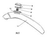
- FIG. 5is a schematic illustration of a partially exploded view of a button actuation assembly implemented in a hand held device according to another embodiment of the invention.
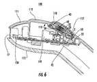
- FIG. 6is a schematic illustration of a cross-sectional view of a hand held device according to another embodiment of the invention.
- FIGS. 7 a - 7 bare schematic illustrations of various views of a button retainer according to an embodiment of the invention.
- FIGS. 8 a - 8 bare schematic illustrations of various views of a button buffer according to an embodiment of the invention.
- FIGS. 9 a - 9 bare schematic illustrations of various views of a button according to an embodiment of the invention.
- FIG. 10is a schematic illustration of a partially exploded cross-sectional view of a hand held barcode reading device according to another embodiment of the invention.
- FIG. 11is a schematic illustration of a partially exploded cross-sectional view of a variation on the hand held barcode reading device of FIG. 10 .
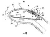
- FIG. 12is a schematic illustration of another embodiment of the invention.
- the button actuation assembly 10for activating a switch 50 according to an embodiment is described.
- the button actuation assembly 10includes a button 40 having an interior side 47 and an exterior side 48 .
- a flexible cantilever 42is provided on the interior side of the button for engaging the switch 50 .
- the flexible cantilever 42is in contact with the switch 50 substantially at all times.
- the flexible cantilever 42bends, and because point P is a fulcrum or pivot point for the button 40 , the transferred force f at the switch 50 is attenuated, i.e. transferred force f is less than the incident force F.
- the at-rest position A (shown in dotted lines) and the pressed-down position B of the button 40are shown in FIG. 3 .
- This attenuating function of the flexible cantilever 42 coupled with both the limiting features of the buffer and the force limiting feature of the flexible cantilever 42protects the switch 50 from being damaged when an excessive force is applied to the button.
- a button retainer 20holds the button 40 , at rest, in a fixed position with respect to the switch 50 so that when the button is pressed, it actuates the switch in a repeatable and consistent manner.
- a bias spring 60is provided between the button retainer 20 and the button 40 for biasing the button away from the switch 50 .
- the bias spring 60may be replaced by another equivalent structure such as a block of a compressible elastomeric material or a molded plastic spring element.
- a button buffer 30 made of a compressible materialis provided between the button 40 and the button retainer 20 to evenly distribute and transfer excessive force applied to button 40 to button retainer 20 .
- the button retainer 20is configured to retain the button 40 and the button buffer 30 in combination with the button retainer 20 itself as an assembly maintaining the button 40 in a desired position with respect to the switch 50 and to ultimately limit the travel of the button 40 when pressed.
- Thismay be achieved in a number of ways.
- the button retainer 20can be attached to another structure 20 a while sandwiching the button 40 and the button buffer 30 between the button retainer 20 and the structure 20 a .
- the structure 20 ashould be a structure that also has a fixed position with respect to the switch 50 .
- An example for such structure 20 awould be a housing for a device within which the switch 50 is provided and the button actuation assembly 10 is incorporated.
- buttons actuation assemblyin which the button retainer 20 retains the button 40 and the button buffer 30 all within itself by utilizing a structure such as a retaining ring 20 b as shown in the cross-sectional view in FIG. 2 .
- This embodimentallows the button actuation assembly to be a standalone assembled unit that can be utilized in any appropriate device.
- the button 40at rest position, is urged away from the switch 50 and against the perimeter rim 117 of the window 115 , as shown in FIG. 5 , by the bias spring 60 .
- the button retainer 20 and the button buffer 30are dimensioned to maintain a space S between the button 40 and the button buffer 30 so that when a user presses the button 40 , the gap S is closed and the button 40 contacts the button buffer 30 .
- the button 40 and the button buffer 30are held snuggly between the perimeter rim 117 of the window 115 and the button retainer 20 at the point P opposite the flexible cantilever 42 , thus forming a pivot point for the button 40 at the point P.
- the buttonwill pivot at the pivot point P and the end near the flexible cantilever 42 closes the space S and causes the flexible cantilever 42 to press down on the switch 50 .
- the assemblymay be configured so that the button does not pivot.
- the buttonmay simply float on the bias spring 60 urged against the perimeter rim 117 maintaining a space between the button 40 and the button buffer 30 all around the perimeter of the button 40 .
- the whole buttonwill move towards the button buffer 30 closing the space S therebetween.
- the button buffer 30when the button contacts the button buffer 30 and is pressed against it the button buffer 30 is compressed and functions to transfer and evenly distribute a portion of the force exerted on the button to button retainer 20 .
- a portion of the force F applied to button 40is absorbed by the flexible cantilever 42 of the button and this remaining force f is transmitted to the switch.
- the transmitted force fis sufficient to activate the switch 50 .
- the flexible cantilever 42 and the button buffer 30in combination attenuates and limits the force F exerted on the button 40 and function to protect the switch 50 and the button actuation assembly 10 from being damaged by excessive force.
- the button buffer 30also functions to limit the travel of the button when pressed. This is particularly beneficial to protect the assembly from damage when an excessive force is applied to the button.
- a bias springis also provided between the button retainer and the button for biasing the button away from the switch.
- a hand held device 100that incorporates an improved switch activating button is disclosed.
- a deviceincludes a housing 110 , a switch 50 provided within the housing for activating a function of the device.
- the switch 50is generally provided on a printed circuit board 55 inside the housing 110 .
- the housing 110can be made of any suitable material, such as a plastic, a metal alloy, or a composite.
- the device 100may have one or more printed circuit boards for the various components and wiring necessary for the hand held device's function.
- a button 40 having a flexible cantilever 42engages the switch 50 via the flexible cantilever.
- a button retainer 20attached to the interior-side 113 of the housing 110 , holds the button 40 , at rest, in a fixed position with respect to the switch 50 .
- the button 40is exposed through a window 115 in the housing.
- the button retainer 20is provided with a receptacle 22 for holding a bias spring 60 that is normally compressed against the underside of the button 40 urging the button upward.
- the bias spring 60normally keeps the pressure off of the switch 50 .
- the bias spring 60 shown in this examplemaybe substituted by other spring-like component such as a block of elastic polymer material.
- the flexible cantilever 42is a cantilevered beam that presses on the switch 50 when the button is pushed. In normal use, when the button is pushed, the flexible cantilever 42 pushes on the switch 50 with a force determined by the flexible cantilever's spring constant and its physical dimensions (i.e. its thickness and length) enough to activate the switch 50 but not hard enough to damage the switch no matter how hard the button is pressed.
- the cantilever beam action of the flexible cantilever 42protects the switch 50 from physical damage because the flexible cantilever 42 will attenuate and limit the impact force that is transmitted to the switch 50 .
- the spring constant of the flexible cantilever 42is a function of the particular material and its dimensions (i.e. its thickness, for example) and one of ordinary skill in the art would be able to select an appropriate material and the dimensions required for a particular application requirement.
- a plasticsuch as acetal, for example, may be used for the button 40 and its flexible cantilever 42 .
- a button buffer 30 made of a compressible elastomeris provided between the button and the button retainer as a shock absorbing layer and to limit the travel of the button 40 when being pressed.
- the button buffer 30absorbs at least a portion of any impact shock transmitting through the button to the button retainer 20 and prevents possible damages to the button retainer.
- the button buffer 30may be made of a compressible elastomer. Some examples of such elastomers are thermoplastic vulcanizates, ethylene propylene diene monomer (EPDM) rubber compounds, and polychloroprene rubber compounds.
- the button buffer 30also works in concert with the flexible cantilever 42 of the button to limit the overall movement of the button and thus attenuate the impact force transmitted to the switch 50 .
- the flexible cantileverWhen a user presses the button, exerting a force on the button, the flexible cantilever attenuates and transfers the force to the switch and activates the switch. Furthermore, the elasticity and compliance of the button buffer provides a softer forgiving feel to the button when the user pushes the button which provides generally more desirable feel to the button.
- the button retainer 20is the stationary structure against which the button 40 is pressed, the button retainer 20 is preferably rigidly fixed in position with respect to the housing 110 . This may be achieved in a number of ways. In the example illustrated in FIG. 4 , the button retainer 20 is affixed to the housing 110 sandwiching the button buffer 30 , the bias spring 60 and the button 40 between the button retainer 20 and the interior-side 113 of the housing 110 . As discussed above, the bias spring 60 may be substituted readily by another equivalent structure such as a block of a compressible elastomer.
- the button 40is exposed through and may even be protruding through the window 115 of the housing 10 but the size of the window 115 opening is smaller than the button 40 so that the perimeter rim 117 of the window 115 retains the button 40 between the housing and the button retainer 20 .
- the window 115 in the housing 110can be simply an opening through which the button is exposed and the user can press the button as shown in FIGS. 4 and 5 .
- the window 115may be covered with a flexible membrane 118 .
- the membraneis flexible so the button can be pressed through it.
- Such flexible membrane 118can either be adhesively or mechanically attached to the housing 110 or integrally molded with the housing 110 .
- a mechanical attachmentcould be achieved, for example, by a tongue-and-groove type of engagement between the perimeter rim 117 of the window 115 and the flexible membrane 118 , by ultrasonically bonding the flexible membrane along the perimeter rim 117 , or combination of both or also in combination with an adhesive.
- the ultrasonic bondingwould only work in an embodiment where the housing 110 is made of a plastic.
- Such flexible membrane 118will prevent water or other liquid from entering through the window and damaging the internal components of the hand held device.
- Some examples of appropriate materials for the flexible membrane 18are the polymer materials discussed above for the button buffer 30 .
- the button retainer 20comprises a base portion 21 that is shaped similar to the outline of the button 40 (shown in FIGS. 9 a - 9 b ).
- the button retainer 20has an opening 24 through which the flexible cantilever 42 of the button 40 extends and engages the switch 50 .
- the receptacle 22 on the button retainer 20holds the bias spring 60 in place between the button retainer and the button 40 .
- a plurality of assembly alignment tabs 26 , 27 , 28are also provided on the button retainer 20 for keeping the components of the button switch actuator assembly, the button retainer 20 , the button buffer 30 , and the button 40 in an alignment.
- the button buffer 30is shaped to have a shape substantially similar to the outline of the button 40 (shown in FIGS. 9 a - 9 b ) so that when the button 40 is pressed, other than the flexible cantilever 42 which contacts the switch 50 , the body of the button 40 comes down on to and only contacts the button buffer 30 .
- the button buffer 30is made of a compressible elastomer, when the button 40 is impacted against a hard surface, such as when the hand held device 100 is dropped, the button buffer 30 cushions and limits the travel of the button 40 and absorbs a portion of the impact shock (the remaining portion of the impact shock being absorbed by the flexible cantilever 42 as it flexes against the switch 50 ).
- the button buffer 30has a first opening 34 corresponding to the opening 24 of the button retainer through which the flexible cantilever 42 of the button extends.
- the button buffer 30also has a second opening 32 through which the receptacle 22 of the button retainer 20 fits when the three components of the button switch actuator assembly is assembled.
- the button buffer 30is provided with a plurality of alignment holes 36 , 37 , 38 that mates with the corresponding alignment tabs 26 , 27 , 28 , respectively, for keeping the button buffer 30 aligned with the button retainer 20 .
- the button 40comprises a main portion 41 and a flexible cantilever 42 .
- the flexible cantilever 42engages the switch 50 .
- the main portion 41 of the buttonhas a central portion 46 that is concave as viewed from the underside of the button 40 for receiving the bias spring 60 .
- the main portion 41also has a rim 44 that has the outline matching those of the button retainer 20 and the button buffer 30 . The rim 44 contacts the button buffer 30 when the button 40 is fully pressed.
- the flexible cantilever 42in this example is formed integrally with the body of the button 40 for engaging the switch 50 .
- the particular dimensions of the flexible cantilever 42is determined by the particular material selected for the button 40 and the particular spring constant desired for a particular application. For example, for a given material, the flexible cantilever 42 maybe made to be thinner to reduce the spring constant and made to be thicker to increase the spring constant.
- the particular spring constant requiredwould be determined by the force required to actuate the particular switch 50 .
- the flexible cantilever 42 illustrated in FIG. 9 ais structured to have three legs 42 a , 42 b , 42 c , rather than being formed as a single solid structure. This is just another example of how the spring constant of the flexible cantilever 42 can be controlled by varying the number and size of the legs.
- button 40 and the button buffer 30are held snuggly between the perimeter rim 117 of the window 115 and the button retainer 20 at the point P opposite the flexible cantilever 42 , thus forming a pivot point for the button 40 at the point P.
- the button 40is normally urged against the perimeter rim 117 of the window 115 by the bias spring 60 but away from the pivot point P, there is a space S between the button 40 and the button buffer 30 .
- the button 40will pivot at the pivot point P and the end near the flexible cantilever 42 gets pushed in closing the space S and bending the flexible cantilever 42 .
- the housing 110maybe a two-piece housing comprising an upper piece 111 and a lower piece 112 where the button retainer 20 is attached to the interior-side 113 of the upper piece 111 and holds the button 40 between the button retainer and the upper piece of the housing.
- FIG. 5is an exploded view of the button switch actuator assembly shown with only the upper piece 111 of the housing 110 .
- the button retainer 20can be attached to the lower piece of the housing.
- the button retainer 220is affixed to the printed circuit board 255 on which the switch 250 is provided.
- the button retainer 220is configured to hold the button buffer 30 , the button 40 and the bias spring 60 within the button retainer 220 itself.
- the assembled printed circuit board 355includes the fully functioning switch 250 and the button switch actuating assembly, the button switch actuating assembly comprising the button retainer 220 , the button buffer 30 , and the button 40 .
- the button 40aligns with the window 215 provided on the housing 210 presenting the button 40 to the user through the window 215 .
- the window 215maybe an opening or the window 215 may be covered with a flexible membrane 218 as shown in FIG. 11 .
- Some examples of appropriate materials for the flexible membrane 218are the polymer materials discussed above for the button buffer 30 .
- the flexible membrane 218may be attached to the housing 210 by the same methods discussed above in reference to the flexible membrane 18 and the housing 10 of the hand held device 100 .
- the hand held devices 100 and 200 of FIGS. 4 , 6 , 10 , and 11may be any type of electronic or electromechanical device in which the button 40 is used to activate the switch 50 for enabling a function of the devices.
- the particular examples in which the inventors have implemented the improved button switch activatoris a hand held barcode reader.
- the hand held devices 100 and 200 of FIGS. 4 , 6 , 10 , and 11are illustrated as examples of a such barcode reader.
- On the printed circuit boards 55 , 255are laser beam sources 170 , 270 , respectively.
- the laser beam sources 170 , 270produces laser beams that propagates through the laser scanning windows 17 , 217 and are used to scan barcodes.
- Photodiodes 130 , 230measure the intensity of the reflected laser beam for decoding the barcode. In use, the user would point the laser scanning windows 17 , 217 at a barcode and press the button 40 .
- FIG. 12a cross-sectional schematic illustration of an embodiment wherein the improved button actuation assembly of the present invention is employed in a camera-based barcode reader 300 is shown.
- the camera-based barcode reader 300includes a housing 310 , a switch 50 provided within the housing for activating a light source 394 for illuminating the barcode.
- the switch 50is generally provided on a printed circuit board 355 inside the housing 310 .
- the barcode reader 300may have one or more printed circuit boards for the various components and wiring necessary for the barcode reader's function.
- the housing 310maybe a two-piece housing comprising an upper piece 311 and a lower piece 312 where the button retainer 20 is attached to the interior-side 313 of the upper piece 311 and holds the button 40 between the button retainer and the upper piece of the housing.
- the button 40engages the switch 50 via the flexible cantilever 42 .
- the button retainer 20attached to the interior-side 313 of the housing 310 , holds the button 40 , at rest, in a fixed position with respect to the switch 50 .
- the button 40is exposed through a window in the housing.
- the bias spring 60normally compressed against the underside of the button 40 and urging the button upward is provided within the receptacle 22 of the button retainer 20 .
- the camera-based barcode reader 300is provided with the light source 394 for illuminating the barcode and a camera module 390 for capturing the image of the illuminated barcode.
- the camera module 390can be a solid state device such as a CCD and may be provided with a lens 392 to help focus on the barcode.
- the divergent light rays 396 from the light source 394 propagating through the window 317is graphically illustrated.
Landscapes
- Push-Button Switches (AREA)
Abstract
Description
Claims (2)
Priority Applications (2)
| Application Number | Priority Date | Filing Date | Title |
|---|---|---|---|
| US11/560,381US7381914B1 (en) | 2006-11-16 | 2006-11-16 | Button actuation assembly |
| US12/103,735US7446276B2 (en) | 2006-11-16 | 2008-04-16 | Button actuation assembly |
Applications Claiming Priority (1)
| Application Number | Priority Date | Filing Date | Title |
|---|---|---|---|
| US11/560,381US7381914B1 (en) | 2006-11-16 | 2006-11-16 | Button actuation assembly |
Related Child Applications (1)
| Application Number | Title | Priority Date | Filing Date |
|---|---|---|---|
| US12/103,735DivisionUS7446276B2 (en) | 2006-11-16 | 2008-04-16 | Button actuation assembly |
Publications (2)
| Publication Number | Publication Date |
|---|---|
| US20080116280A1 US20080116280A1 (en) | 2008-05-22 |
| US7381914B1true US7381914B1 (en) | 2008-06-03 |
Family
ID=39415944
Family Applications (2)
| Application Number | Title | Priority Date | Filing Date |
|---|---|---|---|
| US11/560,381ActiveUS7381914B1 (en) | 2006-11-16 | 2006-11-16 | Button actuation assembly |
| US12/103,735Expired - Fee RelatedUS7446276B2 (en) | 2006-11-16 | 2008-04-16 | Button actuation assembly |
Family Applications After (1)
| Application Number | Title | Priority Date | Filing Date |
|---|---|---|---|
| US12/103,735Expired - Fee RelatedUS7446276B2 (en) | 2006-11-16 | 2008-04-16 | Button actuation assembly |
Country Status (1)
| Country | Link |
|---|---|
| US (2) | US7381914B1 (en) |
Cited By (8)
| Publication number | Priority date | Publication date | Assignee | Title |
|---|---|---|---|---|
| US20080110034A1 (en)* | 2005-09-06 | 2008-05-15 | The Gillette Company | Razors |
| USD589465S1 (en)* | 2007-07-27 | 2009-03-31 | Omron Corporation | Handy switch |
| USD589464S1 (en)* | 2007-07-27 | 2009-03-31 | Omron Corporation | Handy switch |
| US20110073505A1 (en)* | 2009-09-29 | 2011-03-31 | Kurt Stiehl | Button mechanisms for electronic device cases |
| US20120000760A1 (en)* | 2010-06-30 | 2012-01-05 | 3M Innovative Properties Company | Switch system having a button travel limit feature |
| CN102804614A (en)* | 2009-06-18 | 2012-11-28 | 蓝鸟软件株式会社 | Mobile terminal having information recognition module |
| US9224551B2 (en) | 2009-04-09 | 2015-12-29 | Metrologic Instruments, Inc. | Trigger mechanism for hand held devices |
| US11040651B2 (en)* | 2017-01-09 | 2021-06-22 | Ls Automotive Technologies Co., Ltd. | Multifunctional switch device for vehicles |
Families Citing this family (32)
| Publication number | Priority date | Publication date | Assignee | Title |
|---|---|---|---|---|
| DE102004049435B4 (en)* | 2004-10-08 | 2006-11-16 | Zf Friedrichshafen Ag | Button with cable |
| JP2009193773A (en)* | 2008-02-13 | 2009-08-27 | Citizen Electronics Co Ltd | Illuminated push-button switch |
| CN101640138B (en)* | 2008-07-30 | 2011-06-22 | 鸿富锦精密工业(深圳)有限公司 | trigger switch |
| JP4703762B1 (en)* | 2009-12-22 | 2011-06-15 | 株式会社東芝 | Electronics |
| KR101107016B1 (en)* | 2010-09-02 | 2012-01-25 | (주)블루버드 소프트 | Mobile terminal |
| US8994799B2 (en) | 2011-07-26 | 2015-03-31 | ByteLight, Inc. | Method and system for determining the position of a device in a light based positioning system using locally stored maps |
| US8866391B2 (en) | 2011-07-26 | 2014-10-21 | ByteLight, Inc. | Self identifying modulated light source |
| US9287976B2 (en) | 2011-07-26 | 2016-03-15 | Abl Ip Holding Llc | Independent beacon based light position system |
| US9787397B2 (en) | 2011-07-26 | 2017-10-10 | Abl Ip Holding Llc | Self identifying modulated light source |
| US8416290B2 (en) | 2011-07-26 | 2013-04-09 | ByteLight, Inc. | Method and system for digital pulse recognition demodulation |
| US8334898B1 (en) | 2011-07-26 | 2012-12-18 | ByteLight, Inc. | Method and system for configuring an imaging device for the reception of digital pulse recognition information |
| US8436896B2 (en) | 2011-07-26 | 2013-05-07 | ByteLight, Inc. | Method and system for demodulating a digital pulse recognition signal in a light based positioning system using a Fourier transform |
| US9723676B2 (en) | 2011-07-26 | 2017-08-01 | Abl Ip Holding Llc | Method and system for modifying a beacon light source for use in a light based positioning system |
| US9444547B2 (en) | 2011-07-26 | 2016-09-13 | Abl Ip Holding Llc | Self-identifying one-way authentication method using optical signals |
| US8520065B2 (en) | 2011-07-26 | 2013-08-27 | ByteLight, Inc. | Method and system for video processing to determine digital pulse recognition tones |
| US9418115B2 (en) | 2011-07-26 | 2016-08-16 | Abl Ip Holding Llc | Location-based mobile services and applications |
| JP5842527B2 (en)* | 2011-10-14 | 2016-01-13 | オムロン株式会社 | Pushbutton switch and electronic device using the same |
| GB2500422B8 (en)* | 2012-03-22 | 2015-04-22 | Cheng Uei Prec Ind Co Ltd | Switch apparatus |
| US9459160B2 (en) | 2012-06-13 | 2016-10-04 | Microsoft Technology Licensing, Llc | Input device sensor configuration |
| US9684382B2 (en) | 2012-06-13 | 2017-06-20 | Microsoft Technology Licensing, Llc | Input device configuration having capacitive and pressure sensors |
| US10578499B2 (en) | 2013-02-17 | 2020-03-03 | Microsoft Technology Licensing, Llc | Piezo-actuated virtual buttons for touch surfaces |
| US20140232679A1 (en)* | 2013-02-17 | 2014-08-21 | Microsoft Corporation | Systems and methods to protect against inadvertant actuation of virtual buttons on touch surfaces |
| US9705600B1 (en) | 2013-06-05 | 2017-07-11 | Abl Ip Holding Llc | Method and system for optical communication |
| WO2015077767A1 (en) | 2013-11-25 | 2015-05-28 | Daniel Ryan | System and method for communication with a mobile device via a positioning system including rf communication devices and modulated beacon light sources |
| US9448631B2 (en) | 2013-12-31 | 2016-09-20 | Microsoft Technology Licensing, Llc | Input device haptics and pressure sensing |
| US10416799B2 (en) | 2015-06-03 | 2019-09-17 | Microsoft Technology Licensing, Llc | Force sensing and inadvertent input control of an input device |
| US10222889B2 (en) | 2015-06-03 | 2019-03-05 | Microsoft Technology Licensing, Llc | Force inputs and cursor control |
| US10061385B2 (en) | 2016-01-22 | 2018-08-28 | Microsoft Technology Licensing, Llc | Haptic feedback for a touch input device |
| WO2021042031A1 (en)* | 2019-08-30 | 2021-03-04 | The Johns Hopkins University | Smart fretboard |
| US11289195B2 (en)* | 2020-08-09 | 2022-03-29 | Kevin Patel | System for remote medical care |
| CN113161167B (en)* | 2021-01-13 | 2024-04-05 | 河南平高电气股份有限公司 | Electrical switch spring operating mechanism |
| WO2024242817A2 (en)* | 2023-05-23 | 2024-11-28 | Itt Manufacturing Enterprises Llc | Button assembly with a modular button and sleeve having an infinitely rotational cable exit |
Citations (6)
| Publication number | Priority date | Publication date | Assignee | Title |
|---|---|---|---|---|
| US6002093A (en) | 1998-08-21 | 1999-12-14 | Dell Usa, L.P. | Button with flexible cantilever |
| US20030080007A1 (en)* | 2001-10-26 | 2003-05-01 | Lau Kwok Din | Disk security device |
| US20040182685A1 (en)* | 2003-01-31 | 2004-09-23 | Kinichi Tsunemoto | Dual switch for selective removal of recording medium from compound device |
| US20050099393A1 (en) | 2001-03-09 | 2005-05-12 | Johnson Peter W. | Button assembly for input devices |
| US20050145473A1 (en)* | 2004-01-06 | 2005-07-07 | Yu-Ting Ni | Microswitch |
| US20060273784A1 (en)* | 2005-06-03 | 2006-12-07 | Arquimedes Godoy | Rotary position sensor |
Family Cites Families (4)
| Publication number | Priority date | Publication date | Assignee | Title |
|---|---|---|---|---|
| AU466541B2 (en)* | 1972-08-10 | 1975-10-30 | Oak Industries Inc | Low profile keyboard switch |
| GB1441196A (en)* | 1973-07-27 | 1976-06-30 | Oak Industries Inc | Pushbutton switch |
| DE60304409T2 (en)* | 1997-04-28 | 2006-10-19 | Idec Izumi Corp. | Tactile switch, device for operation and keyboard with this switch |
| US6054662A (en)* | 1999-04-26 | 2000-04-25 | Dell Usa L.P. | Torsion enhanced return device for electronic system push button |
- 2006
- 2006-11-16USUS11/560,381patent/US7381914B1/enactiveActive
- 2008
- 2008-04-16USUS12/103,735patent/US7446276B2/ennot_activeExpired - Fee Related
Patent Citations (6)
| Publication number | Priority date | Publication date | Assignee | Title |
|---|---|---|---|---|
| US6002093A (en) | 1998-08-21 | 1999-12-14 | Dell Usa, L.P. | Button with flexible cantilever |
| US20050099393A1 (en) | 2001-03-09 | 2005-05-12 | Johnson Peter W. | Button assembly for input devices |
| US20030080007A1 (en)* | 2001-10-26 | 2003-05-01 | Lau Kwok Din | Disk security device |
| US20040182685A1 (en)* | 2003-01-31 | 2004-09-23 | Kinichi Tsunemoto | Dual switch for selective removal of recording medium from compound device |
| US20050145473A1 (en)* | 2004-01-06 | 2005-07-07 | Yu-Ting Ni | Microswitch |
| US20060273784A1 (en)* | 2005-06-03 | 2006-12-07 | Arquimedes Godoy | Rotary position sensor |
Cited By (16)
| Publication number | Priority date | Publication date | Assignee | Title |
|---|---|---|---|---|
| US20080110034A1 (en)* | 2005-09-06 | 2008-05-15 | The Gillette Company | Razors |
| US7810243B2 (en)* | 2005-09-06 | 2010-10-12 | The Gillette Company | Razors |
| US20100325872A1 (en)* | 2005-09-06 | 2010-12-30 | Fred Schnak | Razors |
| US9409302B2 (en) | 2005-09-06 | 2016-08-09 | The Gillette Company | Razors |
| US8561301B2 (en) | 2005-09-06 | 2013-10-22 | The Gillette Company | Razors |
| USD589465S1 (en)* | 2007-07-27 | 2009-03-31 | Omron Corporation | Handy switch |
| USD589464S1 (en)* | 2007-07-27 | 2009-03-31 | Omron Corporation | Handy switch |
| US9224551B2 (en) | 2009-04-09 | 2015-12-29 | Metrologic Instruments, Inc. | Trigger mechanism for hand held devices |
| CN102804614A (en)* | 2009-06-18 | 2012-11-28 | 蓝鸟软件株式会社 | Mobile terminal having information recognition module |
| CN102804614B (en)* | 2009-06-18 | 2014-12-03 | 蓝鸟软件株式会社 | Mobile terminal having information recognition module |
| US8167126B2 (en) | 2009-09-29 | 2012-05-01 | Apple Inc. | Button mechanisms for electronic device cases |
| US20110073505A1 (en)* | 2009-09-29 | 2011-03-31 | Kurt Stiehl | Button mechanisms for electronic device cases |
| US8404990B2 (en)* | 2010-06-30 | 2013-03-26 | 3M Innovative Properties Company | Switch system having a button travel limit feature |
| AU2011276994B2 (en)* | 2010-06-30 | 2014-08-14 | 3M Innovative Properties Company | Switch system having a button travel limit feature |
| US20120000760A1 (en)* | 2010-06-30 | 2012-01-05 | 3M Innovative Properties Company | Switch system having a button travel limit feature |
| US11040651B2 (en)* | 2017-01-09 | 2021-06-22 | Ls Automotive Technologies Co., Ltd. | Multifunctional switch device for vehicles |
Also Published As
| Publication number | Publication date |
|---|---|
| US20080190750A1 (en) | 2008-08-14 |
| US7446276B2 (en) | 2008-11-04 |
| US20080116280A1 (en) | 2008-05-22 |
Similar Documents
| Publication | Publication Date | Title |
|---|---|---|
| US7381914B1 (en) | Button actuation assembly | |
| TWI324782B (en) | Keyboard assembly | |
| US9224551B2 (en) | Trigger mechanism for hand held devices | |
| US7423229B2 (en) | Light guiding plate and a keystroke module for use therewith | |
| US8097822B2 (en) | Light emitting key structure | |
| US20160306437A1 (en) | Depressible Keys with Decoupled Electrical and Mechanical Functionality | |
| US6984797B2 (en) | Push-button switch | |
| US8493742B2 (en) | Push-button switch assembly and electronic device with same | |
| TW201931408A (en) | Optical keyswitch | |
| US6529370B1 (en) | Keyboard switch | |
| EP2323150A1 (en) | Keyboard structure | |
| US20070007118A1 (en) | Keypad assembly | |
| TW201108286A (en) | Keyboard having backlight function | |
| MXPA06009864A (en) | Touch key assembly for a mobile terminal. | |
| US20080000765A1 (en) | Composite switch | |
| US7851718B2 (en) | Electronic equipment | |
| US10236140B2 (en) | Illuminated dual pressure sensing key | |
| JP2009277611A (en) | Contact retention sheet with light guide | |
| CN101329958A (en) | Movable contact body and switch using same | |
| JP4703552B2 (en) | Illumination member for switch and switch device using the same | |
| JP2008293465A (en) | Image input device | |
| TWI672717B (en) | Keyswitch structure | |
| KR101635207B1 (en) | Shock absorbing switch for mobile phone | |
| CN113661553A (en) | Key switch and lighting switch device | |
| JP2007123193A (en) | Key switch |
Legal Events
| Date | Code | Title | Description |
|---|---|---|---|
| AS | Assignment | Owner name:METROLOGIC INSTRUMENTS, INC., NEW JERSEY Free format text:ASSIGNMENT OF ASSIGNORS INTEREST;ASSIGNORS:PLESKO, GEORGE A.;WANG, YUAN-HUA;REEL/FRAME:018525/0837;SIGNING DATES FROM 20061025 TO 20061106 Owner name:METROLOGIC INSTRUMENTS, INC., NEW JERSEY Free format text:ASSIGNMENT OF ASSIGNORS INTEREST;ASSIGNORS:PLESKO, GEORGE A.;WANG, YUAN-HUA;REEL/FRAME:018526/0089;SIGNING DATES FROM 20061025 TO 20061106 | |
| AS | Assignment | Owner name:MORGAN STANLEY & CO. INCORPORATED, NEW YORK Free format text:FIRST LIEN IP SECURITY AGREEMENT;ASSIGNORS:METROLOGIC INSTRUMENTS, INC.;METEOR HOLDING CORP.;OMNIPLANAR, INC.;REEL/FRAME:018942/0315 Effective date:20061221 Owner name:MORGAN STANLEY & CO. INCORPORATED, NEW YORK Free format text:SECOND LIEN IP SECURITY AGREEMENT;ASSIGNORS:METROLOGIC INSTRUMENTS, INC.;METEOR HOLDING CORP.;OMNIPLANAR, INC.;REEL/FRAME:018942/0671 Effective date:20061221 Owner name:MORGAN STANLEY & CO. INCORPORATED,NEW YORK Free format text:FIRST LIEN IP SECURITY AGREEMENT;ASSIGNORS:METROLOGIC INSTRUMENTS, INC.;METEOR HOLDING CORP.;OMNIPLANAR, INC.;REEL/FRAME:018942/0315 Effective date:20061221 Owner name:MORGAN STANLEY & CO. INCORPORATED,NEW YORK Free format text:SECOND LIEN IP SECURITY AGREEMENT;ASSIGNORS:METROLOGIC INSTRUMENTS, INC.;METEOR HOLDING CORP.;OMNIPLANAR, INC.;REEL/FRAME:018942/0671 Effective date:20061221 | |
| STCF | Information on status: patent grant | Free format text:PATENTED CASE | |
| FEPP | Fee payment procedure | Free format text:PAYOR NUMBER ASSIGNED (ORIGINAL EVENT CODE: ASPN); ENTITY STATUS OF PATENT OWNER: LARGE ENTITY | |
| AS | Assignment | Owner name:METROLOGIC INSTRUMENTS, INC., NEW JERSEY Free format text:FIRST LIEN INTELLECTUAL PROPERTY SECURITY AGREEMENT RELEASE;ASSIGNOR:MORGAN STANLEY & CO. INCORPORATED;REEL/FRAME:023085/0754 Effective date:20080701 Owner name:METEOR HOLDING CORPORATION, NEW JERSEY Free format text:FIRST LIEN INTELLECTUAL PROPERTY SECURITY AGREEMENT RELEASE;ASSIGNOR:MORGAN STANLEY & CO. INCORPORATED;REEL/FRAME:023085/0754 Effective date:20080701 Owner name:OMNIPLANAR, INC., NEW JERSEY Free format text:FIRST LIEN INTELLECTUAL PROPERTY SECURITY AGREEMENT RELEASE;ASSIGNOR:MORGAN STANLEY & CO. INCORPORATED;REEL/FRAME:023085/0754 Effective date:20080701 Owner name:METROLOGIC INSTRUMENTS, INC., NEW JERSEY Free format text:SECOND LIEN INTELLECTUAL PROPERTY SECURITY AGREEMENT RELEASE;ASSIGNOR:MORGAN STANLEY & CO. INCORPORATED;REEL/FRAME:023085/0809 Effective date:20080701 Owner name:METEOR HOLDING CORPORATION, NEW JERSEY Free format text:SECOND LIEN INTELLECTUAL PROPERTY SECURITY AGREEMENT RELEASE;ASSIGNOR:MORGAN STANLEY & CO. INCORPORATED;REEL/FRAME:023085/0809 Effective date:20080701 Owner name:OMNIPLANAR, INC., NEW JERSEY Free format text:SECOND LIEN INTELLECTUAL PROPERTY SECURITY AGREEMENT RELEASE;ASSIGNOR:MORGAN STANLEY & CO. INCORPORATED;REEL/FRAME:023085/0809 Effective date:20080701 Owner name:METROLOGIC INSTRUMENTS, INC.,NEW JERSEY Free format text:FIRST LIEN INTELLECTUAL PROPERTY SECURITY AGREEMENT RELEASE;ASSIGNOR:MORGAN STANLEY & CO. INCORPORATED;REEL/FRAME:023085/0754 Effective date:20080701 Owner name:METEOR HOLDING CORPORATION,NEW JERSEY Free format text:FIRST LIEN INTELLECTUAL PROPERTY SECURITY AGREEMENT RELEASE;ASSIGNOR:MORGAN STANLEY & CO. INCORPORATED;REEL/FRAME:023085/0754 Effective date:20080701 Owner name:OMNIPLANAR, INC.,NEW JERSEY Free format text:FIRST LIEN INTELLECTUAL PROPERTY SECURITY AGREEMENT RELEASE;ASSIGNOR:MORGAN STANLEY & CO. INCORPORATED;REEL/FRAME:023085/0754 Effective date:20080701 Owner name:METROLOGIC INSTRUMENTS, INC.,NEW JERSEY Free format text:SECOND LIEN INTELLECTUAL PROPERTY SECURITY AGREEMENT RELEASE;ASSIGNOR:MORGAN STANLEY & CO. INCORPORATED;REEL/FRAME:023085/0809 Effective date:20080701 Owner name:METEOR HOLDING CORPORATION,NEW JERSEY Free format text:SECOND LIEN INTELLECTUAL PROPERTY SECURITY AGREEMENT RELEASE;ASSIGNOR:MORGAN STANLEY & CO. INCORPORATED;REEL/FRAME:023085/0809 Effective date:20080701 Owner name:OMNIPLANAR, INC.,NEW JERSEY Free format text:SECOND LIEN INTELLECTUAL PROPERTY SECURITY AGREEMENT RELEASE;ASSIGNOR:MORGAN STANLEY & CO. INCORPORATED;REEL/FRAME:023085/0809 Effective date:20080701 | |
| FPAY | Fee payment | Year of fee payment:4 | |
| FPAY | Fee payment | Year of fee payment:8 | |
| MAFP | Maintenance fee payment | Free format text:PAYMENT OF MAINTENANCE FEE, 12TH YEAR, LARGE ENTITY (ORIGINAL EVENT CODE: M1553); ENTITY STATUS OF PATENT OWNER: LARGE ENTITY Year of fee payment:12 |