US7380828B2 - Stationary wheel hub - Google Patents
Stationary wheel hubDownload PDFInfo
- Publication number
- US7380828B2 US7380828B2US11/076,222US7622205AUS7380828B2US 7380828 B2US7380828 B2US 7380828B2US 7622205 AUS7622205 AUS 7622205AUS 7380828 B2US7380828 B2US 7380828B2
- Authority
- US
- United States
- Prior art keywords
- steering column
- steering
- aperture
- column assembly
- engaging end
- Prior art date
- Legal status (The legal status is an assumption and is not a legal conclusion. Google has not performed a legal analysis and makes no representation as to the accuracy of the status listed.)
- Expired - Fee Related, expires
Links
Images


Classifications
- B—PERFORMING OPERATIONS; TRANSPORTING
- B62—LAND VEHICLES FOR TRAVELLING OTHERWISE THAN ON RAILS
- B62D—MOTOR VEHICLES; TRAILERS
- B62D1/00—Steering controls, i.e. means for initiating a change of direction of the vehicle
- B62D1/02—Steering controls, i.e. means for initiating a change of direction of the vehicle vehicle-mounted
- B62D1/16—Steering columns
- B—PERFORMING OPERATIONS; TRANSPORTING
- B60—VEHICLES IN GENERAL
- B60K—ARRANGEMENT OR MOUNTING OF PROPULSION UNITS OR OF TRANSMISSIONS IN VEHICLES; ARRANGEMENT OR MOUNTING OF PLURAL DIVERSE PRIME-MOVERS IN VEHICLES; AUXILIARY DRIVES FOR VEHICLES; INSTRUMENTATION OR DASHBOARDS FOR VEHICLES; ARRANGEMENTS IN CONNECTION WITH COOLING, AIR INTAKE, GAS EXHAUST OR FUEL SUPPLY OF PROPULSION UNITS IN VEHICLES
- B60K35/00—Instruments specially adapted for vehicles; Arrangement of instruments in or on vehicles
- B60K35/50—Instruments characterised by their means of attachment to or integration in the vehicle
- B—PERFORMING OPERATIONS; TRANSPORTING
- B60—VEHICLES IN GENERAL
- B60K—ARRANGEMENT OR MOUNTING OF PROPULSION UNITS OR OF TRANSMISSIONS IN VEHICLES; ARRANGEMENT OR MOUNTING OF PLURAL DIVERSE PRIME-MOVERS IN VEHICLES; AUXILIARY DRIVES FOR VEHICLES; INSTRUMENTATION OR DASHBOARDS FOR VEHICLES; ARRANGEMENTS IN CONNECTION WITH COOLING, AIR INTAKE, GAS EXHAUST OR FUEL SUPPLY OF PROPULSION UNITS IN VEHICLES
- B60K35/00—Instruments specially adapted for vehicles; Arrangement of instruments in or on vehicles
- B60K35/60—Instruments characterised by their location or relative disposition in or on vehicles
- B—PERFORMING OPERATIONS; TRANSPORTING
- B62—LAND VEHICLES FOR TRAVELLING OTHERWISE THAN ON RAILS
- B62D—MOTOR VEHICLES; TRAILERS
- B62D1/00—Steering controls, i.e. means for initiating a change of direction of the vehicle
- B62D1/02—Steering controls, i.e. means for initiating a change of direction of the vehicle vehicle-mounted
- B62D1/04—Hand wheels
- B—PERFORMING OPERATIONS; TRANSPORTING
- B60—VEHICLES IN GENERAL
- B60K—ARRANGEMENT OR MOUNTING OF PROPULSION UNITS OR OF TRANSMISSIONS IN VEHICLES; ARRANGEMENT OR MOUNTING OF PLURAL DIVERSE PRIME-MOVERS IN VEHICLES; AUXILIARY DRIVES FOR VEHICLES; INSTRUMENTATION OR DASHBOARDS FOR VEHICLES; ARRANGEMENTS IN CONNECTION WITH COOLING, AIR INTAKE, GAS EXHAUST OR FUEL SUPPLY OF PROPULSION UNITS IN VEHICLES
- B60K2360/00—Indexing scheme associated with groups B60K35/00 or B60K37/00 relating to details of instruments or dashboards
- B60K2360/77—Instrument locations other than the dashboard
- B60K2360/782—Instrument locations other than the dashboard on the steering wheel
Definitions
- the inventionrelates to a steering column of a vehicle and more particularly to a steering column supporting a hub portion that for supporting vehicle accessories wherein the hub is generally surrounded by a steering wheel.
- a steering columnusually extends into the vehicle passenger compartment under the instrument panel.
- One or more gagesare mounted, or clustered, on the instrument panel.
- gages which are not included on the instrument panelhave been fixedly mounted to the steering column structure. Examples of these arrangements are shown in U.S. Pat. Nos. 1,795,566; 1,944,905; 2,465,825; and 4,368,454.
- the inventionprovides a steering column assembly for a vehicle and a method for manufacturing the steering column assembly.
- the steering column assemblyincludes a steering column member having an aperture extending along an axis.
- the steering column assemblyalso includes a steering shaft rotatably disposed at least partially in the aperture.
- the steering shaftincludes a steering wheel engaging end axially spaced from the aperture.
- the steering column assemblyalso includes a supporting member for supporting a vehicle accessory. The supporting member is cantilevered from the steering column member and cooperates with the steering column member to define a groove substantially surrounding the steering wheel engaging end.
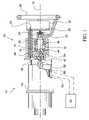
- FIG. 1is a left-hand, partial cross-sectional view of a first exemplary embodiment of the invention wherein the partial cross-section is taken a longitudinal axis of a steering column;
- FIG. 2is a front view of the first exemplary embodiment of the invention
- FIG. 3is a perspective view of a steering-by-wire system incorporating the first exemplary embodiment of the invention.
- a steering column assembly 10in a first exemplary embodiment of the invention, includes a steering column member 12 having an aperture 14 extending along an axis 16 .
- the steering column member 12is a tilt housing.
- the steering column assembly 10also includes a steering shaft 18 rotatably disposed at least partially in the aperture 14 .
- First and second bearings 44 , 46are disposed in the aperture 16 and support the steering shaft 18 in rotation relative to the steering column member 12 .
- the steering shaft 18includes a steering wheel engaging end 20 axially spaced from the aperture 14 .
- the steering column assembly 10also includes a supporting member 22 for supporting a vehicle accessory.
- the vehicle accessorycan be an actuator, such as push-button 48 or a gage 50 .
- the push-button 48can control an operation associated with the vehicle such as activating or deactivating lights, adjusting music parameters from a sound system of the vehicle, adjusting cruise control of the vehicle, or any other controllable operation associated with the vehicle.
- the gage 50can provide a visual indication of any condition sensed by a sensor associated with the vehicle such as oil pressure, engine speed (rpm), vehicle speed, amount of fuel, or any other condition sensed by a sensor associated with the vehicle.
- the supporting member 22 of the first exemplary embodimentsupports a plurality of a vehicle accessories.
- the supporting member 22is cantilevered from the steering column member 12 and cooperates with the steering column member 12 to define a groove 24 substantially surrounding the steering wheel engaging end 20 .
- the supporting member 22includes a beam portion 26 and a plate portion 28 .
- the beam portion 26extends parallel to the steering shaft 18 and away from the steering column member 12 , beyond the steering wheel engaging end 20 .
- the plate portion 28extends substantially perpendicular to the beam portion 26 towards the axis 16 such that the steering wheel engaging end 20 is rotatably disposed between the plate portion 28 and the steering column member 12 along the axis 16 .
- the groove 24extends transverse to the axis 16 .
- the steering column member 12includes a second aperture 30 and the beam portion 26 extends in the second aperture 30 .
- the beam portion 26defines an interior 32 and the plate portion 28 includes an aperture 34 communicating with the interior 32 .
- Electrical or mechanical connections, such as wires or cables, extending from the vehicle accessory supported on the plate portion 28can extend through the aperture 34 , the interior 32 , and the aperture 30 to remote locations.
- the steering column assembly 10also includes a bracket 36 and a steering wheel 38 .
- the bracket 36is engaged with the steering wheel engaging end 20 and extends out of the groove 24 and around the supporting member 22 .
- the steering wheel 38is engaged with the bracket 36 and encircles at least a portion of the supporting member 22 . As shown in FIG. 2 , the steering wheel 38 encircles the supporting member 28 . As shown in FIG. 1 , the steering wheel 38 is axial spaced from the supporting member 28 .
- the bracket 36 and the supporting member 22cooperate to limit rotation of the steering shaft 18 .
- the steering shaft 18is rotatable less than 360 degrees.
- the bracket 36will contact the supporting member 22 during rotation an be prevented from further rotation.
- the size of the beam portion 26can be minimized to maximize the extent of rotation of steering shaft 18 .
- the driver of the vehicleturns the steering wheel 38 , which turns the shafts 18 and 52 .
- the position sensors 56 and 58sense rotation of the shaft 52 and communicates sensed conditions to the controller 60 .
- the controller 60receives signals from the position sensors 56 and 58 corresponding to sensed conditions and controls the pump 66 to pump fluid and also controls the valve 68 to direct fluid to the side of the piston corresponding to the desired direction of vehicle turning.
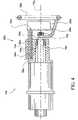
- a non-tiltable steering column assembly 10 aincludes a steering column member 12 a having an aperture 14 a extending along an axis 16 a .
- the steering column assembly 10 aalso includes a steering shaft 18 a rotatably disposed at least partially in the aperture 14 a .
- the steering shaft 18 aincludes a steering wheel engaging end 20 a axially spaced from the aperture 14 a .
- the steering column assembly 10 aalso includes a supporting member 22 a for supporting a vehicle accessory.
- the supporting member 22 ais cantilevered from the steering column member 12 a and cooperates with the steering column member 12 a to define a groove 24 a substantially surrounding the steering wheel engaging end 20 a .
- the supporting member 22 aincludes a beam portion 26 a disposed in an aperture 30 a and a plate portion 28 a .
- the beam portion 26 adefines an interior 32 a and the plate portion 28 a includes an aperture 34 a communicating with the interior 32 a .
- the steering column assembly 10 aalso includes a bracket 36 a and a steering wheel 38 a.
Landscapes
- Engineering & Computer Science (AREA)
- Chemical & Material Sciences (AREA)
- Combustion & Propulsion (AREA)
- Transportation (AREA)
- Mechanical Engineering (AREA)
- Steering Controls (AREA)
Abstract
Description
Claims (14)
Priority Applications (1)
| Application Number | Priority Date | Filing Date | Title |
|---|---|---|---|
| US11/076,222US7380828B2 (en) | 2005-03-09 | 2005-03-09 | Stationary wheel hub |
Applications Claiming Priority (1)
| Application Number | Priority Date | Filing Date | Title |
|---|---|---|---|
| US11/076,222US7380828B2 (en) | 2005-03-09 | 2005-03-09 | Stationary wheel hub |
Publications (2)
| Publication Number | Publication Date |
|---|---|
| US20060202462A1 US20060202462A1 (en) | 2006-09-14 |
| US7380828B2true US7380828B2 (en) | 2008-06-03 |
Family
ID=36970033
Family Applications (1)
| Application Number | Title | Priority Date | Filing Date |
|---|---|---|---|
| US11/076,222Expired - Fee RelatedUS7380828B2 (en) | 2005-03-09 | 2005-03-09 | Stationary wheel hub |
Country Status (1)
| Country | Link |
|---|---|
| US (1) | US7380828B2 (en) |
Cited By (14)
| Publication number | Priority date | Publication date | Assignee | Title |
|---|---|---|---|---|
| US20070000346A1 (en)* | 2005-06-06 | 2007-01-04 | Songwe Jr N | Steering wheel system |
| US20090152840A1 (en)* | 2007-12-15 | 2009-06-18 | Hyundai Motor Company | Vehicle steering system including irrotational airbag module |
| US20090242314A1 (en)* | 2008-04-01 | 2009-10-01 | International Truck Intellectual Property Company, Llc | Steering assembly mechanism for adjusting a steering wheel from asymmetry to symmetry |
| US20110285118A1 (en)* | 2007-08-29 | 2011-11-24 | Ferrari S.P.A. | Road vehicle front airbag |
| US20130298716A1 (en)* | 2012-05-11 | 2013-11-14 | Cnh America Llc | Steering device for a vehicle |
| US20170106894A1 (en)* | 2015-10-20 | 2017-04-20 | Steering Solutions Ip Holding Corporation | Steering column with stationary hub |
| US9845106B2 (en) | 2015-08-31 | 2017-12-19 | Steering Solutions Ip Holding Corporation | Overload protection for belt drive mechanism |
| US10029642B2 (en) | 2016-03-18 | 2018-07-24 | Hyundai America Technical Center, Inc | Enhanced steering system utilizing fixed dab for occupant protection in frontal impacts with laterial loading |
| US10144382B2 (en) | 2015-12-15 | 2018-12-04 | Hyundai America Technical Center, Inc. | Steering column system for vehicle occupant safety |
| US10160473B2 (en) | 2016-09-13 | 2018-12-25 | Steering Solutions Ip Holding Corporation | Steering column decoupling system |
| US10589774B2 (en) | 2015-05-01 | 2020-03-17 | Steering Solutions Ip Holding Corporation | Counter rotation steering wheel |
| US10766518B2 (en) | 2015-06-25 | 2020-09-08 | Steering Solutions Ip Holding Corporation | Rotation control system for a steering wheel and method |
| US11378597B2 (en) | 2019-11-29 | 2022-07-05 | Steering Solutions Ip Holding Corporation | Closed-loop compensation of current measurement offset errors in alternating current motor drives |
| US11434954B2 (en)* | 2016-08-08 | 2022-09-06 | Thyssenkrupp Presta Ag | Rotational bearing arrangement for a steering column of a motor vehicle |
Families Citing this family (1)
| Publication number | Priority date | Publication date | Assignee | Title |
|---|---|---|---|---|
| AT522442B1 (en) | 2019-11-08 | 2020-11-15 | Ivan Tochev | Arrangement of a steering device |
Citations (20)
| Publication number | Priority date | Publication date | Assignee | Title |
|---|---|---|---|---|
| US1795566A (en) | 1927-12-12 | 1931-03-10 | Maccomb Richard Albert | Pilot stand |
| US1944905A (en) | 1932-04-06 | 1934-01-30 | Rowell Elijah Hendrix | Instrument panel |
| US2465825A (en) | 1947-03-24 | 1949-03-29 | Tucker Corp | Steering wheel mounted instrument panel |
| US2622690A (en) | 1949-02-25 | 1952-12-23 | Barenyi Bela | Steering device for motor vehicles |
| US3734051A (en) | 1971-08-05 | 1973-05-22 | E Dahl | Vehicle wheel position indicator |
| US3910597A (en) | 1972-12-05 | 1975-10-07 | Nissan Motor | Vehicle steering column-steering wheel assembly |
| US4013034A (en) | 1975-03-10 | 1977-03-22 | Incom International Inc. | Steering control device |
| US4368454A (en) | 1978-09-27 | 1983-01-11 | Bernd Pilatzki | Steering device with dished impact plate for automotive vehicles |
| US4429588A (en)* | 1980-02-29 | 1984-02-07 | Klockner-Humboldt-Deutz Aktiengesellschaft | Steering wheel for a motor vehicle, particularly for a tractor |
| US4485371A (en) | 1981-04-14 | 1984-11-27 | Aisin Seiki Kabushiki Kaisha | Steering wheel system |
| US4603599A (en) | 1984-05-28 | 1986-08-05 | Nissan Motor Co., Ltd. | Steering system equipped with steering wheel center pad anti-rotation mechanism |
| US4625578A (en) | 1984-01-18 | 1986-12-02 | Nihon Plast Co., Ltd. | Steering wheel assembly |
| US4674352A (en)* | 1983-12-29 | 1987-06-23 | Kabushiki Kaisha Tokai Rika Denki Seisakusho | Steering wheel device |
| US4771650A (en) | 1986-06-25 | 1988-09-20 | Daimler-Benz Aktiengesellschaft | Steering wheel arrangement for vehicles |
| US5072628A (en)* | 1989-09-19 | 1991-12-17 | Oki T Jack | Multi function steering mechanism for a motor vehicle |
| US5465632A (en)* | 1994-05-05 | 1995-11-14 | Oki; T. Jack | Steering wheel having a stationary display |
| US6109651A (en) | 1997-05-24 | 2000-08-29 | Trw Automotive Safety Systems Gmbh | Device for fastening a steering wheel to a steering column |
| US6142504A (en) | 1996-10-29 | 2000-11-07 | Trw Inc. | Steering wheel and air bag assembly attachment to a steering shaft |
| US6145402A (en)* | 1997-11-21 | 2000-11-14 | Yazaki Corporation | Steering module |
| US20040168848A1 (en)* | 1998-08-13 | 2004-09-02 | Hubert Bohner | Vehicle steering system |
- 2005
- 2005-03-09USUS11/076,222patent/US7380828B2/ennot_activeExpired - Fee Related
Patent Citations (20)
| Publication number | Priority date | Publication date | Assignee | Title |
|---|---|---|---|---|
| US1795566A (en) | 1927-12-12 | 1931-03-10 | Maccomb Richard Albert | Pilot stand |
| US1944905A (en) | 1932-04-06 | 1934-01-30 | Rowell Elijah Hendrix | Instrument panel |
| US2465825A (en) | 1947-03-24 | 1949-03-29 | Tucker Corp | Steering wheel mounted instrument panel |
| US2622690A (en) | 1949-02-25 | 1952-12-23 | Barenyi Bela | Steering device for motor vehicles |
| US3734051A (en) | 1971-08-05 | 1973-05-22 | E Dahl | Vehicle wheel position indicator |
| US3910597A (en) | 1972-12-05 | 1975-10-07 | Nissan Motor | Vehicle steering column-steering wheel assembly |
| US4013034A (en) | 1975-03-10 | 1977-03-22 | Incom International Inc. | Steering control device |
| US4368454A (en) | 1978-09-27 | 1983-01-11 | Bernd Pilatzki | Steering device with dished impact plate for automotive vehicles |
| US4429588A (en)* | 1980-02-29 | 1984-02-07 | Klockner-Humboldt-Deutz Aktiengesellschaft | Steering wheel for a motor vehicle, particularly for a tractor |
| US4485371A (en) | 1981-04-14 | 1984-11-27 | Aisin Seiki Kabushiki Kaisha | Steering wheel system |
| US4674352A (en)* | 1983-12-29 | 1987-06-23 | Kabushiki Kaisha Tokai Rika Denki Seisakusho | Steering wheel device |
| US4625578A (en) | 1984-01-18 | 1986-12-02 | Nihon Plast Co., Ltd. | Steering wheel assembly |
| US4603599A (en) | 1984-05-28 | 1986-08-05 | Nissan Motor Co., Ltd. | Steering system equipped with steering wheel center pad anti-rotation mechanism |
| US4771650A (en) | 1986-06-25 | 1988-09-20 | Daimler-Benz Aktiengesellschaft | Steering wheel arrangement for vehicles |
| US5072628A (en)* | 1989-09-19 | 1991-12-17 | Oki T Jack | Multi function steering mechanism for a motor vehicle |
| US5465632A (en)* | 1994-05-05 | 1995-11-14 | Oki; T. Jack | Steering wheel having a stationary display |
| US6142504A (en) | 1996-10-29 | 2000-11-07 | Trw Inc. | Steering wheel and air bag assembly attachment to a steering shaft |
| US6109651A (en) | 1997-05-24 | 2000-08-29 | Trw Automotive Safety Systems Gmbh | Device for fastening a steering wheel to a steering column |
| US6145402A (en)* | 1997-11-21 | 2000-11-14 | Yazaki Corporation | Steering module |
| US20040168848A1 (en)* | 1998-08-13 | 2004-09-02 | Hubert Bohner | Vehicle steering system |
Cited By (19)
| Publication number | Priority date | Publication date | Assignee | Title |
|---|---|---|---|---|
| US20070000346A1 (en)* | 2005-06-06 | 2007-01-04 | Songwe Jr N | Steering wheel system |
| US8794667B2 (en)* | 2007-08-29 | 2014-08-05 | Ferrari S.P.A. | Road vehicle front airbag |
| US20110285118A1 (en)* | 2007-08-29 | 2011-11-24 | Ferrari S.P.A. | Road vehicle front airbag |
| US20090152840A1 (en)* | 2007-12-15 | 2009-06-18 | Hyundai Motor Company | Vehicle steering system including irrotational airbag module |
| US7931296B2 (en)* | 2007-12-15 | 2011-04-26 | Hyundai Motor Company | Vehicle steering system including irrotational airbag module |
| US20090242314A1 (en)* | 2008-04-01 | 2009-10-01 | International Truck Intellectual Property Company, Llc | Steering assembly mechanism for adjusting a steering wheel from asymmetry to symmetry |
| US7753409B2 (en)* | 2008-04-01 | 2010-07-13 | Navistar Canada, Inc. | Steering assembly mechanism for adjusting a steering wheel from asymmetry to symmetry |
| US9090282B2 (en)* | 2012-05-11 | 2015-07-28 | Cnh Industrial America Llc | Steering device for a vehicle |
| US20130298716A1 (en)* | 2012-05-11 | 2013-11-14 | Cnh America Llc | Steering device for a vehicle |
| US10589774B2 (en) | 2015-05-01 | 2020-03-17 | Steering Solutions Ip Holding Corporation | Counter rotation steering wheel |
| US10766518B2 (en) | 2015-06-25 | 2020-09-08 | Steering Solutions Ip Holding Corporation | Rotation control system for a steering wheel and method |
| US9845106B2 (en) | 2015-08-31 | 2017-12-19 | Steering Solutions Ip Holding Corporation | Overload protection for belt drive mechanism |
| US20170106894A1 (en)* | 2015-10-20 | 2017-04-20 | Steering Solutions Ip Holding Corporation | Steering column with stationary hub |
| US10160472B2 (en)* | 2015-10-20 | 2018-12-25 | Steering Solutions Ip Holding Corporation | Steering column with stationary hub |
| US10144382B2 (en) | 2015-12-15 | 2018-12-04 | Hyundai America Technical Center, Inc. | Steering column system for vehicle occupant safety |
| US10029642B2 (en) | 2016-03-18 | 2018-07-24 | Hyundai America Technical Center, Inc | Enhanced steering system utilizing fixed dab for occupant protection in frontal impacts with laterial loading |
| US11434954B2 (en)* | 2016-08-08 | 2022-09-06 | Thyssenkrupp Presta Ag | Rotational bearing arrangement for a steering column of a motor vehicle |
| US10160473B2 (en) | 2016-09-13 | 2018-12-25 | Steering Solutions Ip Holding Corporation | Steering column decoupling system |
| US11378597B2 (en) | 2019-11-29 | 2022-07-05 | Steering Solutions Ip Holding Corporation | Closed-loop compensation of current measurement offset errors in alternating current motor drives |
Also Published As
| Publication number | Publication date |
|---|---|
| US20060202462A1 (en) | 2006-09-14 |
Similar Documents
| Publication | Publication Date | Title |
|---|---|---|
| US7380828B2 (en) | Stationary wheel hub | |
| US6688645B2 (en) | Turn-limited column assembly | |
| EP3476692B1 (en) | "steer by wire" road vehicle steering system provided with a telescopic support element for the steering wheel | |
| US8162706B2 (en) | Watercraft steering system, and watercraft | |
| EP1923306A2 (en) | Steering system for a watercraft | |
| JP4327637B2 (en) | Outboard motor steering device and outboard motor | |
| CN112703145A (en) | Steering column and steer-by-wire system | |
| US9114823B2 (en) | Actuating device employed in steering system for vehicle | |
| JP4277798B2 (en) | Electric power steering device | |
| US6112844A (en) | Power steering for motor vehicles | |
| US20080272582A1 (en) | Energy absorbing steering system | |
| US12325464B2 (en) | Adjustable steering column for a vehicle | |
| JP3867055B2 (en) | Outboard motor steering system | |
| EP3401189A1 (en) | Electric power steering assembly and system with anti-rotation coupler | |
| EP1697201B1 (en) | Method and computer product in a steering arrangement for a vehicle | |
| EP1031491A1 (en) | Improvements in or relating to vehicle steering | |
| KR20230023152A (en) | Electric power steering apparatus for vehicle | |
| JP2010167828A (en) | Rudder angle ratio variable system | |
| JP4379442B2 (en) | Electric power steering device | |
| GB2449340A (en) | Torque sensor in a power assisted vehicle steering column | |
| JP2007216720A (en) | Electric power steering device | |
| JP4602108B2 (en) | Working vehicle | |
| KR102858583B1 (en) | Electric Power Steering Apparatus for Vehicle | |
| US20230159084A1 (en) | Steer by wire type steering apparatus | |
| JP2007145162A (en) | Outboard motor steering system |
Legal Events
| Date | Code | Title | Description |
|---|---|---|---|
| AS | Assignment | Owner name:DELPHI TECHNOLOGIES, INC., MICHIGAN Free format text:ASSIGNMENT OF ASSIGNORS INTEREST;ASSIGNORS:MENJAK, RATKO;KAUFMANN, TIMOTHY W.;GILLMAN, STEPHEN V.;AND OTHERS;REEL/FRAME:016373/0728;SIGNING DATES FROM 20050222 TO 20050224 | |
| STCF | Information on status: patent grant | Free format text:PATENTED CASE | |
| AS | Assignment | Owner name:GM GLOBAL TECHNOLOGY OPERATIONS, INC., MICHIGAN Free format text:ASSIGNMENT OF ASSIGNORS INTEREST;ASSIGNOR:DELPHI TECHNOLOGIES, INC.;REEL/FRAME:023449/0065 Effective date:20091002 Owner name:GM GLOBAL TECHNOLOGY OPERATIONS, INC.,MICHIGAN Free format text:ASSIGNMENT OF ASSIGNORS INTEREST;ASSIGNOR:DELPHI TECHNOLOGIES, INC.;REEL/FRAME:023449/0065 Effective date:20091002 | |
| AS | Assignment | Owner name:GM GLOBAL TECHNOLOGY OPERATIONS, INC.,MICHIGAN Free format text:ASSIGNMENT OF ASSIGNORS INTEREST;ASSIGNOR:DELPHI TECHNOLOGIES, INC.;REEL/FRAME:023988/0754 Effective date:20091002 Owner name:UNITED STATES DEPARTMENT OF THE TREASURY,DISTRICT Free format text:SECURITY AGREEMENT;ASSIGNOR:GM GLOBAL TECHNOLOGY OPERATIONS, INC.;REEL/FRAME:023990/0349 Effective date:20090710 Owner name:UAW RETIREE MEDICAL BENEFITS TRUST,MICHIGAN Free format text:SECURITY AGREEMENT;ASSIGNOR:GM GLOBAL TECHNOLOGY OPERATIONS, INC.;REEL/FRAME:023990/0831 Effective date:20090710 Owner name:GM GLOBAL TECHNOLOGY OPERATIONS, INC., MICHIGAN Free format text:ASSIGNMENT OF ASSIGNORS INTEREST;ASSIGNOR:DELPHI TECHNOLOGIES, INC.;REEL/FRAME:023988/0754 Effective date:20091002 Owner name:UNITED STATES DEPARTMENT OF THE TREASURY, DISTRICT Free format text:SECURITY AGREEMENT;ASSIGNOR:GM GLOBAL TECHNOLOGY OPERATIONS, INC.;REEL/FRAME:023990/0349 Effective date:20090710 Owner name:UAW RETIREE MEDICAL BENEFITS TRUST, MICHIGAN Free format text:SECURITY AGREEMENT;ASSIGNOR:GM GLOBAL TECHNOLOGY OPERATIONS, INC.;REEL/FRAME:023990/0831 Effective date:20090710 | |
| AS | Assignment | Owner name:GM GLOBAL TECHNOLOGY OPERATIONS, INC., MICHIGAN Free format text:RELEASE BY SECURED PARTY;ASSIGNOR:UAW RETIREE MEDICAL BENEFITS TRUST;REEL/FRAME:025386/0503 Effective date:20101026 Owner name:GM GLOBAL TECHNOLOGY OPERATIONS, INC., MICHIGAN Free format text:RELEASE BY SECURED PARTY;ASSIGNOR:UNITED STATES DEPARTMENT OF THE TREASURY;REEL/FRAME:025386/0591 Effective date:20100420 | |
| FPAY | Fee payment | Year of fee payment:4 | |
| AS | Assignment | Owner name:PACIFIC CENTURY MOTORS, INC., CHINA Free format text:ASSIGNMENT OF ASSIGNORS INTEREST;ASSIGNOR:GM GLOBAL TECHNOLOGY OPERATIONS, INC.;REEL/FRAME:027842/0918 Effective date:20101130 Owner name:GM GLOBAL TECHNOLOGY OPERATIONS, INC., MICHIGAN Free format text:ASSIGNMENT OF ASSIGNORS INTEREST;ASSIGNOR:GM GLOBAL TECHNOLOGY OPERATIONS, INC.;REEL/FRAME:027842/0918 Effective date:20101130 | |
| AS | Assignment | Owner name:STEERING SOLUTIONS IP HOLDING CORPORATION, MICHIGA Free format text:ASSIGNMENT OF ASSIGNORS INTEREST;ASSIGNORS:PACIFIC CENTURY MOTORS, INC.;NEXTEER (BEIJING) TECHNOLOGY CO., LTD.;REEL/FRAME:027870/0666 Effective date:20120126 | |
| FPAY | Fee payment | Year of fee payment:8 | |
| FEPP | Fee payment procedure | Free format text:MAINTENANCE FEE REMINDER MAILED (ORIGINAL EVENT CODE: REM.); ENTITY STATUS OF PATENT OWNER: LARGE ENTITY | |
| LAPS | Lapse for failure to pay maintenance fees | Free format text:PATENT EXPIRED FOR FAILURE TO PAY MAINTENANCE FEES (ORIGINAL EVENT CODE: EXP.); ENTITY STATUS OF PATENT OWNER: LARGE ENTITY | |
| STCH | Information on status: patent discontinuation | Free format text:PATENT EXPIRED DUE TO NONPAYMENT OF MAINTENANCE FEES UNDER 37 CFR 1.362 | |
| FP | Lapsed due to failure to pay maintenance fee | Effective date:20200603 |