US7380055B2 - Apparatus and method in a cached raid controller utilizing a solid state backup device for improving data availability time - Google Patents
Apparatus and method in a cached raid controller utilizing a solid state backup device for improving data availability timeDownload PDFInfo
- Publication number
- US7380055B2 US7380055B2US11/054,203US5420305AUS7380055B2US 7380055 B2US7380055 B2US 7380055B2US 5420305 AUS5420305 AUS 5420305AUS 7380055 B2US7380055 B2US 7380055B2
- Authority
- US
- United States
- Prior art keywords
- volatile memory
- controller
- main power
- posted
- power
- Prior art date
- Legal status (The legal status is an assumption and is not a legal conclusion. Google has not performed a legal analysis and makes no representation as to the accuracy of the status listed.)
- Active, expires
Links
Images


Classifications
- G—PHYSICS
- G06—COMPUTING OR CALCULATING; COUNTING
- G06F—ELECTRIC DIGITAL DATA PROCESSING
- G06F11/00—Error detection; Error correction; Monitoring
- G06F11/07—Responding to the occurrence of a fault, e.g. fault tolerance
- G06F11/14—Error detection or correction of the data by redundancy in operation
- G06F11/1402—Saving, restoring, recovering or retrying
- G06F11/1415—Saving, restoring, recovering or retrying at system level
- G06F11/1441—Resetting or repowering
- G—PHYSICS
- G06—COMPUTING OR CALCULATING; COUNTING
- G06F—ELECTRIC DIGITAL DATA PROCESSING
- G06F1/00—Details not covered by groups G06F3/00 - G06F13/00 and G06F21/00
- G06F1/26—Power supply means, e.g. regulation thereof
- G06F1/32—Means for saving power
- G06F1/3203—Power management, i.e. event-based initiation of a power-saving mode
- G06F1/3234—Power saving characterised by the action undertaken
- G06F1/325—Power saving in peripheral device
- G06F1/3268—Power saving in hard disk drive
- Y—GENERAL TAGGING OF NEW TECHNOLOGICAL DEVELOPMENTS; GENERAL TAGGING OF CROSS-SECTIONAL TECHNOLOGIES SPANNING OVER SEVERAL SECTIONS OF THE IPC; TECHNICAL SUBJECTS COVERED BY FORMER USPC CROSS-REFERENCE ART COLLECTIONS [XRACs] AND DIGESTS
- Y02—TECHNOLOGIES OR APPLICATIONS FOR MITIGATION OR ADAPTATION AGAINST CLIMATE CHANGE
- Y02D—CLIMATE CHANGE MITIGATION TECHNOLOGIES IN INFORMATION AND COMMUNICATION TECHNOLOGIES [ICT], I.E. INFORMATION AND COMMUNICATION TECHNOLOGIES AIMING AT THE REDUCTION OF THEIR OWN ENERGY USE
- Y02D10/00—Energy efficient computing, e.g. low power processors, power management or thermal management
- Y—GENERAL TAGGING OF NEW TECHNOLOGICAL DEVELOPMENTS; GENERAL TAGGING OF CROSS-SECTIONAL TECHNOLOGIES SPANNING OVER SEVERAL SECTIONS OF THE IPC; TECHNICAL SUBJECTS COVERED BY FORMER USPC CROSS-REFERENCE ART COLLECTIONS [XRACs] AND DIGESTS
- Y02—TECHNOLOGIES OR APPLICATIONS FOR MITIGATION OR ADAPTATION AGAINST CLIMATE CHANGE
- Y02D—CLIMATE CHANGE MITIGATION TECHNOLOGIES IN INFORMATION AND COMMUNICATION TECHNOLOGIES [ICT], I.E. INFORMATION AND COMMUNICATION TECHNOLOGIES AIMING AT THE REDUCTION OF THEIR OWN ENERGY USE
- Y02D30/00—Reducing energy consumption in communication networks
- Y02D30/50—Reducing energy consumption in communication networks in wire-line communication networks, e.g. low power modes or reduced link rate
Definitions
- the present inventionrelates in general to the field of mass storage controllers, and particularly to write-caching controllers that use a non-volatile backup device to avoid loss of cached user data.
- Redundant Array of Inexpensive Disksystems have become the predominant form of mass storage systems in most computer systems today that are used in applications that require high performance, large amounts of storage, and/or high data availability, such as transaction processing, banking, medical applications, database servers, internet servers, mail servers, scientific computing, and a host of other applications.
- a RAID controllercontrols a group of multiple physical disk drives in such a manner as to present a single logical disk drive (or multiple logical disk drives) to a computer operating system.
- RAID controllersemploy the techniques of data striping and data redundancy to increase performance and data availability.
- RAID controllersAn important characteristic of RAID controllers, particularly in certain applications such as transaction processing or real-time data capture of large data streams, is to provide fast write performance.
- the overall performance of the computer systemmay be greatly improved if the write latency of the RAID controller is relatively small.
- the write latencyis the time the RAID controller takes to complete a write request from the computer system.
- RAID controllersinclude a relatively large cache memory for caching user data from the disk drives. Caching the data enables the RAID controller to quickly return data to the computer system if the requested data is in the cache memory since the RAID controller does not have to perform the lengthy operation of reading the data from the disk drives.
- the cache memorymay also be employed to reduce write request latency by enabling what is commonly referred to as posted-write operations. In a posted-write operation, the RAID controller reads the data specified by the computer system from the computer system into the RAID controller's cache memory and then immediately notifies the computer system that the write request is complete, even though the RAID controller has not yet written the data to the disk drives.
- Posted-writesare particularly useful in RAID controllers, since in some redundant RAID levels a read-modify-write operation to the disk drives must be performed in order to accomplish the system write request, i.e., not only must the specified system data be written to the disk drives, but some of the disk drives may also have to be read before the user data and redundant data can be written to the disks, which may make the write latency of a RAID controller even longer than a non-RAID controller.
- posted-write operationsmake the system vulnerable to data loss in the event of a power failure. This is because the cache memory is a volatile memory that loses the user data when power is lost and the data has not yet been written to the disk drives.
- some RAID controllersinclude a battery to continue to provide power to the cache memory in the event of a loss of main power.
- the systemautomatically notifies a system administrator who attempts to restore power to the system.
- the batterygreatly reduces the likelihood that user data will be lost, because the charge on the battery is finite, the possibility still exists that the battery power will run out before main power can be restored, in which case the user data will be lost.
- other RAID controllersinclude some form of non-volatile memory, such as a FLASH memory or small disk drive.
- the RAID controllercopies the cache memory contents to the FLASH memory and then disables battery power.
- main poweris restored, the RAID controller restores the contents of the cache memory prior to the main power outage from the FLASH memory so that the posted-writes can be completed and the user data can be made available again.
- the time required to restore the cache memory contents from the FLASH memorymay be relatively lengthy, particularly, on the order of minutes.
- a RAID controllerthat has 512 MB of cache memory and current FLASH memories that provide a sustained read rate of approximately 9 MB/second.
- the time required to restore the cache memory from FLASH memoryis approximately one minute; that is, one minute more is required to boot the RAID controller after main power is restored. This is one minute more that the user data is not available to the host computer system, which in some user applications may translate to thousands of dollars of lost income.
- the additional time spent restoring the cache memory from FLASHmay cause the predetermined timeout values of some server applications to be exceeded, thereby causing the application to fail.
- the restore time—and therefore user data unavailability time—is even greater for RAID controllers with larger cache memories than the example; and, the problem will be exacerbated even further as RAID controller cache memory sizes increase, which appears to be a definite trend.
- the present inventionprovides an apparatus and method for reducing the data unavailability time after a loss of main power in a cached RAID controller by continuing to supply battery power to the volatile cache memory even after the volatile memory has been backed up to the non-volatile memory, and foregoing performing a restore from the non-volatile memory to the volatile memory if it determines that the battery was able to continue supplying power to the volatile memory until the main power was restored.
- the present inventionprovides a mass storage controller for providing improved data availability.
- the controllerincludes a volatile memory, for storing posted-write data, and a non-volatile memory, coupled to the volatile memory, for backing up the posted-write data from the volatile memory, in response to a loss of main power.
- the controlleralso includes a battery, coupled to supply power to the volatile memory in response to the loss of main power, and an indicator, for indicating whether the battery continued to supply power to the volatile memory until the main power was restored.
- the controlleralso includes control logic, coupled to the indicator, configured to forego restoring the posted-write data to the volatile memory from the non-volatile memory in response to the main power being restored, if the indicator indicates the battery continued to supply power to the volatile memory until the main power was restored.
- the present inventionprovides a method for improving data availability in a redundant array of disks (RAID) controller having a volatile memory for storing posted-write data, a non-volatile memory, and a battery for providing power to the controller in response to loss of main power to the controller.
- the methodincludes backing up the posted-write data from the volatile memory to the non-volatile memory, in response to the loss of main power.
- the methodalso includes determining whether the battery sustained the posted-write data in the volatile memory until the main power is restored, and restoring the posted-write data to the volatile memory from the non-volatile memory, in response to the main power being restored, only if the battery did not sustain the posted-write data in the volatile memory until the main power is restored.
- the present inventionprovides an apparatus for improving data availability in a write-caching controller having a volatile memory for caching posted-write data, a non-volatile memory to which a back up of the posted-write data is performed after a main power failure, and a battery for providing power while the backup is being performed.
- the apparatusincludes the battery attempting to continue to provide power to the volatile memory after the backup is complete and until the main power is restored.
- the apparatusfurther includes a storage element that stores an indication of whether the battery successfully continued to provide power to the volatile memory until the main power was restored.
- the apparatusalso includes control logic, coupled to the storage element, which restores the posted-write data from the non-volatile memory to the volatile memory when the main is restored, but only if the indication indicates the battery did not continue to provide power to the volatile memory until the main power was restored.
- FIG. 1is a block diagram illustrating a mass storage controller according to the present invention.
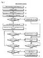
- FIG. 2is a flowchart illustrating operation of the controller of FIG. 1 .
- FIG. 1a block diagram illustrating a mass storage controller 100 , such as a RAID controller, according to the present invention is shown.
- the controller 100may be one of a pair of active-active redundant fault-tolerant RAID controllers for providing high data availability.
- the controller 100includes a disk interface 128 for interfacing to disk drives or other mass storage devices, including but not limited to, tape drives and optical storage devices, such as CDROM or DVD drives.
- the disk drivesstore the user data.
- the disk interface 128may include, but is not limited to, the following interfaces: Fibre Channel, Small Computer Systems Interface (SCSI), Advanced Technology Attachment (ATA), Serial Attached SCSI (SAS), Serial Advanced Technology Attachment (SATA), Ethernet, Infiniband, HIPPI, ESCON, or FICON.
- the controller 100reads and writes data from or to the disk drives in response to I/O requests received from host computers.
- the controller 100also includes a host interface 126 for interfacing with host computers.
- the controller 100is a local bus-based controller, such as a controller that plugs into, or is integrated into, a local I/O bus of the host computer system, such as a PCI, PCI-X, CompactPCI, PCI-Express, PCI-X2, EISA, VESA, VME, RapidIO, AGP, ISA, 3GIO, HyperTransport, Futurebus, MultiBus, or any other local bus.
- the host interface 126comprises a local bus interface of the local bus type.
- the controller 100is a standalone controller in a separate enclosure from the host computers that issue I/O requests to the controller 100 .
- the controller 100may be part of a storage area network (SAN).
- the host interface 126may comprise various interfaces such as Fibre Channel, Ethernet, Infiniband, SCSI, HIPPI, Token Ring, Arcnet, FDDI, LocalTalk, ESCON, FICON, ATM, SAS, SATA, and the like.
- the controller 100also includes a battery 112 for supplying power to the controller 100 in the event of a loss of main power, as described in more detail below.
- the batteryis re-charged via a re-charge signal 132 from the main power supply.
- the battery 112may be disabled by the backup/restore manager 124 (discussed below) via a disable signal 136 or by a micro-CPLD 134 (also discussed below) via a second disable signal 138 .
- the controller 100also includes a volatile memory 102 , or cache memory 102 .
- the volatile memory 102is volatile because it ceases to store its data when it is not powered.
- the volatile memory 102comprises dynamic random access memory (DRAM), which includes a self-refresh mode. When the DRAM is placed into self-refresh mode, the DRAM consumes less power than when not operating in self-refresh mode.
- the volatile memory 102may include other types of volatile memory, such as static random access memory (SRAM).
- the volatile memory 102is employed by the controller 100 to buffer data transferred between the hosts and disks.
- the controller 100transfers the data from the host via the host interface 126 into the volatile memory 102 and subsequently transfers the data from the volatile memory 102 via the disk interface 128 to the disks.
- the controller 100transfers the data from the disks via the disk interface 128 to the volatile memory 102 and subsequently transfers the data from the volatile memory 102 via the host interface 126 to the host.
- the volatile memory 102is used by the controller 100 to perform write-caching of data.
- the controller 100transfers the data from the host via the host interface 126 into the volatile memory 102 and subsequently transfers the data from the volatile memory 102 via the disk interface 128 to the disks. Normally, the controller 100 does not indicate to the host that the write request is complete until the data is actually written to disk. However, if configured to do so, the controller 100 may cache the data in the volatile memory 102 and indicate to the host that the write request is complete before the data is actually written to the disk, and subsequently write, or flush, the data to disk. This operation is referred to as write-caching, or may also be referred to as a posted-write operation. The data associated with a posted-write operation is referred to as posted-write data.
- posted-write datais data stored in the volatile memory 102 that has not yet been written to disk but concerning which the controller 100 has told the host that the write operation has completed.
- the posted-write data as referred to hereinmay refer to control information required to write the data to disk, including but not limited to, the logical block addresses and disk drive unit numbers to which the data must be written, and information specifying whether the data is part of a RAID array with a RAID level requiring redundant data that also must be written to disk to be generated based on the posted-write data.
- the volatile memory 102may also be used by the controller 100 to perform read-caching of data, i.e., to provide requested data to the hosts from the volatile memory 102 , rather than from the disks, if the data is already present in the volatile memory 102 because of a previous read request of the same data. Finally, the controller 100 may use the volatile memory 102 for buffering redundant RAID data generated for writing to the disks.
- the controller 100also includes a non-volatile memory 104 .
- the non-volatile memory 104is non-volatile because it continues to store its data when it is not powered.
- the non-volatile memory 104comprises a Compact FLASH memory.
- the non-volatile memory 104comprises a micro-disk drive.
- the non-volatile memory 104is used by the controller 100 to backup the contents, particularly the posted-write data, of the volatile memory 102 in response to a loss of main power so that when main power returns the posted-write data may be restored from the non-volatile memory 104 to the volatile memory 102 .
- the restore operationmay be lengthy, and until the data is restored to the volatile memory 102 the user data is not available to the hosts.
- the present inventionprovides an apparatus and method for selectively foregoing the restore operation if it is determined that the battery was able to maintain the integrity of the posted-write data in the volatile memory 102 until main power returned, thereby making the user data available to the hosts sooner than if the restore operation were performed, as described in detail below.
- the controller 100also includes a processor 108 for executing programs to control the transfer of data between the disk drives and the hosts.
- the processor 108receives commands from the hosts and responsively issues commands to the disk interface 128 to accomplish data transfers with the disk drives.
- the processor 108may also perform storage controller functions such as RAID control, logical block translation, buffer management, and data caching.
- the processor 108selectively instructs the backup/restore manager 124 to perform or not to perform a restore of the volatile memory 102 to the non-volatile memory 104 based on whether the battery 112 was able to continue supplying power to the volatile memory 102 throughout the main power outage, referred to herein as a selective restore feature.
- the controller 100also includes a selective restore feature enable flag 118 .
- the usermay provide input to enable or disable the selective restore feature.
- the user selectionis stored in the selective restore feature enable flag 118 .
- the selective restore feature enable flag 118is stored in a memory coupled to the processor 108 used for storing program instructions executed by the processor 108 ; however, other embodiments may store the selective restore feature enable flag 118 in other storage locations, such as a discrete register or in the volatile memory 102 .
- One advantage of the ability for the user to disable the selective restore featureis that it may reduce the likelihood of user data loss in the event of two main power losses within a period of time that is short relative to the battery 112 recharge time as follows. When a main power outage occurs, a considerable amount of the battery 112 power is typically used to perform the backup to the non-volatile memory 104 . If the selective restore feature is enabled, more of the battery 112 power will be consumed by powering the volatile memory 102 with battery 112 power. Once main power is restored, the battery 112 may be recharged, but the recharge may require a relatively long length of time—perhaps on the order of hours if the battery 112 has been fully discharged.
- the battery 112has not been recharged sufficiently to perform a backup to the non-volatile memory 104 when a second main power outage occurs, user data may be lost if posted-writes are pending.
- the useris given the choice between potentially faster data availability time or lower risk of data loss in the event of two or more main power outages within a period of time that is short relative to the battery 112 recharge time.
- the brown-out timer 116gives the user even further control over this question by enabling the user to specify a length of time to consume more battery 112 power by continuing to power the volatile memory 102 after it has been backed up to the non-volatile memory 104 .
- the controller 100also includes a micro-CPLD 134 .
- the micro-CPLD 134comprises a complex programmable logic device (CPLD) that consumes very low power.
- CPLDcomplex programmable logic device
- other circuitsmay be employed to perform the functions described herein that are performed by the micro-CPLD 134 , such as custom integrated circuits or discrete components.
- the micro-CPLD 134includes a data good indicator 122 .
- the data good indicator 122may be read by the processor 108 and written by a backup/restore manager circuit 124 which is described below.
- the micro-CPLD 134is configured such that when it is powered up, the data good indicator 122 resets to a predetermined value. In one embodiment, the data good indicator 122 power-up resets to a Boolean value of zero.
- the power-off threshold of the micro-CPLD 134is at least as high as the power threshold at which the volatile memory 102 begins to lose its data. As described below, when main power is lost, the backup/restore manager 124 writes a value into the data good indicator 122 different from the power-up reset value.
- the processor 108will read the power-up reset value from the data good indicator 122 rather than the value written by the backup/restore manager 124 . Consequently, the processor 108 will determine that the volatile memory 102 must be restored from the non-volatile memory 104 . However, if the processor 108 reads from the data good indicator 122 the value written by the backup/restore manager 124 , then the processor 108 will determine that it can forego restoring the volatile memory 102 thereby making the user data available to the hosts sooner, as described in detail below.
- the micro-CPLD 134also includes a brown-out timer 116 .
- the brown-out timer 116is a timer that may be started running by the backup/restore manager 124 . In one embodiment, the user may specify the expiration time of the brown-out timer 116 . If the selective restore feature flag 118 is enabled, then the battery 112 will be used to continue to power the volatile memory 102 until the brown-out timer 116 expires. Thus, the brown-out timer 116 may be used to reduce the likelihood that posted-write data will be lost in the event of back-to-back main power losses, as described above with respect to the selective restore feature flag 118 .
- the controller 100also includes a backup/restore manager and bus bridge circuit 124 , coupled to the processor 108 , micro-CPLD 134 , volatile memory 102 , non-volatile memory 104 , host interface 126 , and disk interface 128 .
- the backup/restore manager 124receives a main power present signal 114 that indicates whether the main power supply is supplying power to the controller 100 .
- the backup/restore manager and bus bridge circuit 124is a custom large scale integrated circuit.
- the bus bridge 124bridges the volatile memory 102 bus, the non-volatile memory 104 , the processor 108 bus (which in one embodiment is a Pentium processor bus), and the host interface 126 and disk interface 128 buses (which in one embodiment are PCI-X buses).
- the bus bridge 124includes a memory controller for controlling the volatile memory 102 and the non-volatile memory 104 .
- the backup/restore manager 124includes a direct memory access controller (DMAC) used to copy the data from the volatile memory 102 to the non-volatile memory 104 during the backup operation.
- DMACdirect memory access controller
- FIG. 2a flowchart illustrating operation of the controller 100 of FIG. 1 is shown. Flow begins at block 202 .
- the backup/restore manager 124detects a loss of main power via the main power present signal 114 . In response, the backup/restore manager 124 causes the battery 112 to provide power to the other circuits of the controller 100 , and in particular to the backup/restore manager 124 , the volatile memory 102 , the non-volatile memory 104 , and the micro-CPLD 134 . Flow proceeds to block 204 .
- the backup/restore manager 124sets the data good indicator 122 to a predetermined value.
- the predetermined valueis different from the value the data good indicator 122 is cleared to in response to a power-on reset.
- the data good indicator 122is a single bit in a register of the micro-CPLD 134 which power-on resets to a Boolean zero value, and the predetermined value to which the backup/restore manager 124 writes the data good indicator 122 is a Boolean one value.
- the registerstores a longer data word which power-on resets to a Boolean zero value
- the predetermined value to which the backup/restore manager 124 writes the data good indicator 122is a predetermined signature value known by the software executed by the processor 108 .
- the backup/restore manager 124starts the brown-out timer 116 running.
- the controller 100receives input from the user specifying the expiration time of the brown-out timer 116 , prior to the loss of main power. Flow proceeds to block 208 .
- the backup/restore manager 124backs up the volatile memory 102 contents to the non-volatile memory 104 .
- the backup/restore manager 124backs up the volatile memory 102 only if there is posted-write data in the volatile memory 102 , i.e., only if the volatile memory 102 is dirty.
- the backup/restore manager 124copies only the posted-write data to the non-volatile memory 104 .
- the backup/restore manager 124simply copies an image of the volatile memory 102 to the non-volatile memory 104 . Flow proceeds to decision block 212 .
- the backup/restore manager 124determines whether the selective restore feature is enabled by examining the selective restore feature enable flag 118 . In one embodiment, the controller 100 receives input from the user enabling or disabling the selective restore feature, prior to the loss of main power. If the feature is disabled, flow proceeds to block 234 ; otherwise, flow proceeds to block 214 .
- the backup/restore manager 124places the volatile memory 102 into self-refresh mode via signal 106 in order to reduce the drain on the battery 112 .
- Flowproceeds to block 216 .
- the backup/restore manager 124disables battery power to all circuits except the volatile memory 102 and the micro-CPLD 134 to further reduce drain on the battery 112 .
- Flowproceeds to decision block 218 .
- the micro-CPLD 134determines whether the brown-out timer 116 expired. If so, flow proceeds to block 236 ; otherwise, flow proceeds to decision block 222 .
- decision block 224as long as the main power is not restored, flow returns to decision block 218 ; however, when the main power is restored, flow proceeds to decision block 226 .
- the processor 108boots up in response to the main power being restored, and determines whether the data good indicator 122 is set to the predetermined value. If so, flow proceeds to block 232 , thereby foregoing the restore operation; otherwise, flow proceeds to block 228 to perform the restore operation.
- the processor 108makes additional determinations at decision block 226 to decide whether to proceed to block 228 to perform the restore operation, such as whether the non-volatile memory 104 is present; whether a backup operation to the non-volatile memory 104 (such as the backup started at block 208 ) is in progress, and if not, whether the backup operation completed successfully; and whether the data backed up into the non-volatile memory 104 is valid.
- the controller 100does not perform a restore from non-volatile memory 104 unless a non-volatile memory 104 is present, a backup was successfully completed, and the information backed up into the non-volatile memory 104 is valid.
- the non-volatile memory 104may be a field-replaceable unit; consequently, when main power is restored and the processor 108 reboots, if the processor 108 determines the non-volatile memory 104 is not present, no restore is performed.
- the controller 100maintains a flag in a separate small non-volatile memory (in one embodiment a CMOS NVRAM) indicating whether or not a backup of the volatile memory 102 to the non-volatile memory 104 was performed. One reason the controller 100 may not have performed a backup is because at the time main power was lost, the volatile memory 102 was not dirty with posted-write data.
- the backup/restore manager 124writes signature information into the non-volatile memory 104 after successful completion of a backup operation.
- the processor 108determines the signature information in the non-volatile memory 104 is not good, then it is assume the posted-write data backed up to the non-volatile memory 104 is not valid, and does not perform a restore operation.
- the processor 108instructs the backup/restore manager 124 to restore the volatile memory 102 from the non-volatile memory 104 . That is, the backup/restore manager 124 copies from the non-volatile memory 104 to the volatile memory 102 the data that was backed up at block 208 . At this point, the user data is now available to the host computers. In one embodiment, when the processor 108 reboots, it takes the volatile memory 102 out of self-refresh mode. Flow proceeds to block 232 .
- the processor 108Once the processor 108 has booted up, it writes the posted-write data to disk. If block 232 was arrived at because the data good indicator 122 was set to the predetermined value, i.e., if the battery 112 maintained the integrity of the volatile memory 102 such that the restore operation at block 228 was not performed, then the user data is available as soon as the processor 108 boots up.
- the controller 100 of the present inventionmay potentially make the user data available to the hosts sooner than in a conventional controller that does not have the selective restore feature of the present invention by an amount equal to the restore operation time. As discussed above, the restore operation time may be significant. Flow ends at block 232 .
- the backup/restore manager 124disables the battery 112 power to all circuits of the controller 100 via disable signal 136 . Flow proceeds to block 238 .
- the micro-CPLD 134disables the battery 112 power to all circuits of the controller 100 via disable signal 138 . Flow proceeds to block 238 .
- the loss of battery powercauses the data good indicator 122 to be cleared.
- the data good indicator 122no longer holds the predetermined value to which it was set at block 204 . Rather, when main power is restored and the micro-CPLD 134 experiences a power-on reset, the data good indicator 122 will be storing a value other than the predetermined value to which it was set at block 204 , thereby indicating that the battery 112 failed to continue to supply power to the volatile memory 102 , and therefore the data is no longer valid in the volatile memory 102 .
- Flowproceeds to decision block 242 .
- decision block 242as long as the main power is not restored, flow returns to decision block 242 ; however, when the main power is restored, flow proceeds to decision block 226 .
- the controller 100 of the present inventionrequires no additional time attributed to restoring the volatile memory 102 after a main power loss if the battery 112 power survives until main power is restored since the posted-write data in the volatile memory 102 is maintained by powering the volatile memory 102 in self-refresh mode via the battery 112 . Furthermore, by placing the volatile memory 102 in self-refresh mode, the battery 112 power time is increased, further increasing the likelihood that a restore from the non-volatile memory 104 will be unnecessary.
- the present inventionhas both the advantage of extremely low likelihood of user data loss because it has a non-volatile memory 104 for backing up the posted-write data, and the advantage of fast data availability once main power is restored because it maintains battery 112 power to the volatile memory 102 during the main power outage as long as possible, and can therefore in most cases have faster boot times because no restore of the volatile memory 102 is required.
- control logicmay be used to refer to the processor 108 , the backup/restore manager 124 , micro-CPLD 134 , individually or any combination thereof.
- the storage controlleris a RAID controller
- the selective restore apparatus and method described hereinmay also be employed in any storage controller (i.e., a non-RAID controller) that uses a cache memory to post write operations to disk drives or other storage devices.
- the inventionis not limited to storage controllers; rather, the selective restore feature described herein may be employed in any controller that includes a battery and a non-volatile memory for backing up data that must be maintained through a power loss, but which requires its data to be available as soon as possible after main power is restored.
- the processor 108may perform the functions described herein that are performed by the backup/restore manager 124 ; however, the processor 108 will likely consume more battery 112 power than the backup/restore manager 124 .
Landscapes
- Engineering & Computer Science (AREA)
- Theoretical Computer Science (AREA)
- Physics & Mathematics (AREA)
- General Engineering & Computer Science (AREA)
- General Physics & Mathematics (AREA)
- Quality & Reliability (AREA)
- Techniques For Improving Reliability Of Storages (AREA)
Abstract
Description
Claims (38)
Priority Applications (3)
| Application Number | Priority Date | Filing Date | Title |
|---|---|---|---|
| US11/054,203US7380055B2 (en) | 2004-06-21 | 2005-02-09 | Apparatus and method in a cached raid controller utilizing a solid state backup device for improving data availability time |
| US11/226,825US7536506B2 (en) | 2004-06-21 | 2005-09-14 | RAID controller using capacitor energy source to flush volatile cache data to non-volatile memory during main power outage |
| US12/103,987US7809886B2 (en) | 2004-06-21 | 2008-04-16 | RAID controller using capacitor energy source to flush volatile cache data to non-volatile memory during main power outage |
Applications Claiming Priority (2)
| Application Number | Priority Date | Filing Date | Title |
|---|---|---|---|
| US58155604P | 2004-06-21 | 2004-06-21 | |
| US11/054,203US7380055B2 (en) | 2004-06-21 | 2005-02-09 | Apparatus and method in a cached raid controller utilizing a solid state backup device for improving data availability time |
Related Child Applications (1)
| Application Number | Title | Priority Date | Filing Date |
|---|---|---|---|
| US11/226,825Continuation-In-PartUS7536506B2 (en) | 2004-06-21 | 2005-09-14 | RAID controller using capacitor energy source to flush volatile cache data to non-volatile memory during main power outage |
Publications (2)
| Publication Number | Publication Date |
|---|---|
| US20050283648A1 US20050283648A1 (en) | 2005-12-22 |
| US7380055B2true US7380055B2 (en) | 2008-05-27 |
Family
ID=35481953
Family Applications (1)
| Application Number | Title | Priority Date | Filing Date |
|---|---|---|---|
| US11/054,203Active2026-02-19US7380055B2 (en) | 2004-06-21 | 2005-02-09 | Apparatus and method in a cached raid controller utilizing a solid state backup device for improving data availability time |
Country Status (1)
| Country | Link |
|---|---|
| US (1) | US7380055B2 (en) |
Cited By (13)
| Publication number | Priority date | Publication date | Assignee | Title |
|---|---|---|---|---|
| US20080270776A1 (en)* | 2007-04-27 | 2008-10-30 | George Totolos | System and method for protecting memory during system initialization |
| US20090019194A1 (en)* | 2005-03-28 | 2009-01-15 | Matsushita Electric Industrial Co., Ltd. | Storage device |
| US7793061B1 (en)* | 2007-06-29 | 2010-09-07 | Emc Corporation | Techniques for using flash-based memory as a write cache and a vault |
| US20100257385A1 (en)* | 2009-04-01 | 2010-10-07 | International Business Machines Corporation | Recycling of cache content |
| US7836331B1 (en)* | 2007-05-15 | 2010-11-16 | Netapp, Inc. | System and method for protecting the contents of memory during error conditions |
| US20110010499A1 (en)* | 2009-07-09 | 2011-01-13 | Fujitsu Limited | Storage system, method of controlling storage system, and method of controlling control apparatus |
| US20110219259A1 (en)* | 2009-08-11 | 2011-09-08 | Texas Memory Systems, Inc. | Flash-based memory system with robust backup and restart features and removable modules |
| WO2013089685A1 (en)* | 2011-12-13 | 2013-06-20 | Intel Corporation | Enhanced system sleep state support in servers using non-volatile random access memory |
| US20140189199A1 (en)* | 2013-01-03 | 2014-07-03 | International Business Machines Corporation | False power failure alert impact mitigation |
| US9081691B1 (en)* | 2007-06-29 | 2015-07-14 | Emc Corporation | Techniques for caching data using a volatile memory cache and solid state drive |
| US9753828B1 (en)* | 2012-09-27 | 2017-09-05 | EMC IP Holding Company LLC | Adaptive failure survivability in a storage system utilizing save time and data transfer upon power loss |
| US9986569B2 (en) | 2015-03-18 | 2018-05-29 | Microsoft Technology Licensing, Llc | Battery-backed RAM for wearable devices |
| US11327858B2 (en) | 2020-08-11 | 2022-05-10 | Seagate Technology Llc | Preserving data integrity during controller failure |
Families Citing this family (43)
| Publication number | Priority date | Publication date | Assignee | Title |
|---|---|---|---|---|
| US7536506B2 (en)* | 2004-06-21 | 2009-05-19 | Dot Hill Systems Corporation | RAID controller using capacitor energy source to flush volatile cache data to non-volatile memory during main power outage |
| US7523350B2 (en)* | 2005-04-01 | 2009-04-21 | Dot Hill Systems Corporation | Timer-based apparatus and method for fault-tolerant booting of a storage controller |
| US7711989B2 (en)* | 2005-04-01 | 2010-05-04 | Dot Hill Systems Corporation | Storage system with automatic redundant code component failure detection, notification, and repair |
| US7487391B2 (en) | 2005-08-04 | 2009-02-03 | Dot Hill Systems Corporation | Storage controller super capacitor adaptive life monitor |
| US7661002B2 (en)* | 2005-08-04 | 2010-02-09 | Dot Hill Systems Corporation | Storage controller super capacitor dynamic voltage throttling |
| US7451348B2 (en)* | 2005-08-04 | 2008-11-11 | Dot Hill Systems Corporation | Dynamic write cache size adjustment in raid controller with capacitor backup energy source |
| US7966450B2 (en)* | 2005-09-01 | 2011-06-21 | Micron Technology, Inc. | Non-volatile hard disk drive cache system and method |
| CN100470491C (en)* | 2005-12-28 | 2009-03-18 | 技嘉科技股份有限公司 | A system and method for protecting data of a volatile recording device |
| KR101128234B1 (en)* | 2006-08-23 | 2012-03-23 | 엘지전자 주식회사 | Apparatus and method for controlling access of memory |
| US8074034B2 (en) | 2007-07-25 | 2011-12-06 | Agiga Tech Inc. | Hybrid nonvolatile ram |
| US8046546B2 (en)* | 2007-07-25 | 2011-10-25 | AGIGA Tech | Variable partitioning in a hybrid memory subsystem |
| US8154259B2 (en)* | 2007-07-25 | 2012-04-10 | Agiga Tech Inc. | Capacitor save energy verification |
| US7865679B2 (en)* | 2007-07-25 | 2011-01-04 | AgigA Tech Inc., 12700 | Power interrupt recovery in a hybrid memory subsystem |
| US8024520B2 (en)* | 2007-09-21 | 2011-09-20 | Hewlett-Packard Development Company, L.P. | Maintaining data stored in a memory module when transferring the memory module from a first controller to a second controller |
| US20090172425A1 (en)* | 2007-12-31 | 2009-07-02 | Simtek | Digitally controlled dynamic power management unit for uninterruptible power supply |
| US8161310B2 (en)* | 2008-04-08 | 2012-04-17 | International Business Machines Corporation | Extending and scavenging super-capacitor capacity |
| US8219740B2 (en)* | 2008-06-25 | 2012-07-10 | International Business Machines Corporation | Flash sector seeding to reduce program times |
| US8040750B2 (en)* | 2008-06-25 | 2011-10-18 | International Business Machines Corporation | Dual mode memory system for reducing power requirements during memory backup transition |
| US8037380B2 (en) | 2008-07-08 | 2011-10-11 | International Business Machines Corporation | Verifying data integrity of a non-volatile memory system during data caching process |
| US9842628B2 (en) | 2008-07-10 | 2017-12-12 | Agiga Tech Inc. | Capacitor enablement voltage level adjustment method and apparatus |
| TWI409823B (en)* | 2008-08-08 | 2013-09-21 | Genesys Logic Inc | Memory module and method of performing the same |
| US8093868B2 (en)* | 2008-09-04 | 2012-01-10 | International Business Machines Corporation | In situ verification of capacitive power support |
| JP5074601B2 (en)* | 2008-12-04 | 2012-11-14 | 株式会社日立製作所 | Storage system having volatile memory and nonvolatile memory |
| US8008894B2 (en)* | 2008-12-05 | 2011-08-30 | Agiga Tech Inc. | Adjusting a top charge capacitor voltage according to an operating temperature of the capacitor |
| US8806271B2 (en)* | 2008-12-09 | 2014-08-12 | Samsung Electronics Co., Ltd. | Auxiliary power supply and user device including the same |
| US9251005B2 (en)* | 2010-12-20 | 2016-02-02 | Avago Technologies General Ip (Singapore) Pte. Ltd. | Power isolation for memory backup |
| US9043642B2 (en)* | 2010-12-20 | 2015-05-26 | Avago Technologies General IP Singapore) Pte Ltd | Data manipulation on power fail |
| US8468317B2 (en) | 2011-06-07 | 2013-06-18 | Agiga Tech Inc. | Apparatus and method for improved data restore in a memory system |
| JP2013061799A (en)* | 2011-09-13 | 2013-04-04 | Toshiba Corp | Memory device, control method for memory device and controller |
| CN102325056B (en)* | 2011-10-27 | 2013-09-04 | 盛科网络(苏州)有限公司 | Backup method and system supporting combination of event backup and state backup |
| JP6017065B2 (en)* | 2013-01-31 | 2016-10-26 | 株式会社日立製作所 | Storage system and cache control method |
| US9436600B2 (en)* | 2013-06-11 | 2016-09-06 | Svic No. 28 New Technology Business Investment L.L.P. | Non-volatile memory storage for multi-channel memory system |
| US10191822B2 (en) | 2014-02-20 | 2019-01-29 | Rambus Inc. | High performance persistent memory |
| EP2993587B1 (en)* | 2014-05-07 | 2017-02-22 | NGK Insulators, Ltd. | Backup system for volatile memory using all-solid-state battery |
| US10127968B2 (en) | 2015-08-03 | 2018-11-13 | Intel Corporation | Method and apparatus for completing pending write requests to volatile memory prior to transitioning to self-refresh mode |
| CN107506015B (en)* | 2016-06-14 | 2021-02-09 | 伊姆西Ip控股有限责任公司 | Method and apparatus for supplying power to a processor |
| US10373694B2 (en)* | 2017-08-31 | 2019-08-06 | Micron Technology, Inc. | Responding to power loss |
| US11237910B2 (en)* | 2018-09-04 | 2022-02-01 | Atmosic Technologies Inc. | Method and apparatus for saving and restoring state information |
| CN109445992A (en)* | 2018-11-01 | 2019-03-08 | 郑州云海信息技术有限公司 | A kind of dual-active System data management method and relevant apparatus |
| US11287986B2 (en)* | 2018-12-31 | 2022-03-29 | Micron Technology, Inc. | Reset interception to avoid data loss in storage device resets |
| US11507507B2 (en)* | 2020-07-24 | 2022-11-22 | Dell Products L.P. | System and method of backing up data from a volatile memory medium to a non-volatile memory medium |
| US11966613B2 (en)* | 2021-11-24 | 2024-04-23 | Western Digital Technologies, Inc. | Selective device power state recovery method |
| US20240028215A1 (en)* | 2022-07-25 | 2024-01-25 | Micron Technology, Inc. | Data storage during power state transition of a memory system |
Citations (13)
| Publication number | Priority date | Publication date | Assignee | Title |
|---|---|---|---|---|
| US4874960A (en) | 1988-03-04 | 1989-10-17 | Square D Company | Programmable controller capacitor and battery backed ram memory board |
| US5414861A (en)* | 1991-09-11 | 1995-05-09 | Fujitsu Limited | Data protection system using different levels of reserve power to maintain data in volatile memories for any period of time |
| US5448719A (en)* | 1992-06-05 | 1995-09-05 | Compaq Computer Corp. | Method and apparatus for maintaining and retrieving live data in a posted write cache in case of power failure |
| US5596708A (en)* | 1994-04-04 | 1997-01-21 | At&T Global Information Solutions Company | Method and apparatus for the protection of write data in a disk array |
| GB2362768A (en) | 2000-05-26 | 2001-11-28 | Motorola Israel Ltd | Capacitor fed back-up power supply |
| US20020161970A1 (en) | 2001-03-06 | 2002-10-31 | Busser Richard W. | Utilizing parity caching and parity logging while closing the RAID 5 write hole |
| EP1338874A1 (en) | 2002-02-21 | 2003-08-27 | Omron Corporation | Remaining lifetime estimating method, temperature detection structure and electronic equipment |
| JP2004037258A (en) | 2002-07-03 | 2004-02-05 | Toshiba Corp | Film capacitor deterioration diagnosis device |
| US6838923B2 (en) | 2003-05-16 | 2005-01-04 | Ballard Power Systems Inc. | Power supply and ultracapacitor based battery simulator |
| US6847192B2 (en) | 2000-05-15 | 2005-01-25 | Energy Storage Systems Pty Ltd | Power supply for an electrical load |
| US20050132178A1 (en) | 2003-12-12 | 2005-06-16 | Sridhar Balasubramanian | Removable flash backup for storage controllers |
| US20050235098A1 (en) | 2004-02-04 | 2005-10-20 | Kazuaki Tamura | Semiconductor memory device, memory controller and memory access device |
| EP1603026A2 (en) | 2004-06-02 | 2005-12-07 | Hitachi, Ltd. | Disk array device and battery output control method for disk array device |
- 2005
- 2005-02-09USUS11/054,203patent/US7380055B2/enactiveActive
Patent Citations (13)
| Publication number | Priority date | Publication date | Assignee | Title |
|---|---|---|---|---|
| US4874960A (en) | 1988-03-04 | 1989-10-17 | Square D Company | Programmable controller capacitor and battery backed ram memory board |
| US5414861A (en)* | 1991-09-11 | 1995-05-09 | Fujitsu Limited | Data protection system using different levels of reserve power to maintain data in volatile memories for any period of time |
| US5448719A (en)* | 1992-06-05 | 1995-09-05 | Compaq Computer Corp. | Method and apparatus for maintaining and retrieving live data in a posted write cache in case of power failure |
| US5596708A (en)* | 1994-04-04 | 1997-01-21 | At&T Global Information Solutions Company | Method and apparatus for the protection of write data in a disk array |
| US6847192B2 (en) | 2000-05-15 | 2005-01-25 | Energy Storage Systems Pty Ltd | Power supply for an electrical load |
| GB2362768A (en) | 2000-05-26 | 2001-11-28 | Motorola Israel Ltd | Capacitor fed back-up power supply |
| US20020161970A1 (en) | 2001-03-06 | 2002-10-31 | Busser Richard W. | Utilizing parity caching and parity logging while closing the RAID 5 write hole |
| EP1338874A1 (en) | 2002-02-21 | 2003-08-27 | Omron Corporation | Remaining lifetime estimating method, temperature detection structure and electronic equipment |
| JP2004037258A (en) | 2002-07-03 | 2004-02-05 | Toshiba Corp | Film capacitor deterioration diagnosis device |
| US6838923B2 (en) | 2003-05-16 | 2005-01-04 | Ballard Power Systems Inc. | Power supply and ultracapacitor based battery simulator |
| US20050132178A1 (en) | 2003-12-12 | 2005-06-16 | Sridhar Balasubramanian | Removable flash backup for storage controllers |
| US20050235098A1 (en) | 2004-02-04 | 2005-10-20 | Kazuaki Tamura | Semiconductor memory device, memory controller and memory access device |
| EP1603026A2 (en) | 2004-06-02 | 2005-12-07 | Hitachi, Ltd. | Disk array device and battery output control method for disk array device |
Non-Patent Citations (5)
| Title |
|---|
| Aerogel, http://en.wikipedia.org/wiki/Aerogel. |
| ATA-ATAPI, http://ata-atapi.com. |
| Hearst Electronic Products, Chosing flash memory; http://www.electronicproducts.com/print.asp?ArticleURL=toshiba.apr2004.html, Apr. 2004. |
| New Computers Based on Non-Volatile Random Access Memory. Http://www.techneon.com/paper/nvram.html, Jul. 2003. |
| Secure Digital SD PCMCIA Adapter, http://www.mittoni.com.au/secure-digital-sd-pcmcia-adapter-p-1182.html, Jun. 2002. |
Cited By (30)
| Publication number | Priority date | Publication date | Assignee | Title |
|---|---|---|---|---|
| US20090019194A1 (en)* | 2005-03-28 | 2009-01-15 | Matsushita Electric Industrial Co., Ltd. | Storage device |
| US7818477B2 (en)* | 2005-03-28 | 2010-10-19 | Panasonic Corporation | Storage device with buffer control unit |
| US20080270776A1 (en)* | 2007-04-27 | 2008-10-30 | George Totolos | System and method for protecting memory during system initialization |
| US7840837B2 (en)* | 2007-04-27 | 2010-11-23 | Netapp, Inc. | System and method for protecting memory during system initialization |
| US7836331B1 (en)* | 2007-05-15 | 2010-11-16 | Netapp, Inc. | System and method for protecting the contents of memory during error conditions |
| US7793061B1 (en)* | 2007-06-29 | 2010-09-07 | Emc Corporation | Techniques for using flash-based memory as a write cache and a vault |
| US9081691B1 (en)* | 2007-06-29 | 2015-07-14 | Emc Corporation | Techniques for caching data using a volatile memory cache and solid state drive |
| US20100257385A1 (en)* | 2009-04-01 | 2010-10-07 | International Business Machines Corporation | Recycling of cache content |
| US20120215981A1 (en)* | 2009-04-01 | 2012-08-23 | International Business Machines Corporation | Recycling of cache content |
| US8352762B2 (en)* | 2009-04-01 | 2013-01-08 | International Business Machines Corporation | Recycling of cache content |
| US8386815B2 (en)* | 2009-04-01 | 2013-02-26 | International Business Machines Corporation | Recycling of cache content |
| US20110010499A1 (en)* | 2009-07-09 | 2011-01-13 | Fujitsu Limited | Storage system, method of controlling storage system, and method of controlling control apparatus |
| US20110219259A1 (en)* | 2009-08-11 | 2011-09-08 | Texas Memory Systems, Inc. | Flash-based memory system with robust backup and restart features and removable modules |
| US8495423B2 (en) | 2009-08-11 | 2013-07-23 | International Business Machines Corporation | Flash-based memory system with robust backup and restart features and removable modules |
| US9361984B2 (en) | 2009-08-11 | 2016-06-07 | International Business Machines Corporation | Flash-based memory system with robust backup and restart features and removable modules |
| WO2013089685A1 (en)* | 2011-12-13 | 2013-06-20 | Intel Corporation | Enhanced system sleep state support in servers using non-volatile random access memory |
| US11054876B2 (en) | 2011-12-13 | 2021-07-06 | Intel Corporation | Enhanced system sleep state support in servers using non-volatile random access memory |
| US9829951B2 (en) | 2011-12-13 | 2017-11-28 | Intel Corporation | Enhanced system sleep state support in servers using non-volatile random access memory |
| US9753828B1 (en)* | 2012-09-27 | 2017-09-05 | EMC IP Holding Company LLC | Adaptive failure survivability in a storage system utilizing save time and data transfer upon power loss |
| US20140189199A1 (en)* | 2013-01-03 | 2014-07-03 | International Business Machines Corporation | False power failure alert impact mitigation |
| US9329954B2 (en) | 2013-01-03 | 2016-05-03 | International Business Machines Corporation | False power failure alert impact mitigation |
| US20160154723A1 (en)* | 2013-01-03 | 2016-06-02 | International Business Machines Corporation | False power failure alert impact mitigation |
| US9274968B2 (en) | 2013-01-03 | 2016-03-01 | International Business Machines Corporation | False power failure alert impact mitigation |
| US9672131B2 (en)* | 2013-01-03 | 2017-06-06 | International Business Machines Corporation | False power failure alert impact mitigation |
| US9170958B2 (en)* | 2013-01-03 | 2015-10-27 | International Business Machines Corporation | False power failure alert impact mitigation |
| US9164929B2 (en)* | 2013-01-03 | 2015-10-20 | International Business Machines Corporation | False power failure alert impact mitigation |
| US20140189214A1 (en)* | 2013-01-03 | 2014-07-03 | International Business Machines Corporation | False power failure alert impact mitigation |
| US9986569B2 (en) | 2015-03-18 | 2018-05-29 | Microsoft Technology Licensing, Llc | Battery-backed RAM for wearable devices |
| US11327858B2 (en) | 2020-08-11 | 2022-05-10 | Seagate Technology Llc | Preserving data integrity during controller failure |
| US11593236B2 (en) | 2020-08-11 | 2023-02-28 | Seagate Technology Llc | Preserving data integrity during controller failures |
Also Published As
| Publication number | Publication date |
|---|---|
| US20050283648A1 (en) | 2005-12-22 |
Similar Documents
| Publication | Publication Date | Title |
|---|---|---|
| US7380055B2 (en) | Apparatus and method in a cached raid controller utilizing a solid state backup device for improving data availability time | |
| US7809886B2 (en) | RAID controller using capacitor energy source to flush volatile cache data to non-volatile memory during main power outage | |
| US7493441B2 (en) | Mass storage controller with apparatus and method for extending battery backup time by selectively providing battery power to volatile memory banks not storing critical data | |
| US7661002B2 (en) | Storage controller super capacitor dynamic voltage throttling | |
| US7451348B2 (en) | Dynamic write cache size adjustment in raid controller with capacitor backup energy source | |
| US7487391B2 (en) | Storage controller super capacitor adaptive life monitor | |
| US7809975B2 (en) | Recovering from a storage processor failure using write cache preservation | |
| EP1705574A2 (en) | Non-volatile backup for data cache | |
| EP2348413B1 (en) | Controlling memory redundancy in a system | |
| US8065479B2 (en) | Methods and structure for improved storage system performance with write-back caching for disk drives | |
| US6513097B1 (en) | Method and system for maintaining information about modified data in cache in a storage system for use during a system failure | |
| US5586291A (en) | Disk controller with volatile and non-volatile cache memories | |
| US7975169B2 (en) | Memory preserved cache to prevent data loss | |
| JPH10105467A (en) | Method and device for keeping consistency of cache in raid controller provided with redundant cache | |
| CN101208648A (en) | Lifetime monitoring of super capacitor of storage device controller | |
| US7171610B2 (en) | Method, system, and article of manufacture for preventing data loss | |
| US10001826B2 (en) | Power management mechanism for data storage environment | |
| JP2000357059A (en) | Disk array device | |
| US8316244B1 (en) | Power failure system and method for storing request information | |
| JP7060806B2 (en) | Information processing equipment, data management method and data management program | |
| WO2008121573A1 (en) | Managing write caching |
Legal Events
| Date | Code | Title | Description |
|---|---|---|---|
| AS | Assignment | Owner name:DOT HILL SYSTEMS CORPORATION, CALIFORNIA Free format text:ASSIGNMENT OF ASSIGNORS INTEREST;ASSIGNOR:ASHMORE, PAUL ANDREW;REEL/FRAME:016266/0876 Effective date:20050131 | |
| AS | Assignment | Owner name:DOT HILL SYSTEMS CORPORATION,CALIFORNIA Free format text:CHANGE OF ADDRESS;ASSIGNOR:DOT HILL SYSTEMS CORPORATION;REEL/FRAME:017744/0591 Effective date:20060123 Owner name:DOT HILL SYSTEMS CORPORATION, CALIFORNIA Free format text:CHANGE OF ADDRESS;ASSIGNOR:DOT HILL SYSTEMS CORPORATION;REEL/FRAME:017744/0591 Effective date:20060123 | |
| STCF | Information on status: patent grant | Free format text:PATENTED CASE | |
| FPAY | Fee payment | Year of fee payment:4 | |
| FEPP | Fee payment procedure | Free format text:PAT HOLDER NO LONGER CLAIMS SMALL ENTITY STATUS, ENTITY STATUS SET TO UNDISCOUNTED (ORIGINAL EVENT CODE: STOL); ENTITY STATUS OF PATENT OWNER: LARGE ENTITY | |
| REMI | Maintenance fee reminder mailed | ||
| FPAY | Fee payment | Year of fee payment:8 | |
| SULP | Surcharge for late payment | Year of fee payment:7 | |
| MAFP | Maintenance fee payment | Free format text:PAYMENT OF MAINTENANCE FEE, 12TH YEAR, LARGE ENTITY (ORIGINAL EVENT CODE: M1553); ENTITY STATUS OF PATENT OWNER: LARGE ENTITY Year of fee payment:12 | |
| AS | Assignment | Owner name:SEAGATE TECHNOLOGY LLC, CALIFORNIA Free format text:CHANGE OF NAME;ASSIGNORS:DOT HILL SYSTEMS CORP.;SEAGATE CLOUD SYSTEMS, INC.;SEAGATE CLOUD SYSTEMS LLC;SIGNING DATES FROM 20170128 TO 20230703;REEL/FRAME:070047/0397 Owner name:SEAGATE CLOUD SYSTEMS LLC, COLORADO Free format text:CHANGE OF NAME;ASSIGNORS:DOT HILL SYSTEMS CORP.;SEAGATE CLOUD SYSTEMS, INC.;SEAGATE CLOUD SYSTEMS LLC;SIGNING DATES FROM 20170128 TO 20230703;REEL/FRAME:070047/0397 Owner name:SEAGATE CLOUD SYSTEMS, INC., COLORADO Free format text:CHANGE OF NAME;ASSIGNORS:DOT HILL SYSTEMS CORP.;SEAGATE CLOUD SYSTEMS, INC.;SEAGATE CLOUD SYSTEMS LLC;SIGNING DATES FROM 20170128 TO 20230703;REEL/FRAME:070047/0397 |