US7379672B2 - Photonic RF distribution system - Google Patents
Photonic RF distribution systemDownload PDFInfo
- Publication number
- US7379672B2 US7379672B2US11/054,832US5483205AUS7379672B2US 7379672 B2US7379672 B2US 7379672B2US 5483205 AUS5483205 AUS 5483205AUS 7379672 B2US7379672 B2US 7379672B2
- Authority
- US
- United States
- Prior art keywords
- signal
- optical
- photonic
- distribution system
- modulator
- Prior art date
- Legal status (The legal status is an assumption and is not a legal conclusion. Google has not performed a legal analysis and makes no representation as to the accuracy of the status listed.)
- Active, expires
Links
- 230000003287optical effectEffects0.000claimsabstractdescription102
- 238000000034methodMethods0.000claimsabstractdescription6
- 238000010079rubber tappingMethods0.000claims1
- 230000035559beat frequencyEffects0.000description2
- 230000007423decreaseEffects0.000description2
- 238000013461designMethods0.000description2
- 238000010586diagramMethods0.000description2
- 238000003780insertionMethods0.000description2
- 230000037431insertionEffects0.000description2
- 238000012546transferMethods0.000description2
- 230000003321amplificationEffects0.000description1
- 238000011161developmentMethods0.000description1
- 238000005259measurementMethods0.000description1
- 238000012986modificationMethods0.000description1
- 230000004048modificationEffects0.000description1
- 238000003199nucleic acid amplification methodMethods0.000description1
- 238000012536packaging technologyMethods0.000description1
- 230000010287polarizationEffects0.000description1
- 230000035945sensitivityEffects0.000description1
Images


Classifications
- H—ELECTRICITY
- H04—ELECTRIC COMMUNICATION TECHNIQUE
- H04B—TRANSMISSION
- H04B10/00—Transmission systems employing electromagnetic waves other than radio-waves, e.g. infrared, visible or ultraviolet light, or employing corpuscular radiation, e.g. quantum communication
- H04B10/25—Arrangements specific to fibre transmission
- H04B10/2575—Radio-over-fibre, e.g. radio frequency signal modulated onto an optical carrier
- H04B10/25751—Optical arrangements for CATV or video distribution
Definitions
- the present inventionrelates generally to photonic links, and in particular to photonic RF links.
- Photonic RF linkshave been demonstrated for antenna remoting, RF distribution and CATV broadcasting.
- An externally modulated photonic RF linkconsisting of a high power laser source, a modulator and a photodetector, has superior performance over a directly modulated link.
- the link gain and spur free dynamic rangehave been largely limited by the modulators.
- Low modulation voltage, low optical insertion loss, high power handling capability, and linearized transfer functionare all of critical importance to the link performance.
- the bandwidth of the modulatoralso has to match to the desired link bandwidth, leading to many difficult design trade-offs.
- Conventional modulator technologyis not able to simultaneously meet all of the desired performance specifications.
- a photonic RF sourceis a viable substitute for conventional externally modulated photonic RF links.
- a phase locked loopPLL
- the generated RF signalcan be used to compare to a reference signal from a synthesizer, and the phase error voltage will be used to adjust the laser frequency, which functions as a photonic voltage controlled oscillator (VCO).
- VCOphotonic voltage controlled oscillator
- external RF mixerscan be introduced to down convert the generated RF signal.
- the present photonic RF generation and distribution systemprovides a system and method for distributing an RF output signal.
- the photonic RF distribution systemincludes two optical sources for generating optical signals.
- a first optical sourceis operable to generate a first optical signal having an operating frequency.
- a second optical sourceis operable to generate a second optical signal having an operating frequency.
- a modulatoris operable to impress an RF modulation signal on a tapped portion of at least one of the first optical signal, the second optical signal, or both such that a modulated signal is generated having a difference frequency component.
- a control photodetectoris responsive to the modulated signal to generate a tone signal.
- An offset locking circuitresponsive to the tone signal, controls the operating frequency of the optical sources such that the first optical signal and the second optical signal are frequency locked.
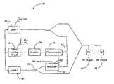
- FIG. 1illustrates a block diagram of a first embodiment of a photonic RF distribution system in accordance with the teachings of the invention
- FIG. 2illustrates the measured frequency response of the first embodiment of the RF distribution system
- FIG. 3illustrates the noise performance of a phase locked loop used in the first embodiment of the RF distribution system
- FIG. 4shows phase locking up to 50 GHz of the first embodiment of the RF distribution system
- FIG. 5illustrates the noise performance of the first embodiment of the RF distribution system for various frequencies
- FIG. 6illustrates a block diagram of a presently preferred embodiment of a photonic RF distribution system in accordance with the teachings of the invention
- FIG. 7illustrates the measured frequency response of the presently preferred embodiment of the RF distribution system
- FIG. 8shows phase locking up to 50 GHz of the presently preferred embodiment of the RF distribution system.
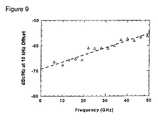
- FIG. 9illustrates the noise performance of the presently preferred embodiment of the RF distribution system for various frequencies.
- the photonic RF source 40is particularly suitable for RF photonic distribution.
- the photonic RF source 40includes a first laser 42 and a second laser 44 for generating optical signals that beat against one another to produce one or more RF output signals 45 .
- the lasers 42 and 44are preferably Nd:YAG lasers tuned to a wavelength of 1.319 um, lasing atfrequencies of v1 and v2 respectively.
- both of the lasers 42 and 44are tunable so that a wider tuning range is attainable.
- the scope of the inventionincludes tuning merely one of the lasers 42 and 44 to maintain the desired RF output signal. By tuning both lasers 42 and 44 , a tuning range of 50 GHz is attainable.
- a modulator 46is coupled to the second laser 44 through an optical coupler 48 . Also coupled to the modulator 46 is an input RF signal at ⁇ which is used to modulate a small portion of the optical signal from the second laser 44 .
- an intensity modulatorsuch as a Mach-Zehnder modulator is employed.
- the scope of the inventionincludes using other modulators that modulate other characteristics of the optical signal such as phase and frequency.
- the modulator 46acts as a photonic mixer that down converts the ⁇ tone using ⁇ as the local oscillator. As a result, the performance requirements on the RF components in the control loop are greatly reduced.
- the output of the modulator 46is coupled to a photodetector 50 .
- the photodetectoris also coupled through an optical coupler 52 to the first laser 42 .
- the combined optical signal from the modulator 46 and the first laser 42is sent to the photodetector 48 which is used to detect the beat frequency of the second laser 44 and the lower sideband of the first laser 42 .
- the photodetector 48emits a difference signal corresponding to the detected frequency.
- a low bandwidth photodetectoris employed to additionally attenuate the upper sidebands.
- a low noise amplifier 54amplifies the difference signal from the photodetector 50 and sends the amplified signal to an offset locking circuit 56 such as a phase locked loop, PLL.
- an offset locking circuit 56such as a phase locked loop, PLL.
- the difference signalis preferably amplified by the amplifier 54 , it is within the scope of the invention to directly couple the difference signal to the PLL 56 .
- the PLL 56controls the two lasers 42 and 44 by temperature tuning and by adjusting the cavity and pump power.
- the PLL 56is constructed in accordance with well known design principles to control the frequency difference between the lasers 42 and 44 .
- the scope of the inventionalso includes using other circuits for offset-frequency locking such as optical frequency locked loops (OFLL).
- OFLLoptical frequency locked loops
- the output of the lasers 42 and 44is combined and fed to multiple RF outputs 45 which are used for array applications.
- one of the optical signals from the lasers 42 and 44is coupled through the modulator 46 .
- the modulator 46modulates a small portion of the optical signal with an RF modulation frequency, ⁇ . Due to the input frequency range of the PLL, the modulation frequency, ⁇ , should satisfy the following equation:
- the modulated signalis then mixed at the photodetector 50 with a portion of the other optical signal.
- the generated sideband tonescontain a component at ⁇ - ⁇ .
- the sideband tonecan be at a lower frequency even when both ⁇ and ⁇ are very high.
- the modulator 46acts as a photonic mixer that down converts the ⁇ tone using ⁇ as the local oscillator. As a result, the performance requirements on the RF components in the control loop are greatly reduced.
- the phase information of the optical signalsis contained in the down converted signal, and can be used by the PLL 56 to generate the control feedback signal for the lasers 42 and 44 .
- the lasers 42 and 44are locked at a frequency difference of ⁇ , in which the offset ⁇ - ⁇ is controlled by the PLL 56 .
- the measured frequency response of the RF distribution system 40is shown in FIG. 2 .
- the frequency of the feedback signalwas chosen to be 500 MHz and is kept constant throughout the measurement.
- the RF power used to drive the modulator 46is also kept constant.
- the frequency response of the modulator 46 and the measuring PDis plotted for comparison to the phase locked frequency of the two lasers 42 and 44 .
- Optical power incident on the PDis preferably adjusted such that the power from each laser is equal to achieve a high modulation depth. Total optical power incident on the measuring PD is also kept constant. As the lasers 42 and 44 are tuned, mode hopping is observed and the optical power in the mode of interest changes causing the power in the RF tone to fluctuate with offset frequency.
- Another feature of the RF distribution system 40is not only the power of the phase locked tone, but also the noise performance of the system at higher frequencies. Shown in FIG. 3 is the noise performance of the PLL 56 without any external mixers or any external amplifiers. The frequency difference is 500 MHz and is directly fed into the PLL 56 . The PLL manufacturer specifies a noise performance of ⁇ 80 dBc/Hz at an offset of 10 kHz from the carrier. Noise peaks are also evident at 25 kHz offset from the carrier.
- FIG. 4shows phase locking up to 32 GHz with reasonable noise performance obtained with the distribution system 40 .
- the noise performance of the system 40 for various frequenciesis shown in FIG. 5 .
- the response of modulator 46decreases which will decrease the signal to noise ratio of the tone fed back into the PLL 56 .
- the signal in the feedback tonehas degraded so much that it becomes difficult to lock the two lasers 42 and 44 at any higher frequency.
- RF distribution system 140is configured in accordance with the principles of the invention.
- the RF distribution system 140is similar to RF distribution system 40 in function with corresponding elements numbered in the range 100-199, except that in RF distribution system 140 tapped portions of lasers 42 and 44 are first combined and then coupled to modulator 146 .
- the output of modulator 146is coupled to the photodetector 150 through a polarization controller 149 .
- This form of modulationwill generate sidebands of laser 2 142 and 144 .
- the feedback signalwill be generated by the beat frequency of the two nearest sidebands.
- the modulation frequency of the modulator 156should now satisfy the following equation: 1 ⁇ 2(
- a tuning range of 50 GHzis obtainable at a wavelength of 1.319 um.
- FIG. 7The measured frequency response of the RF distribution system 140 is shown in FIG. 7 .
- FIG. 8shows phase locking up to 50 GHz with reasonable noise performance obtained with the distribution system 140 .
- the noise performance of the system 140 for various frequenciesis shown in FIG. 9 .
- the RF distribution system 40 and 140effectively extend the frequency response of the modulator 46 from its ⁇ 3 dB point to a much broader band, such as the ⁇ 20 dB point. Since the PLL 56 uses only low frequency signals, less than 1 GHz for example, the loop sensitivity and dynamic range may both be increased by using various low frequency amplifiers and automatic gain control circuits. In addition, the low frequency PLL 56 may be used to compensate for loss in the modulator response.
- the phase locked photonic RF sources 40 and 140may be used to distribute RF power to multiple outputs such as in photonic controlled phased array antennas.
- the photonic RF generation/distribution systems 40 and 140use an electro-optical modulator (EO modulator) 46 as a photonic mixer to extend the bandwidth of tunability in a photonic RF source, thereby providing a broadband tuning range that exceeds the wideband 3 dB response of the modulator 46 .
- EO modulatorelectro-optical modulator
- the tuning range of the photonic RF sourcecan be extended to the limit of current EO modulator and photodetector packaging technology which is presently over 110 GHz.
- the high dynamic range in the down converted low frequency PLLwill require only a small portion of the optical power, leaving most of the optical power available for RF generation in multiple feeds.
Landscapes
- Engineering & Computer Science (AREA)
- Multimedia (AREA)
- Physics & Mathematics (AREA)
- Electromagnetism (AREA)
- Computer Networks & Wireless Communication (AREA)
- Signal Processing (AREA)
- Optical Modulation, Optical Deflection, Nonlinear Optics, Optical Demodulation, Optical Logic Elements (AREA)
Abstract
Description
|V1−V2>IF
where IF is the desired frequency of the feedback signal and should be less than operating range of the
½(|V1−V1|−IF)
Claims (25)
Priority Applications (1)
| Application Number | Priority Date | Filing Date | Title |
|---|---|---|---|
| US11/054,832US7379672B2 (en) | 2004-02-12 | 2005-02-10 | Photonic RF distribution system |
Applications Claiming Priority (2)
| Application Number | Priority Date | Filing Date | Title |
|---|---|---|---|
| US54404604P | 2004-02-12 | 2004-02-12 | |
| US11/054,832US7379672B2 (en) | 2004-02-12 | 2005-02-10 | Photonic RF distribution system |
Publications (2)
| Publication Number | Publication Date |
|---|---|
| US20050201759A1 US20050201759A1 (en) | 2005-09-15 |
| US7379672B2true US7379672B2 (en) | 2008-05-27 |
Family
ID=34885999
Family Applications (1)
| Application Number | Title | Priority Date | Filing Date |
|---|---|---|---|
| US11/054,832Active2026-08-07US7379672B2 (en) | 2004-02-12 | 2005-02-10 | Photonic RF distribution system |
Country Status (3)
| Country | Link |
|---|---|
| US (1) | US7379672B2 (en) |
| EP (1) | EP1714409A1 (en) |
| WO (1) | WO2005081431A1 (en) |
Cited By (6)
| Publication number | Priority date | Publication date | Assignee | Title |
|---|---|---|---|---|
| US20080075464A1 (en)* | 2006-09-05 | 2008-03-27 | Oewaves, Inc. | Wideband receiver based on photonics technology |
| US20130064542A1 (en)* | 2011-09-12 | 2013-03-14 | Adva Optical Networking Se | Optical frequency locking method and device for optical data transmission |
| US8761603B1 (en)* | 2009-02-25 | 2014-06-24 | Oewaves, Inc. | Dynamically reconfigurable sensor arrays |
| US20180138980A1 (en)* | 2016-11-15 | 2018-05-17 | Huawei Technologies Co., Ltd. | Optical transceiver, communication system, and adaptive frequency control method |
| US10447387B2 (en)* | 2013-03-15 | 2019-10-15 | Nec Corporation | Optical transmission/ reception device, optical communication system and optical transmission/ reception method |
| US10917172B2 (en)* | 2017-07-14 | 2021-02-09 | Nec Corporation | Pluggable optical module, optical communication system, and control method of pluggable optical module |
Families Citing this family (6)
| Publication number | Priority date | Publication date | Assignee | Title |
|---|---|---|---|---|
| US7499603B1 (en) | 2006-01-19 | 2009-03-03 | Lockheed Martin Corporation | Range extended electrooptic modulator |
| US7773116B1 (en) | 2006-02-08 | 2010-08-10 | Lockheed Martin Corporation | Digital imaging stabilization |
| US8249460B2 (en)* | 2007-06-22 | 2012-08-21 | Lockheed Martin Corporation | Apparatus and method for generating an RF signal |
| WO2018044500A1 (en)* | 2016-09-01 | 2018-03-08 | Imra America, Inc. | Ultra low noise photonic phase noise measurement system for microwave signal |
| US12247835B2 (en)* | 2021-03-22 | 2025-03-11 | Nexus Photonics Inc | Stabilized frequency generator |
| US20230032715A1 (en)* | 2021-07-27 | 2023-02-02 | Oewaves, Inc. | One-way optical link for precision frequency transfer between stationary or moving platforms |
Citations (5)
| Publication number | Priority date | Publication date | Assignee | Title |
|---|---|---|---|---|
| US5396361A (en) | 1988-07-29 | 1995-03-07 | Hitachi, Ltd. | Frequency separation stabilization method for optical heterodyne or optical homodyne communication |
| DE19625817A1 (en) | 1996-06-28 | 1998-01-02 | Sel Alcatel Ag | Optical transmitter for a hybrid fiber-radio system |
| US20030112836A1 (en) | 2001-12-18 | 2003-06-19 | Kim Bong Kyu | Multiwavelength locking method and apparatus using acousto-optic tunable filter |
| US6766070B2 (en)* | 2001-04-27 | 2004-07-20 | The United States Of America As Represented By The Secretary Of The Navy | High power fiber optic modulator system and method |
| US6807203B2 (en)* | 2001-12-05 | 2004-10-19 | Lightwave Electronics Corporation | Calibrating a frequency difference between two or more lasers over an extended frequency range |
Family Cites Families (46)
| Publication number | Priority date | Publication date | Assignee | Title |
|---|---|---|---|---|
| US5431666A (en)* | 1994-02-24 | 1995-07-11 | Lasersurge, Inc. | Surgical suture instrument |
| US5395361A (en)* | 1994-06-16 | 1995-03-07 | Pillco Limited Partnership | Expandable fiberoptic catheter and method of intraluminal laser transmission |
| US5582616A (en)* | 1994-08-05 | 1996-12-10 | Origin Medsystems, Inc. | Surgical helical fastener with applicator |
| US5645568A (en)* | 1995-11-20 | 1997-07-08 | Medicinelodge, Inc. | Expandable body suture |
| US6001110A (en)* | 1997-06-20 | 1999-12-14 | Boston Scientific Corporation | Hemostatic clips |
| US5997556A (en)* | 1997-06-30 | 1999-12-07 | Eva Corporation | Surgical fastener |
| US6086600A (en)* | 1997-11-03 | 2000-07-11 | Symbiosis Corporation | Flexible endoscopic surgical instrument for invagination and fundoplication |
| US6551328B2 (en)* | 1997-11-03 | 2003-04-22 | Symbiosis Corporation | Surgical instrument for invagination and fundoplication |
| CA2358387C (en)* | 1998-12-31 | 2007-11-13 | Jeffrey E. Yeung | Tissue fastening devices and delivery means |
| WO2000059376A1 (en)* | 1999-04-07 | 2000-10-12 | Endonetics, Inc. | Implantable monitoring probe |
| US6338345B1 (en)* | 1999-04-07 | 2002-01-15 | Endonetics, Inc. | Submucosal prosthesis delivery device |
| US6285897B1 (en)* | 1999-04-07 | 2001-09-04 | Endonetics, Inc. | Remote physiological monitoring system |
| US6835200B2 (en)* | 1999-06-22 | 2004-12-28 | Ndo Surgical. Inc. | Method and devices for tissue reconfiguration |
| US6821285B2 (en)* | 1999-06-22 | 2004-11-23 | Ndo Surgical, Inc. | Tissue reconfiguration |
| US7416554B2 (en)* | 2002-12-11 | 2008-08-26 | Usgi Medical Inc | Apparatus and methods for forming and securing gastrointestinal tissue folds |
| US6626899B2 (en)* | 1999-06-25 | 2003-09-30 | Nidus Medical, Llc | Apparatus and methods for treating tissue |
| US7618426B2 (en)* | 2002-12-11 | 2009-11-17 | Usgi Medical, Inc. | Apparatus and methods for forming gastrointestinal tissue approximations |
| US7744613B2 (en)* | 1999-06-25 | 2010-06-29 | Usgi Medical, Inc. | Apparatus and methods for forming and securing gastrointestinal tissue folds |
| US7637905B2 (en)* | 2003-01-15 | 2009-12-29 | Usgi Medical, Inc. | Endoluminal tool deployment system |
| EP1253860A4 (en)* | 2000-02-09 | 2006-04-26 | Eva Corp | Surgical fastener |
| EP1261282B1 (en)* | 2000-03-03 | 2013-09-25 | C. R. Bard, Inc. | Endoscopic tissue apposition device with multiple suction ports |
| JP4477280B2 (en)* | 2000-03-16 | 2010-06-09 | メディガス リミテッド | Gastric fistula wall forming device |
| WO2003030983A1 (en)* | 2001-04-06 | 2003-04-17 | Sumitomo Bakelite Co., Ltd. | Esophagus stoma button |
| US6592596B1 (en)* | 2000-05-10 | 2003-07-15 | Scimed Life Systems, Inc. | Devices and related methods for securing a tissue fold |
| US6921361B2 (en)* | 2000-07-24 | 2005-07-26 | Olympus Corporation | Endoscopic instrument for forming an artificial valve |
| US6535764B2 (en)* | 2001-05-01 | 2003-03-18 | Intrapace, Inc. | Gastric treatment and diagnosis device and method |
| US6916332B2 (en)* | 2001-05-23 | 2005-07-12 | Scimed Life Systems, Inc. | Endoluminal fundoplication device and related method for installing tissue fastener |
| US6692507B2 (en)* | 2001-08-23 | 2004-02-17 | Scimed Life Systems, Inc. | Impermanent biocompatible fastener |
| US7104949B2 (en)* | 2001-08-31 | 2006-09-12 | Ams Research Corporation | Surgical articles for placing an implant about a tubular tissue structure and methods |
| US6740121B2 (en)* | 2001-11-09 | 2004-05-25 | Boston Scientific Corporation | Intragastric stent for duodenum bypass |
| US8142448B2 (en)* | 2001-11-26 | 2012-03-27 | Olympus Corporation | Endoscopic instruments for suturing tissues in a body cavity |
| JP2005524485A (en)* | 2002-05-09 | 2005-08-18 | ディー.イーガン トマス | Gastric bypass prosthesis |
| US6972027B2 (en)* | 2002-06-26 | 2005-12-06 | Stryker Endoscopy | Soft tissue repair system |
| US7033378B2 (en)* | 2002-09-20 | 2006-04-25 | Id, Llc | Surgical fastener, particularly for the endoluminal treatment of gastroesophageal reflux disease (GERD) |
| US6966919B2 (en)* | 2002-09-20 | 2005-11-22 | Id, Llc | Instrument for applying a surgical fastener particularly for the transoral treatment of gastroesophageal reflux disease (GERD) |
| US7229428B2 (en)* | 2002-10-23 | 2007-06-12 | Satiety, Inc. | Method and device for use in endoscopic organ procedures |
| US7837669B2 (en)* | 2002-11-01 | 2010-11-23 | Valentx, Inc. | Devices and methods for endolumenal gastrointestinal bypass |
| US8070743B2 (en)* | 2002-11-01 | 2011-12-06 | Valentx, Inc. | Devices and methods for attaching an endolumenal gastrointestinal implant |
| US7794447B2 (en)* | 2002-11-01 | 2010-09-14 | Valentx, Inc. | Gastrointestinal sleeve device and methods for treatment of morbid obesity |
| US20090149871A9 (en)* | 2002-11-01 | 2009-06-11 | Jonathan Kagan | Devices and methods for treating morbid obesity |
| US9060844B2 (en)* | 2002-11-01 | 2015-06-23 | Valentx, Inc. | Apparatus and methods for treatment of morbid obesity |
| CA2507803C (en)* | 2002-11-29 | 2012-12-04 | John R. Liddicoat | Apparatus and method for manipulating tissue |
| US7025791B2 (en)* | 2002-12-02 | 2006-04-11 | Gi Dynamics, Inc. | Bariatric sleeve |
| US20040249367A1 (en)* | 2003-01-15 | 2004-12-09 | Usgi Medical Corp. | Endoluminal tool deployment system |
| US20040181242A1 (en)* | 2003-03-12 | 2004-09-16 | Stack Richard S. | Articulated suturing system |
| KR20060009388A (en)* | 2003-06-09 | 2006-01-31 | 코닝 인코포레이티드 | Optical communication system with suppressed SVs |
- 2005
- 2005-02-10WOPCT/US2005/004019patent/WO2005081431A1/ennot_activeApplication Discontinuation
- 2005-02-10EPEP05722838Apatent/EP1714409A1/ennot_activeWithdrawn
- 2005-02-10USUS11/054,832patent/US7379672B2/enactiveActive
Patent Citations (5)
| Publication number | Priority date | Publication date | Assignee | Title |
|---|---|---|---|---|
| US5396361A (en) | 1988-07-29 | 1995-03-07 | Hitachi, Ltd. | Frequency separation stabilization method for optical heterodyne or optical homodyne communication |
| DE19625817A1 (en) | 1996-06-28 | 1998-01-02 | Sel Alcatel Ag | Optical transmitter for a hybrid fiber-radio system |
| US6766070B2 (en)* | 2001-04-27 | 2004-07-20 | The United States Of America As Represented By The Secretary Of The Navy | High power fiber optic modulator system and method |
| US6807203B2 (en)* | 2001-12-05 | 2004-10-19 | Lightwave Electronics Corporation | Calibrating a frequency difference between two or more lasers over an extended frequency range |
| US20030112836A1 (en) | 2001-12-18 | 2003-06-19 | Kim Bong Kyu | Multiwavelength locking method and apparatus using acousto-optic tunable filter |
Non-Patent Citations (2)
| Title |
|---|
| B. Jensen and L.G. Kozovsky; Relative Frequency Stabilization of a Set of Lasers Using Optical Phase-Locked Loops; pp. 535-538; TFL Telecommunications Research Laboratory; Horsholm, Denmark. |
| Jensen, B. et al., "Relative Frequency Stabilization of a set of Lasers Using Optical Phase-Locked Loops," Proceedings of the European Conference on Optical Communication, Sep. 1990, pp. 535-538, vol. 1, Amsterdam, Denmark. |
Cited By (16)
| Publication number | Priority date | Publication date | Assignee | Title |
|---|---|---|---|---|
| US20080075464A1 (en)* | 2006-09-05 | 2008-03-27 | Oewaves, Inc. | Wideband receiver based on photonics technology |
| WO2008030782A3 (en)* | 2006-09-05 | 2009-04-09 | Oewaves Inc | Wideband receiver based on photonics technology |
| US7634201B2 (en)* | 2006-09-05 | 2009-12-15 | Oewaves, Inc. | Wideband receiver based on photonics technology |
| US8761603B1 (en)* | 2009-02-25 | 2014-06-24 | Oewaves, Inc. | Dynamically reconfigurable sensor arrays |
| US20130064542A1 (en)* | 2011-09-12 | 2013-03-14 | Adva Optical Networking Se | Optical frequency locking method and device for optical data transmission |
| US9166695B2 (en)* | 2011-09-12 | 2015-10-20 | Adva Optical Networking Se | Optical frequency locking method and device for optical data transmission |
| US10447387B2 (en)* | 2013-03-15 | 2019-10-15 | Nec Corporation | Optical transmission/ reception device, optical communication system and optical transmission/ reception method |
| US20200091999A1 (en)* | 2013-03-15 | 2020-03-19 | Nec Corporation | Optical transmission/ reception device, optical communication system and optical transmission/ reception method |
| US10880003B2 (en)* | 2013-03-15 | 2020-12-29 | Nec Corporation | Optical transmission/ reception device, optical communication system and optical transmission/ reception method |
| US11277202B2 (en) | 2013-03-15 | 2022-03-15 | Nec Corporation | Optical transmission/reception device, optical communications system and optical transmission/reception method |
| US20220158726A1 (en)* | 2013-03-15 | 2022-05-19 | Nec Corporation | Optical transmission/reception device, optical communications system and optical transmission/reception method |
| US12255681B2 (en)* | 2013-03-15 | 2025-03-18 | Nec Corporation | Optical transmission/reception device, optical communications system and optical transmission/reception method |
| US10187155B2 (en)* | 2016-11-15 | 2019-01-22 | Huawei Technologies Co., Ltd. | Optical transceiver, communication system, and adaptive frequency control method |
| US20180138980A1 (en)* | 2016-11-15 | 2018-05-17 | Huawei Technologies Co., Ltd. | Optical transceiver, communication system, and adaptive frequency control method |
| US10917172B2 (en)* | 2017-07-14 | 2021-02-09 | Nec Corporation | Pluggable optical module, optical communication system, and control method of pluggable optical module |
| US11342991B2 (en)* | 2017-07-14 | 2022-05-24 | Nec Corporation | Pluggable optical module, optical communication system, and control method of pluggable optical module |
Also Published As
| Publication number | Publication date |
|---|---|
| EP1714409A1 (en) | 2006-10-25 |
| US20050201759A1 (en) | 2005-09-15 |
| WO2005081431A1 (en) | 2005-09-01 |
Similar Documents
| Publication | Publication Date | Title |
|---|---|---|
| US7133615B2 (en) | Two-optical signal generator for generating two optical signals having adjustable optical frequency difference | |
| US20040208643A1 (en) | Coherent optical receivers | |
| US6417957B1 (en) | Opto-electronic devices for processing and transmitting RF signals based on brillouin selective sideband amplification | |
| US5777778A (en) | Multi-Loop opto-electronic microwave oscillator with a wide tuning range | |
| US5917179A (en) | Brillouin opto-electronic oscillators | |
| US20050018724A1 (en) | Optical frequency synthesizer | |
| CN111092659B (en) | A Double-chirp Signal Generation System Based on Stimulated Brillouin Scattering | |
| US20100092183A1 (en) | Frequency tunable terahertz continuous wave generator | |
| US7330665B2 (en) | Optical frequency modulated transmitter | |
| US7379672B2 (en) | Photonic RF distribution system | |
| CN111541150B (en) | Device and method for realizing wavelength dynamic locking of semiconductor laser | |
| US5544183A (en) | Variable wavelength light source | |
| WO2002082693A1 (en) | Optical linearizer for fiber communications | |
| JP2008288390A (en) | Tunable optical frequency stabilized light source | |
| CN114865445A (en) | Frequency-tunable ultra-stable laser generation method and laser system based on modulation sideband frequency locking | |
| EP2036225A1 (en) | Optical frequency comb generator | |
| US20210226418A1 (en) | Multi-wavelength laser | |
| GB2250394A (en) | Optical frequency synthesis | |
| JPH0139668B2 (en) | ||
| Sun et al. | Frequency synthesis of forced opto-electronic oscillators at the X-band | |
| Kassem et al. | Photonic Synthesis of Continuously Tunable (5–170 GHz) Microwave Signals with Frequency Independent Phase Noise | |
| JP4458769B2 (en) | 2 optical signal generator | |
| JP3891361B2 (en) | Frequency synthesizer | |
| Peng et al. | Photonic RF synthesizer based on a phase-locked optoelectronic oscillator using anti-Stokes loss spectrum of stimulated Brillouin scattering | |
| KR100211583B1 (en) | The stabilizing system of laser diode for wavelength division multiplexing |
Legal Events
| Date | Code | Title | Description |
|---|---|---|---|
| AS | Assignment | Owner name:NORTHROP GRUMMAN CORPORATION, CALIFORNIA Free format text:ASSIGNMENT OF ASSIGNORS INTEREST;ASSIGNORS:WANG, WENSHEN;SCOTT, DAVID C.;JUNG, THOMAS JING-MING;AND OTHERS;REEL/FRAME:016271/0356;SIGNING DATES FROM 20050203 TO 20050209 | |
| FEPP | Fee payment procedure | Free format text:PAYOR NUMBER ASSIGNED (ORIGINAL EVENT CODE: ASPN); ENTITY STATUS OF PATENT OWNER: LARGE ENTITY | |
| STCF | Information on status: patent grant | Free format text:PATENTED CASE | |
| AS | Assignment | Owner name:NORTHROP GRUMMAN SPACE & MISSION SYSTEMS CORP.,CAL Free format text:ASSIGNMENT OF ASSIGNORS INTEREST;ASSIGNOR:NORTHROP GRUMMAN CORPORTION;REEL/FRAME:023699/0551 Effective date:20091125 Owner name:NORTHROP GRUMMAN SPACE & MISSION SYSTEMS CORP., CA Free format text:ASSIGNMENT OF ASSIGNORS INTEREST;ASSIGNOR:NORTHROP GRUMMAN CORPORTION;REEL/FRAME:023699/0551 Effective date:20091125 | |
| AS | Assignment | Owner name:NORTHROP GRUMMAN SYSTEMS CORPORATION,CALIFORNIA Free format text:ASSIGNMENT OF ASSIGNORS INTEREST;ASSIGNOR:NORTHROP GRUMMAN SPACE & MISSION SYSTEMS CORP.;REEL/FRAME:023915/0446 Effective date:20091210 Owner name:NORTHROP GRUMMAN SYSTEMS CORPORATION, CALIFORNIA Free format text:ASSIGNMENT OF ASSIGNORS INTEREST;ASSIGNOR:NORTHROP GRUMMAN SPACE & MISSION SYSTEMS CORP.;REEL/FRAME:023915/0446 Effective date:20091210 | |
| FPAY | Fee payment | Year of fee payment:4 | |
| FPAY | Fee payment | Year of fee payment:8 | |
| MAFP | Maintenance fee payment | Free format text:PAYMENT OF MAINTENANCE FEE, 12TH YEAR, LARGE ENTITY (ORIGINAL EVENT CODE: M1553); ENTITY STATUS OF PATENT OWNER: LARGE ENTITY Year of fee payment:12 |