US7377904B2 - Cap displacement mechanism for lancing device and multi-lancet cartridge - Google Patents
Cap displacement mechanism for lancing device and multi-lancet cartridgeDownload PDFInfo
- Publication number
- US7377904B2 US7377904B2US11/107,984US10798405AUS7377904B2US 7377904 B2US7377904 B2US 7377904B2US 10798405 AUS10798405 AUS 10798405AUS 7377904 B2US7377904 B2US 7377904B2
- Authority
- US
- United States
- Prior art keywords
- active
- lancet
- cap
- lancing
- lancets
- Prior art date
- Legal status (The legal status is an assumption and is not a legal conclusion. Google has not performed a legal analysis and makes no representation as to the accuracy of the status listed.)
- Expired - Lifetime, expires
Links
Images


Classifications
- A—HUMAN NECESSITIES
- A61—MEDICAL OR VETERINARY SCIENCE; HYGIENE
- A61B—DIAGNOSIS; SURGERY; IDENTIFICATION
- A61B5/00—Measuring for diagnostic purposes; Identification of persons
- A61B5/15—Devices for taking samples of blood
- A61B5/151—Devices specially adapted for taking samples of capillary blood, e.g. by lancets, needles or blades
- A61B5/15146—Devices loaded with multiple lancets simultaneously, e.g. for serial firing without reloading, for example by use of stocking means.
- A—HUMAN NECESSITIES
- A61—MEDICAL OR VETERINARY SCIENCE; HYGIENE
- A61B—DIAGNOSIS; SURGERY; IDENTIFICATION
- A61B5/00—Measuring for diagnostic purposes; Identification of persons
- A61B5/15—Devices for taking samples of blood
- A61B5/150007—Details
- A61B5/150015—Source of blood
- A61B5/150022—Source of blood for capillary blood or interstitial fluid
- A—HUMAN NECESSITIES
- A61—MEDICAL OR VETERINARY SCIENCE; HYGIENE
- A61B—DIAGNOSIS; SURGERY; IDENTIFICATION
- A61B5/00—Measuring for diagnostic purposes; Identification of persons
- A61B5/15—Devices for taking samples of blood
- A61B5/150007—Details
- A61B5/150175—Adjustment of penetration depth
- A61B5/150183—Depth adjustment mechanism using end caps mounted at the distal end of the sampling device, i.e. the end-caps are adjustably positioned relative to the piercing device housing for example by rotating or screwing
- A—HUMAN NECESSITIES
- A61—MEDICAL OR VETERINARY SCIENCE; HYGIENE
- A61B—DIAGNOSIS; SURGERY; IDENTIFICATION
- A61B5/00—Measuring for diagnostic purposes; Identification of persons
- A61B5/15—Devices for taking samples of blood
- A61B5/150007—Details
- A61B5/150374—Details of piercing elements or protective means for preventing accidental injuries by such piercing elements
- A61B5/150381—Design of piercing elements
- A61B5/150412—Pointed piercing elements, e.g. needles, lancets for piercing the skin
- A—HUMAN NECESSITIES
- A61—MEDICAL OR VETERINARY SCIENCE; HYGIENE
- A61B—DIAGNOSIS; SURGERY; IDENTIFICATION
- A61B5/00—Measuring for diagnostic purposes; Identification of persons
- A61B5/15—Devices for taking samples of blood
- A61B5/150007—Details
- A61B5/150374—Details of piercing elements or protective means for preventing accidental injuries by such piercing elements
- A61B5/150381—Design of piercing elements
- A61B5/150503—Single-ended needles
- A61B5/150519—Details of construction of hub, i.e. element used to attach the single-ended needle to a piercing device or sampling device
- A—HUMAN NECESSITIES
- A61—MEDICAL OR VETERINARY SCIENCE; HYGIENE
- A61B—DIAGNOSIS; SURGERY; IDENTIFICATION
- A61B5/00—Measuring for diagnostic purposes; Identification of persons
- A61B5/15—Devices for taking samples of blood
- A61B5/150007—Details
- A61B5/150374—Details of piercing elements or protective means for preventing accidental injuries by such piercing elements
- A61B5/150534—Design of protective means for piercing elements for preventing accidental needle sticks, e.g. shields, caps, protectors, axially extensible sleeves, pivotable protective sleeves
- A61B5/150541—Breakable protectors, e.g. caps, shields or sleeves, i.e. protectors separated destructively, e.g. by breaking a connecting area
- A61B5/150564—Protectors removed by pulling or pushing
- A—HUMAN NECESSITIES
- A61—MEDICAL OR VETERINARY SCIENCE; HYGIENE
- A61B—DIAGNOSIS; SURGERY; IDENTIFICATION
- A61B5/00—Measuring for diagnostic purposes; Identification of persons
- A61B5/15—Devices for taking samples of blood
- A61B5/150007—Details
- A61B5/150374—Details of piercing elements or protective means for preventing accidental injuries by such piercing elements
- A61B5/150534—Design of protective means for piercing elements for preventing accidental needle sticks, e.g. shields, caps, protectors, axially extensible sleeves, pivotable protective sleeves
- A61B5/15058—Joining techniques used for protective means
- A61B5/150618—Integrally moulded protectors, e.g. protectors simultaneously moulded together with a further component, e.g. a hub, of the piercing element
- A—HUMAN NECESSITIES
- A61—MEDICAL OR VETERINARY SCIENCE; HYGIENE
- A61B—DIAGNOSIS; SURGERY; IDENTIFICATION
- A61B5/00—Measuring for diagnostic purposes; Identification of persons
- A61B5/15—Devices for taking samples of blood
- A61B5/150007—Details
- A61B5/150374—Details of piercing elements or protective means for preventing accidental injuries by such piercing elements
- A61B5/150534—Design of protective means for piercing elements for preventing accidental needle sticks, e.g. shields, caps, protectors, axially extensible sleeves, pivotable protective sleeves
- A61B5/150694—Procedure for removing protection means at the time of piercing
- A61B5/150725—Procedure for removing protection means at the time of piercing removal procedure linked to further actions, e.g. cocking of the piercing device, which indicate that the piercing device is used or tempered
- A—HUMAN NECESSITIES
- A61—MEDICAL OR VETERINARY SCIENCE; HYGIENE
- A61B—DIAGNOSIS; SURGERY; IDENTIFICATION
- A61B5/00—Measuring for diagnostic purposes; Identification of persons
- A61B5/15—Devices for taking samples of blood
- A61B5/150007—Details
- A61B5/150885—Preventing re-use
- A—HUMAN NECESSITIES
- A61—MEDICAL OR VETERINARY SCIENCE; HYGIENE
- A61B—DIAGNOSIS; SURGERY; IDENTIFICATION
- A61B5/00—Measuring for diagnostic purposes; Identification of persons
- A61B5/15—Devices for taking samples of blood
- A61B5/151—Devices specially adapted for taking samples of capillary blood, e.g. by lancets, needles or blades
- A61B5/15101—Details
- A61B5/15103—Piercing procedure
- A61B5/15107—Piercing being assisted by a triggering mechanism
- A61B5/15113—Manually triggered, i.e. the triggering requires a deliberate action by the user such as pressing a drive button
- A—HUMAN NECESSITIES
- A61—MEDICAL OR VETERINARY SCIENCE; HYGIENE
- A61B—DIAGNOSIS; SURGERY; IDENTIFICATION
- A61B5/00—Measuring for diagnostic purposes; Identification of persons
- A61B5/15—Devices for taking samples of blood
- A61B5/151—Devices specially adapted for taking samples of capillary blood, e.g. by lancets, needles or blades
- A61B5/15101—Details
- A61B5/15115—Driving means for propelling the piercing element to pierce the skin, e.g. comprising mechanisms based on shape memory alloys, magnetism, solenoids, piezoelectric effect, biased elements, resilient elements, vacuum or compressed fluids
- A61B5/15117—Driving means for propelling the piercing element to pierce the skin, e.g. comprising mechanisms based on shape memory alloys, magnetism, solenoids, piezoelectric effect, biased elements, resilient elements, vacuum or compressed fluids comprising biased elements, resilient elements or a spring, e.g. a helical spring, leaf spring, or elastic strap
- A—HUMAN NECESSITIES
- A61—MEDICAL OR VETERINARY SCIENCE; HYGIENE
- A61B—DIAGNOSIS; SURGERY; IDENTIFICATION
- A61B5/00—Measuring for diagnostic purposes; Identification of persons
- A61B5/15—Devices for taking samples of blood
- A61B5/151—Devices specially adapted for taking samples of capillary blood, e.g. by lancets, needles or blades
- A61B5/15146—Devices loaded with multiple lancets simultaneously, e.g. for serial firing without reloading, for example by use of stocking means.
- A61B5/15148—Constructional features of stocking means, e.g. strip, roll, disc, cartridge, belt or tube
- A61B5/15149—Arrangement of piercing elements relative to each other
- A61B5/15153—Multiple piercing elements stocked in a single compartment
- A—HUMAN NECESSITIES
- A61—MEDICAL OR VETERINARY SCIENCE; HYGIENE
- A61B—DIAGNOSIS; SURGERY; IDENTIFICATION
- A61B5/00—Measuring for diagnostic purposes; Identification of persons
- A61B5/15—Devices for taking samples of blood
- A61B5/151—Devices specially adapted for taking samples of capillary blood, e.g. by lancets, needles or blades
- A61B5/15146—Devices loaded with multiple lancets simultaneously, e.g. for serial firing without reloading, for example by use of stocking means.
- A61B5/15148—Constructional features of stocking means, e.g. strip, roll, disc, cartridge, belt or tube
- A61B5/15157—Geometry of stocking means or arrangement of piercing elements therein
- A61B5/15159—Piercing elements stocked in or on a disc
- A61B5/15161—Characterized by propelling the piercing element in a radial direction relative to the disc
- A—HUMAN NECESSITIES
- A61—MEDICAL OR VETERINARY SCIENCE; HYGIENE
- A61B—DIAGNOSIS; SURGERY; IDENTIFICATION
- A61B5/00—Measuring for diagnostic purposes; Identification of persons
- A61B5/15—Devices for taking samples of blood
- A61B5/151—Devices specially adapted for taking samples of capillary blood, e.g. by lancets, needles or blades
- A61B5/15146—Devices loaded with multiple lancets simultaneously, e.g. for serial firing without reloading, for example by use of stocking means.
- A61B5/15148—Constructional features of stocking means, e.g. strip, roll, disc, cartridge, belt or tube
- A61B5/15176—Stocking means comprising cap, cover, sheath or protection for aseptic stocking
- A—HUMAN NECESSITIES
- A61—MEDICAL OR VETERINARY SCIENCE; HYGIENE
- A61B—DIAGNOSIS; SURGERY; IDENTIFICATION
- A61B5/00—Measuring for diagnostic purposes; Identification of persons
- A61B5/15—Devices for taking samples of blood
- A61B5/151—Devices specially adapted for taking samples of capillary blood, e.g. by lancets, needles or blades
- A61B5/15146—Devices loaded with multiple lancets simultaneously, e.g. for serial firing without reloading, for example by use of stocking means.
- A61B5/15182—Means for keeping track or checking of the total number of piercing elements already used or the number of piercing elements still remaining in the stocking, e.g. by check window, counter, display
- A—HUMAN NECESSITIES
- A61—MEDICAL OR VETERINARY SCIENCE; HYGIENE
- A61B—DIAGNOSIS; SURGERY; IDENTIFICATION
- A61B17/00—Surgical instruments, devices or methods
- A61B17/32—Surgical cutting instruments
- A61B17/3205—Excision instruments
- A61B17/32053—Punch like cutting instruments, e.g. using a cylindrical or oval knife
- A—HUMAN NECESSITIES
- A61—MEDICAL OR VETERINARY SCIENCE; HYGIENE
- A61B—DIAGNOSIS; SURGERY; IDENTIFICATION
- A61B17/00—Surgical instruments, devices or methods
- A61B17/32—Surgical cutting instruments
- A61B17/3209—Incision instruments
- A61B17/32093—Incision instruments for skin incisions
Definitions
- the present inventionrelates generally to medical devices and procedures and, more particularly to cartridge assemblies for lancing devices for the collection and/or analysis of samples of blood or other bodily fluids.
- a sharp lancet tipis commonly used to puncture the subject's skin at a lancing site to obtain a sample of blood, interstitial fluid, or other body fluid, as for example in blood glucose monitoring by diabetics and in blood typing and screening applications.
- a personmust periodically sample their blood for multiple testing throughout the day or week. Because re-use of a lancet can result in infection or spread of blood-borne contaminants, persons requiring repeated testing often must carry around multiple lancets that are separately loaded into a lancing device for each sampling. This can be inconvenient and may lead to reduced compliance with a prescribed test regimen.
- the present inventionis a lancing device comprising an outer housing for receiving a replaceable cartridge.
- the cartridgeincludes a static outer shell that remains stationary relative to the housing and drive mechanism of the lancing device, and an array of lancets that are rotationally advanced within the outer shell and sequentially indexed through an active position for carrying out multiple lancing procedures.
- the cartridgepreferably includes a rotationally moveable carrier for retaining and rotationally advancing the radial array of lancets within the outer shell, and for constraining the active lancet along a controlled and pre-defined path of travel during the lancing stroke.
- the cartridgepreferably also includes recesses, clips or other retainers for retaining protective endcaps that have been removed from the lancets out of the path of travel of the lancets, and preventing the caps from rattling around within the housing.
- the lancing devicepreferably includes a drive mechanism, including for example a pair of opposed biasing mechanisms (e.g., springs) working in tandem, to drive and return the plunger mechanism of the lancing device and propel the active lancet through its lancing stroke.
- the jaw of the drive mechanismengages the active lancet from the bottom only, through a slot in the cartridge shell, so that a partially spent cartridge can be removed from the lancing device and reinserted for use at a later time.
- the lancing deviceincludes a one-way clutch or ratchet mechanism to advance lancets sequentially through the active position and to prevent re-use of lancets.
- the lancing devicepreferably also includes an advancing and charging mechanism for sequentially indexing the lancet carrier, charging the drive mechanism, and detaching the endcap of the lancet at a controlled retraction rate during de-capping, all with a single and continuous operation.
- the lancing deviceoptionally includes a depth ring for adjusting the depth of penetration of the lancet.
- the depth ringhas a plurality of openings with varying opening sizes and varying countersink depths, and is rotatable through a sequence of positions adjacent the lancet opening in the housing of the lancing device, thereby forming a rotating shutter window, providing a wide range of depth control.
- the lancing deviceincludes an improved activating button operable to activate the drive mechanism, and including an integral spring arm for biasing the activating button outwardly and a retainer for securing the rotating depth ring.
- the inventionis an improved cartridge assembly for use with a multi-use lancing device.
- the cartridge assemblypreferably includes a plurality of penetration elements or lancets, each having its own protective covering or endcap, arranged for sequential use in piercing the skin or other tissue of a human or animal subject for obtaining a sample of blood, interstitial fluid, and/or other body fluid(s).
- the cartridgehas an outer shell or housing and a carrier assembly rotationally enclosed within the outer shell for retaining the lancets. Because the carrier rotationally advances the lancets within the outer shell of the cartridge, only one opening through the shell is required for allowing passage of the active lancet tip upon actuation of the device, thereby reducing the potential for contamination or accidental needle sticks.
- the present inventionis a cap displacement mechanism that moves a sterility cap, after it has been separated from the active lancet out of the lancing stroke travel path of the active lancet.
- the cartridgeincludes a cantilevered spring arm that is mounted within the cartridge shell to bias the separated lancet cap out of the path of the lancing stroke.
- the lancing deviceincludes a spring-biased plunger that is driven along a cam surface of the lancing device to engage a lancet cap and push it transversely out of the path of the lancing stroke.
- the carrierpreferably defines transverse guide paths near its outer perimeter for directing and retaining the lancet caps out of the travel path of the lancet tip.
- transverse guide pathsare preferably defined by one or more guide tracks (e.g., resilient fingers, barbs, or other engagement features) extending from the carrier for positively retaining the lancet caps that have been removed from the lancet bodies.
- guide trackse.g., resilient fingers, barbs, or other engagement features
- transverse cap displacementmeans displacement of the cap out of the lancing stroke path, for example, up, down, or laterally to one side or the other.
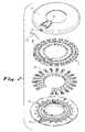
- FIG. 1is a perspective view of a multi-lancet cartridge assembly for a lancing device in accordance with a first example embodiment of the present invention.
- FIG. 2is an exploded perspective view of the cartridge assembly of FIG. 1 , showing a base housing, lancet array, carrier disk, spring-arm cap displacer, and cover housing.
- FIG. 3is a cutaway perspective view of the lancet array, carrier, and spring arm of FIG. 2 , showing spring arm displacing a separated cap of an active lancet.
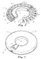
- FIG. 4is a perspective view of a cartridge assembly for a lancing device in accordance with a second example embodiment of the present invention.
- FIG. 5is an exploded perspective view of the cartridge assembly of FIG. 4 , showing a base housing, lancet array, carrier disk, and cover housing.
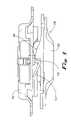
- FIG. 6is a partial perspective view of an advancer mechanism of the lancing device for use with the cartridge of FIG. 4 , showing a spring-loaded cap-displacing plunger driven by a cam surface of the advancer mechanism.
- FIG. 7is a perspective view of a lancing device according to the second example embodiment of the invention, suited for use with the cartridge assembly of FIG. 4 , showing the lancing device in an opened position revealing the advancer mechanism of FIG. 6 situated therein, and showing the spring-loaded cam-driven plunger extending through the upper shell of the advancer mechanism.
- FIG. 8is a partial cutaway perspective view of the advancer mechanism of FIG. 6 , showing the spring-biased cam-driven plunger displacing a cap of an active-position lancet.
- FIG. 9is a side view of the advancer mechanism of FIG. 6 , showing the spring-biased cam-driven plunger reset to a position clear of the lancing stroke travel path.
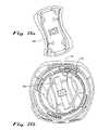
- FIG. 10is another exploded perspective view of the cartridge assembly of FIG. 4 .
- FIG. 11is a bottom view of the cartridge assembly of FIG. 10 with the bottom cover removed for clarity.
- FIG. 12is a perspective view of a drive and return mechanism of the lancing device of FIG. 7 .
- FIG. 13is a perspective view of a lancing depth adjustment ring of the lancing device of FIG. 7 .
- FIG. 14is a top view of an actuator button portion of the lancing device of FIG. 7 .
- FIG. 15 ais a detailed plan view of a portion of the advancer mechanism of FIG. 6 located on the bottom of the housing of the lancing device of FIG. 7 .
- FIG. 15 bis a detailed plan view of the advancer mechanism of FIG. 6 , including the portion shown in FIG. 15 a.
- FIG. 16is a perspective view of the cartridge of FIG. 4 installed in the lancing device of FIG. 7 .
- Rangesmay be expressed herein as from “about” or “approximately” one particular value and/or to “about” or “approximately” another particular value. When such a range is expressed, another embodiment includes from the one particular value and/or to the other particular value. Similarly, when values are expressed as approximations, by use of the antecedent “about,” it will be understood that the particular value forms another embodiment.
- the present inventionprovides a lancet cap displacement mechanism that moves a cap, after it has been separated from an active lancet, out of the lancing stroke travel path of the active lancet.
- the cap displacement mechanismis embodied in a replaceable multi-lancet cartridge for use in combination with a multi-use lancing device.
- the cap displacement mechanismis embodied in a multi-use lancing device for use in combination with an improved replaceable multi-lancet cartridge.
- the improvements of the present inventionare adaptable for application in connection with various forms of multi-lancet lancing devices.
- the improvements of the present inventionare of potential application to the multi-lancet lancing devices and replaceable multi-lancet cartridges shown in PCT International Publication No. WO 03/071940 A1 (International Application No. PCT/US03/05159, filed Feb. 20, 2003), which is hereby incorporated herein by reference. It will be recognized that the improvements disclosed herein are of individual advantage, or can be used in combination with one another.
- the lancing device of the present inventioncomprises a housing defining a chamber for receiving the cartridge; a drive mechanism for propelling an active lancet of the cartridge through a lancing stroke, from a retracted position within the cartridge to an advanced position wherein a sharp tip of the active lancet projects through a lancet opening in the housing to pierce the subject's skin at an intended lancing site; a charging mechanism for energizing the drive mechanism; and an advancing mechanism for sequentially advancing lancets of the cartridge into and through the active position.
- Various of these mechanismscan be combined; for example, a single mechanism optionally serves to energize the drive mechanism and simultaneously or sequentially advance the cartridge.
- the lancet cap displacement mechanisms of the present inventionmay be embodied in a variety of styles of lancet cartridges and lancing devices.
- the cap displacement mechanismscan be adapted for use in a cartridge having a radial arrays of lancets (as described herein), a linear array of lancets, a cylindrical array of axially arranged lancets, or other lancet and carrier configurations.
- the cap displacement mechanismscan be adapted for use in disposable multi-lancet lancing devices (without a replaceable cartridge), with the components of the cap displacement mechanisms being elements of the lancing devices.
- FIGS. 1 and 2show a cartridge assembly according to a first example embodiment of the present invention, which as a whole is designated by the reference number 10 .
- the cartridge assembly 10comprises a housing 12 for an array of lancets 20 .
- the housing 12preferably has two portions that connect together, for example, a top portion or cover 14 and a bottom portion or base 16 .
- the top portion 14 and the bottom portion 16preferably comprise generally circular disk-like structures with generally circular central aligned openings.
- the bottom portion 16preferably has guides thereon or therein for engaging and guiding a rotatable carrier disk 18 .
- the top portion 14 and the bottom portion 16collectively form an annular outer shell of the cartridge assembly 10 for containing the carrier 18 and the array of lancets 20 .
- the top cover 14preferably defines a single lancet opening 15 on its outer circumferential rim, through which the tip of an active one of the lancets 20 passes during its lancing stroke.
- the carrier disk 18preferably includes guide channels 19 for permitting radial sliding movement of the lancets 20 in a lancing stroke between a retracted position and an extended position during the lancing operation.
- the guide channels 19may be formed by projections on or recesses in the face of the carrier disk 18 .
- the carrier 18comprises twenty radial guide channels 19 for holding twenty lancets 20 .
- the carrier 18may, however, be provided with more or less guide channels 19 and lancets 20 , as desired.
- the lancets 20are radially arranged in the rotatable carrier disk 18 in the guide channels 19 , and can be driven through their lancing strokes in their axial direction (i.e., along a radius of the carrier disk 18 ) upon actuation of the lancing device.
- the cartridge assembly 10is arranged such that the carrier disk 18 , loaded with the lancets 20 , is rotatably mounted on the bottom portion 16 of the housing 12 .
- the top portion 14 of the housing 12is then secured to the bottom portion 16 , for example by ultrasonic welding, such that the carrier disk 18 and the lancets 20 can rotate within the housing 12 .
- a one-way clutch or ratchet mechanismpreferably limits the rotation of the carrier disk to rotation in a single direction to prevent re-use of a lancet and resultant potential contamination.
- the lancets 20each preferably comprise a needle or blade forming a sharp lancet tip 22 , and a lancet body 24 , and are preferably arranged generally radially in the guide channels 19 of the carrier disk 18 with their tips 22 directed outwardly.
- the lancet body 24is formed of plastic and is injection-molded around the lancet tip 22 .
- Each lancet tip 22is preferably encapsulated by a protective endcap 28 , which may be integrally molded with the lancet body 24 and forms a sterility and safety barrier for the lancet tip.
- the protective cap 28 of each lancet 20is preferably connected to the body 24 by one or more thin segments or a reduced-thickness transition region such as a notch or slit, which forms a weaker separation zone that gives easily so that the cap can be removed.
- the separation zone 30fails and allows the protective cap 28 to easily detach from the lancet body 24 .
- the separation zoneis defined by the gap between the cap and the lancet body.
- Each lancet body 24has a retainer that engages a cooperating structure of the lancing device's drive mechanism (described below) when the lancet is in the active position.
- each lancet body 24may have a retainer foot 26 extending downward from the back of the lancet body 24 to engage a cooperating jaw or other structure of the drive mechanism's reciprocating plunger when the lancet is in the active position.
- the feet 26 of the lancets 20 that are not in the active positionpreferably slide within a curved foot channel in the cartridge bottom housing 16 to constrain the used lancets against movement in the radial direction unless the lancet is in the active position.
- the cartridge bottom housing 16preferably defines a radial lancing channel 17 extending from the curved foot channel at a position corresponding to the lancet opening 15 in the cartridge top housing 14 .
- the active lancetslides in the lancing channel 17 as it is driven along the lancing stroke upon activation or firing of the lancing device.
- cap surfaces 29are engaged and constrained by cooperating cap guide tracks 31 of the carrier 18 .
- the cap surfaces 29may be defined by two shoulders projecting laterally outwardly on opposite sides of the cap 28 , as shown, or by other features such as recesses formed into the caps.
- the cap guide tracks 31hold unused lancets 20 in position on the carrier 18 prior to use, and to hold the cap 28 as the active lancet body 24 is retracted upon charging or energizing of the drive mechanism to detach the cap.
- the cap guide tracks 31preferably define a transverse guide path (i.e., out of the plane of the lancet array, preferably at about 90 degrees relative to the lancing stroke travel path) along which the cap 28 is moved after it is detached from the lancet body 24 .
- This transverse guide pathallows removal of the cap 28 from the path of travel of the active lancet 20 as it is driven through its lancing stroke upon activation.
- the cap guide tracks 31preferably comprise one or more resilient fingers or barbs for guiding the detached cap 28 along the transverse guide path and retaining the cap in its transversely displaced position so that it is prevented from rattling around within the housing 12 or potentially interfering with the device's operation.
- four cap guide track fingers 31may be provided for receiving and guiding the two cap shoulder surfaces 29 , as shown.
- two cap guide track fingersmay be provided for guiding and being received by two cap recessed surfaces.
- the carrier disk 18can optionally be labeled with numbers or other indicia to indicate the number of unused lancets 20 remaining (or alternatively the number of lancets already used).
- the cartridge housing 12preferably has an opening 40 therethrough, and the lancing device has a corresponding opening, such that the user can view the indicia.
- the cartridge 10preferably has a resilient member that is biased into engagement with an underlying lancet 20 in the active position.
- the resilient memberthus prevents said active lancet 20 from being displaced if the cartridge 10 is removed from the lancing device after the device is charged and the cap is detached, at which point the active lancet would otherwise be unconstrained.
- the resilient memberpreferably comprises a resilient tongue portion 41 formed by a pair of cutout slots defined in the top housing cover 14 of the cartridge 10 .
- the carrieris partially indexed within the cartridge housing (for example, a half-step forward or back, to a position between adjacent lancets), when the cartridge is removed from the lancing device, to prevent displacement of an unconstrained lancet from the active position.
- the lancet cap displacement mechanismis provided by a cantilevered spring member 50 that serves to press the detached protective cap 28 of each sequential active lancet 20 along the transverse guide path and out of the radial path of travel of that lancet prior to activation or firing.
- the spring member 50preferably has a first section 52 , a second section 54 , and an intermediate section 56 .
- the first section 52is attached (by conventional fastening structures or techniques) to the inner surface of the top portion 14 of the housing 12 , or to another stationary part of the cartridge 10 .
- the second section 54is configured to engage the protective cap 28 and to push the cap 28 downwardly along the cap guide tracks 31 of the carrier 18 , towards the bottom portion 16 of the housing 12 .
- the intermediate section 56connects the first section 52 to the second section 54 .
- the spring member 50is leaf spring-type spring member, comprising a flexible, resilient piece of metal or other material that does not readily take on a set permanent deformation.
- the first section 52 , the second section 54 , and the intermediate section 56each include an elongated member. And the intermediate section 56 is angled or curved downwardly from the first section 52 to the second section 54 , thereby offsetting the first and second sections.
- the spring member 50rides along the top surface of a lancet's endcap 28 as that lancet is advanced into the active position, and the spring member 50 flexes upwardly and is charged to impart a downward force on the cap. Then upon detachment of the cap 28 from the active lancet 20 by the retraction of the lancet body 24 , the cap is pressed down along the guide tracks 31 under the influence of the charged spring member 50 .
- the leaf spring-type spring member 50is inverted and attached to the housing bottom 16 .
- the member 50is a coil spring, with one end (the first section 52 ) attached to the housing 12 and the other end (the second section 54 ) including a ramped extension panel for riding along the caps as they are rotated to the active position.
- the cartridge assembly 100is substantially similar to the cartridge assembly 10 described above, having a housing 112 with top and bottom sections 114 and 116 , a carrier 118 , and an array of lancets 120 each having a body 124 and a cap 28 .
- the lancet cap displacement mechanismis provided by a spring-biased cam-driven plunger assembly.
- This assemblyincludes a plunger 232 that is positioned at about the cartridge outer perimeter and adjacent (beneath or above) the active lancet position.
- the plunger 232is the form of a pin, shaft, tube, T-member, angle piece, or other elongated structure.
- the plunger 232is ordinarily biased away from the active lancet (e.g., downwardly) under the influence of a spring element 233 .
- the spring element 233may be provided by a cantilevered leaf spring arm that is attached to (and integrally formed with) the plunger 232 , as shown.
- the spring elementmay be provided by a coil spring (e.g., coaxially arranged with the plunger), an elastic member (e.g., rubber band), or other biasing structure.
- the plunger 232extends through an opening 235 in the upper shell 237 of the advancing mechanism 230 , and the spring element 233 is attached to the upper shell and the plunger.
- the spring-biased cam-driven plunger assemblyfurther comprises a cam surface 234 formed, for example, on the lower shell 239 of the advancer mechanism 230 of the lancing device.
- the cam surface 234is generally wedge-shaped, as shown, with two of the wedges arranged at about 180 degrees apart, though other specific shapes, numbers, and spacings of the cams may be used.
- the rising plunger 232pushes the cap 128 upwardly along the cap guide tracks 131 of the carrier disk 118 along the transverse guide path at about 90 degrees relative to the lancing stroke travel path, and out of the radial path of the active lancet's lancing stroke.
- the cap guide tracks 131are preferably resilient members (e.g., barbs or fingers) that retain the cap 128 above the path of travel of the active lancet, as seen best with reference to FIG. 8 .
- Continued actuation of the advancer mechanism 230moves the inclined portion of the cam surface 234 past the plunger 232 , as seen best with reference to FIG. 9 , allowing the plunger to drop back down under the influence of the charged spring arm 233 .
- the plunger 232is now reset and out of the active lancet's path of travel as it is propelled along its lancing stroke.
- the spring-biased, cam-driven plunger assemblymay be provided as part of one or more other components of the lancing device.
- the spring and plungerare attached to and extend upwardly from the housing bottom with the spring biased upwardly to displace the lancet caps.
- the cam surfaceis formed on a rotary element (e.g., rotationally moved by the advancing mechanism) within the lancing device housing. The cam surface may be configured to drive the plunger downwardly away from the active lancet cap except when the lancet is charged and ready for activation, at which position the plunger moves under the influence of the spring to displace the cap.
- the cam surfacemay be defined by two (or another number of) upwardly recessed notches that permit the plunger to move upward to displace the caps.
- the cam surfaceis defined on a stationary element and the plunger is rotated relative to the cam surface for driving the plunger to displace the lancet caps.
- a lancing device 200preferably comprises a clam-shell housing 202 having a top portion 204 hingedly connected to a bottom portion 206 .
- the housing 202defines a lancing opening 208 , preferably through a sidewall portion 210 thereof, that aligns with the lancing opening 15 of an installed cartridge 100 .
- the housing 202preferably also comprises a latch 216 that secures the top 204 of the housing 202 to its bottom 206 .
- the lancing devicepreferably further comprises a drive mechanism, seen best with reference to FIGS. 7 , 12 , and 16 .
- the drive mechanismpreferably includes a reciprocating plunger 250 that engages the active lancet 20 and drives it radially along its lancing stroke upon activation or firing of the device, through an advanced position where the lancet tip punctures the subject's skin, and back to a retracted position where the lancet tip is shielded within the cartridge.
- the plunger 250preferably comprises a recess forming a jaw 256 for receiving and engaging the foot 26 of the active lancet.
- two springsoperate in tandem to drive and return the plunger 250 upon activation of the lancing device by pressing the activating button 220 .
- the springscan be, for example, coil springs, leaf springs, torsion springs, spiral springs, or the like, including other biasing mechanisms.
- the drive spring 252is the stronger of the two springs, and drives the active lancet from its initial position into its extended position.
- the return spring 254serves to retract the active lancet after lancing the skin.
- One or more limit memberssuch as posts or lugs optionally interact with one or both springs, and/or with other portion(s) of the drive mechanism, to more precisely define the equilibrium, retracted, and/or extended position(s) of the plunger. Because the jaw 256 of the plunger is open to the top, it securely but releasably engages the foot 26 of the active lancet to drive the lancet along its lancing stroke, yet allows the cartridge to be removed and replaced at any point during its use.
- the plunger 250preferably further comprises a flexible release arm 253 having a catch portion 255 that retains the plunger in its armed state, with drive spring 252 energized prior to activation, and is released by the activating button upon actuation to propel the active lancet through its lancing stroke.
- the lancing devicepreferably further comprises a mechanism for depth control, in one embodiment a depth-control ring 212 , shown in detail by FIG. 13 .
- the depth ring 212is positioned near the perimeter of the housing 202 of the lancing device 204 , and generally follows the contour of the housing of the lancing device 200 .
- the depth ring 212defines a plurality of openings 214 A, 214 B . . . 214 N (collectively, the “openings 214 ”) therethrough, through which the tip of a lancet 20 is driven to pierce a skin surface of the subject to obtain a sample of blood.
- the openings 214vary in diameter and/or in the depth to which their outer contact surfaces are recessed or countersunk.
- the depth ring 212is rotated by the user to selectively position a particular opening 214 in alignment with the puncture position 208 , thereby controlling the depth of penetration of the lancet tip into the subject's skin. Because the openings can vary in diameter and in recess depth, the depth ring 212 provides a wide range of depth control.
- the travel of the lancet 20preferably is not affected by variation of the position of the depth ring 212 , and so the lancing stroke preferably remains uniform regardless of the depth control position.
- the lancing devicepreferably further comprises an activating button positioned on the top half-shell 204 of the housing 202 for activating the drive mechanism to propel the active lancet through its lancing stroke.
- An example configuration of the activating button member 220is shown in FIG. 14 .
- the activating button member 220preferably includes a button portion 222 , which releases the catch portion 255 of the plunger release arm when pressed by the user to activate or fire the device.
- the activating button member 220preferably further comprises one or more integral spring arms 224 for biasing the button 222 outwardly.
- the activating button member 220preferably further comprises a retainer ring for securing the depth control ring 212 in place.
- the lancing device 200preferably further comprises an advancer mechanism 230 as seen best with reference to FIGS. 8 , 9 , 15 a , 15 b , and 16 .
- the advancer mechanism 230generally comprises a manually-rotatable element that is operable to advance the carrier to move sequential lancets 20 of a lancet cartridge 118 into the active position.
- a fingerpreferably projects from the advancer mechanism 230 through a slot in the bottom housing of the lancet cartridge to engage and advance the lancet carrier through indexed rotational increments corresponding to one lancet position, while the outer housing of the lancet cartridge remains fixed in position.
- Actuation of the advancer mechanism 230preferably also functions to engage the active lancet in the jaw of the plunger and retract the plunger to de-cap the active lancet and energize or arm the drive mechanism.
- Actuation of the advancer mechanism 230may also serve to drive the spring-biased cam-driven plunger 232 , as described above, if implementing the second example embodiment.
- the advancer mechanism 230is operable to rotate in one direction only and in discrete increments (e.g., 180° increments).
- Guide channels or ribs 231 formed in or on the inner face of the advancer mechanismact as cam paths to engage a cooperating follower element of the drive mechanism to retract the drive plunger 250 into its armed state, with drive spring 252 energized.
- the guide channels or ribs 231are contoured to retract the plunger 250 more slowly at the beginning of the advancing stroke, while the endcap 28 is being detached from the lancet, providing mechanical advantage for smoother and easier operation.
- a ratchet mechanism 234may be provided to prevent reverse rotation of the advancer mechanism.
- a locating pinis driven upwardly (as by a cam surface similar to the motion of plunger 232 described above) through an opening in the cartridge housing and engaged within a yoke 122 (see FIGS. 10 and 11 ) between lancet paths on the carrier disk 118 , to more precisely position the active lancet and prevent further movement of the carrier disk until the lancing device is fired.
- the carrier 118comprises a groove 124 that engages a pin on the bottom portion of the housing of the cartridge assembly when all the lancets have been used. This groove and pin combination prevents the cartridge 100 from being moved in either direction after all of the lancets have been used, and thereby prevent a reuse of a non-sterile lancet.
- the userpreferably releases a latch 216 to open the lancing device 200 .
- the userthen places a preassembled multi-lancet cartridge 100 into the lancing device 200 and closes and latches the housing 202 .
- the userturns the advancer mechanism 230 through a 180° stroke.
- the carrier 118is indexed by one lancet position, thus indexing an unused lancet 20 into the active position.
- the plunger 250engages foot 26 of the lancet and pulls the lancet radially inwardly. This step energizes the drive spring of the drive mechanism.
- the catch 255 of the plungerengages a cooperating surface feature of the housing, and the lancet is now in the energized or armed position.
- the cap 28As the lancet 20 is retracted radially inward to charge the drive spring, the cap 28 is held and prevented from moving radially inward with the lancet by the guide track (e.g., detents, fingers, or barbs) 119 . In this way, the lancet cap 28 is separated from the lancet body 24 . Then the cap displacement mechanism then moves the disengaged cap out of the travel path of the active lancet.
- the spring arm 50engages and moves the detached cap 28 out of the lancing stroke path where the cap is held by the guide track, and then the spring element returns to its reset or rest position clear of the lancing stroke.
- the spring-biased cam-driven plunger 232engages and moves the detached cap 28 out of the path of travel of the active lancet, then clears the cam and is biased back to its rest or reset position.
- the guide tracke.g., detents, fingers, or barbs
- the guide trackcapture the cap 28 and hold it above the path the lancet 20 will travel in the lancing stroke.
- the usermay adjust the depth ring 212 to the desired setting to vary the penetration depth. If present, the position lock pin is raised into engagement with the yoke 122 of the cartridge 118 to prevent further movement of the cartridge until activated or fired to release the active lancet to traverse its lancing stroke.
- the lancing device 200is positioned against a finger or other part of the subject's body.
- the activation button 220is pressed, releasing the catch 255 of the plunger and allowing the drive spring 252 to drive the plunger 250 and the active lancet engaged in the jaw thereof along a controlled radial path, through an extended position where the lancet tip punctures the subject's skin at the lancing site.
- the lancetis preferably guided throughout its lancing stroke along three sides by the guide channels of the carrier 118 and on the fourth side by the cartridge housing.
- the return spring 254energized to bias the plunger 250 and retract the lancet inwardly to a retracted position within the lancet cartridge.
Landscapes
- Health & Medical Sciences (AREA)
- Life Sciences & Earth Sciences (AREA)
- Physics & Mathematics (AREA)
- Heart & Thoracic Surgery (AREA)
- Molecular Biology (AREA)
- Pathology (AREA)
- Engineering & Computer Science (AREA)
- Biomedical Technology (AREA)
- Hematology (AREA)
- Medical Informatics (AREA)
- Biophysics (AREA)
- Surgery (AREA)
- Animal Behavior & Ethology (AREA)
- General Health & Medical Sciences (AREA)
- Public Health (AREA)
- Veterinary Medicine (AREA)
- Geometry (AREA)
- Dermatology (AREA)
- Measurement Of The Respiration, Hearing Ability, Form, And Blood Characteristics Of Living Organisms (AREA)
Abstract
Description
Claims (25)
Priority Applications (4)
| Application Number | Priority Date | Filing Date | Title |
|---|---|---|---|
| US11/107,984US7377904B2 (en) | 2004-04-16 | 2005-04-15 | Cap displacement mechanism for lancing device and multi-lancet cartridge |
| US11/931,023US8298255B2 (en) | 2004-04-16 | 2007-10-31 | Cap displacement mechanism for lancing device and multi-lancet cartridge |
| US11/932,309US20080058849A1 (en) | 2004-04-16 | 2007-10-31 | Cap displacement mechanism for lancing device and multi-lancet cartridge |
| US13/928,492US20130289598A1 (en) | 2004-04-16 | 2013-06-27 | Cap displacement mechanism for lancing device and multi-lancet cartridge |
Applications Claiming Priority (2)
| Application Number | Priority Date | Filing Date | Title |
|---|---|---|---|
| US56271204P | 2004-04-16 | 2004-04-16 | |
| US11/107,984US7377904B2 (en) | 2004-04-16 | 2005-04-15 | Cap displacement mechanism for lancing device and multi-lancet cartridge |
Related Child Applications (3)
| Application Number | Title | Priority Date | Filing Date |
|---|---|---|---|
| US57137806AContinuation-In-Part | 2004-06-30 | 2006-12-28 | |
| US11/931,023DivisionUS8298255B2 (en) | 2004-04-16 | 2007-10-31 | Cap displacement mechanism for lancing device and multi-lancet cartridge |
| US11/932,309DivisionUS20080058849A1 (en) | 2004-04-16 | 2007-10-31 | Cap displacement mechanism for lancing device and multi-lancet cartridge |
Publications (2)
| Publication Number | Publication Date |
|---|---|
| US20050234494A1 US20050234494A1 (en) | 2005-10-20 |
| US7377904B2true US7377904B2 (en) | 2008-05-27 |
Family
ID=34966023
Family Applications (4)
| Application Number | Title | Priority Date | Filing Date |
|---|---|---|---|
| US11/107,984Expired - LifetimeUS7377904B2 (en) | 2004-04-16 | 2005-04-15 | Cap displacement mechanism for lancing device and multi-lancet cartridge |
| US11/931,023Active2029-02-12US8298255B2 (en) | 2004-04-16 | 2007-10-31 | Cap displacement mechanism for lancing device and multi-lancet cartridge |
| US11/932,309AbandonedUS20080058849A1 (en) | 2004-04-16 | 2007-10-31 | Cap displacement mechanism for lancing device and multi-lancet cartridge |
| US13/928,492AbandonedUS20130289598A1 (en) | 2004-04-16 | 2013-06-27 | Cap displacement mechanism for lancing device and multi-lancet cartridge |
Family Applications After (3)
| Application Number | Title | Priority Date | Filing Date |
|---|---|---|---|
| US11/931,023Active2029-02-12US8298255B2 (en) | 2004-04-16 | 2007-10-31 | Cap displacement mechanism for lancing device and multi-lancet cartridge |
| US11/932,309AbandonedUS20080058849A1 (en) | 2004-04-16 | 2007-10-31 | Cap displacement mechanism for lancing device and multi-lancet cartridge |
| US13/928,492AbandonedUS20130289598A1 (en) | 2004-04-16 | 2013-06-27 | Cap displacement mechanism for lancing device and multi-lancet cartridge |
Country Status (5)
| Country | Link |
|---|---|
| US (4) | US7377904B2 (en) |
| EP (1) | EP1742574B1 (en) |
| JP (1) | JP4944770B2 (en) |
| CA (1) | CA2562353C (en) |
| WO (1) | WO2005102168A1 (en) |
Cited By (32)
| Publication number | Priority date | Publication date | Assignee | Title |
|---|---|---|---|---|
| US20060224172A1 (en)* | 2003-08-20 | 2006-10-05 | Facet Technologies, Llc | Blood sampling device |
| US20070202338A1 (en)* | 2004-06-01 | 2007-08-30 | Sullivan Michael H | Method for hardening at a surface a component, devices having one or more hardened surfaces and devices for retaining and representing for use a plurality of components |
| US20080058849A1 (en)* | 2004-04-16 | 2008-03-06 | Conway William E | Cap displacement mechanism for lancing device and multi-lancet cartridge |
| US20090312722A1 (en)* | 2005-08-04 | 2009-12-17 | Laurent Philippe E | Injection fluid leakage collection system and method |
| US20090321467A1 (en)* | 2006-05-09 | 2009-12-31 | Becton Dickinson And Company | Method and apparatus for dispensing diagnostic test strips |
| US20100049232A1 (en)* | 2008-08-25 | 2010-02-25 | Abbott Diabetes Care Inc. | Collapsible lancing device |
| US20100094325A1 (en)* | 2007-05-16 | 2010-04-15 | Ahmet Konya | Pricking system |
| US20100229386A1 (en)* | 2009-03-11 | 2010-09-16 | Emerson Climate Technologies, Inc. | Powder metal scrolls and sinter-brazing methods for making the same |
| US20100285386A1 (en)* | 2009-05-08 | 2010-11-11 | Treadstone Technologies, Inc. | High power fuel stacks using metal separator plates |
| US20110027908A1 (en)* | 2009-07-31 | 2011-02-03 | Invisible Sentinel | Device for detection of antigens and uses thereof |
| US20110052410A1 (en)* | 2002-01-24 | 2011-03-03 | Emerson Climate Technologies, Inc. | Powder metal scrolls |
| US20110130782A1 (en)* | 2009-07-10 | 2011-06-02 | Kan Gil | Advancement mechanism for cartridge-based devices |
| US20110144463A1 (en)* | 2008-02-27 | 2011-06-16 | Benny Pesach | Device, system and method for modular analyte monitoring |
| US20110189898A1 (en)* | 2010-02-03 | 2011-08-04 | Lotes Co., Ltd. | Electrical Connector |
| US20110229360A1 (en)* | 2007-01-26 | 2011-09-22 | Emerson Climate Technologies, Inc. | Powder metal scroll hub joint |
| US8221332B2 (en) | 2003-11-12 | 2012-07-17 | Facet Technologies, Llc | Multi-lancet cartridge and lancing device |
| US8353812B2 (en) | 2008-06-04 | 2013-01-15 | Neovista, Inc. | Handheld radiation delivery system |
| US8852123B2 (en) | 2010-12-30 | 2014-10-07 | Roche Diagnostics Operations, Inc. | Handheld medical diagnostic devices housing with sample transfer |
| US9347938B2 (en) | 2012-03-09 | 2016-05-24 | Invisible Sentinel, Inc. | Methods for detecting multiple analytes with a single signal |
| US9475049B2 (en) | 2009-07-31 | 2016-10-25 | Invisible Sentinel, Inc. | Analyte detection devices, multiplex and tabletop devices for detection of analyte, and uses thereof |
| US9486164B2 (en) | 2010-12-30 | 2016-11-08 | Roche Diabetes Care, Inc. | Handheld medical diagnostic device with lancet and sample transfer |
| US9557330B2 (en) | 2009-10-09 | 2017-01-31 | Invisible Sentinel, Inc. | Device for detection of analytes and uses thereof |
| US20170102673A1 (en)* | 2015-10-11 | 2017-04-13 | Zahra Aboutalebi | Magic gluco-wrist watch (mgw) |
| US9717452B2 (en) | 2010-12-30 | 2017-08-01 | Roche Diabetes Care, Inc. | Handheld medical diagnostic devices with lancing speed control |
| US10842427B2 (en) | 2005-09-30 | 2020-11-24 | Intuity Medical, Inc. | Body fluid sampling arrangements |
| US11002743B2 (en) | 2009-11-30 | 2021-05-11 | Intuity Medical, Inc. | Calibration material delivery devices and methods |
| US11045125B2 (en) | 2008-05-30 | 2021-06-29 | Intuity Medical, Inc. | Body fluid sampling device-sampling site interface |
| US11051734B2 (en) | 2011-08-03 | 2021-07-06 | Intuity Medical, Inc. | Devices and methods for body fluid sampling and analysis |
| US11399744B2 (en) | 2008-06-06 | 2022-08-02 | Intuity Medical, Inc. | Detection meter and mode of operation |
| US11419532B2 (en) | 2005-06-13 | 2022-08-23 | Intuity Medical, Inc. | Analyte detection devices and methods with hematocrit/volume correction and feedback control |
| US11986298B2 (en) | 2005-09-30 | 2024-05-21 | Intuity Medical, Inc. | Devices and methods for facilitating fluid transport |
| US11986293B2 (en) | 2008-06-06 | 2024-05-21 | Intuity Medical, Inc. | Medical diagnostic devices and methods |
Families Citing this family (91)
| Publication number | Priority date | Publication date | Assignee | Title |
|---|---|---|---|---|
| US6036924A (en) | 1997-12-04 | 2000-03-14 | Hewlett-Packard Company | Cassette of lancet cartridges for sampling blood |
| US6391005B1 (en) | 1998-03-30 | 2002-05-21 | Agilent Technologies, Inc. | Apparatus and method for penetration with shaft having a sensor for sensing penetration depth |
| DE10057832C1 (en) | 2000-11-21 | 2002-02-21 | Hartmann Paul Ag | Blood analysis device has syringe mounted in casing, annular mounting carrying needles mounted behind test strip and being swiveled so that needle can be pushed through strip and aperture in casing to take blood sample |
| US8641644B2 (en) | 2000-11-21 | 2014-02-04 | Sanofi-Aventis Deutschland Gmbh | Blood testing apparatus having a rotatable cartridge with multiple lancing elements and testing means |
| US7749174B2 (en) | 2001-06-12 | 2010-07-06 | Pelikan Technologies, Inc. | Method and apparatus for lancet launching device intergrated onto a blood-sampling cartridge |
| US8337419B2 (en) | 2002-04-19 | 2012-12-25 | Sanofi-Aventis Deutschland Gmbh | Tissue penetration device |
| JP4272051B2 (en) | 2001-06-12 | 2009-06-03 | ペリカン テクノロジーズ インコーポレイテッド | Blood sampling apparatus and method |
| JP4209767B2 (en) | 2001-06-12 | 2009-01-14 | ペリカン テクノロジーズ インコーポレイテッド | Self-optimized cutting instrument with adaptive means for temporary changes in skin properties |
| WO2002101359A2 (en) | 2001-06-12 | 2002-12-19 | Pelikan Technologies, Inc. | Integrated blood sampling analysis system with multi-use sampling module |
| AU2002344825A1 (en) | 2001-06-12 | 2002-12-23 | Pelikan Technologies, Inc. | Method and apparatus for improving success rate of blood yield from a fingerstick |
| US7981056B2 (en) | 2002-04-19 | 2011-07-19 | Pelikan Technologies, Inc. | Methods and apparatus for lancet actuation |
| US9226699B2 (en) | 2002-04-19 | 2016-01-05 | Sanofi-Aventis Deutschland Gmbh | Body fluid sampling module with a continuous compression tissue interface surface |
| US7344507B2 (en) | 2002-04-19 | 2008-03-18 | Pelikan Technologies, Inc. | Method and apparatus for lancet actuation |
| US9795747B2 (en) | 2010-06-02 | 2017-10-24 | Sanofi-Aventis Deutschland Gmbh | Methods and apparatus for lancet actuation |
| EP1395185B1 (en) | 2001-06-12 | 2010-10-27 | Pelikan Technologies Inc. | Electric lancet actuator |
| US7041068B2 (en) | 2001-06-12 | 2006-05-09 | Pelikan Technologies, Inc. | Sampling module device and method |
| US9427532B2 (en) | 2001-06-12 | 2016-08-30 | Sanofi-Aventis Deutschland Gmbh | Tissue penetration device |
| US7344894B2 (en) | 2001-10-16 | 2008-03-18 | Agilent Technologies, Inc. | Thermal regulation of fluidic samples within a diagnostic cartridge |
| US7004928B2 (en) | 2002-02-08 | 2006-02-28 | Rosedale Medical, Inc. | Autonomous, ambulatory analyte monitor or drug delivery device |
| US7524293B2 (en) | 2002-04-19 | 2009-04-28 | Pelikan Technologies, Inc. | Method and apparatus for penetrating tissue |
| US7410468B2 (en) | 2002-04-19 | 2008-08-12 | Pelikan Technologies, Inc. | Method and apparatus for penetrating tissue |
| US8267870B2 (en) | 2002-04-19 | 2012-09-18 | Sanofi-Aventis Deutschland Gmbh | Method and apparatus for body fluid sampling with hybrid actuation |
| US7582099B2 (en) | 2002-04-19 | 2009-09-01 | Pelikan Technologies, Inc | Method and apparatus for penetrating tissue |
| US7491178B2 (en) | 2002-04-19 | 2009-02-17 | Pelikan Technologies, Inc. | Method and apparatus for penetrating tissue |
| US7371247B2 (en) | 2002-04-19 | 2008-05-13 | Pelikan Technologies, Inc | Method and apparatus for penetrating tissue |
| US9248267B2 (en) | 2002-04-19 | 2016-02-02 | Sanofi-Aventis Deustchland Gmbh | Tissue penetration device |
| US7674232B2 (en) | 2002-04-19 | 2010-03-09 | Pelikan Technologies, Inc. | Method and apparatus for penetrating tissue |
| US7291117B2 (en) | 2002-04-19 | 2007-11-06 | Pelikan Technologies, Inc. | Method and apparatus for penetrating tissue |
| US7648468B2 (en) | 2002-04-19 | 2010-01-19 | Pelikon Technologies, Inc. | Method and apparatus for penetrating tissue |
| US8702624B2 (en) | 2006-09-29 | 2014-04-22 | Sanofi-Aventis Deutschland Gmbh | Analyte measurement device with a single shot actuator |
| US7563232B2 (en) | 2002-04-19 | 2009-07-21 | Pelikan Technologies, Inc. | Method and apparatus for penetrating tissue |
| US7909778B2 (en) | 2002-04-19 | 2011-03-22 | Pelikan Technologies, Inc. | Method and apparatus for penetrating tissue |
| US7331931B2 (en) | 2002-04-19 | 2008-02-19 | Pelikan Technologies, Inc. | Method and apparatus for penetrating tissue |
| US7708701B2 (en) | 2002-04-19 | 2010-05-04 | Pelikan Technologies, Inc. | Method and apparatus for a multi-use body fluid sampling device |
| US7232451B2 (en) | 2002-04-19 | 2007-06-19 | Pelikan Technologies, Inc. | Method and apparatus for penetrating tissue |
| US7297122B2 (en) | 2002-04-19 | 2007-11-20 | Pelikan Technologies, Inc. | Method and apparatus for penetrating tissue |
| US7717863B2 (en) | 2002-04-19 | 2010-05-18 | Pelikan Technologies, Inc. | Method and apparatus for penetrating tissue |
| US8221334B2 (en) | 2002-04-19 | 2012-07-17 | Sanofi-Aventis Deutschland Gmbh | Method and apparatus for penetrating tissue |
| US7547287B2 (en) | 2002-04-19 | 2009-06-16 | Pelikan Technologies, Inc. | Method and apparatus for penetrating tissue |
| US8360992B2 (en) | 2002-04-19 | 2013-01-29 | Sanofi-Aventis Deutschland Gmbh | Method and apparatus for penetrating tissue |
| US9795334B2 (en) | 2002-04-19 | 2017-10-24 | Sanofi-Aventis Deutschland Gmbh | Method and apparatus for penetrating tissue |
| US8372016B2 (en) | 2002-04-19 | 2013-02-12 | Sanofi-Aventis Deutschland Gmbh | Method and apparatus for body fluid sampling and analyte sensing |
| US7901362B2 (en) | 2002-04-19 | 2011-03-08 | Pelikan Technologies, Inc. | Method and apparatus for penetrating tissue |
| US7374544B2 (en) | 2002-04-19 | 2008-05-20 | Pelikan Technologies, Inc. | Method and apparatus for penetrating tissue |
| US9314194B2 (en) | 2002-04-19 | 2016-04-19 | Sanofi-Aventis Deutschland Gmbh | Tissue penetration device |
| US8579831B2 (en) | 2002-04-19 | 2013-11-12 | Sanofi-Aventis Deutschland Gmbh | Method and apparatus for penetrating tissue |
| US8784335B2 (en) | 2002-04-19 | 2014-07-22 | Sanofi-Aventis Deutschland Gmbh | Body fluid sampling device with a capacitive sensor |
| US7892183B2 (en) | 2002-04-19 | 2011-02-22 | Pelikan Technologies, Inc. | Method and apparatus for body fluid sampling and analyte sensing |
| US7141058B2 (en) | 2002-04-19 | 2006-11-28 | Pelikan Technologies, Inc. | Method and apparatus for a body fluid sampling device using illumination |
| US7481776B2 (en) | 2002-04-19 | 2009-01-27 | Pelikan Technologies, Inc. | Method and apparatus for penetrating tissue |
| US7229458B2 (en) | 2002-04-19 | 2007-06-12 | Pelikan Technologies, Inc. | Method and apparatus for penetrating tissue |
| US7976476B2 (en) | 2002-04-19 | 2011-07-12 | Pelikan Technologies, Inc. | Device and method for variable speed lancet |
| US8574895B2 (en) | 2002-12-30 | 2013-11-05 | Sanofi-Aventis Deutschland Gmbh | Method and apparatus using optical techniques to measure analyte levels |
| DE602004028463D1 (en) | 2003-05-30 | 2010-09-16 | Pelikan Technologies Inc | METHOD AND DEVICE FOR INJECTING LIQUID |
| US7850621B2 (en) | 2003-06-06 | 2010-12-14 | Pelikan Technologies, Inc. | Method and apparatus for body fluid sampling and analyte sensing |
| WO2006001797A1 (en) | 2004-06-14 | 2006-01-05 | Pelikan Technologies, Inc. | Low pain penetrating |
| EP1635700B1 (en) | 2003-06-13 | 2016-03-09 | Sanofi-Aventis Deutschland GmbH | Apparatus for a point of care device |
| US8282576B2 (en) | 2003-09-29 | 2012-10-09 | Sanofi-Aventis Deutschland Gmbh | Method and apparatus for an improved sample capture device |
| EP1680014A4 (en) | 2003-10-14 | 2009-01-21 | Pelikan Technologies Inc | METHOD AND DEVICE FOR A VARIABLE USER INTERFACE |
| US8668656B2 (en) | 2003-12-31 | 2014-03-11 | Sanofi-Aventis Deutschland Gmbh | Method and apparatus for improving fluidic flow and sample capture |
| US7822454B1 (en) | 2005-01-03 | 2010-10-26 | Pelikan Technologies, Inc. | Fluid sampling device with improved analyte detecting member configuration |
| US8057434B2 (en) | 2004-03-31 | 2011-11-15 | Eli Lilly And Company | Injection apparatus having a needle cassette for delivering a pharmaceutical liquid |
| WO2006011062A2 (en) | 2004-05-20 | 2006-02-02 | Albatros Technologies Gmbh & Co. Kg | Printable hydrogel for biosensors |
| US9775553B2 (en) | 2004-06-03 | 2017-10-03 | Sanofi-Aventis Deutschland Gmbh | Method and apparatus for a fluid sampling device |
| WO2005120365A1 (en) | 2004-06-03 | 2005-12-22 | Pelikan Technologies, Inc. | Method and apparatus for a fluid sampling device |
| DE102004042886A1 (en)* | 2004-09-04 | 2006-03-30 | Roche Diagnostics Gmbh | Lancet device for creating a puncture wound |
| US8652831B2 (en) | 2004-12-30 | 2014-02-18 | Sanofi-Aventis Deutschland Gmbh | Method and apparatus for analyte measurement test time |
| USD581533S1 (en)* | 2005-04-15 | 2008-11-25 | Facet Technologies, Llc | Multi-lancet lancing device |
| USD605290S1 (en) | 2005-04-15 | 2009-12-01 | Facet Technologies, Llc | Multi-lancet cartridge for a lancing device |
| EP1996914B1 (en)* | 2006-03-10 | 2016-04-27 | Sanofi-Aventis Deutschland GmbH | Method for loading penetrating members in a collection device during manufacture |
| EP1967139A1 (en)* | 2007-03-09 | 2008-09-10 | Roche Diagnostics GmbH | Disposable puncturing device and resuable handling device for a puncturing device |
| EP1974667A1 (en)* | 2007-03-29 | 2008-10-01 | Roche Diagnostics GmbH | Piercing system |
| US20100152660A1 (en)* | 2007-05-30 | 2010-06-17 | Eli Lilly And Company | Cartridge with multiple injection needles for a medication injection device |
| GB0715803D0 (en)* | 2007-08-14 | 2007-09-26 | Owen Mumford Ltd | Lancing devices |
| EP2265324B1 (en) | 2008-04-11 | 2015-01-28 | Sanofi-Aventis Deutschland GmbH | Integrated analyte measurement system |
| US9375169B2 (en) | 2009-01-30 | 2016-06-28 | Sanofi-Aventis Deutschland Gmbh | Cam drive for managing disposable penetrating member actions with a single motor and motor and control system |
| PL2218399T3 (en) | 2009-02-17 | 2014-03-31 | Hoffmann La Roche | Reuse protection for lancet system |
| EP2236082B1 (en) | 2009-04-03 | 2011-11-30 | Roche Diagnostics GmbH | Device to obtain and analyse a blood sample |
| CN101987220B (en)* | 2009-07-30 | 2013-11-13 | 德昌电机(深圳)有限公司 | Needle driving assembly for medical instrument |
| EP2316338A1 (en)* | 2009-11-02 | 2011-05-04 | Roche Diagnostics GmbH | Lancet hook for use in a lancet device |
| US8965476B2 (en) | 2010-04-16 | 2015-02-24 | Sanofi-Aventis Deutschland Gmbh | Tissue penetration device |
| CA2803797A1 (en) | 2010-06-25 | 2011-12-29 | Intuity Medical, Inc. | Analyte monitoring methods and systems |
| US9167992B2 (en)* | 2010-11-03 | 2015-10-27 | Roche Diabetes Care, Inc. | Lancet drive system depth control method and test strip location methods |
| AU2011329876B2 (en)* | 2010-11-19 | 2014-09-18 | Eli Lilly And Company | Needle magazine for medication injection device |
| DE102011015656B3 (en)* | 2011-03-30 | 2012-06-21 | Gerresheimer Regensburg Gmbh | Lancet magazine for lancing devices |
| DK2802265T3 (en) | 2012-01-10 | 2016-02-15 | Sanofi Aventis Deutschland | Device that includes the lancet |
| WO2014205412A1 (en) | 2013-06-21 | 2014-12-24 | Intuity Medical, Inc. | Analyte monitoring system with audible feedback |
| WO2015056914A1 (en)* | 2013-10-18 | 2015-04-23 | 최인상 | Multi-lancet cartridge and multi-lancet driving apparatus |
| KR101513687B1 (en)* | 2013-10-18 | 2015-04-22 | 최인상 | Multi lancet cartridge |
| TWI571635B (en)* | 2014-11-07 | 2017-02-21 | 光寶電子(廣州)有限公司 | Blood glucose detecting device |
| USD896365S1 (en)* | 2019-06-24 | 2020-09-15 | Mark Sipe | Medical port disc |
Citations (130)
| Publication number | Priority date | Publication date | Assignee | Title |
|---|---|---|---|---|
| US3760809A (en) | 1971-10-22 | 1973-09-25 | Damon Corp | Surgical lancet having casing |
| USD245040S (en) | 1976-02-25 | 1977-07-12 | Ryder International Corporation | Surgical lancet |
| US4627445A (en) | 1985-04-08 | 1986-12-09 | Garid, Inc. | Glucose medical monitoring system |
| US4643189A (en) | 1985-02-19 | 1987-02-17 | W. T. Associates | Apparatus for implementing a standardized skin incision |
| USD297978S (en) | 1985-08-16 | 1988-10-04 | Baxter Travenol Laboratories, Inc. | Automatic retractable lancet for bleed time determination |
| US4787398A (en) | 1985-04-08 | 1988-11-29 | Garid, Inc. | Glucose medical monitoring system |
| US4794926A (en) | 1986-11-24 | 1989-01-03 | Invictus, Inc. | Lancet cartridge |
| US4823806A (en) | 1985-11-18 | 1989-04-25 | Serge Bajada | Apparatus for testing the sensory system on humans or animals |
| US4869249A (en) | 1987-05-01 | 1989-09-26 | Owen Mumford Limited | Blood sampling devices |
| US4892097A (en) | 1988-02-09 | 1990-01-09 | Ryder International Corporation | Retractable finger lancet |
| US4983178A (en) | 1988-11-14 | 1991-01-08 | Invictus, Inc. | Lancing device |
| US4995402A (en) | 1988-10-12 | 1991-02-26 | Thorne, Smith, Astill Technologies, Inc. | Medical droplet whole blood and like monitoring |
| US5035704A (en) | 1989-03-07 | 1991-07-30 | Lambert Robert D | Blood sampling mechanism |
| EP0449525A1 (en) | 1990-03-26 | 1991-10-02 | Cascade Medical, Inc. | Medical diagnostic system |
| US5152775A (en) | 1990-10-04 | 1992-10-06 | Norbert Ruppert | Automatic lancet device and method of using the same |
| US5196025A (en) | 1990-05-21 | 1993-03-23 | Ryder International Corporation | Lancet actuator with retractable mechanism |
| DE4234553A1 (en) | 1991-10-19 | 1993-04-22 | Volker Frese | Instrument for measuring blood glucose content - comprises storage container with test strips, colour scale and lancet with exchangeable needle |
| US5318584A (en) | 1992-04-13 | 1994-06-07 | Boehringer Mannheim Gmbh | Blood lancet device for withdrawing blood for diagnostic purposes |
| US5318583A (en) | 1992-05-05 | 1994-06-07 | Ryder International Corporation | Lancet actuator mechanism |
| EP0433050B1 (en) | 1989-12-12 | 1995-03-01 | Owen Mumford Ltd. | Improvements relating to blood sampling devices |
| US5395388A (en) | 1993-11-15 | 1995-03-07 | Schraga; Steven | Single unit lancet device |
| US5464418A (en) | 1993-12-09 | 1995-11-07 | Schraga; Steven | Reusable lancet device |
| US5477209A (en) | 1992-05-01 | 1995-12-19 | Adonis Incorporated | Remote controlled safety light having increased noise discrimination |
| US5507288A (en) | 1994-05-05 | 1996-04-16 | Boehringer Mannheim Gmbh | Analytical system for monitoring a substance to be analyzed in patient-blood |
| US5514152A (en) | 1994-08-16 | 1996-05-07 | Specialized Health Products, Inc. | Multiple segment encapsulated medical lancing device |
| US5527334A (en) | 1994-05-25 | 1996-06-18 | Ryder International Corporation | Disposable, retractable lancet |
| US5535743A (en) | 1992-12-19 | 1996-07-16 | Boehringer Mannheim Gmbh | Device for the in vivo determination of an optical property of the aqueous humour of the eye |
| US5551422A (en) | 1992-11-09 | 1996-09-03 | Boehringer Mannheim Gmbh | Method and apparatus for analytical determination of glucose in a biological matrix |
| USD376203S (en) | 1994-10-31 | 1996-12-03 | Steven Schraga | Single use lancet |
| US5628765A (en) | 1994-11-29 | 1997-05-13 | Apls Co., Ltd. | Lancet assembly |
| US5628764A (en) | 1995-03-21 | 1997-05-13 | Schraga; Steven | Collar lancet device |
| US5645555A (en) | 1994-07-27 | 1997-07-08 | Ryder International Corporation | Rotary lancet |
| US5692504A (en) | 1993-11-04 | 1997-12-02 | Boehringer Mannheim Gmbh | Method and apparatus for the analysis of glucose in a biological matrix |
| US5710630A (en) | 1994-05-05 | 1998-01-20 | Boehringer Mannheim Gmbh | Method and apparatus for determining glucose concentration in a biological sample |
| US5713352A (en) | 1994-12-21 | 1998-02-03 | Boehringer Mannheim Gmbh | Method for investigating a scattering medium with intensity-modulated light |
| US5734587A (en) | 1993-09-17 | 1998-03-31 | Boehringer Mannheim Gmbh | Method of analyzing clinically relevant liquids and suspensions |
| US5741288A (en) | 1996-06-27 | 1998-04-21 | Chemtrak, Inc. | Re-armable single-user safety finger stick device having reset for multiple use by a single patient |
| US5770454A (en) | 1994-05-19 | 1998-06-23 | Boehringer Mannheim Gmbh | Method and aparatus for determining an analyte in a biological sample |
| US5776157A (en) | 1996-10-02 | 1998-07-07 | Specialized Health Products, Inc. | Lancet apparatus and methods |
| US5786226A (en) | 1995-03-16 | 1998-07-28 | Boehringer Mannheim Gmbh | Quantitative transmission spectroscopy using sample carriers with nets |
| US5797940A (en) | 1997-05-30 | 1998-08-25 | International Technidyne Corporation | Adjustable skin incision device |
| US5825488A (en) | 1995-11-18 | 1998-10-20 | Boehringer Mannheim Gmbh | Method and apparatus for determining analytical data concerning the inside of a scattering matrix |
| US5871494A (en) | 1997-12-04 | 1999-02-16 | Hewlett-Packard Company | Reproducible lancing for sampling blood |
| US5879373A (en) | 1994-12-24 | 1999-03-09 | Boehringer Mannheim Gmbh | System and method for the determination of tissue properties |
| US5951492A (en) | 1996-05-17 | 1999-09-14 | Mercury Diagnostics, Inc. | Methods and apparatus for sampling and analyzing body fluid |
| US5962852A (en) | 1996-01-26 | 1999-10-05 | Roche Diagnostics Gmbh | Process and device for determining an analyte contained in a scattering matrix |
| US5971941A (en) | 1997-12-04 | 1999-10-26 | Hewlett-Packard Company | Integrated system and method for sampling blood and analysis |
| EP0589186B1 (en) | 1992-08-28 | 1999-11-03 | Apls Co., Ltd. | Lancet |
| DE19819407A1 (en) | 1998-04-30 | 1999-11-11 | Hendrik Priebs | Cassette for disposable strip with test spots for e.g. blood sugar measurement |
| US5986770A (en) | 1994-07-30 | 1999-11-16 | Roche Diagnostics Gmbh | Apparatus and method for the optical characterization of the structure and composition of a light scattering sample |
| US5997561A (en) | 1996-02-06 | 1999-12-07 | Roche Diagnostics Gmbh | Skin cutter for painless extraction of small blood amounts |
| US6010519A (en) | 1996-09-24 | 2000-01-04 | International Technidyne Corporation | Incision device capable of automatic assembly and a method of assembly |
| US6036924A (en) | 1997-12-04 | 2000-03-14 | Hewlett-Packard Company | Cassette of lancet cartridges for sampling blood |
| EP0985376A1 (en) | 1998-09-07 | 2000-03-15 | Roche Diagnostics GmbH | Lancet dispenser |
| US6042595A (en) | 1999-03-02 | 2000-03-28 | Apls Co., Ltd. | Lancet apparatus for producing a precisely controlled incision |
| US6071294A (en) | 1997-12-04 | 2000-06-06 | Agilent Technologies, Inc. | Lancet cartridge for sampling blood |
| US6093156A (en) | 1996-12-06 | 2000-07-25 | Abbott Laboratories | Method and apparatus for obtaining blood for diagnostic tests |
| US6099484A (en) | 1996-05-17 | 2000-08-08 | Amira Medical | Methods and apparatus for sampling and analyzing body fluid |
| US6144449A (en) | 1996-01-26 | 2000-11-07 | Boehringer Mannheim Gmbh | Low coherence interferometric device |
| US6156050A (en) | 1997-05-29 | 2000-12-05 | Atrion Medical Products, Inc. | Lancet device |
| US6168606B1 (en) | 1999-11-10 | 2001-01-02 | Palco Labs, Inc. | Single-use lancet device |
| FR2797579A1 (en) | 1999-08-16 | 2001-02-23 | Jean Yves Rouviere | Lancing pen for use by diabetics has hollow body containing disposable lancets |
| US6228100B1 (en)* | 1999-10-25 | 2001-05-08 | Steven Schraga | Multi-use lancet device |
| USD444557S1 (en) | 1999-10-19 | 2001-07-03 | Facet Technologies, Llc | Lancing device |
| WO2001066010A1 (en) | 2000-03-04 | 2001-09-13 | Roche Diagnostics Gmbh | Blood lancet with hygienic tip protection |
| US6306152B1 (en) | 1999-03-08 | 2001-10-23 | Agilent Technologies, Inc. | Lancet device with skin movement control and ballistic preload |
| WO2001064105A9 (en) | 2000-03-02 | 2001-10-25 | Inverness Medical Technology I | Combined lancet and electrochemical analyte-testing apparatus |
| DE10057832C1 (en) | 2000-11-21 | 2002-02-21 | Hartmann Paul Ag | Blood analysis device has syringe mounted in casing, annular mounting carrying needles mounted behind test strip and being swiveled so that needle can be pushed through strip and aperture in casing to take blood sample |
| US20020052618A1 (en) | 2000-10-31 | 2002-05-02 | Hans-Peter Haar | Analytical device with integrated lancet |
| WO2002036010A1 (en) | 2000-10-31 | 2002-05-10 | Roche Diagnostics Gmbh | System for withdrawing blood |
| USD458127S1 (en) | 2001-06-15 | 2002-06-04 | Dart Industries Inc. | Curved hinged clamshell container |
| US6418339B1 (en) | 1997-05-26 | 2002-07-09 | Matthias Essenpreis | Method and apparatus for determining the lines of optimal direction for surgical cuts in the human skin |
| US6432120B1 (en) | 1999-06-18 | 2002-08-13 | Surgilance Pte Ltd. | Lancet assembly |
| US20020120216A1 (en) | 2000-09-26 | 2002-08-29 | Michael Fritz | Lancet system |
| US20020168290A1 (en) | 2002-05-09 | 2002-11-14 | Yuzhakov Vadim V. | Physiological sample collection devices and methods of using the same |
| US20030013992A1 (en) | 2000-02-23 | 2003-01-16 | Takatoshi Uchigaki | Sensor cartridge, sensor feeder, and measuring instrument |
| US6531702B1 (en) | 1999-05-27 | 2003-03-11 | Roche Diagnostics Gmbh | Sample carrier for the IR spectroscopy of sample liquids |
| US6530892B1 (en) | 2001-03-07 | 2003-03-11 | Helen V. Kelly | Automatic skin puncturing system |
| US6540675B2 (en) | 2000-06-27 | 2003-04-01 | Rosedale Medical, Inc. | Analyte monitor |
| US20030073089A1 (en) | 2001-10-16 | 2003-04-17 | Mauze Ganapati R. | Companion cartridge for disposable diagnostic sensing platforms |
| US20030073931A1 (en) | 2001-10-16 | 2003-04-17 | Dirk Boecker | Universal diagnostic platform |
| US20030083685A1 (en) | 2001-06-12 | 2003-05-01 | Freeman Dominique M. | Sampling module device and method |
| US20030088191A1 (en) | 2001-06-12 | 2003-05-08 | Freeman Dominique M. | Blood sampling device with diaphragm actuated lancet |
| US6584335B1 (en) | 1997-08-09 | 2003-06-24 | Roche Diagnostics Gmbh | Analytical device for in vivo analysis in the body of a patient |
| US20030144608A1 (en) | 2001-01-19 | 2003-07-31 | Shinichi Kojima | Lancet-integrated sensor, measurer for lancet-integrated sensor, and catridge |
| US20030144609A1 (en) | 2002-01-31 | 2003-07-31 | Kennedy Gwenn E. | Single use device for blood microsampling |
| WO2003070099A1 (en) | 2002-02-21 | 2003-08-28 | Facet Technologies, Llc | Blood analyzer and pricking device for use in blood analysis |
| US20030185713A1 (en) | 2002-03-29 | 2003-10-02 | Leslie Leonard | Capillary flow for a heterogenous assay in a micro-channel environment |
| US20030199909A1 (en) | 2002-04-19 | 2003-10-23 | Pelikan Technologies, Inc. | Method and apparatus for penetrating tissue |
| US20030199898A1 (en) | 2002-04-19 | 2003-10-23 | Pelikan Technologies, Inc. | Method and apparatus for penetrating tissue |
| US20030199905A1 (en) | 2002-04-19 | 2003-10-23 | Pelikan Technologies, Inc. | Method and apparatus for penetrating tissue |
| US20030199789A1 (en) | 2002-04-19 | 2003-10-23 | Pelikan Technologies, Inc. | Method and apparatus for penetrating tissue |
| US20030199894A1 (en) | 2002-04-19 | 2003-10-23 | Pelikan Technologies, Inc. | Method and apparatus for a multi-use body fluid sampling device with optical analyte sensing |
| US20030199904A1 (en) | 2002-04-19 | 2003-10-23 | Pelikan Technologies, Inc. | Method and apparatus for penetrating tissue |
| US20030199908A1 (en) | 2002-04-19 | 2003-10-23 | Pelikan Technologies, Inc. | Method and apparatus for penetrating tissue |
| US20030199897A1 (en) | 2002-04-19 | 2003-10-23 | Pelikan Technologies, Inc. | Method and apparatus for penetrating tissue |
| US20030199911A1 (en) | 2002-04-19 | 2003-10-23 | Pelikan Technologies, Inc. | Method and apparatus for penetrating tissue |
| US20030199791A1 (en) | 2002-04-19 | 2003-10-23 | Pelikan Technologies, Inc. | Method and apparatus for penetrating tissue |
| US20030199900A1 (en) | 2002-04-19 | 2003-10-23 | Pelikan Technologies, Inc. | Method and apparatus for penetrating tissue |
| US20030199906A1 (en) | 2002-04-19 | 2003-10-23 | Pelikan Technologies, Inc. | Method and apparatus for penetrating tissue |
| US20030199902A1 (en) | 2002-04-19 | 2003-10-23 | Pelikan Technologies, Inc. | Method and apparatus for penetrating tissue |
| US20030199907A1 (en) | 2002-04-19 | 2003-10-23 | Pelikan Technologies, Inc. | Method and apparatus for penetrating tissue |
| US20030199910A1 (en) | 2002-04-19 | 2003-10-23 | Pelikan Technologies, Inc. | Method and apparatus for penetrating tissue |
| US20030199899A1 (en) | 2002-04-19 | 2003-10-23 | Pelikan Technologies, Inc. | Method and apparatus for penetrating tissue |
| US20030199903A1 (en) | 2002-04-19 | 2003-10-23 | Pelikan Technologies, Inc. | Method and apparatus for penetrating tissue |
| US20030199901A1 (en) | 2002-04-19 | 2003-10-23 | Pelikan Technologies, Inc. | Method and apparatus for penetrating tissue |
| US20030199895A1 (en) | 2002-04-19 | 2003-10-23 | Pelikan Technologies, Inc. | Method and apparatus for penetrating tissue |
| US20030199790A1 (en) | 2002-04-19 | 2003-10-23 | Pelikan Technologies, Inc. | Method and apparatus for penetrating tissue |
| US20030199896A1 (en) | 2002-04-19 | 2003-10-23 | Pelikan Technologies, Inc. | Method and apparatus for penetrating tissue |
| US20030212424A1 (en) | 2002-04-19 | 2003-11-13 | Pelikan Technologies, Inc. | Method and apparatus for lancet actuation |
| US20030211619A1 (en) | 2002-05-09 | 2003-11-13 | Lorin Olson | Continuous strip of fluid sampling and testing devices and methods of making, packaging and using the same |
| US20030212344A1 (en) | 2002-05-09 | 2003-11-13 | Vadim Yuzhakov | Physiological sample collection devices and methods of using the same |
| US20030212347A1 (en) | 2002-05-09 | 2003-11-13 | Borzu Sohrab | Devices and methods for accessing and analyzing physiological fluid |
| US20030212345A1 (en) | 2002-05-09 | 2003-11-13 | Mcallister Devin | Minimal procedure analyte test system |
| EP0877250B1 (en) | 1997-04-28 | 2003-12-03 | Bayer Corporation | Dispensing instrument for fluid monitoring sensors |
| US20030223906A1 (en) | 2002-06-03 | 2003-12-04 | Mcallister Devin | Test strip container system |
| DE10245721A1 (en) | 2002-02-21 | 2003-12-11 | Hartmann Paul Ag | Blood analyzer device comprises needles, test media, analyzer and display, and has carrier turned with respect to main body, to position needle and test media |
| WO2003088835A3 (en) | 2002-04-19 | 2003-12-24 | Pelikan Technologies Inc | Method and apparatus for penetrating tissue |
| US20040010279A1 (en) | 2002-04-19 | 2004-01-15 | Freeman Dominique M. | Device and method for variable speed lancet |
| US20040064068A1 (en) | 2002-09-30 | 2004-04-01 | Denuzzio John D. | Integrated lancet and bodily fluid sensor |
| US20040087990A1 (en) | 2002-04-19 | 2004-05-06 | Pelikan Technologies, Inc. | Method and apparatus for body fluid sampling with hybrid actuation |
| US20040092944A1 (en) | 2002-11-07 | 2004-05-13 | Penenberg Brad L. | Apparatus for, and method of, preparing for and inserting hip joint prosthesis using computer guidance |
| US20040092995A1 (en) | 2002-04-19 | 2004-05-13 | Pelikan Technologies, Inc. | Method and apparatus for body fluid sampling with improved sensing |
| US20040098009A1 (en) | 2002-04-19 | 2004-05-20 | Pelikan Technologies, Inc. | Method and apparatus for body fluid sampling and analyte sensing |
| EP0811843A3 (en) | 1996-06-06 | 2004-06-23 | Bayer Corporation | Fluid testing sensor for use in dispensing instruments |
| US6766817B2 (en) | 2001-07-25 | 2004-07-27 | Tubarc Technologies, Llc | Fluid conduction utilizing a reversible unsaturated siphon with tubarc porosity action |
| US6852119B1 (en) | 2002-09-09 | 2005-02-08 | Ramzi F. Abulhaj | Adjustable disposable lancet and method |
| US6929649B2 (en) | 2002-04-23 | 2005-08-16 | Lifescan, Inc. | Lancing device with automatic stick and return |
| US6988996B2 (en) | 2001-06-08 | 2006-01-24 | Roche Diagnostics Operatons, Inc. | Test media cassette for bodily fluid testing device |
| EP0949506B1 (en) | 1998-04-06 | 2006-03-22 | Bayer Corporation | Method and apparatus for data management authentication in a clinical analyzer |
Family Cites Families (3)
| Publication number | Priority date | Publication date | Assignee | Title |
|---|---|---|---|---|
| WO2005018454A2 (en)* | 2003-08-20 | 2005-03-03 | Facet Technologies, Llc | Multi-lancet device with sterility cap repositioning mechanism |
| US7377904B2 (en)* | 2004-04-16 | 2008-05-27 | Facet Technologies, Llc | Cap displacement mechanism for lancing device and multi-lancet cartridge |
| WO2009075907A2 (en)* | 2007-07-05 | 2009-06-18 | Facet Technologies, Llc | Multi-lancet cartridge and lancing device |
- 2005
- 2005-04-15USUS11/107,984patent/US7377904B2/ennot_activeExpired - Lifetime
- 2005-04-15CACA2562353Apatent/CA2562353C/ennot_activeExpired - Lifetime
- 2005-04-15JPJP2007508571Apatent/JP4944770B2/ennot_activeExpired - Fee Related
- 2005-04-15WOPCT/US2005/012873patent/WO2005102168A1/enactiveApplication Filing
- 2005-04-15EPEP05736400.2Apatent/EP1742574B1/ennot_activeExpired - Lifetime
- 2007
- 2007-10-31USUS11/931,023patent/US8298255B2/enactiveActive
- 2007-10-31USUS11/932,309patent/US20080058849A1/ennot_activeAbandoned
- 2013
- 2013-06-27USUS13/928,492patent/US20130289598A1/ennot_activeAbandoned
Patent Citations (160)
| Publication number | Priority date | Publication date | Assignee | Title |
|---|---|---|---|---|
| US3760809A (en) | 1971-10-22 | 1973-09-25 | Damon Corp | Surgical lancet having casing |
| USD245040S (en) | 1976-02-25 | 1977-07-12 | Ryder International Corporation | Surgical lancet |
| US4643189A (en) | 1985-02-19 | 1987-02-17 | W. T. Associates | Apparatus for implementing a standardized skin incision |
| US4627445A (en) | 1985-04-08 | 1986-12-09 | Garid, Inc. | Glucose medical monitoring system |
| US4787398A (en) | 1985-04-08 | 1988-11-29 | Garid, Inc. | Glucose medical monitoring system |
| US5279294A (en) | 1985-04-08 | 1994-01-18 | Cascade Medical, Inc. | Medical diagnostic system |
| USD297978S (en) | 1985-08-16 | 1988-10-04 | Baxter Travenol Laboratories, Inc. | Automatic retractable lancet for bleed time determination |
| US4823806A (en) | 1985-11-18 | 1989-04-25 | Serge Bajada | Apparatus for testing the sensory system on humans or animals |
| US4794926A (en) | 1986-11-24 | 1989-01-03 | Invictus, Inc. | Lancet cartridge |
| US4869249A (en) | 1987-05-01 | 1989-09-26 | Owen Mumford Limited | Blood sampling devices |
| US4892097A (en) | 1988-02-09 | 1990-01-09 | Ryder International Corporation | Retractable finger lancet |
| US4995402A (en) | 1988-10-12 | 1991-02-26 | Thorne, Smith, Astill Technologies, Inc. | Medical droplet whole blood and like monitoring |
| US5047044A (en) | 1988-10-12 | 1991-09-10 | Thorne, Smith, Astill Technologies, Inc. | Medical droplet whole blood and like monitoring |
| US4983178A (en) | 1988-11-14 | 1991-01-08 | Invictus, Inc. | Lancing device |
| US5035704A (en) | 1989-03-07 | 1991-07-30 | Lambert Robert D | Blood sampling mechanism |
| EP0433050B1 (en) | 1989-12-12 | 1995-03-01 | Owen Mumford Ltd. | Improvements relating to blood sampling devices |
| EP0449525A1 (en) | 1990-03-26 | 1991-10-02 | Cascade Medical, Inc. | Medical diagnostic system |
| US5196025A (en) | 1990-05-21 | 1993-03-23 | Ryder International Corporation | Lancet actuator with retractable mechanism |
| US5152775A (en) | 1990-10-04 | 1992-10-06 | Norbert Ruppert | Automatic lancet device and method of using the same |
| DE4234553A1 (en) | 1991-10-19 | 1993-04-22 | Volker Frese | Instrument for measuring blood glucose content - comprises storage container with test strips, colour scale and lancet with exchangeable needle |
| US5318584A (en) | 1992-04-13 | 1994-06-07 | Boehringer Mannheim Gmbh | Blood lancet device for withdrawing blood for diagnostic purposes |
| USRE35803E (en) | 1992-04-13 | 1998-05-19 | Boehringer Mannheim Gmbh | Blood lancet device for and method withdrawing blood for diagnostic purposes |
| US5477209A (en) | 1992-05-01 | 1995-12-19 | Adonis Incorporated | Remote controlled safety light having increased noise discrimination |
| US5318583A (en) | 1992-05-05 | 1994-06-07 | Ryder International Corporation | Lancet actuator mechanism |
| EP0589186B1 (en) | 1992-08-28 | 1999-11-03 | Apls Co., Ltd. | Lancet |
| US5676143A (en) | 1992-11-09 | 1997-10-14 | Boehringer Mannheim Gmbh | Apparatus for analytical determination of glucose in a biological matrix |
| US5551422A (en) | 1992-11-09 | 1996-09-03 | Boehringer Mannheim Gmbh | Method and apparatus for analytical determination of glucose in a biological matrix |
| US5535743A (en) | 1992-12-19 | 1996-07-16 | Boehringer Mannheim Gmbh | Device for the in vivo determination of an optical property of the aqueous humour of the eye |
| US5734587A (en) | 1993-09-17 | 1998-03-31 | Boehringer Mannheim Gmbh | Method of analyzing clinically relevant liquids and suspensions |
| US5692504A (en) | 1993-11-04 | 1997-12-02 | Boehringer Mannheim Gmbh | Method and apparatus for the analysis of glucose in a biological matrix |
| US5395388A (en) | 1993-11-15 | 1995-03-07 | Schraga; Steven | Single unit lancet device |
| US5464418A (en) | 1993-12-09 | 1995-11-07 | Schraga; Steven | Reusable lancet device |
| US5710630A (en) | 1994-05-05 | 1998-01-20 | Boehringer Mannheim Gmbh | Method and apparatus for determining glucose concentration in a biological sample |
| US5507288B1 (en) | 1994-05-05 | 1997-07-08 | Boehringer Mannheim Gmbh | Analytical system for monitoring a substance to be analyzed in patient-blood |
| US5507288A (en) | 1994-05-05 | 1996-04-16 | Boehringer Mannheim Gmbh | Analytical system for monitoring a substance to be analyzed in patient-blood |
| US5770454A (en) | 1994-05-19 | 1998-06-23 | Boehringer Mannheim Gmbh | Method and aparatus for determining an analyte in a biological sample |
| US5527334A (en) | 1994-05-25 | 1996-06-18 | Ryder International Corporation | Disposable, retractable lancet |
| US5645555A (en) | 1994-07-27 | 1997-07-08 | Ryder International Corporation | Rotary lancet |
| US5986770A (en) | 1994-07-30 | 1999-11-16 | Roche Diagnostics Gmbh | Apparatus and method for the optical characterization of the structure and composition of a light scattering sample |
| US5514152A (en) | 1994-08-16 | 1996-05-07 | Specialized Health Products, Inc. | Multiple segment encapsulated medical lancing device |
| USD376203S (en) | 1994-10-31 | 1996-12-03 | Steven Schraga | Single use lancet |
| US5628765A (en) | 1994-11-29 | 1997-05-13 | Apls Co., Ltd. | Lancet assembly |
| US5713352A (en) | 1994-12-21 | 1998-02-03 | Boehringer Mannheim Gmbh | Method for investigating a scattering medium with intensity-modulated light |
| US5879373A (en) | 1994-12-24 | 1999-03-09 | Boehringer Mannheim Gmbh | System and method for the determination of tissue properties |
| US5786226A (en) | 1995-03-16 | 1998-07-28 | Boehringer Mannheim Gmbh | Quantitative transmission spectroscopy using sample carriers with nets |
| US5628764A (en) | 1995-03-21 | 1997-05-13 | Schraga; Steven | Collar lancet device |
| US5825488A (en) | 1995-11-18 | 1998-10-20 | Boehringer Mannheim Gmbh | Method and apparatus for determining analytical data concerning the inside of a scattering matrix |
| US6144449A (en) | 1996-01-26 | 2000-11-07 | Boehringer Mannheim Gmbh | Low coherence interferometric device |
| US5962852A (en) | 1996-01-26 | 1999-10-05 | Roche Diagnostics Gmbh | Process and device for determining an analyte contained in a scattering matrix |
| US6330063B1 (en) | 1996-01-26 | 2001-12-11 | Boehringer Mannheim Gmbh | Low coherence interferometer apparatus |
| US5997561A (en) | 1996-02-06 | 1999-12-07 | Roche Diagnostics Gmbh | Skin cutter for painless extraction of small blood amounts |
| US6210421B1 (en) | 1996-02-06 | 2001-04-03 | Roche Diagnostics Gmbh | Cutting device for skin for obtaining small blood samples in almost pain-free manner |
| US5951492A (en) | 1996-05-17 | 1999-09-14 | Mercury Diagnostics, Inc. | Methods and apparatus for sampling and analyzing body fluid |
| US6099484A (en) | 1996-05-17 | 2000-08-08 | Amira Medical | Methods and apparatus for sampling and analyzing body fluid |
| EP0811843A3 (en) | 1996-06-06 | 2004-06-23 | Bayer Corporation | Fluid testing sensor for use in dispensing instruments |
| US5741288A (en) | 1996-06-27 | 1998-04-21 | Chemtrak, Inc. | Re-armable single-user safety finger stick device having reset for multiple use by a single patient |
| US6010519A (en) | 1996-09-24 | 2000-01-04 | International Technidyne Corporation | Incision device capable of automatic assembly and a method of assembly |
| US5776157A (en) | 1996-10-02 | 1998-07-07 | Specialized Health Products, Inc. | Lancet apparatus and methods |
| US6093156A (en) | 1996-12-06 | 2000-07-25 | Abbott Laboratories | Method and apparatus for obtaining blood for diagnostic tests |
| EP0877250B1 (en) | 1997-04-28 | 2003-12-03 | Bayer Corporation | Dispensing instrument for fluid monitoring sensors |
| US6418339B1 (en) | 1997-05-26 | 2002-07-09 | Matthias Essenpreis | Method and apparatus for determining the lines of optimal direction for surgical cuts in the human skin |
| US6156050A (en) | 1997-05-29 | 2000-12-05 | Atrion Medical Products, Inc. | Lancet device |
| US5797940A (en) | 1997-05-30 | 1998-08-25 | International Technidyne Corporation | Adjustable skin incision device |
| US6584335B1 (en) | 1997-08-09 | 2003-06-24 | Roche Diagnostics Gmbh | Analytical device for in vivo analysis in the body of a patient |
| US6036924A (en) | 1997-12-04 | 2000-03-14 | Hewlett-Packard Company | Cassette of lancet cartridges for sampling blood |
| US5971941A (en) | 1997-12-04 | 1999-10-26 | Hewlett-Packard Company | Integrated system and method for sampling blood and analysis |
| US6071294A (en) | 1997-12-04 | 2000-06-06 | Agilent Technologies, Inc. | Lancet cartridge for sampling blood |
| US6472220B1 (en) | 1997-12-04 | 2002-10-29 | Agilent Technologies, Inc. | Method of using cassette of lancet cartridges for sampling blood |
| US20040009100A1 (en) | 1997-12-04 | 2004-01-15 | Agilent Technologies, Inc. | Cassette of lancet cartridges for sampling blood |
| US5871494A (en) | 1997-12-04 | 1999-02-16 | Hewlett-Packard Company | Reproducible lancing for sampling blood |
| EP0949506B1 (en) | 1998-04-06 | 2006-03-22 | Bayer Corporation | Method and apparatus for data management authentication in a clinical analyzer |
| DE19819407A1 (en) | 1998-04-30 | 1999-11-11 | Hendrik Priebs | Cassette for disposable strip with test spots for e.g. blood sugar measurement |
| EP0985376A1 (en) | 1998-09-07 | 2000-03-15 | Roche Diagnostics GmbH | Lancet dispenser |
| US6783537B1 (en) | 1998-09-07 | 2004-08-31 | Roche Diagnostics Gmbh | Lancet dispenser |
| JP2000245715A (en) | 1999-03-02 | 2000-09-12 | Apurusu Kk | Lancet device for forming precisely controlled incision |
| US6042595A (en) | 1999-03-02 | 2000-03-28 | Apls Co., Ltd. | Lancet apparatus for producing a precisely controlled incision |
| US6306152B1 (en) | 1999-03-08 | 2001-10-23 | Agilent Technologies, Inc. | Lancet device with skin movement control and ballistic preload |
| US6531702B1 (en) | 1999-05-27 | 2003-03-11 | Roche Diagnostics Gmbh | Sample carrier for the IR spectroscopy of sample liquids |
| US6432120B1 (en) | 1999-06-18 | 2002-08-13 | Surgilance Pte Ltd. | Lancet assembly |
| FR2797579A1 (en) | 1999-08-16 | 2001-02-23 | Jean Yves Rouviere | Lancing pen for use by diabetics has hollow body containing disposable lancets |
| USD447566S1 (en) | 1999-10-19 | 2001-09-04 | Facet Technologies, Llc | Lancing device with transparent endcap |
| USD444557S1 (en) | 1999-10-19 | 2001-07-03 | Facet Technologies, Llc | Lancing device |
| US6228100B1 (en)* | 1999-10-25 | 2001-05-08 | Steven Schraga | Multi-use lancet device |
| US6168606B1 (en) | 1999-11-10 | 2001-01-02 | Palco Labs, Inc. | Single-use lancet device |
| US20030013992A1 (en) | 2000-02-23 | 2003-01-16 | Takatoshi Uchigaki | Sensor cartridge, sensor feeder, and measuring instrument |
| WO2001064105A9 (en) | 2000-03-02 | 2001-10-25 | Inverness Medical Technology I | Combined lancet and electrochemical analyte-testing apparatus |
| US20020130042A1 (en) | 2000-03-02 | 2002-09-19 | Moerman Piet H.C. | Combined lancet and electrochemical analyte-testing apparatus |
| US6706159B2 (en) | 2000-03-02 | 2004-03-16 | Diabetes Diagnostics | Combined lancet and electrochemical analyte-testing apparatus |
| US20030153939A1 (en) | 2000-03-04 | 2003-08-14 | Michael Fritz | Blood lancet with hygienic tip protection |
| WO2001066010A1 (en) | 2000-03-04 | 2001-09-13 | Roche Diagnostics Gmbh | Blood lancet with hygienic tip protection |
| US6540675B2 (en) | 2000-06-27 | 2003-04-01 | Rosedale Medical, Inc. | Analyte monitor |
| US20020120216A1 (en) | 2000-09-26 | 2002-08-29 | Michael Fritz | Lancet system |
| US6616616B2 (en) | 2000-09-26 | 2003-09-09 | Roche Diagnostics Corporation | Lancet system |
| US20020052618A1 (en) | 2000-10-31 | 2002-05-02 | Hans-Peter Haar | Analytical device with integrated lancet |
| WO2002036010A1 (en) | 2000-10-31 | 2002-05-10 | Roche Diagnostics Gmbh | System for withdrawing blood |
| DE10057832C1 (en) | 2000-11-21 | 2002-02-21 | Hartmann Paul Ag | Blood analysis device has syringe mounted in casing, annular mounting carrying needles mounted behind test strip and being swiveled so that needle can be pushed through strip and aperture in casing to take blood sample |
| US20040039303A1 (en) | 2000-11-21 | 2004-02-26 | Thomas Wurster | Blood testing apparatus |
| US20030144608A1 (en) | 2001-01-19 | 2003-07-31 | Shinichi Kojima | Lancet-integrated sensor, measurer for lancet-integrated sensor, and catridge |
| US6530892B1 (en) | 2001-03-07 | 2003-03-11 | Helen V. Kelly | Automatic skin puncturing system |
| US6988996B2 (en) | 2001-06-08 | 2006-01-24 | Roche Diagnostics Operatons, Inc. | Test media cassette for bodily fluid testing device |
| US20030083686A1 (en) | 2001-06-12 | 2003-05-01 | Freeman Dominique M. | Tissue penetration device |
| US7041068B2 (en) | 2001-06-12 | 2006-05-09 | Pelikan Technologies, Inc. | Sampling module device and method |
| US7025774B2 (en) | 2001-06-12 | 2006-04-11 | Pelikan Technologies, Inc. | Tissue penetration device |
| US20030088191A1 (en) | 2001-06-12 | 2003-05-08 | Freeman Dominique M. | Blood sampling device with diaphragm actuated lancet |
| US7001344B2 (en) | 2001-06-12 | 2006-02-21 | Pelikan Technologies, Inc. | Blood sampling device with diaphragm actuated lancet |
| US20030083685A1 (en) | 2001-06-12 | 2003-05-01 | Freeman Dominique M. | Sampling module device and method |
| USD458127S1 (en) | 2001-06-15 | 2002-06-04 | Dart Industries Inc. | Curved hinged clamshell container |
| US6766817B2 (en) | 2001-07-25 | 2004-07-27 | Tubarc Technologies, Llc | Fluid conduction utilizing a reversible unsaturated siphon with tubarc porosity action |
| US20030073931A1 (en) | 2001-10-16 | 2003-04-17 | Dirk Boecker | Universal diagnostic platform |
| US6966880B2 (en) | 2001-10-16 | 2005-11-22 | Agilent Technologies, Inc. | Universal diagnostic platform |
| US20030073089A1 (en) | 2001-10-16 | 2003-04-17 | Mauze Ganapati R. | Companion cartridge for disposable diagnostic sensing platforms |
| US20030144609A1 (en) | 2002-01-31 | 2003-07-31 | Kennedy Gwenn E. | Single use device for blood microsampling |
| US20040230216A1 (en)* | 2002-02-21 | 2004-11-18 | Levaughn Richard W. | Blood sampling device |
| WO2003071940A8 (en) | 2002-02-21 | 2003-12-18 | Facet Technologies Llc | Blood sampling device |
| DE10245721A1 (en) | 2002-02-21 | 2003-12-11 | Hartmann Paul Ag | Blood analyzer device comprises needles, test media, analyzer and display, and has carrier turned with respect to main body, to position needle and test media |
| WO2003070099A1 (en) | 2002-02-21 | 2003-08-28 | Facet Technologies, Llc | Blood analyzer and pricking device for use in blood analysis |
| US20030185713A1 (en) | 2002-03-29 | 2003-10-02 | Leslie Leonard | Capillary flow for a heterogenous assay in a micro-channel environment |
| US20030199903A1 (en) | 2002-04-19 | 2003-10-23 | Pelikan Technologies, Inc. | Method and apparatus for penetrating tissue |
| US20030199908A1 (en) | 2002-04-19 | 2003-10-23 | Pelikan Technologies, Inc. | Method and apparatus for penetrating tissue |
| US20030199910A1 (en) | 2002-04-19 | 2003-10-23 | Pelikan Technologies, Inc. | Method and apparatus for penetrating tissue |
| US20030199901A1 (en) | 2002-04-19 | 2003-10-23 | Pelikan Technologies, Inc. | Method and apparatus for penetrating tissue |
| US20030199893A1 (en) | 2002-04-19 | 2003-10-23 | Pelikan Technologies, Inc. | Method and apparatus for a multi-use body fluid sampling device with analyte sensing |
| US20030199895A1 (en) | 2002-04-19 | 2003-10-23 | Pelikan Technologies, Inc. | Method and apparatus for penetrating tissue |
| US20030199790A1 (en) | 2002-04-19 | 2003-10-23 | Pelikan Technologies, Inc. | Method and apparatus for penetrating tissue |
| US20030199896A1 (en) | 2002-04-19 | 2003-10-23 | Pelikan Technologies, Inc. | Method and apparatus for penetrating tissue |
| US20030212424A1 (en) | 2002-04-19 | 2003-11-13 | Pelikan Technologies, Inc. | Method and apparatus for lancet actuation |
| US7141058B2 (en) | 2002-04-19 | 2006-11-28 | Pelikan Technologies, Inc. | Method and apparatus for a body fluid sampling device using illumination |
| US20030199909A1 (en) | 2002-04-19 | 2003-10-23 | Pelikan Technologies, Inc. | Method and apparatus for penetrating tissue |
| US20030199898A1 (en) | 2002-04-19 | 2003-10-23 | Pelikan Technologies, Inc. | Method and apparatus for penetrating tissue |
| US20030199905A1 (en) | 2002-04-19 | 2003-10-23 | Pelikan Technologies, Inc. | Method and apparatus for penetrating tissue |
| US20030199907A1 (en) | 2002-04-19 | 2003-10-23 | Pelikan Technologies, Inc. | Method and apparatus for penetrating tissue |
| US20030199789A1 (en) | 2002-04-19 | 2003-10-23 | Pelikan Technologies, Inc. | Method and apparatus for penetrating tissue |
| US20030199902A1 (en) | 2002-04-19 | 2003-10-23 | Pelikan Technologies, Inc. | Method and apparatus for penetrating tissue |
| US20030199906A1 (en) | 2002-04-19 | 2003-10-23 | Pelikan Technologies, Inc. | Method and apparatus for penetrating tissue |
| WO2003088835A3 (en) | 2002-04-19 | 2003-12-24 | Pelikan Technologies Inc | Method and apparatus for penetrating tissue |
| US20040010279A1 (en) | 2002-04-19 | 2004-01-15 | Freeman Dominique M. | Device and method for variable speed lancet |
| US20030199900A1 (en) | 2002-04-19 | 2003-10-23 | Pelikan Technologies, Inc. | Method and apparatus for penetrating tissue |
| US20030199791A1 (en) | 2002-04-19 | 2003-10-23 | Pelikan Technologies, Inc. | Method and apparatus for penetrating tissue |
| US20040049219A1 (en) | 2002-04-19 | 2004-03-11 | Pelikan Technologies, Inc. | Methods and apparatus for lancet actuation |
| US20040049220A1 (en) | 2002-04-19 | 2004-03-11 | Pelikan Technologies, Inc. | Method and apparatus for a multi-use body fluid sampling device with sterility barrier release |
| US20030199911A1 (en) | 2002-04-19 | 2003-10-23 | Pelikan Technologies, Inc. | Method and apparatus for penetrating tissue |
| US20030199894A1 (en) | 2002-04-19 | 2003-10-23 | Pelikan Technologies, Inc. | Method and apparatus for a multi-use body fluid sampling device with optical analyte sensing |
| US20040087990A1 (en) | 2002-04-19 | 2004-05-06 | Pelikan Technologies, Inc. | Method and apparatus for body fluid sampling with hybrid actuation |
| US20030199904A1 (en) | 2002-04-19 | 2003-10-23 | Pelikan Technologies, Inc. | Method and apparatus for penetrating tissue |
| US20040092995A1 (en) | 2002-04-19 | 2004-05-13 | Pelikan Technologies, Inc. | Method and apparatus for body fluid sampling with improved sensing |
| US20040098009A1 (en) | 2002-04-19 | 2004-05-20 | Pelikan Technologies, Inc. | Method and apparatus for body fluid sampling and analyte sensing |
| US20040102803A1 (en) | 2002-04-19 | 2004-05-27 | Pelikan Technologies, Inc. | Method and apparatus for a multi-use body fluid sampling device |
| US20030199897A1 (en) | 2002-04-19 | 2003-10-23 | Pelikan Technologies, Inc. | Method and apparatus for penetrating tissue |
| US20030199899A1 (en) | 2002-04-19 | 2003-10-23 | Pelikan Technologies, Inc. | Method and apparatus for penetrating tissue |
| US6929649B2 (en) | 2002-04-23 | 2005-08-16 | Lifescan, Inc. | Lancing device with automatic stick and return |
| US20030212345A1 (en) | 2002-05-09 | 2003-11-13 | Mcallister Devin | Minimal procedure analyte test system |
| US20030212347A1 (en) | 2002-05-09 | 2003-11-13 | Borzu Sohrab | Devices and methods for accessing and analyzing physiological fluid |
| US20030212344A1 (en) | 2002-05-09 | 2003-11-13 | Vadim Yuzhakov | Physiological sample collection devices and methods of using the same |
| US20030143113A2 (en) | 2002-05-09 | 2003-07-31 | Lifescan, Inc. | Physiological sample collection devices and methods of using the same |
| US20020168290A1 (en) | 2002-05-09 | 2002-11-14 | Yuzhakov Vadim V. | Physiological sample collection devices and methods of using the same |
| US20030211619A1 (en) | 2002-05-09 | 2003-11-13 | Lorin Olson | Continuous strip of fluid sampling and testing devices and methods of making, packaging and using the same |
| US20030223906A1 (en) | 2002-06-03 | 2003-12-04 | Mcallister Devin | Test strip container system |
| US6852119B1 (en) | 2002-09-09 | 2005-02-08 | Ramzi F. Abulhaj | Adjustable disposable lancet and method |
| US20040064068A1 (en) | 2002-09-30 | 2004-04-01 | Denuzzio John D. | Integrated lancet and bodily fluid sensor |
| US20040092944A1 (en) | 2002-11-07 | 2004-05-13 | Penenberg Brad L. | Apparatus for, and method of, preparing for and inserting hip joint prosthesis using computer guidance |
Cited By (57)
| Publication number | Priority date | Publication date | Assignee | Title |
|---|---|---|---|---|
| US20110052410A1 (en)* | 2002-01-24 | 2011-03-03 | Emerson Climate Technologies, Inc. | Powder metal scrolls |
| US8568117B2 (en) | 2002-01-24 | 2013-10-29 | Emerson Climate Technologies, Inc. | Powder metal scrolls |
| US20060224172A1 (en)* | 2003-08-20 | 2006-10-05 | Facet Technologies, Llc | Blood sampling device |
| US8221332B2 (en) | 2003-11-12 | 2012-07-17 | Facet Technologies, Llc | Multi-lancet cartridge and lancing device |
| US20080058849A1 (en)* | 2004-04-16 | 2008-03-06 | Conway William E | Cap displacement mechanism for lancing device and multi-lancet cartridge |
| US20070202338A1 (en)* | 2004-06-01 | 2007-08-30 | Sullivan Michael H | Method for hardening at a surface a component, devices having one or more hardened surfaces and devices for retaining and representing for use a plurality of components |
| US11419532B2 (en) | 2005-06-13 | 2022-08-23 | Intuity Medical, Inc. | Analyte detection devices and methods with hematocrit/volume correction and feedback control |
| US20090312722A1 (en)* | 2005-08-04 | 2009-12-17 | Laurent Philippe E | Injection fluid leakage collection system and method |
| US11986298B2 (en) | 2005-09-30 | 2024-05-21 | Intuity Medical, Inc. | Devices and methods for facilitating fluid transport |
| US10842427B2 (en) | 2005-09-30 | 2020-11-24 | Intuity Medical, Inc. | Body fluid sampling arrangements |
| US7926681B2 (en)* | 2006-05-09 | 2011-04-19 | Becton, Dickinson And Company | Method and apparatus for dispensing diagnostic test strips |
| US20090321467A1 (en)* | 2006-05-09 | 2009-12-31 | Becton Dickinson And Company | Method and apparatus for dispensing diagnostic test strips |
| US20110229360A1 (en)* | 2007-01-26 | 2011-09-22 | Emerson Climate Technologies, Inc. | Powder metal scroll hub joint |
| US8684711B2 (en) | 2007-01-26 | 2014-04-01 | Emerson Climate Technologies, Inc. | Powder metal scroll hub joint |
| US8753289B2 (en)* | 2007-05-16 | 2014-06-17 | Roche Diagnostics Operations, Inc. | Pricking system |
| US20100094325A1 (en)* | 2007-05-16 | 2010-04-15 | Ahmet Konya | Pricking system |
| US20160302707A1 (en)* | 2008-02-27 | 2016-10-20 | Mon4D, Ltd | Device, System and Method for Modular Analyte Monitoring |
| US20110144463A1 (en)* | 2008-02-27 | 2011-06-16 | Benny Pesach | Device, system and method for modular analyte monitoring |
| US11045125B2 (en) | 2008-05-30 | 2021-06-29 | Intuity Medical, Inc. | Body fluid sampling device-sampling site interface |
| US8353812B2 (en) | 2008-06-04 | 2013-01-15 | Neovista, Inc. | Handheld radiation delivery system |
| US11399744B2 (en) | 2008-06-06 | 2022-08-02 | Intuity Medical, Inc. | Detection meter and mode of operation |
| US11986293B2 (en) | 2008-06-06 | 2024-05-21 | Intuity Medical, Inc. | Medical diagnostic devices and methods |
| US20100049232A1 (en)* | 2008-08-25 | 2010-02-25 | Abbott Diabetes Care Inc. | Collapsible lancing device |
| US8308748B2 (en)* | 2008-08-25 | 2012-11-13 | Abbott Diabetes Care Inc. | Collapsible lancing device |
| US8057501B2 (en) | 2008-08-25 | 2011-11-15 | Abbott Diabetes Care Inc. | Collapsible lancing device |
| US20120022565A1 (en)* | 2008-08-25 | 2012-01-26 | Abbott Diabetes Care Inc. | Collapsible lancing device |
| US20100229386A1 (en)* | 2009-03-11 | 2010-09-16 | Emerson Climate Technologies, Inc. | Powder metal scrolls and sinter-brazing methods for making the same |
| US8955220B2 (en) | 2009-03-11 | 2015-02-17 | Emerson Climate Technologies, Inc. | Powder metal scrolls and sinter-brazing methods for making the same |
| US20100285386A1 (en)* | 2009-05-08 | 2010-11-11 | Treadstone Technologies, Inc. | High power fuel stacks using metal separator plates |
| US20110130782A1 (en)* | 2009-07-10 | 2011-06-02 | Kan Gil | Advancement mechanism for cartridge-based devices |
| US9517027B2 (en) | 2009-07-10 | 2016-12-13 | Facet Techonologies, Llc | Advancement mechanism for cartridge-based devices |
| US8012770B2 (en) | 2009-07-31 | 2011-09-06 | Invisible Sentinel, Inc. | Device for detection of antigens and uses thereof |
| US8183059B2 (en) | 2009-07-31 | 2012-05-22 | Invisible Sentinel, Inc. | Device for detection of target molecules and uses thereof |
| US9475049B2 (en) | 2009-07-31 | 2016-10-25 | Invisible Sentinel, Inc. | Analyte detection devices, multiplex and tabletop devices for detection of analyte, and uses thereof |
| US20110027908A1 (en)* | 2009-07-31 | 2011-02-03 | Invisible Sentinel | Device for detection of antigens and uses thereof |
| US9341624B2 (en) | 2009-07-31 | 2016-05-17 | Invisible Sentinel, Inc. | Device for detection of target molecules and uses thereof |
| US10705084B2 (en) | 2009-07-31 | 2020-07-07 | Invisible Sentinel, Inc. | Analyte detection devices, multiplex and tabletop devices for detection of analytes, and uses thereof |
| US8476082B2 (en) | 2009-07-31 | 2013-07-02 | Invisible Sentinel, Inc. | Device for detection of target molecules and uses thereof |
| US9816984B2 (en) | 2009-07-31 | 2017-11-14 | Invisible Sentinel, Inc. | Device for detection of target molecules and uses thereof |
| US10495638B2 (en) | 2009-10-09 | 2019-12-03 | Invisible Sentinel, Inc. | Device for detection of analytes and uses thereof |
| US9557330B2 (en) | 2009-10-09 | 2017-01-31 | Invisible Sentinel, Inc. | Device for detection of analytes and uses thereof |
| US11933789B2 (en) | 2009-11-30 | 2024-03-19 | Intuity Medical, Inc. | Calibration material delivery devices and methods |
| US11002743B2 (en) | 2009-11-30 | 2021-05-11 | Intuity Medical, Inc. | Calibration material delivery devices and methods |
| US8177574B2 (en) | 2010-02-03 | 2012-05-15 | Lotes Co., Ltd. | Electrical connector capable of preventing solder wicking |
| US20110189898A1 (en)* | 2010-02-03 | 2011-08-04 | Lotes Co., Ltd. | Electrical Connector |
| US9717452B2 (en) | 2010-12-30 | 2017-08-01 | Roche Diabetes Care, Inc. | Handheld medical diagnostic devices with lancing speed control |
| US8852123B2 (en) | 2010-12-30 | 2014-10-07 | Roche Diagnostics Operations, Inc. | Handheld medical diagnostic devices housing with sample transfer |
| US9486164B2 (en) | 2010-12-30 | 2016-11-08 | Roche Diabetes Care, Inc. | Handheld medical diagnostic device with lancet and sample transfer |
| US11051734B2 (en) | 2011-08-03 | 2021-07-06 | Intuity Medical, Inc. | Devices and methods for body fluid sampling and analysis |
| US11382544B2 (en) | 2011-08-03 | 2022-07-12 | Intuity Medical, Inc. | Devices and methods for body fluid sampling and analysis |
| US11672452B2 (en) | 2011-08-03 | 2023-06-13 | Intuity Medical, Inc. | Devices and methods for body fluid sampling and analysis |
| US10732177B2 (en) | 2012-03-09 | 2020-08-04 | Invisible Sentinel, Inc. | Methods and compositions for detecting multiple analytes with a single signal |
| US10018626B2 (en) | 2012-03-09 | 2018-07-10 | Invisible Sentinel, Inc. | Methods and compositions for detecting multiple analytes with a single signal |
| US9823240B2 (en) | 2012-03-09 | 2017-11-21 | Invisible Sentinel, Inc. | Methods and compositions for detecting multiple analytes with a single signal |
| US9347938B2 (en) | 2012-03-09 | 2016-05-24 | Invisible Sentinel, Inc. | Methods for detecting multiple analytes with a single signal |
| US10705486B2 (en)* | 2015-10-11 | 2020-07-07 | Zahra Aboutalebi | Magic gluco-wrist watch (MGW) |
| US20170102673A1 (en)* | 2015-10-11 | 2017-04-13 | Zahra Aboutalebi | Magic gluco-wrist watch (mgw) |
Also Published As
| Publication number | Publication date |
|---|---|
| JP4944770B2 (en) | 2012-06-06 |
| CA2562353C (en) | 2012-03-20 |
| US20080065134A1 (en) | 2008-03-13 |
| US8298255B2 (en) | 2012-10-30 |
| EP1742574B1 (en) | 2017-11-08 |
| US20130289598A1 (en) | 2013-10-31 |
| JP2007532261A (en) | 2007-11-15 |
| CA2562353A1 (en) | 2005-11-03 |
| EP1742574A1 (en) | 2007-01-17 |
| WO2005102168A1 (en) | 2005-11-03 |
| US20050234494A1 (en) | 2005-10-20 |
| US20080058849A1 (en) | 2008-03-06 |
Similar Documents
| Publication | Publication Date | Title |
|---|---|---|
| US7377904B2 (en) | Cap displacement mechanism for lancing device and multi-lancet cartridge | |
| US7837633B2 (en) | Lancing device and multi-lancet cartridge | |
| US8221332B2 (en) | Multi-lancet cartridge and lancing device | |
| US7883473B2 (en) | Blood sampling device | |
| US20060224172A1 (en) | Blood sampling device | |
| US20100130997A1 (en) | Blood sampling device | |
| US20100094326A1 (en) | Multi-lancet cartridge and lancing device | |
| US20050149089A1 (en) | Multi-lancet device with sterility cap repositioning mechanism | |
| WO2008157610A1 (en) | Lancet device with depth adjustment and lancet removal system and method | |
| EP1663023A2 (en) | Lancing device with multi-lancet magazine | |
| JP3977338B6 (en) | Blood sampling device | |
| HK1118438A1 (en) | Piercing system for removing a bodily fluid | |
| HK1118438B (en) | Piercing system for removing a bodily fluid |
Legal Events
| Date | Code | Title | Description |
|---|---|---|---|
| AS | Assignment | Owner name:FACET TECHNOLOGIES, LLC, GEORGIA Free format text:ASSIGNMENT OF ASSIGNORS INTEREST;ASSIGNORS:CONWAY, WILLIAM E.;RUF, CHRISTOPHER J.;IRWIN, JOHN C.;AND OTHERS;REEL/FRAME:016218/0344;SIGNING DATES FROM 20050425 TO 20050428 | |
| AS | Assignment | Owner name:SILVER POINT FINANCE, LLC,CONNECTICUT Free format text:PATENT SECURITY AGREEMENT;ASSIGNOR:FACET TECHNOLOGIES, LLC;REEL/FRAME:018230/0151 Effective date:20060726 Owner name:SILVER POINT FINANCE, LLC, CONNECTICUT Free format text:PATENT SECURITY AGREEMENT;ASSIGNOR:FACET TECHNOLOGIES, LLC;REEL/FRAME:018230/0151 Effective date:20060726 | |
| AS | Assignment | Owner name:BLACKROCK KELSO CAPITAL CORPORATION,NEW YORK Free format text:SECURITY AGREEMENT;ASSIGNOR:FACET TECHNOLOGIES, LLC;REEL/FRAME:018230/0417 Effective date:20060726 Owner name:BLACKROCK KELSO CAPITAL CORPORATION, NEW YORK Free format text:SECURITY AGREEMENT;ASSIGNOR:FACET TECHNOLOGIES, LLC;REEL/FRAME:018230/0417 Effective date:20060726 | |
| STCF | Information on status: patent grant | Free format text:PATENTED CASE | |
| FEPP | Fee payment procedure | Free format text:PAT HOLDER CLAIMS SMALL ENTITY STATUS, ENTITY STATUS SET TO SMALL (ORIGINAL EVENT CODE: LTOS); ENTITY STATUS OF PATENT OWNER: SMALL ENTITY | |
| AS | Assignment | Owner name:TOWER THREE CAPITAL PARTNERS LLC, CONNECTICUT Free format text:PATENT ASSIGNMENT - SUCCESSOR COLLATERAL AGENT;ASSIGNOR:SILVER POINT FINANCE, LLC;REEL/FRAME:025609/0349 Effective date:20110104 | |
| FPAY | Fee payment | Year of fee payment:4 | |
| AS | Assignment | Owner name:GENERAL ELECTRIC CAPITAL CORPORATION, AS AGENT, MA Free format text:SECURITY INTEREST;ASSIGNOR:FACET TECHNOLOGIES, LLC;REEL/FRAME:033359/0462 Effective date:20140718 | |
| AS | Assignment | Owner name:HEALTHCARE FINANCIAL SOLUTIONS, LLC, MARYLAND Free format text:ASSIGNMENT OF SECURITY INTEREST FROM GENERAL ELECTRIC CAPITAL CORPORATION, AS AGENT, TO HEALTHCARE FINANCIAL SOLUTIONS, LLC, AS AGENT;ASSIGNOR:GENERAL ELECTRIC CAPITAL CORPORATION, AS AGENT;REEL/FRAME:037128/0117 Effective date:20151116 | |
| REMI | Maintenance fee reminder mailed | ||
| FPAY | Fee payment | Year of fee payment:8 | |
| SULP | Surcharge for late payment | Year of fee payment:7 | |
| AS | Assignment | Owner name:GE HFS, LLC, WISCONSIN Free format text:ASSIGNMENT OF SECURITY INTEREST FROM HEALTHCARE FINANCIAL SOLUTIONS, LLC, AS AGENT, TO GE HFS, LLC, AS AGENT;ASSIGNOR:HEALTHCARE FINANCIAL SOLUTIONS, LLC;REEL/FRAME:043177/0135 Effective date:20170608 | |
| AS | Assignment | Owner name:FACET TECHNOLOGIES, LLC, GEORGIA Free format text:RELEASE BY SECURED PARTY;ASSIGNOR:GE HFS, LLC AS ADMINISTRATIVE AGENT;REEL/FRAME:045224/0846 Effective date:20180130 | |
| AS | Assignment | Owner name:SIENA LENDING GROUP LLC, CONNECTICUT Free format text:SECURITY INTEREST;ASSIGNOR:FACET TECHNOLOGIES, LLC;REEL/FRAME:046694/0941 Effective date:20180720 | |
| MAFP | Maintenance fee payment | Free format text:PAYMENT OF MAINTENANCE FEE, 12TH YR, SMALL ENTITY (ORIGINAL EVENT CODE: M2553); ENTITY STATUS OF PATENT OWNER: SMALL ENTITY Year of fee payment:12 |