US7377277B2 - Blister packages with frames and associated methods of fabricating dry powder drug containment systems - Google Patents
Blister packages with frames and associated methods of fabricating dry powder drug containment systemsDownload PDFInfo
- Publication number
- US7377277B2 US7377277B2US10/970,549US97054904AUS7377277B2US 7377277 B2US7377277 B2US 7377277B2US 97054904 AUS97054904 AUS 97054904AUS 7377277 B2US7377277 B2US 7377277B2
- Authority
- US
- United States
- Prior art keywords
- floor
- blister
- ceiling
- blister package
- layer
- Prior art date
- Legal status (The legal status is an assumption and is not a legal conclusion. Google has not performed a legal analysis and makes no representation as to the accuracy of the status listed.)
- Expired - Fee Related, expires
Links
Images


Classifications
- B—PERFORMING OPERATIONS; TRANSPORTING
- B65—CONVEYING; PACKING; STORING; HANDLING THIN OR FILAMENTARY MATERIAL
- B65D—CONTAINERS FOR STORAGE OR TRANSPORT OF ARTICLES OR MATERIALS, e.g. BAGS, BARRELS, BOTTLES, BOXES, CANS, CARTONS, CRATES, DRUMS, JARS, TANKS, HOPPERS, FORWARDING CONTAINERS; ACCESSORIES, CLOSURES, OR FITTINGS THEREFOR; PACKAGING ELEMENTS; PACKAGES
- B65D75/00—Packages comprising articles or materials partially or wholly enclosed in strips, sheets, blanks, tubes or webs of flexible sheet material, e.g. in folded wrappers
- B65D75/28—Articles or materials wholly enclosed in composite wrappers, i.e. wrappers formed by associating or interconnecting two or more sheets or blanks
- B65D75/30—Articles or materials enclosed between two opposed sheets or blanks having their margins united, e.g. by pressure-sensitive adhesive, crimping, heat-sealing, or welding
- B65D75/32—Articles or materials enclosed between two opposed sheets or blanks having their margins united, e.g. by pressure-sensitive adhesive, crimping, heat-sealing, or welding one or both sheets or blanks being recessed to accommodate contents
- B65D75/325—Articles or materials enclosed between two opposed sheets or blanks having their margins united, e.g. by pressure-sensitive adhesive, crimping, heat-sealing, or welding one or both sheets or blanks being recessed to accommodate contents one sheet being recessed, and the other being a flat not- rigid sheet, e.g. puncturable or peelable foil
- B65D75/327—Articles or materials enclosed between two opposed sheets or blanks having their margins united, e.g. by pressure-sensitive adhesive, crimping, heat-sealing, or welding one or both sheets or blanks being recessed to accommodate contents one sheet being recessed, and the other being a flat not- rigid sheet, e.g. puncturable or peelable foil and forming several compartments
- A—HUMAN NECESSITIES
- A61—MEDICAL OR VETERINARY SCIENCE; HYGIENE
- A61M—DEVICES FOR INTRODUCING MEDIA INTO, OR ONTO, THE BODY; DEVICES FOR TRANSDUCING BODY MEDIA OR FOR TAKING MEDIA FROM THE BODY; DEVICES FOR PRODUCING OR ENDING SLEEP OR STUPOR
- A61M15/00—Inhalators
- A61M15/0001—Details of inhalators; Constructional features thereof
- A61M15/0005—Details of inhalators; Constructional features thereof with means for agitating the medicament
- A61M15/001—Details of inhalators; Constructional features thereof with means for agitating the medicament using ultrasonic means
- A—HUMAN NECESSITIES
- A61—MEDICAL OR VETERINARY SCIENCE; HYGIENE
- A61M—DEVICES FOR INTRODUCING MEDIA INTO, OR ONTO, THE BODY; DEVICES FOR TRANSDUCING BODY MEDIA OR FOR TAKING MEDIA FROM THE BODY; DEVICES FOR PRODUCING OR ENDING SLEEP OR STUPOR
- A61M15/00—Inhalators
- A61M15/0028—Inhalators using prepacked dosages, one for each application, e.g. capsules to be perforated or broken-up
- A61M15/0045—Inhalators using prepacked dosages, one for each application, e.g. capsules to be perforated or broken-up using multiple prepacked dosages on a same carrier, e.g. blisters
- A61M15/0046—Inhalators using prepacked dosages, one for each application, e.g. capsules to be perforated or broken-up using multiple prepacked dosages on a same carrier, e.g. blisters characterized by the type of carrier
- A61M15/0048—Inhalators using prepacked dosages, one for each application, e.g. capsules to be perforated or broken-up using multiple prepacked dosages on a same carrier, e.g. blisters characterized by the type of carrier the dosages being arranged in a plane, e.g. on diskettes
- B—PERFORMING OPERATIONS; TRANSPORTING
- B65—CONVEYING; PACKING; STORING; HANDLING THIN OR FILAMENTARY MATERIAL
- B65D—CONTAINERS FOR STORAGE OR TRANSPORT OF ARTICLES OR MATERIALS, e.g. BAGS, BARRELS, BOTTLES, BOXES, CANS, CARTONS, CRATES, DRUMS, JARS, TANKS, HOPPERS, FORWARDING CONTAINERS; ACCESSORIES, CLOSURES, OR FITTINGS THEREFOR; PACKAGING ELEMENTS; PACKAGES
- B65D83/00—Containers or packages with special means for dispensing contents
- B65D83/06—Containers or packages with special means for dispensing contents for dispensing powdered or granular material
- A—HUMAN NECESSITIES
- A61—MEDICAL OR VETERINARY SCIENCE; HYGIENE
- A61M—DEVICES FOR INTRODUCING MEDIA INTO, OR ONTO, THE BODY; DEVICES FOR TRANSDUCING BODY MEDIA OR FOR TAKING MEDIA FROM THE BODY; DEVICES FOR PRODUCING OR ENDING SLEEP OR STUPOR
- A61M2202/00—Special media to be introduced, removed or treated
- A61M2202/06—Solids
- A61M2202/064—Powder
Definitions
- the present inventionrelates to drug containment systems suitable for dry powders formulated for delivery as inhalant aerosols.
- Dry powder inhalersrepresent a promising alternative to pressurized pMDI (pressurized meted dose inhaler) devices for delivering drug aerosols without using CFC propellants. See generally, Crowder et al., 2001 : an Odyssey in Inhaler Formulation and Design , Pharmaceutical Technology, pp. 99-113, July 2001; and Peart et al., New Developments in Dry Powder Inhaler Technology , American Pharmaceutical Review, Vol. 4, n. 3, pp. 37-45 (2001).
- the DPIsare configured to deliver a powdered drug or drug mixture that includes an excipient and/or other ingredients.
- known single and multiple dose dry powder DPI devicesuse: (a) individual pre-measured doses, such as capsules containing the drug, which can be inserted into the device prior to dispensing; or (b) bulk powder reservoirs which are configured to administer successive quantities of the drug to the patient via a dispensing chamber which dispenses the proper dose.
- individual pre-measured dosessuch as capsules containing the drug
- bulk powder reservoirswhich are configured to administer successive quantities of the drug to the patient via a dispensing chamber which dispenses the proper dose.
- DPI devicesstrive to administer a uniform aerosol dispersion amount in a desired physical form (such as a particulate size) of the dry powder into a patient's airway and direct it to a desired deposit site(s). If the patient is unable to provide sufficient respiratory effort, the extent of drug penetration, especially to the lower portion of the airway, may be impeded. This may result in premature deposit of the powder in the patient's mouth or throat.
- a desired physical formsuch as a particulate size
- a number of obstaclescan undesirably impact the performance of the DPI.
- the small size of the inhalable particles in the dry powder drug mixturecan subject them to forces of agglomeration and/or cohesion (i.e., certain types of dry powders are susceptible to agglomeration, which is typically caused by particles of the drug adhering together), which can result in poor flow and non-uniform dispersion.
- many dry powder formulationsemploy larger excipient particles to promote flow properties of the drug.
- separation of the drug from the excipient, as well as the presence of agglomerationcan require additional inspiratory effort, which, again, can impact the stable dispersion of the powder within the air stream of the patient. Unstable dispersions may inhibit the drug from reaching its preferred deposit/destination site and can prematurely deposit undue amounts of the drug elsewhere.
- dry powder inhalerscan retain a significant amount of the drug within the device, which can be especially problematic over time.
- the hygroscopic nature of many of these dry powder drugsmay also require that the device be cleansed (and dried) at periodic intervals.
- U.S. Pat. No. 5,655,523proposes a dry powder inhalation device which has a deagglomeration/aerosolization plunger rod or biased hammer and solenoid
- U.S. Pat. No. 3,948,264proposes the use of a battery-powered solenoid buzzer to vibrate the capsule to effectuate the release of the powder contained therein.
- a spring-loaded carriagecompresses the blister against conduits with sharp edges that puncture the blister to release the medication that is then entrained in air drawn in from the air inlet conduit so that aerosolized medication is emitted from the aerosol outlet conduit.
- Embodiments of the present inventionprovide blister packages that can be used with dry powder inhalers.
- the blister packagesmay be configured to employ active piezoelectric polymer-driven dispersion.
- Other embodimentsare related to methods of fabricating blister packages that can be used in inhalers.
- Certain embodimentsare directed to multi-dose blister packages having a plurality of blisters thereon and adapted for use in an inhaler.
- the blister packagesinclude: (a) a substantially rigid intermediate member having opposing top and bottom surfaces with a plurality of spaced apart gap spaces formed therethrough, a respective one gap space configured to define at least portion of a sidewall of a respective blister; (b) a ceiling attached to the top surface of the intermediate member so that the ceiling extends above each gap space to define a top of each blister; and (c) a floor comprising a flexible material attached to the bottom surface of the intermediate layer so that the floor extends under each gap space to define a bottom of each blister.
- the ceilingcomprises a flexible material having sufficient structural rigidity so that the ceiling is able to define a plurality of spaced apart projections therein.
- the floorcomprises a piezoelectric polymer and the blister package further includes a bolus quantity of dry powder disposed in respective blisters.
- the blister packagesinclude: (a) a frame member having a plurality of spaced apart apertures; (b) a ceiling having a corresponding plurality of spaced apart projections, the ceiling disposed under the frame and aligned so that a respective ceiling projection extends through and rises above a respective frame aperture; and (c) a flexible floor underlying and attached to the ceiling, wherein the ceiling and floor are configured to define a plurality of spaced apart sealed blisters therebetween.
- the frame memberis configured to resist flexure, and the floor comprises a piezoelectric polymer material.
- the frame membercan have a substantially planar body with sufficient rigidity to remain substantially planar during operation.
- the ceilingis a substantially continuous layer that is sized and configured to extend over all of the blisters under the frame member with the projections aligned to reside in the frame member apertures.
- inventionsare directed to methods for fabricating a multi-dose blister package having a plurality of blisters thereon that is adapted for use in an inhaler.
- the methodincludes: (a) providing a substantially rigid intermediate member having opposing top and bottom surfaces with a plurality of spaced apart gap spaces formed therethrough, a respective gap space configured to define at least a portion of a sidewall of a respective blister; (b) attaching a ceiling to the top surface of the intermediate member so that, in operation, the ceiling extends above each gap space to define a top of each blister; (c) disposing or positioning a quantity of dry powder in the blisters; and (d) sealing a floor comprising a flexible material to the bottom surface of the intermediate member so that the floor extends under each gap space to define a bottom of each blister.
- Still other methods making a multi-dose blister package adapted for use in an inhalerinclude: (a) providing a frame member having a plurality of spaced apart apertures; (b) forming a plurality of spaced apart wells in a ceiling that, in position on a sealed blister package, define projections; (c) positioning a ceiling having the spaced apart wells above the frame and aligned therewith so that a respective ceiling well extends through and falls below a respective frame aperture; (d) placing a quantity of dry powder in the ceiling wells; and (e) sealing a flexible floor to the ceiling to define a plurality of spaced apart sealed blisters therebetween.
- the frame membercan be configured to resist flexure and the floor can comprise a piezoelectric polymer material.
- FIG. 1Ais an exploded view of an exemplary blister package according to embodiments of the present invention.
- FIG. 1Bis an exploded view of another exemplary blister package according to embodiments of the present invention.
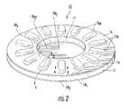
- FIG. 2is an enlarged perspective view of an assembled blister package according to embodiments of the present invention.
- FIG. 3is a greatly enlarged section view of a portion of the blister package taken along line 3 - 3 as shown in FIG. 2 .
- FIG. 4Ais an enlarged side sectional view of a portion of a blister package taken along line 4 - 4 of FIG. 2 , illustrating a blister according to embodiments of the present invention.
- FIG. 4Bis an enlarged side sectional view of a portion of a blister package taken along line 4 - 4 of FIG. 2 , illustrating a blister according to other embodiments of the present invention.
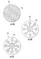
- FIG. 5Ais an exploded view of another blister package according to embodiments of the present invention.
- FIG. 5Bis a perspective view of the blister package shown in FIG. 5A assembled.
- FIG. 5Cis an enlarged side sectional view of a portion of the blister package shown line 5 C- 5 C in FIG. 5B illustrating a blister according to embodiments of the present invention.
- FIG. 6is a perspective view of a blister package assembly according to embodiments of the present invention.
- FIGS. 7A-7Care perspective views of alternative blister packages suitable for concurrent dispensing of a plurality of separately held medicaments or dry powders according to embodiments of the present invention.
- FIG. 8Ais a top or bottom view of an exemplary piezoelectric film layer according to embodiments of the present invention.
- FIGS. 8B and 8Care top or bottom views of examples of a primary surface opposing of the surface shown in FIG. 8A according to embodiments of the present invention.
- FIG. 8Dis a top or bottom view of an alternative conductive pattern layer according to embodiments of the present invention.
- FIG. 8Eis a top or bottom view of yet another conductive pattern layer according to embodiments of the present invention.
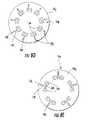
- FIG. 9is a top perspective view of a blister package according to additional embodiments of the present invention.
- FIG. 10is a top perspective view of yet another blister package similar to that shown in FIG. 9 , but without the gear component, according to embodiments of the present invention.
- FIG. 11is an exploded view of components that may be used to form the blister package shown in FIG. 9 or 10 according to embodiments of the present invention.
- FIGS. 12A and 12Bare enlarged partial side section views of a blister package such as those shown along line 12 - 12 in FIG. 10 illustrating exemplary blister configurations according to embodiments of the present invention.
- FIG. 13is a block diagram of a control system with computer program code that may be included on a blister package and/or communicate with an inhaler according to embodiments of the present invention.
- FIG. 14is a block diagram of a control system and/or data processing system according to embodiments of the present invention.
- FIG. 15is a flow chart of operations that can be carried out to fabricate a blister package according to embodiments of the present invention.
- FIG. 16is a flow chart of operations that can be carried out to fabricate a blister package according to other embodiments of the present invention.
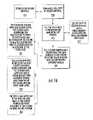
- FIG. 17Ais a flow chart of operations that can be carried out to fabricate a blister package according to further embodiments of the present invention.
- FIGS. 17B-17Dillustrate a serial progression of configurations of a blister package during the fabrication operations shown in FIG. 17A .
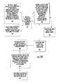
- FIG. 18is a flow chart of operations that can be used to form a floor of a blister package according to embodiments of the present invention.
- FIG. 19Ais a flow chart of operations that can be carried out to fabricate a laminated floor of a blister package according to embodiments of the present invention.
- FIGS. 19B-19Eillustrate a serial progression of configurations of piezoelectric floors suitable for a blister package during the fabrication operations shown in FIG. 19A .
- the term “front” or “forward” and derivatives thereofrefer to the general or primary direction that the dry powder travels as it is dispensed to a patient from a dry powder inhaler; this term is intended to be synonymous with the term “downstream,” which is often used in manufacturing or material flow environments to indicate that certain material traveling or being acted upon is farther along in that process than other material.
- the terms “rearward” and “upstream” and derivatives thereofrefer to the direction opposite, respectively, the forward or downstream direction.
- the spatially relative termsare intended to encompass different orientations of the device in use or operation in addition to the orientation depicted in the figures. For example, if a blister package shown in the figures oriented upward is inverted (turned over), elements described as “below” or “beneath” other elements or features would then be oriented “above” the other elements or features. Thus, the exemplary term “below” can encompass both an orientation of above and below.
- the devicemay be otherwise oriented (rotated 90 degrees, 180 degrees, or at other orientations) and the spatially relative descriptors (such as, but not limited to, vertical, horizontal, above, upper, lower, below and the like) used herein interpreted accordingly.
- blistermeans a sealed dry powder well or receptacle that can hold a (typically meted bolus) quantity of a dry powder, typically a dry powder medicament.
- blister packagedescribes a device (such as a card) that holds a plurality of sealed blisters and may be also known as a drug containment system (“DCS”).
- DCSdrug containment system
- the blistersmay be configured with a projecting ceiling as will be described further below, or configured in other suitable geometries.
- the devices and methods of the present inventionmay be particularly suitable for holding doses of dry powder substances that are formulated for in vivo inhalant dispersion (using an inhaler) to subjects, including, but not limited to, animal and, typically, human subjects.
- the dry powder substancemay include one or more active pharmaceutical constituents as well as biocompatible additives that form the desired formulation or blend.
- dry powderis used interchangeably with “dry powder formulation” and means the dry powder can comprise one or a plurality of constituents or ingredients with one or a plurality of (average) particulate size ranges.
- the term “low-density” dry powdermeans dry powders having a density of about 0.8 g/cm 3 or less. In particular embodiments, the low-density powder may have a density of about 0.5 g/cm 3 or less.
- the dry powdermay be a dry powder with cohesive or agglomeration tendencies.
- individual dispensable quantities of dry powder formulationscan be a single ingredient or a plurality of ingredients, whether active or inactive.
- the inactive ingredientscan include additives added to enhance flowability or to facilitate aeorolization delivery to the desired systemic target.
- the dry powder drug formulationscan include active particulate sizes that vary.
- the devicemay be particularly suitable for dry powder formulations having particulates which are in the range of between about 0.5-50 ⁇ m, typically in the range of between about 0.5 ⁇ m-20.0 ⁇ m, and more typically in the range of between about 0.5 ⁇ m-8.0 ⁇ m.
- the dry powder formulationcan also include flow-enhancing ingredients, which typically have particulate sizes that may be larger than the active ingredient particulate sizes.
- the flow-enhancing ingredientscan include excipients having particulate sizes on the order of about 50-100 ⁇ m.
- excipientsinclude lactose and trehalose.
- Other types of excipientscan also be employed, such as, but not limited to, sugars which are approved by the United States Food and Drug Administration (“FDA”) as cryoprotectants (e.g., mannitol) or as solubility enhancers (e.g., cyclodextrine) or other generally recognized as safe (“GRAS”) excipients.
- FDAUnited States Food and Drug Administration
- cryoprotectantse.g., mannitol
- solubility enhancerse.g., cyclodextrine
- GRASgenerally recognized as safe
- diseases, conditions or disordersthat may be treated with embodiments of the invention include, but are not limited to, asthma, COPD (chronic obstructive pulmonary disease), viral or bacterial infections, influenza, allergies, and other respiratory ailments as well as diabetes and other insulin resistance disorders.
- the dry powder inhalationmay be used to deliver locally acting agents such as antimicrobials, protease inhibitors, and nucleic acids/oligionucleotides as well as systemic agents such as peptides like leuprolide and proteins such as insulin.
- inhaler-based delivery of antimicrobial agentssuch as antitubercular compounds, proteins such as insulin for diabetes therapy or other insulin-resistance related disorders, peptides such as leuprolide acetate for treatment of prostate cancer and/or endometriosis and nucleic acids or ogligonucleotides for cystic fibrosis gene therapy may be performed.
- antimicrobial agentssuch as antitubercular compounds, proteins such as insulin for diabetes therapy or other insulin-resistance related disorders, peptides such as leuprolide acetate for treatment of prostate cancer and/or endometriosis and nucleic acids or ogligonucleotides for cystic fibrosis gene therapy
- antimicrobial agentssuch as antitubercular compounds
- proteinssuch as insulin for diabetes therapy or other insulin-resistance related disorders
- peptidessuch as leuprolide acetate for treatment of prostate cancer and/or endometriosis and nucleic acids or ogligonucleotides for cystic
- Typical dose amounts of the unitized dry powder mixture dispersed in the inhalerwill vary depending on the patient size, the systemic target, and the particular drug.
- Conventional exemplary dry powder dose amount for an average adultis about 10-30 mg and for an average adolescent pediatric subject is from about 5-10 mg.
- a typical dose concentrationmay be between about 1-2%.
- Exemplary dry powder drugsinclude, but are not limited to, albuterol, fluticasone, beclamethasone, cromolyn, terbutaline, fenoterol, ⁇ -agonists (including long-acting ⁇ -agonists), salmeterol, formoterol, cortico-steroids and glucocorticoids.
- the administered bolus or dosecan be formulated with an increase in concentration (an increased percentage of active constituents) over conventional blends.
- the dry powder formulationsmay be configured as a smaller administerable dose compared to the conventional 10-25 mg doses.
- each administerable dry powder dosemay be on the order of less than about 60-70% of that of conventional doses.
- the adult dosemay be reduced to under about 15 mg, such as between about 10 ⁇ g-10 mg, and more typically between about 50 ⁇ g-10 mg.
- the active constituent(s) concentrationmay be between about 5-10%.
- active constituent concentrationscan be in the range of between about 10-20%, 20-25%, or even larger.
- target dose amountsmay be between about 12-100 ⁇ g.
- the dry powder in a particular dose receptaclemay be formulated in high concentrations of an active pharmaceutical constituent(s) substantially without additives (such as excipients).
- substantially without additivesmeans that the dry powder is in a substantially pure active formulation with only minimal amounts of other non-biopharmacological active ingredients.
- minimal amountsmeans that the non-active ingredients may be present, but are present in greatly reduced amounts, relative to the active ingredient(s), such that they comprise less than about 10%, and preferably less than about 5%, of the dispensed dry powder formulation, and, in certain embodiments, the non-active ingredients are present in only trace amounts.
- certain active elementsare integral to/included as part of a disposable (replaceable) blister package.
- the inhaler with the drug blister packagecan itself be disposable after dispensing the doses provided by a blister package. Unlike many conventional active dispersion systems, cleansing of the active mechanism portion of the inhaler may not be required. Examples of suitable inhalers are described in co-pending U.S. patent application Ser. No. 10/434,009 and Provisional U.S. Patent Application Ser. No. 60/514,671, the contents of these documents are hereby incorporated by reference as if recited in full herein.
- FIGS. 1A and 2illustrate one exemplary blister package 15 .
- the blister package 15includes a plurality of spaced apart blisters 15 b .
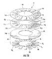
- the blister package 15can include a ceiling 16 with projections 16 p (i.e., wells) overlying each blister 15 b , an intermediate (a.k.a., “spacer”) member 17 and a floor 18 .
- the intermediate member 17can have a thickness that is greater than the combined thickness of the ceiling and floor 16 , 18 , respectively.
- the intermediate member 17will have a thickness that is at least five times, and typically at least about ten times, and more typically at least about 15 times, greater than the thickness of either the floor 18 or ceiling 16 .
- the ceiling 16may also be substantially planar over the apertures of the spacer member 17 (and/or over the entire surface of the spacer member 17 ).
- the ceiling 16is configured to be removed, when in position in an inhaler, to dispense the dry powder 100 held therein ( FIGS. 4A and 4B ).
- the ceiling 16can comprise a relatively thin flexible material.
- the ceiling 16comprises a flexible material layer that has sufficient structural rigidity so as to be able to have projections 16 p formed therein that retain their shape as shown in FIG. 1 when in position.
- the ceilingis typically configured to inhibit moisture penetration to keep the dry powder, dry, for the desired shelf and/or useful life of the dry powder (drug).
- the ceiling 16can contain foil (such as aluminum or other suitable material) and/or may be a laminated structure, comprising a polymer layer and a foil layer.
- the ceiling 16can comprise layers of polyamide film, aluminum foil, and polypropylene film (where the top layer may be the polyamide film) adhered to each other with a laminating adhesive.
- the ceiling 16can have a thickness of between about 0.100-0.150 mm, and typically about 0.127 mm.
- the projections 16 pmay have a height that is between about 1-5 mm and typically at least about 1.5 mm.
- the intermediate member 17includes a plurality of spaced apart gap spaces or apertures 17 a extending therethrough, each having a depth that defines at least a portion of a sidewall 17 w ( FIG. 3 ) of a blister 15 b .
- the intermediate member 17defines substantially the entire (typically all of the) sidewall 17 w of a respective blister 15 b (see, e.g., FIGS. 4A and 4B ) and extends a distance above the floor 18 and below the ceiling 16 .
- the gap space or aperture 17 acan include a single sidewall 17 w when the geometric shape of the aperture is circular, oval, curvilinear (such as elongate channel) or other continuous shape.
- the aperture 17 acan be configured with a plurality of contiguous sidewalls 17 w (i.e., a square, rectangle, triangle, wedge, or other multi-sided shape).
- FIG. 1Aillustrates the aperture 17 a having an elongate curvilinear configuration (when viewed from the top and/or bottom).
- FIGS. 5A-5Cillustrate a blister package 15 with a ceiling 16 having semi-spherical projections 16 p and an intermediate member 17 having a substantially circular aperture 17 a (when viewed from the top and/or bottom).
- the sidewall 17 w of the blister 15 bcan angle or taper inward from top to bottom, with the surface area of the bottom of the aperture 17 a being less than that of the top of the intermediate member aperture 17 a .
- the sidewall 17 wcan have an angle of inclination (that may be substantially constant) that is between about 15-60 degrees, and typically between about 20-40 degrees.
- the sealed blister 15 bis illustrated as enclosing a quantity of dry powder 100 therein.
- the frame apertures 17 ahave a perimeter shape 17 p .
- the perimeter shape 17 pis sized and configured to substantially correspond with the perimeter shape 15 p of the blister 15 b that is defined by that of the projecting ceiling 16 p .
- the aperture 17 amay have a shape and size that is substantially the same as the shape and size of a respective projecting overlying ceiling 16 p.
- the intermediate member 17can have increased rigidity with respect to that of the floor 18 and/or ceiling 16 .
- the intermediate member 17can be a substantially rigid light-weight member that provides structural integrity to the ceiling and floor 16 , 18 .
- the ceiling 16can be attached to an upper primary surface 17 u of the intermediate member 17 and the floor 18 can be attached to a lower primary surface 17 b of the intermediate member 17 .
- the intermediate member 17may have a unitary body as shown or a laminated or stacked structure (not shown).
- the intermediate member 17can be a molded polymer or fiber reinforced resin material.
- the intermediate member 17comprises a natural homopolymer polypropylene and can typically be between about 1-3 mm thick, and is more typically about 2 mm thick.
- the intermediate member 17may include additional apertures, slots or depressions and the like to further decrease weight as suitable.
- the intermediate member 17may be configured with sufficient thickness, material and/or coatings to provide a moisture barrier (inhibit moisture penetration) to the dry powder held in the blister as discussed above for the ceiling.
- the ceiling and floor 16 , 18can comprise a continuous sheet(s) or layer(s) of material as shown in FIGS. 1A , 1 B and 5 A.
- the ceiling and/or floor 16 , 18may comprise non-continuous discrete segments of material forming a respective blister ceiling 16 and floor 18 that can be attached over and under each intermediate member aperture 17 a to define respective sealed blisters 15 b (not shown).
- FIGS. 1A and 1Billustrate that the floor 18 can include a plurality of abutting flexible and/or resilient layers 18 i , shown as two different layers, a non-active layer 18 1 and an active layer 18 2 .
- the active layer 18 2may be positioned above the non-active layer 18 1 .
- the term “active” layermeans that the layer comprises an electrically active material.
- the active layer 18 2comprises a thin-film layer of a piezoelectric material, typically a polymer such as PVDF as will be described further below.
- additional floor layersmay also be used (not shown).
- the floor 18can be a single layer configuration defined by the active layer 18 2 (also not shown).
- the floor 18can be configured to inhibit moisture penetration (i.e., be configured to provide a moisture barrier at operating/exposure pressures for a desired length of time) into the blister space thereby keeping the dry powder dry and ready for flowable dispersion via inhalation.
- the portions of the floor 18i.e., such as the upper surface
- the portions of the floor 18should be configured to be compatible therewith (i.e., chemically and/or physically).
- the floor layers 18 iare attached to each other so that flexure (up and down) of one layer causes the other(s) to substantially concurrently flex up and down in response thereto.
- the floor layers 18 ican be configured so that the flexing of the active layer 18 2 is not substantially reduced or insulated by the other contacting layer (s) to thereby provide a desired vibratory dispersion input to the dry powder 100 in a blister 15 b during active inspiration.
- the floor layers 18 1 , 18 2can be a laminated structure or otherwise attached over a sufficient surface area to facilitate substantially concurrent flexing at a floor 18 of a respective blister 15 b to thereby vibrate dry powder held therein during operation.
- the non-active portion or layers of the floor 18may include material(s) similar to that described for the ceiling 16 above.
- the floor layers 18 1 , 18 2may be adhesively attached, heat and/or pressure bonded, or otherwise attached.
- the non-active layer 18 1can include foil, typically aluminum foil, and may, in certain embodiments, include a polymer coating or layer on the top and/or bottom thereof. Typically the non-active portion of the floor 18 1 will be at least about 20 microns thick. Coatings and/or other materials can be used to inhibit moisture penetration (i.e., act as a moisture barrier) into the sealed blister cavity and/or to aid in sealing (i.e., adhering) the floor 18 to adjacent structures or layers.
- One suitable materialis available from Hueck Foils, located in Blythewood, S.C.
- the non-active layer 18 1may be attached using a relatively thin foil-release material such as a release film.
- the release filmcan be used to transfer a pressure sensitive adhesive (PSA) to a desired layer (such as shown in FIG. 19C ) that can be used to attach two layers together.
- PSApressure sensitive adhesive
- the upper surface 18 u of the non-active layer 18 2may define the dry powder contact surface of the blister 15 b as shown in FIG. 3 and can be attached to the active layer 18 2 that can comprise the piezoelectrically active material.
- the active layer 18 2can be configured with a predetermined conductive pattern 18 p .
- the pattern 18 pcan include a plurality of spaced apart segments 18 s sized, configured and aligned to be positioned under a bottom of each blister 15 b .
- the pattern 18 pcan also include at least one electrical (signal) trace 18 t leading from the segment 18 s to an electrical contact zone 18 z .
- the electrical contact zone 18 zis shown as centrally positioned on the active layer 18 2 ; however, other electrical contact zone configurations and locations can be used. In those embodiments, alternative access through, on or around the intermediate member 17 may be provided.
- the intermediate member 17may be molded or formed into other shapes without a center aperture and/or different access configurations.
- FIGS. 8D and 8Eillustrate conductive patterns 18 p ′ with contact zones 18 z located proximate an outer perimeter of the blister package.
- FIG. 8Dillustrates that each blister may have its own contact zone for individual selective activation (individually addressable blisters) or excitation of a target blister in operation.
- FIG. 8Eillustrates a different blister shape and also that respective pairs of blisters may share a common contact zone 18 z with traces 18 t for each blister traveling toward each other and merging to the common contact zone 18 t .
- Other numbers of blisterscan be electrically grouped and/or the contact zones may be positioned at other locations.
- the plurality of shared contact zones 18 zone for each pair of blisters, may be particularly suitable for use in combinatorial dispersion configurations, such as those shown in FIGS. 7A-7C .
- a predetermined electrical signalcan be applied to the active layer 18 2 to flex the floor of the blister 15 b and vibrate the powder 100 held therein ( FIGS. 4A , 4 B).
- the electrical signalis transmitted to the blister 15 b in a dispensing location via the conductive pattern 18 p (such as via the conductive zone 18 z to the trace 18 t and the segment 18 s under the blister 15 b ).
- a plurality of blisters 15 bmay be in electrical communication with a signal generator 200 ( FIG. 13 ) and concurrently flexed.
- the predetermined pattern 18 pcan be configured so that a selective blister 15 b can be flexed (not shown).
- the contact zone 18 zmay be configured as a discrete contact zone for each blister 15 b .
- a regional contact zone 18 zmay also be provided to electrically communicate with a plurality of blisters (not shown). Electrical insulation or discontinuous conductive patterns 18 p can be used to provide electrical separation as is well known to one of skill in the art.
- the contact zone 18 zmay be otherwise located, such as at an outer or inner edge of the pattern 18 p to communicate with the signal generator 200 .
- the signal generator 200(such as that shown in FIG. 13 ) may be integrated with the blister package 15 b or held in the inhaler so as to engage the active floor layer 18 2 in operation.
- the predetermined pattern 18 pcan comprise a conductive material such as metal.
- the conductive materialcan be a thin layer of metal or other conductive material that can be inked, stamped, printed (including screen printed), imaged (including, but not limited to, photo-resist imaging), rolled, deposited, sprayed, or otherwise applied to (one or both primary surfaces of) the active layer 18 2 .
- Other methods of providing the conductive pattern 18 pcan also be used, including electron beam evaporation, thermal evaporation, painting, dipping, or sputtering a conductive material or metallic paint and the like or material over the selected surfaces of the piezoelectric substrate (preferably a PVDF layer as noted above).
- alternative metallic circuits, foils, surfaces, or techniquescan also be employed, such as attaching a conductive mylar layer or flex circuit over the desired portion of the outer surface of the piezoelectric substrate layer. If flex circuits are used, they may be configured or attached to the piezoelectric substrate layer so as to be substantially transparent to the structure to reduce any potential dampening interference with the substrate layer.
- upper and lower surface metal trace patternsare formed on opposing sides of a piezoelectric polymer material layer but do not connect or contact each other.
- conductive paint or inksuch as silver or gold
- This configurationforms the electrical excitation path when connected to a control system to provide the input/excitation signal for creating the electrical field that activates the deformation of the piezoelectric substrate layer during operation.
- one pattern 18 pis applied to one side of the active floor 18 2 and the other side may have a different conductive pattern and/or coverage.
- FIG. 1Aillustrates that the active layer 18 2 may have a different configuration that the first floor layer 18 1 .
- FIGS. 1B and 8Aillustrate that the first floor layer 18 1 , the intermediate member 17 and the ceiling 16 may be configured with substantially the same shape and size (shown as substantially circular) when viewed from the top, and have aligned center spaces or apertures 16 c , 17 c , 18 1 c, that when assembled provide an access window 15 w that exposes a center portion 18 2 c ( FIG. 2 , 3 , 5 B) of the top surface of the second or active floor layer 18 2 . Where edge contact zones or other electrical contact configurations are used, the center window 15 w to the active layer 18 2 may not be used.
- FIG. 5Cillustrates that the active floor layer 18 2 can be substantially coextensive at least about an outer perimeter portion of the blister package 15 while FIGS. 4A and 4B illustrate that the active floor layer 18 2 can be discontinuous at the outer perimeter portion of the blister package 15 .
- FIGS. 4B and 5Calso illustrate that the floor 18 of a respective blister 15 b can be substantially planar about the intermediate member gap space or aperture 17 a while FIG. 4A illustrates that the floor 18 may be configured with a recession 18 r therein (formed by at least the first layer 18 , and in some instances a depression in the piezoactive layer 18 2 conformally thereunder (not shown)).
- FIG. 1Aillustrates that the active layer 18 2 may cover or have less surface area than the first floor layer 18 1 , of the blister package 15 .
- FIG. 1Billustrates that the first and second floor layers 18 1 , 18 2 can be substantially coextensive with each other (at least over a major portion of the configurations thereof away from the center portions) with the first layer 18 1 , having an aperture 18 1 c that exposes or provides electrical contact with the underlying active layer 18 2 . It is noted that FIG. 1B is shown without a full conductive pattern 18 p .
- the active layer 18 2can be a continuous layer of film that is substantially circular. Other configurations may be used.
- one of the primary surfaces of the active layer 18 2may have a first predetermined conductive pattern 18 p 1 as shown in FIGS. 8C and 8D while the other surface can have a different second predetermined conductive pattern 18 p 2 as shown in FIG. 8A .
- the second conductive pattern 18 p 2 shown in FIG. 8Aillustrates that substantially the entire primary surface can be conductive (i.e., metallized).
- the first predetermined pattern 18 p 1may be oriented to be the upper surface configured to contact the underside of the first floor layer 18 1 , (or the intermediate member 17 , where the active layer defines the floor of a blister) with the second pattern 18 p 2 oriented away from the first floor layer 18 1 .
- the reverse orientationmay be used in other embodiments.
- the second layer 18 2may used without the first layer 18 1 , so as to define the floor of the blister 15 b.
- the active layer 18 2includes a piezoelectric polymer material that can be formed from a piezoelectrically active material such as PVDF (known as KYNAR piezo film or polyvinylidene fluoride) and its copolymers or polyvinylidene difluoride and its copolymers (such as PVDF with its copolymer trifluoroethylene (PVDF-TrFe)).
- PVDFpiezoelectrically active material
- PVDFknown as KYNAR piezo film or polyvinylidene fluoride
- PVDF-TrFepolyvinylidene difluoride
- the piezoelectric polymer materialcomprises a layer of a thin PVDF film.
- the term “thin film”means that the piezoelectric polymer layer is configured as a structurally flexible or pliable layer that can be sized to be about 10-200 ⁇ m thick. In certain embodiments, the piezoelectric polymer layer can be sized to be less than about 100 ⁇ m thick, typically about 20-60 ⁇ m thick, and more typically about 28 ⁇ m.
- selected regions of the piezoelectric polymer materialcan be coated or layered with a conductive material to form a desired conductive pattern 18 p .
- the conductive regions (at least portions of the blister regions) of the floor 18define the active regions and can be individually or selectively activated during operation.
- the PVDFmay form the bottom, top, or an intermediate layer of the laminated material structure.
- vias and/or edge connectionscan be used to apply the electric signal to the blister piezoelectric material.
- the excitation circuit (signal generating circuitry) configurationcan be such that the one surface operates with a positive polarity while the other surface has a negative polarity or ground, or vice versa (thereby providing the electric field/voltage differential to excite the piezoelectric substrate in the region of the selected blister 15 b ).
- the polaritiescan also be rapidly reversed during application of the excitation signal (such as + to ⁇ , or + to ⁇ ) depending on the type of excitation signal used, thereby flexing the piezoelectric material in the region of the receptacle portion.
- FIG. 6illustrates that a mounting member 50 may be attached to the blister package 15 .
- the mounting member 50can be configured to engage an inhaler to hold the blister package 15 in position therein while allowing the blister package 15 to rotate to present a blister 15 b for dispensing via the inhaler.
- the mounting member 50may be integrally mounted or formed onto the blister package 15 (by, for example, bonding or molding to the body of the intermediate member 17 ).
- the mounting member 50may be sized and configured to reside over (within and/or above) the blister window 15 w .
- the mounting member 50may use tabs 52 or other mechanisms to attach to the blister package 15 so that the blister package 15 rotates with the mounting member 50 when in position in the inhaler.
- FIG. 1illustrates that a mounting member 50 may be attached to the blister package 15 .
- the mounting member 50can include electrical leads or traces that extend from the signal generator 200 to the active floor layer 18 2 .
- the gear 50 gcan include a bore 50 b therein which can be configured to allow access to an exposed surface of the active layer 18 2 .
- the mounting member 50can be configured as a rotatable gear 50 g with gear teeth 50 t ( FIG. 9 ) that mounts in the inhaler.
- a pawl or other indexing mechanismcontacts one or more gear teeth 50 t to so as to controllably rotate the gear 50 g and thereby advance the blister package 15 therewith to position a blister 15 b at a blister dispensing location in the inhaler.
- FIGS. 7A-7Cillustrate alternative configurations of the intermediate member 17 with closely spaced neighboring intermediate member apertures 17 a 1 , 17 a 2 that define a sidewall(s) of corresponding blisters 15 b 1 , 15 b 2 (not shown) which can be used to concurrently dispense the dry powder in neighboring blisters for combination therapeutic treatments.
- the neighboring apertures 17 a 1 , 17 a 2(which may be pairs or sets of three of more apertures) may be spaced closer together on the intermediate member 17 than the non-neighboring apertures.
- Each adjacent or neighboring blister 15 b 1 , 15 b 2may contain different medicaments and/or dry powders therein that can be concurrently released upon inhalation during operative use.
- FIG. 7Aillustrates side by side, neighboring (adjacent) pairs of apertures 17 a 1 , 17 a 2 that form the sidewall(s) of corresponding blisters 15 b 1 , 15 b 2 (not shown) that are configured to be jointly dispersed upon inhalation in an inhaler.
- FIG. 7Billustrates front to back neighboring blister sidewalls 17 a 1 , 17 a 2 that can also configured to be jointly dispersed upon inhalation via an inhaler.
- FIG. 7Cillustrates yet another side-by-side configuration with neighboring elongate apertures 17 a 1 , 17 a 2 .
- the side-by-side aperture/blister configurationsmay be offset lengthwise (not shown) across the blister package.
- FIGS. 9-12Billustrate an alternative embodiment of a blister package 15 ′.
- the blister package 15 ′includes the ceiling 16 that has a body that resides below a frame 117 .
- the frame 117overlies the ceiling 16 and includes a plurality of apertures 117 a that are sized and configured to allow the blister ceiling projections 16 p to extend therethrough.
- the frame 117can be configured to resist flexure and/or have increased rigidity relative to the floor 18 and/or ceiling 16 of the blister package.
- the frame 117can have a thickness that is greater than the combined thickness of the ceiling 16 and floor 18 .
- the frame 117can have a molded body comprising a polymer material.
- the frame 117may be between about 0.25-2 mm thick, and typically between about 0.5-1 mm thick. In certain embodiments, the frame 117 may be substantially rigid. The frame 117 can have a substantially planar top and bottom surface 117 t , 117 b ( FIG. 11 ).
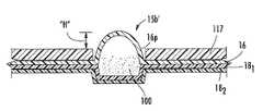
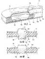
- the ceiling projections 16 pare configured to rise above the top surface 117 t of the frame 117 a desired distance. As shown in FIGS. 12A and 12B , the ceiling projection 16 p may rise a distance “H” above the frame 117 between about 1-10 mm, typically at least about 2 mm. As shown, the blister 15 b is formed by the sealing of the floor 18 with the ceiling 16 (the frame 117 does not form the sidewalls of the blister). The floor 18 of the blister 15 may be recessed as shown in FIG. 12B or substantially planar such as shown in FIG. 12A .
- FIG. 11illustrates that the floor 18 may include a plurality of flexible layers, shown as two floor layers, 18 1 , 18 2 , as discussed above.
- FIG. 9illustrates that the blister package 15 ′ may include a mounting member 50 ′ thereon.
- the mounting member 50 ′can include a gear 50 g with gear teeth 50 t that engage an indexing mechanism in the inhaler as discussed above.
- the mounting member 50 ′may be integrally attached to, formed on, or releasably attached to the frame 117 to form a blister package 15 ′.
- the blister package 15 ′is not required to include a mounting member.
- the gear 50 gcan include a bore 50 b therein which can be configured to allow access to an exposed surface of the active layer 18 2 .
- the inhalermay include a pin that engages the bore of the gear to hold the gear and blister package in position and allow the gear 50 g to rotate in the inhaler.
- the blister frame 117 and blister package 15 ′may be configured as a replaceable modular unit for an inhaler.
- the blister frame 117 , the gear 50 g and the blister package 15 ′are a modular unit that is disposable after the blisters have been depleted and the inhaler is configured to allow replacement thereof.
- the blister package 15may be configured to have a substantially disk-like shape.
- the blister package 15 , 15 ′can be configured to rotate in the inhaler to advance a respective blister into an indexed or registered inhalation position.
- the frame 117can include a plurality of frame apertures 117 a , each with a perimeter shape 117 p .
- the perimeter shape 117 pis sized and configured to allow the projecting ceiling 16 p of the blister 15 b to extend therethrough.
- the frame aperture perimeter shape 117 pmay be configured to substantially correspond to the blister perimeter shape 15 p when viewed from the top.
- the frame aperture 117 amay have a shape and size that is substantially the same as the shape and size of a respective blister 15 b .
- the blister 15 bcan have a width and length and the aperture 117 a can have substantially the same width and length (typically just a bit larger than the width/length of the blister).
- the blister package 15 , 15 ′can include visible indicia and/or can be configured to engage an inhaler to provide audible alerts to warn a user that he/she is approaching the last of the filled blister inhalant doses on the blister package 15 , 15 ′ and/or to indicate that the dose was properly (and/or improperly) inhaled or released from the inhaler device.
- certain dry powder dose sizesare formulated so that it can be difficult for a user to know whether they have inhaled the medicament (typically the dose is aerosolized and enters the body with little or no taste and/or tactile feel for confirmation).
- a sensorcan be positioned in communication with a blister 15 b in a dispensing position in an inhaler and configured to be in communication with a digital signal processor or microcontroller, each held in or on the inhaler and/or the blister package 15 , 15 ′.
- the sensoris configured to detect a selected parameter, such as a difference in weight, a density in the exiting aerosol formulation, and the like, to confirm that the dose was released.
- the blister package 15 , 15 ′can include color-enhanced markings for the last few (such as the last 5) doses.
- the color-enhanced markingsmay change from darker (orange to salmon or red) or to completely different colors as the last dose or last few doses approach.
- the multi-dose disposable package 15 , 15 ′may be configured with audible alert features that activate a digital signal processor or micro-controller (not shown) housed in the inhaler to generate a stored audible verbal message or warning (such as “warning, refill needed, only five doses remain”) when a desired number of doses have been administered.
- a forward or leading (cutting) edge portion of a bladein position, can be configured to open (typically cut or slice) at least a portion of the projecting ceiling 16 p of a blister 15 b , 15 b ′ by traveling generally (typically substantially) parallel to a plane extending horizontally about an upper portion of an underlying blister along a length direction thereof at a position that is less than the height of the blister projection, to slice a major portion of the ceiling in the length direction, forming a gap space to allow the dry powder held in the blister 15 b , 15 b ′ to be dispensed.
- FIG. 13illustrates an example of a signal generator 200 that may be configured to reside in and/or communicate with the blister package 15 , 15 ′.
- the signal generatorcan include a processor (such as a digital signal processor) 215 and electronic memory 222 .
- the electronic memorycan include, but is not limited to, cache, ROM, PROM, EPROM, EEPROM, flash memory, SRAM, and DRAM.
- the signal generator 200may, in certain embodiments, also include a powder specific non-linear signal generator computer program module 220 that provides the electrical signal characteristics for the drug being dispensed.
- the module 220may be programmed into the memory 222 .
- the signal generator 200may have a sleep or inactive (or off) mode that is turned to an active mode based on inhaler activation via input from a switch or a sensor 223 .
- the signal generator 200may communicate with a power source 10 such as a battery (typically a miniaturized battery, such as a digital camera or pancake type flat battery) to power the signal generator and transmit the electrical signal to the desired blister 15 b , 15 b ′.
- the activationmay be carried out automatically based upon input from a sensor and/or activation from an “on” switch.
- the vibratory signalcan include a kHz carrier frequency (such as about 5 kHz-50 kHz) modified by low modulating frequency (typically about 10-200 Hz).
- the frequency of the vibrationcan be modified to match or correspond to the flow characteristics of the dry powder substance held in the package to attempt to reach a resonant frequency(s) to promote uniform drug dispersion into the body.
- a non-linear powder-specific dry powder vibratory energy signala different powder specific signal for each of the formulations on a blister package or the same for a particular formulation on each package) comprising a plurality of selected frequencies can be generated (corresponding to the particular dry powder being currently dispensed) to output the particular signal corresponding to the dry powder then being dispensed.
- non-linearmeans that the vibratory action or signal applied to the package to deliver a dose of dry powder to a user has an irregular shape or cycle, typically employing multiple superimposed frequencies, and/or a vibratory frequency line shape that has varying amplitudes (peaks) and peak widths over typical standard intervals (per second, minute, etc.) over time.
- the non-linear vibratory signal inputcan operate without a fixed single or steady state repeating amplitude at a fixed frequency or cycle.
- This non-linear vibratory inputcan be applied to the blister to generate a variable amplitude motion (in either a one, two and/or three-dimensional vibratory motion).
- the non-linear signalfluidizes the powder in such a way that a powder “flow resonance” is generated allowing active flowable dispensing.
- the blister package 15 , 15 ′can include signal-generating circuitry and/or components held thereon or therein which, in operation, are in communication with the blisters 15 b , 15 b ′ (via the conductive pattern 18 p on the active floor 18 2 ).
- the signal generating circuitrymay be programmed with a plurality of predetermined different input signals, or if the blister package dispenses only a single dry powder, the signal generator may be programmed with a single signal.
- Appropriate powder-specific signalscan be determined experimentally and/or computationally at an OEM or evaluation site and input into the inhalers (via hardware and/or software components including programmable processors). For additional description of signals and operations to determine same, see co-pending and co-assigned U.S.
- a signal of combined frequenciescan be generated to provide a non-linear signal to improve fluidic flow performance.
- Selected frequenciescan be superimposed to generate a single superposition signal (that may also include weighted amplitudes for certain of the selected frequencies or adjustments of relative amplitudes according to the observed frequency distribution).
- the vibratory signalcan be a derived non-linear oscillatory or vibratory energy signal used to dispense a particular dry powder.
- the output signal used to activate the piezoelectric blister channelmay be include a plurality (typically at least three) superpositioned modulating frequencies and a selected carrier frequency.
- the modulating frequenciescan be in the range noted herein (typically between about 10-500 Hz), and, in certain embodiments may include at least three, and typically about four, superpositioned modulating frequencies in the range of between about 10-100 Hz, and more typically, four superpositioned modulating frequencies in the range of between about 10-15 Hz.
- the blister packages 15 , 15 ′are configured to operate with dry powder inhalers.
- the inhalerscan be used for nasal and/or oral (mouth) respiratory delivery.
- the inhalable dry powder dosescan be packaged in multi-dose dry powder drug packages that may include a piezoelectric polymer substrate (such as PVDF) that flexes to deform rapidly and provide mechanical oscillation in an individually selectable signal path on the package.
- the signal pathdirects the signal to the region of the drug receptacle or well to cause the well to oscillate in cooperation with a user's inspiratory effort, and, thus, actively direct the dry powder out of the well and up into the exit flow path.
- FIG. 14is a block diagram of exemplary embodiments of data processing systems that illustrate an example of a computer program product module 220 of FIG. 13 in accordance with embodiments of the present invention.
- the module 220may be configured to provide powder specific or other types of electrical signal input signals.
- the processor 410communicates with the memory 414 via an address/data bus 448 .
- the processor 410can be any commercially available or custom microprocessor.
- the memory 414is representative of the overall hierarchy of memory devices containing the software and data used to implement the functionality of the data processing system 405 .
- the memory 414can include, but is not limited to, the following types of devices: cache, ROM, PROM, EPROM, EEPROM, flash memory, SRAM, and DRAM.
- the memory 414may include several categories of software and data used in the data processing system 405 : the operating system 452 ; the application programs 454 ; the input/output (I/O) device drivers 458 ; a powder (specific) signal generator (vibratory) module 220 ; and the data 456 .
- the data 456may include: (a) a look-up chart/table data for dry powder signal formulations for plurality of different dry powders 451 ; (b) in situ acquired measurement data whether to confirm that the dry powder dose was properly (or improperly) dispensed and/or patient inspiratory data, which may be obtained from an operator or stored by the inhaler; (c) and/or timing data that automatically activates the signal and inputs to the blister for dispensing the dry powder based upon a pull operation (pulling the cutting cartridge and/or mouthpiece outward).
- the operating system 452 of the inhaler, blister package 15 , 15 ′ and/or programmable inputs theretomay be any operating system suitable for use with a data processing system, such as OS/2, AIX, OS/390 or System390 from International Business Machines Corporation, Armonk, N.Y., Windows CE, Windows NT, Windows95, Windows98 or Windows2000 from Microsoft Corporation, Redmond, Wash., Unix or Linux or FreeBSD, Palm OS from Palm, Inc., Mac OS from Apple Computer, LabView, or proprietary operating systems.
- the I/O device drivers 458typically include software routines accessed through the operating system 452 by the application programs 454 to communicate with devices such as I/O data port(s), data storage 456 and certain memory 414 components and/or the dispensing system 420 .
- the application programs 454are illustrative of the programs that implement the various features of the data processing system 405 and preferably include at least one application which supports operations according to embodiments of the present invention.
- the data 456represents the static and dynamic data used by the application programs 454 , the operating system 452 , the I/O device drivers 458 , and other software programs that may reside in the memory 414 .
- the present inventionis illustrated, for example, with reference to the powder signal generator module 220 being an application program in FIG. 14 , as will be appreciated by those of skill in the art, other configurations may also be utilized while still benefiting from the teachings of the present invention.
- the module 220may also be incorporated into the operating system 452 , the I/O device drivers 458 or other such logical division of the data processing system 405 .
- the present inventionshould not be construed as limited to the configuration of FIG. 14 , which is intended to encompass any configuration capable of carrying out the operations described herein.
- the I/O data portcan be used to transfer information between the data processing system 405 and the inhaler dispensing system 420 or another computer system or a network (e.g., the Internet) or to other devices controlled by the processor.
- These componentsmay be conventional components such as those used in many conventional data processing systems which may be configured in accordance with the present invention to operate as described herein.
- FIG. 15illustrates an example of operations that can be carried out to fabricate a blister package 15 such as that shown in FIGS. 1A , 1 B, 5 A, 6 , and 7 A- 7 C according to embodiments of the present invention.
- Wellsi.e., projections that are wells when the ceiling is inverted from the configuration shown certain of the figures such as in FIG. 1A
- the ceiling materialmay be a relatively thin laminated structure.
- the wellscan be filled with a predetermined amount of dry powder (block 305 ). The term “filled” includes providing an amount that is less than the volumetric capacity of the well.
- the ceiling materialmay be sterilized prior to (and/or after the wells are formed and/or prior to depositing the dry powder therein) (block 351 ).
- An intermediate member having a substantially rigid body with opposing upper and lower primary surfaces and a thickness with apertures extending therethroughcan be aligned with the ceiling so that a respective aperture aligns with a respective well (block 310 ).
- the intermediate member upper primary surfacecan be sealed to the ceiling material (block 315 ) and the opposing primary surface sealed to the floor comprising a piezoelectric material to define sealed blisters with the dry powder captured therein (block 320 ).
- the floorcan be sealed to the intermediate member after the intermediate member is aligned with and/or sealed to the ceiling (block 321 ).
- the floorcan be sealed to the intermediate member before the intermediate member is aligned with and/or sealed to the ceiling (block 322 ).
- the intermediate membercan be attached to the ceiling before the dry powder is positioned therein or after the dry powder is held therein. If the latter, the intermediate member is attached to the ceiling while the projections are facing down with the wells holding the dry powder. If the former, the ceiling can be a planar sheet (not requiring projections or wells) as the intermediate member can define a well sized to hold dry powder therein.
- the sheet of ceiling materialcan be cut into a predetermined shape after the dry powder is placed in the wells (block 307 ). If so, a sheet of a first floor layer can be used to seal the intermediate member and the first floor layer sheet cut concurrently with the ceiling material into a desired shape. In other embodiments, the ceiling material and floor can be separately formed into desired shapes prior to attachment. As described above, mounting and/or electrical components can be assembled to the blister package.
- FIG. 16illustrates operations that can be used to fabricate blister packages 15 b ′ (such as shown in FIGS. 9-12 ).
- wellscan be formed into the ceiling material (block 350 ).
- the wellscan be filled with a desired amount of dry powder (block 355 ).
- a floor comprising a piezoelectric polymer materialcan be sealed to the ceiling to define sealed blisters with the dry powder captured therein (block 360 ).
- the ceiling (and floor)can be sterilized (block 351 ).
- the floorcan include first and second layers, the second layer comprising the piezoelectric polymer.
- the first layercan be a flexible material (i.e., lid stock and/or foil release material) that can be sealed to the ceiling to seal the blisters with the dry powder held therebetween and then the second layer can be attached to the first floor layer (block 361 ).
- the sheet of ceiling materialcan be cut into a predetermined shape after the dry powder is placed in the wells (block 357 ).
- the first floor layercan be cut into substantially the same shape as the ceiling prior to and/or after attaching to the ceiling holding the dry powder (block 363 ). If the latter, a sheet of the first floor layer can be cut concurrently with the ceiling material into a desired shape.
- the ceiling and floor layercan have a disk-like shape with center apertures and the second floor layer can have a substantially circular body with a greater surface area than that of the ceiling and or first layer of the floor (block 362 ).
- the ceiling material and floorcan be separately formed into desired shapes prior to attachment. As described above, mounting and/or electrical components can be assembled to the blister package.
- FIG. 17Aillustrates operations that may be used to fabricate a primary blister package to which a piezoelectric material may be subsequently applied according to some embodiments of the present invention.
- blister wellscan be formed in a ceiling material sheet (block 370 ).
- FIG. 17Billustrates a ceiling sheet 16 sh with the sheet oriented with the projections 16 p down to define the wells 16 w .
- the wells 16 wcan be filled with dry powder (block 372 ).
- FIG. 17Cillustrates the dry powder 100 in the wells 16 w .
- the first floor layer of the floorwhich can comprise a foil, is heat sealed to the ceiling and the sealed structure cut into a desired shape (block 374 ) and FIG. 17D .
- the blister packagecan undergo a content uniformity assessment or inspection (block 376 ). If the blister package passes, the blister package can proceed to piezoelectric lamination operation (block 378 ). If the blister package fails, the package is rejected, the cause may be identified so that the process can be adjusted and/or corrective action taken as needed (block 379 ).
- FIG. 18illustrates exemplary operations for providing a suitable piezoelectric or active floor layer.
- a sheet of PVDFcan be obtained with a predetermined conductive pattern on a selected primary surface thereof (block 380 ).
- the predetermined conductive patterncan be formed on the selected primary surface (block 381 ) or pre-configured thereon.
- the PVDF layercan be attached to a flexible first floor layer (block 385 ). As noted above, the PVDF layer can be applied to the first layer after the first layer is sealed to the ceiling (or intermediate member) or before.
- the PVDF sheetcan be metallized (coated, formed, or otherwise deposited with a thin metal layer) that can substantially cover both primary surfaces (typically not the minor surfaces) and the conductive pattern formed by selectively removing a portion of the metal on the selected primary surface (block 383 ).
- the conductive patterncan be screen printed on the PVDF sheet (block 382 ).
- other conductive pattern formation techniquesmay also be used.
- the PVDF sheetcan be formed into a desired shape (block 384 ).
- the shapecan be formed prior to or after the formation of the conductive pattern.
- the shape of the PVDF floor layercan be substantially circular (and planar).
- the flexible floor layerscan be securely attached to define a flexible substantially laminated floor (block 386 ).
- the first floor layercan be attached after the first floor layer is sealed to the ceiling and/or intermediate member (block 387 ).
- the PVDF layermay be adhesively attached, heat and/or pressure bonded or otherwise attached.
- the conductive patternmay be oriented to face the first floor layer (block 388 ).
- FIG. 19Aillustrates operations to form a multi-layer flexible floor with PVDF according to some particular embodiments of the present invention.
- a disk or other desired shapecan be cut from PVDF material that has been metallized (block 390 ).
- the metallizationcan be selectively removed from one primary surface (block 391 ).
- FIG. 19Billustrates the two opposing primary surfaces of the active floor layer 18 2 , one having metallization over substantially its entire surface and the other having the predetermined conductive pattern formed by the selective removal.
- a plurality of the shaped floor piecescan be positioned on a common pressure sensitive adhesive (PSA) carrier or transfer liner 188 as shown in FIG. 19C .
- PSApressure sensitive adhesive
- FIG. 19Dillustrates the floor layers 18 2 with a backing liner of surface adhesive 18 2 s thereon.
- the floor layers 18 2can be (electrically) tested for signal integrity (such as circuit transmission paths and/or noise) (block 394 ). The testing can be carried out prior to applying the adhesive or without removing from the common carrier liner.
- FIG. 19Eillustrates a finished package 15 , 15 ′ with the floor layer 18 2 attached to the bottom of the primary package with the sealed blisters.
- Certain operationsmay be automated and/or carried out using computer programs and automated equipment.
- each block in the flow charts or block diagramsrepresents a module, segment, or portion of code, which comprises one or more executable instructions for implementing the specified logical function(s).
- the functions noted in the blocksmay occur out of the order noted in the figures. For example, two blocks shown in succession may in fact be executed substantially concurrently or the blocks may sometimes be executed in the reverse order, depending upon the functionality involved.
- the powder specific vibration energy signalsare non-linear and the inhaler can include computer program code that automatically selectively adjusts the output of the vibration energy signal based on the identified dry powder being dispensed.
- the vibration energy output signals for the dry powders being dispensedcan be based on data obtained from a fractal mass flow analysis or other suitable analysis of the dry powder being administered to the user.
- the inhalermay be particularly suited to dispense low-density dry powder.
Landscapes
- Health & Medical Sciences (AREA)
- Engineering & Computer Science (AREA)
- Life Sciences & Earth Sciences (AREA)
- Animal Behavior & Ethology (AREA)
- Anesthesiology (AREA)
- Biomedical Technology (AREA)
- Heart & Thoracic Surgery (AREA)
- Hematology (AREA)
- Bioinformatics & Cheminformatics (AREA)
- Pulmonology (AREA)
- General Health & Medical Sciences (AREA)
- Public Health (AREA)
- Veterinary Medicine (AREA)
- Mechanical Engineering (AREA)
- Chemical & Material Sciences (AREA)
- Composite Materials (AREA)
- Medical Preparation Storing Or Oral Administration Devices (AREA)
- Packages (AREA)
Abstract
Description
Claims (55)
Priority Applications (2)
| Application Number | Priority Date | Filing Date | Title |
|---|---|---|---|
| US10/970,549US7377277B2 (en) | 2003-10-27 | 2004-10-21 | Blister packages with frames and associated methods of fabricating dry powder drug containment systems |
| US12/109,594US20080197044A1 (en) | 2003-10-27 | 2008-04-25 | Blister packages with frames for dry powder drug containment |
Applications Claiming Priority (2)
| Application Number | Priority Date | Filing Date | Title |
|---|---|---|---|
| US51472703P | 2003-10-27 | 2003-10-27 | |
| US10/970,549US7377277B2 (en) | 2003-10-27 | 2004-10-21 | Blister packages with frames and associated methods of fabricating dry powder drug containment systems |
Related Child Applications (1)
| Application Number | Title | Priority Date | Filing Date |
|---|---|---|---|
| US12/109,594ContinuationUS20080197044A1 (en) | 2003-10-27 | 2008-04-25 | Blister packages with frames for dry powder drug containment |
Publications (2)
| Publication Number | Publication Date |
|---|---|
| US20050109659A1 US20050109659A1 (en) | 2005-05-26 |
| US7377277B2true US7377277B2 (en) | 2008-05-27 |
Family
ID=34594809
Family Applications (2)
| Application Number | Title | Priority Date | Filing Date |
|---|---|---|---|
| US10/970,549Expired - Fee RelatedUS7377277B2 (en) | 2003-10-27 | 2004-10-21 | Blister packages with frames and associated methods of fabricating dry powder drug containment systems |
| US12/109,594AbandonedUS20080197044A1 (en) | 2003-10-27 | 2008-04-25 | Blister packages with frames for dry powder drug containment |
Family Applications After (1)
| Application Number | Title | Priority Date | Filing Date |
|---|---|---|---|
| US12/109,594AbandonedUS20080197044A1 (en) | 2003-10-27 | 2008-04-25 | Blister packages with frames for dry powder drug containment |
Country Status (1)
| Country | Link |
|---|---|
| US (2) | US7377277B2 (en) |
Cited By (33)
| Publication number | Priority date | Publication date | Assignee | Title |
|---|---|---|---|---|
| US20070154407A1 (en)* | 2005-12-01 | 2007-07-05 | Boehringer Ingelheim International Gmbh | Inhaler and store for a dry medicament formulation and related methods and use thereof |
| US20100168710A1 (en)* | 2007-01-17 | 2010-07-01 | Philip Braithwaite | Device |
| US20100197565A1 (en)* | 2008-06-13 | 2010-08-05 | Smutney Chad C | Dry powder drug delivery system |
| USD635246S1 (en)* | 2010-03-26 | 2011-03-29 | Oriel Therapeutics, Inc. | Dose disk for dry powder inhalers |
| US20110078981A1 (en)* | 2009-10-02 | 2011-04-07 | Uhlmann Pac-Systeme Gmbh & Co. Kg | Packaging for pharmaceutical products and method and device for its production |
| US8424518B2 (en) | 2008-06-13 | 2013-04-23 | Mannkind Corporation | Dry powder inhaler and system for drug delivery |
| US9220687B2 (en) | 2008-12-29 | 2015-12-29 | Mannkind Corporation | Substituted diketopiperazine analogs for use as drug delivery agents |
| US9233159B2 (en) | 2011-10-24 | 2016-01-12 | Mannkind Corporation | Methods and compositions for treating pain |
| US9241903B2 (en) | 2006-02-22 | 2016-01-26 | Mannkind Corporation | Method for improving the pharmaceutic properties of microparticles comprising diketopiperazine and an active agent |
| US9283193B2 (en) | 2005-09-14 | 2016-03-15 | Mannkind Corporation | Method of drug formulation based on increasing the affinity of crystalline microparticle surfaces for active agents |
| US9346766B2 (en) | 2004-08-20 | 2016-05-24 | Mannkind Corporation | Catalysis of diketopiperazine synthesis |
| US9358352B2 (en) | 2008-06-13 | 2016-06-07 | Mannkind Corporation | Dry powder drug delivery system and methods |
| US9364619B2 (en) | 2008-06-20 | 2016-06-14 | Mannkind Corporation | Interactive apparatus and method for real-time profiling of inhalation efforts |
| US9364436B2 (en) | 2011-06-17 | 2016-06-14 | Mannkind Corporation | High capacity diketopiperazine microparticles and methods |
| US9630930B2 (en) | 2009-06-12 | 2017-04-25 | Mannkind Corporation | Diketopiperazine microparticles with defined specific surface areas |
| US9675674B2 (en) | 2004-08-23 | 2017-06-13 | Mannkind Corporation | Diketopiperazine salts for drug delivery and related methods |
| US9700690B2 (en) | 2002-03-20 | 2017-07-11 | Mannkind Corporation | Inhalation apparatus |
| US9706944B2 (en) | 2009-11-03 | 2017-07-18 | Mannkind Corporation | Apparatus and method for simulating inhalation efforts |
| US9802012B2 (en) | 2012-07-12 | 2017-10-31 | Mannkind Corporation | Dry powder drug delivery system and methods |
| US9801925B2 (en) | 1999-06-29 | 2017-10-31 | Mannkind Corporation | Potentiation of glucose elimination |
| US20180022518A1 (en)* | 2015-02-07 | 2018-01-25 | Life Boost Llc | Nutritional supplements travel dispenser |
| US9925144B2 (en) | 2013-07-18 | 2018-03-27 | Mannkind Corporation | Heat-stable dry powder pharmaceutical compositions and methods |
| US9943571B2 (en) | 2008-08-11 | 2018-04-17 | Mannkind Corporation | Use of ultrarapid acting insulin |
| US9983108B2 (en) | 2009-03-11 | 2018-05-29 | Mannkind Corporation | Apparatus, system and method for measuring resistance of an inhaler |
| US20180271153A1 (en)* | 2015-01-28 | 2018-09-27 | British American Tobacco (Investments) Limited | Apparatus for heating aerosol generating material |
| US10159644B2 (en) | 2012-10-26 | 2018-12-25 | Mannkind Corporation | Inhalable vaccine compositions and methods |
| US10307464B2 (en) | 2014-03-28 | 2019-06-04 | Mannkind Corporation | Use of ultrarapid acting insulin |
| US10421729B2 (en) | 2013-03-15 | 2019-09-24 | Mannkind Corporation | Microcrystalline diketopiperazine compositions and methods |
| US10561806B2 (en) | 2014-10-02 | 2020-02-18 | Mannkind Corporation | Mouthpiece cover for an inhaler |
| US10625034B2 (en) | 2011-04-01 | 2020-04-21 | Mannkind Corporation | Blister package for pharmaceutical cartridges |
| US10759594B2 (en) | 2013-11-14 | 2020-09-01 | Life Boost Inc. | Machine and methods for dispensing nutritional supplements and multi-serving cartridge therefor |
| US11446127B2 (en) | 2013-08-05 | 2022-09-20 | Mannkind Corporation | Insufflation apparatus and methods |
| US11503676B2 (en) | 2017-01-17 | 2022-11-15 | Nicoventures Trading Limited | Apparatus for heating smokable material |
Families Citing this family (21)
| Publication number | Priority date | Publication date | Assignee | Title |
|---|---|---|---|---|
| EP1718353B1 (en)* | 2004-02-24 | 2019-12-11 | MicroDose Therapeutx, Inc. | Synthetic jet based medicament delivery apparatus |
| SE530006C2 (en)* | 2004-06-18 | 2008-02-05 | Mederio Ag | Inhaler using tub |
| EP1876901B1 (en)* | 2005-04-29 | 2011-11-09 | Ipifini, Inc. | Programmable liquid containers |
| US8037880B2 (en)* | 2006-04-07 | 2011-10-18 | The University Of Western Ontario | Dry powder inhaler |
| US8123029B2 (en)* | 2006-11-14 | 2012-02-28 | Robert Sarkissian | Baby tooth album |
| US8196576B2 (en)* | 2007-02-28 | 2012-06-12 | Microdose Therapeutx, Inc. | Inhaler |
| GB0708758D0 (en) | 2007-05-04 | 2007-06-13 | Powderject Res Ltd | Particle cassettes and process thereof |
| US8985101B2 (en) | 2009-05-21 | 2015-03-24 | Microdose Therapeutx, Inc. | Method and device for clamping a blister within a dry powder inhaler |
| AU2014221279B2 (en)* | 2009-05-21 | 2016-07-21 | Microdose Therapeutx, Inc. | Rotary cassette system for dry powder inhaler |
| BRPI1011194A2 (en)* | 2009-05-21 | 2016-12-27 | Microdose Therapeutx Inc | rotary dry powder inhaler receptacle system |
| US20110000481A1 (en)* | 2009-07-01 | 2011-01-06 | Anand Gumaste | Nebulizer for infants and respiratory compromised patients |
| US9180263B2 (en)* | 2009-07-01 | 2015-11-10 | Microdose Therapeutx, Inc. | Laboratory animal pulmonary dosing device |
| WO2011085022A1 (en) | 2010-01-05 | 2011-07-14 | Microdose Therapeutx, Inc. | Inhalation device and method |
| US20120305584A1 (en) | 2011-06-06 | 2012-12-06 | Omnicare Inc. | Administration methods and packagings for oral medications |
| WO2018071435A1 (en) | 2016-10-11 | 2018-04-19 | Microdose Therapeutx, Inc. | Inhaler and methods of use thereof |
| CN108674800B (en)* | 2018-08-01 | 2020-08-07 | 嘉兴德基机械设计有限公司 | Civil engineering construction is with grey bucket from unloading |
| EP3990068A1 (en)* | 2019-06-25 | 2022-05-04 | Mylan Pharma UK Limited | System and method of manufacture for inhalation device |
| US11472620B2 (en) | 2019-07-12 | 2022-10-18 | Church & Dwight Co., Inc. | Multi-chambered package |
| USD941161S1 (en)* | 2020-06-29 | 2022-01-18 | Church & Dwight Co., Inc. | Multi-chambered package |
| WO2024133688A1 (en)* | 2022-12-23 | 2024-06-27 | Philip Morris Products S.A. | Aerosol-generating article and system |
| CN120078994B (en)* | 2025-05-08 | 2025-07-08 | 四川省医学科学院·四川省人民医院 | A dry powder inhaler with a built-in mouthpiece dispersing unit |
Citations (142)
| Publication number | Priority date | Publication date | Assignee | Title |
|---|---|---|---|---|
| FR1469648A (en) | 1966-01-05 | 1967-02-17 | Manuf Dauphinoise De Confectio | Conditioning |
| US3565070A (en) | 1969-02-28 | 1971-02-23 | Riker Laboratories Inc | Inhalation actuable aerosol dispenser |
| US3812854A (en) | 1972-10-20 | 1974-05-28 | A Michaels | Ultrasonic nebulizer |
| US3948264A (en) | 1975-05-21 | 1976-04-06 | Mead Johnson & Company | Inhalation device |
| US3948284A (en) | 1974-08-19 | 1976-04-06 | The Dow Chemical Company | Rising-plug plug valve |
| US3962917A (en) | 1974-07-03 | 1976-06-15 | Minato Medical Science Co., Ltd. | Respirometer having thermosensitive elements on both sides of a hot wire |
| US3971377A (en) | 1974-06-10 | 1976-07-27 | Alza Corporation | Medicament dispensing process for inhalation therapy |
| US3989042A (en) | 1974-06-06 | 1976-11-02 | Tdk Electronics Company, Limited | Oscillator-exciting system for ultrasonic liquid nebulizer |
| US4113809A (en) | 1977-04-04 | 1978-09-12 | Champion Spark Plug Company | Hand held ultrasonic nebulizer |
| US4147166A (en) | 1977-05-02 | 1979-04-03 | American Cyanamid Company | Oral inhalator powder dispenser |
| US4319155A (en) | 1979-01-09 | 1982-03-09 | Omron Tateisi Electronics Co. | Nebulization control system for a piezoelectric ultrasonic nebulizer |
| US4393884A (en) | 1981-09-25 | 1983-07-19 | Jacobs Allen W | Demand inhaler for oral administration of tobacco, tobacco-like, or other substances |
| US4446862A (en) | 1979-10-30 | 1984-05-08 | Baum Eric A | Breath actuated devices for administering powdered medicaments |
| US4472091A (en) | 1983-04-25 | 1984-09-18 | Pennwalt Corporation | Dry powder metering apparatus |
| US4537312A (en)* | 1983-05-19 | 1985-08-27 | Intini Thomas D | Child-resistant tamper-evident package |
| US4600855A (en) | 1983-09-28 | 1986-07-15 | Medex, Inc. | Piezoelectric apparatus for measuring bodily fluid pressure within a conduit |
| US4607254A (en) | 1981-05-11 | 1986-08-19 | Kennecott Corporation | Flow detector |
| US4648393A (en) | 1984-11-02 | 1987-03-10 | Ackrad Laboratories, Inc. | Breath activated medication spray |
| EP0129985B1 (en) | 1983-05-24 | 1988-09-07 | Glaxo Group Limited | Inhalation device |
| US4778054A (en) | 1982-10-08 | 1988-10-18 | Glaxo Group Limited | Pack for administering medicaments to patients |
| US4819629A (en) | 1986-10-28 | 1989-04-11 | Siemens Aktiengesellschaft | Method and apparatus for delivering aerosol to the airways and/or lungs of a patient |
| US4877989A (en) | 1986-08-11 | 1989-10-31 | Siemens Aktiengesellschaft | Ultrasonic pocket atomizer |
| US5063922A (en) | 1987-12-31 | 1991-11-12 | Etala-Hameen Keuhkovammayhdistys R.Y. | Ultrasonic atomizer |
| US5207217A (en)* | 1990-07-16 | 1993-05-04 | Promo Pack Sa | Multiple single-dose inhaler for medicaments in powder form |
| GB2264237A (en) | 1992-02-05 | 1993-08-25 | Robert Edward Newell | An inhaler |
| US5349947A (en) | 1993-07-15 | 1994-09-27 | Newhouse Michael T | Dry powder inhaler and process that explosively discharges a dose of powder and gas from a soft plastic pillow |
| US5363842A (en) | 1991-12-20 | 1994-11-15 | Circadian, Inc. | Intelligent inhaler providing feedback to both patient and medical professional |
| US5388572A (en) | 1993-10-26 | 1995-02-14 | Tenax Corporation (A Connecticut Corp.) | Dry powder medicament inhalator having an inhalation-activated piston to aerosolize dose and deliver same |
| US5437271A (en) | 1993-04-06 | 1995-08-01 | Minnesota Mining And Manufacturing Company | Deagglomerators for dry powder inhalers |
| US5469843A (en) | 1991-11-12 | 1995-11-28 | Minnesota Mining And Manufacturing Company | Inhalation device |
| US5482030A (en) | 1994-06-13 | 1996-01-09 | Klein; David | Aerosol and non-aerosol spray counter |
| US5482032A (en) | 1993-07-14 | 1996-01-09 | Astra Aktiebolag | Dry powder inhalers |
| US5497764A (en) | 1991-03-05 | 1996-03-12 | Aradigm Corporation | Medication cassette for an automatic aerosol medication delivery |
| US5505196A (en) | 1993-11-30 | 1996-04-09 | Bayer Aktiengesellschaft | Device for inhalation |
| US5507277A (en) | 1993-01-29 | 1996-04-16 | Aradigm Corporation | Lockout device for controlled release of drug from patient-activateddispenser |
| US5509404A (en) | 1994-07-11 | 1996-04-23 | Aradigm Corporation | Intrapulmonary drug delivery within therapeutically relevant inspiratory flow/volume values |
| US5522385A (en) | 1994-09-27 | 1996-06-04 | Aradigm Corporation | Dynamic particle size control for aerosolized drug delivery |
| US5533502A (en) | 1993-05-28 | 1996-07-09 | Vortran Medical Technology, Inc. | Powder inhaler with aerosolization occurring within each individual powder receptacle |
| US5542410A (en) | 1991-03-05 | 1996-08-06 | Aradigm Corporation | Delivery of aeerosol medications for inspiration |
| US5544646A (en) | 1993-05-21 | 1996-08-13 | Aradigm Corporation | Systems for the intrapulmonary delivery of aerosolized aqueous formulations |
| US5558085A (en) | 1993-01-29 | 1996-09-24 | Aradigm Corporation | Intrapulmonary delivery of peptide drugs |
| US5577497A (en) | 1991-05-20 | 1996-11-26 | Dura Pharmaceuticals, Inc. | Dry powder inhaler |
| US5608647A (en) | 1991-03-05 | 1997-03-04 | Aradigm Corporation | Method for releasing controlled amount of aerosol medication |
| US5618177A (en) | 1995-05-08 | 1997-04-08 | Dove Systems, Inc. | Arrangement for feeding pressurized particulate material |
| US5619984A (en) | 1989-04-28 | 1997-04-15 | Astra Aktiebolag | Dry powder inhalation device having a powder-loaded elongate carrier |
| US5622166A (en) | 1995-04-24 | 1997-04-22 | Dura Pharmaceuticals, Inc. | Dry powder inhaler delivery system |
| US5642727A (en) | 1995-07-25 | 1997-07-01 | David Sarnoff Research Center, Inc. | Inhaler apparatus using a tribo-electric charging technique |
| US5655523A (en) | 1989-04-28 | 1997-08-12 | Minnesota Mining And Manufacturing Company | Dry powder inhalation device having deagglomeration/aerosolization structure responsive to patient inhalation |
| US5672581A (en) | 1993-01-29 | 1997-09-30 | Aradigm Corporation | Method of administration of insulin |
| US5694919A (en) | 1993-01-29 | 1997-12-09 | Aradigm Corporation | Lockout device for controlled release of drug from patient-activated dispenser |
| US5694920A (en) | 1996-01-25 | 1997-12-09 | Abrams; Andrew L. | Inhalation device |
| US5699789A (en) | 1996-03-11 | 1997-12-23 | Hendricks; Mark R. | Dry powder inhaler |
| US5709202A (en) | 1993-05-21 | 1998-01-20 | Aradigm Corporation | Intrapulmonary delivery of aerosolized formulations |
| US5724957A (en) | 1993-01-29 | 1998-03-10 | Aradigm Corporation | Intrapulmonary delivery of narcotics |
| US5724959A (en) | 1990-10-02 | 1998-03-10 | Aea Technology Plc | Powder inhaler with specific orifice and baffle arrangement |
| US5727546A (en) | 1993-08-18 | 1998-03-17 | Fisons Plc | Powder inhaler with breath flow regulation valve |
| US5743250A (en) | 1993-01-29 | 1998-04-28 | Aradigm Corporation | Insulin delivery enhanced by coached breathing |
| US5767068A (en) | 1997-02-13 | 1998-06-16 | Pathogenesis Corporation | Pure biologically active colistin, its components and a colistin formulation for treatment of pulmonary infections |
| US5770152A (en) | 1996-11-18 | 1998-06-23 | Aradigm Corporation | Collapsible container for measuring particles in a sample fluid |
| US5785049A (en) | 1994-09-21 | 1998-07-28 | Inhale Therapeutic Systems | Method and apparatus for dispersion of dry powder medicaments |
| US5792057A (en) | 1993-05-21 | 1998-08-11 | Aradigm Corporation | Ventilation imaging using a fine particle aerosol generator |
| US5819726A (en) | 1993-01-29 | 1998-10-13 | Aradigm Corporation | Method for the delivery of aerosolized drugs to the lung for the treatment of respiratory disease |
| US5823434A (en) | 1997-05-05 | 1998-10-20 | The United States Of America As Represented By The Secretary Of The Navy | Electromechanical driver for an aerosol dispensing apparatus which dispenses a medicated vapor into the lungs of a patient |
| US5829436A (en) | 1996-02-05 | 1998-11-03 | Aradigm Corporation | Ventilation imaging using a fine particle aerosol generator |
| US5829435A (en) | 1997-02-24 | 1998-11-03 | Aradigm Corporation | Prefilter for prevention of clogging of a nozzle in the generation of an aerosol and prevention of administration of undesirable particles |
| US5855564A (en) | 1997-08-20 | 1999-01-05 | Aradigm Corporation | Aerosol extrusion mechanism |
| US5857456A (en) | 1996-06-10 | 1999-01-12 | Sarnoff Corporation | Inhaler apparatus with an electronic means for enhanced release of dry powders |
| US5871010A (en) | 1996-06-10 | 1999-02-16 | Sarnoff Corporation | Inhaler apparatus with modified surfaces for enhanced release of dry powders |
| US5873358A (en) | 1993-01-29 | 1999-02-23 | Aradigm Corporation | Method of maintaining a diabetic patient's blood glucose level in a desired range |
| US5875776A (en) | 1996-04-09 | 1999-03-02 | Vivorx Pharmaceuticals, Inc. | Dry powder inhaler |
| US5884620A (en) | 1993-01-29 | 1999-03-23 | Aradigm Corporation | Inhaled insulin dosage control delivery enhanced by controlling total inhaled volume |
| US5894841A (en) | 1993-06-29 | 1999-04-20 | Ponwell Enterprises Limited | Dispenser |
| US5906202A (en) | 1996-11-21 | 1999-05-25 | Aradigm Corporation | Device and method for directing aerosolized mist to a specific area of the respiratory tract |
| USD410541S (en) | 1997-06-30 | 1999-06-01 | Novartis Ag | Inhaler |
| US5910301A (en) | 1994-05-13 | 1999-06-08 | Aradigm Corporation | Method of intrapulmonary administration of a narcotic drug |
| US5915378A (en) | 1993-01-29 | 1999-06-29 | Aradigm Corporation | Creating an aerosolized formulation of insulin |
| US5921237A (en) | 1995-04-24 | 1999-07-13 | Dura Pharmaceuticals, Inc. | Dry powder inhaler |
| US5934272A (en) | 1993-01-29 | 1999-08-10 | Aradigm Corporation | Device and method of creating aerosolized mist of respiratory drug |
| US5960609A (en) | 1998-06-12 | 1999-10-05 | Microdose Technologies, Inc. | Metering and packaging method and device for pharmaceuticals and drugs |
| US5970973A (en) | 1993-01-29 | 1999-10-26 | Aradigm Corporation | Method of delivering insulin lispro |
| US5975076A (en) | 1993-12-31 | 1999-11-02 | King's College London | Dry powder inhalers |
| US5993783A (en) | 1995-04-14 | 1999-11-30 | Inhale Therapeutic Systems | Method and apparatus for pulmonary administration of dry powder α1-antitrypsin |
| WO1999065551A1 (en) | 1998-06-18 | 1999-12-23 | Tatevossian, Armand | Breath-activated metered-dose inhaler |
| US6012450A (en) | 1993-01-29 | 2000-01-11 | Aradigm Corporation | Intrapulmonary delivery of hematopoietic drug |
| US6024090A (en) | 1993-01-29 | 2000-02-15 | Aradigm Corporation | Method of treating a diabetic patient by aerosolized administration of insulin lispro |
| US6026809A (en) | 1996-01-25 | 2000-02-22 | Microdose Technologies, Inc. | Inhalation device |
| US6051551A (en) | 1997-10-31 | 2000-04-18 | Eli Lilly And Company | Method for administering acylated insulin |
| US6063138A (en) | 1994-06-30 | 2000-05-16 | Bradford Particle Design Limited | Method and apparatus for the formation of particles |
| US6062214A (en) | 1996-10-30 | 2000-05-16 | Bespak Plc | Inhaler for medicament |
| US6065509A (en) | 1995-07-26 | 2000-05-23 | Glaxo Wellcome Inc. | Method and apparatus for filling cavities |
| US6070575A (en) | 1998-11-16 | 2000-06-06 | Aradigm Corporation | Aerosol-forming porous membrane with certain pore structure |
| US6080762A (en) | 1998-04-08 | 2000-06-27 | Eli Lilly And Company | Pulmonary and nasal delivery of raloxifene |
| US6089227A (en) | 1995-06-21 | 2000-07-18 | Microdrug Ag | Device for an inhaler |
| US6095141A (en) | 1997-10-17 | 2000-08-01 | Sheffield Pharmaceuticals, Inc. | Methods and apparatus for delivering aerosolized medication |
| US6095142A (en) | 1998-06-25 | 2000-08-01 | Scott Technologies, Inc. | Progressive pressure indicator |
| US6095134A (en) | 1992-03-06 | 2000-08-01 | The Board Of Regents Of The University Of Co | Methods and apparatus for fine particle formation |
| US6098620A (en) | 1993-01-29 | 2000-08-08 | Aradigm Corporation | Device for aerosolizing narcotics |
| US6102035A (en) | 1995-08-10 | 2000-08-15 | Astra Aktiebolag | Inhaler |
| US6116238A (en) | 1997-12-02 | 2000-09-12 | Dura Pharmaceuticals, Inc. | Dry powder inhaler |
| US6119953A (en) | 1996-05-13 | 2000-09-19 | Aradigm Corporation | Liquid atomization process |
| US6131570A (en) | 1998-06-30 | 2000-10-17 | Aradigm Corporation | Temperature controlling device for aerosol drug delivery |
| US6131567A (en) | 1993-01-29 | 2000-10-17 | Aradigm Corporation | Method of use of monomeric insulin as a means for improving the reproducibility of inhaled insulin |
| US6143277A (en) | 1995-04-14 | 2000-11-07 | Glaxo Wellcome Inc. | Metered dose inhaler for salmeterol |
| US6142146A (en) | 1998-06-12 | 2000-11-07 | Microdose Technologies, Inc. | Inhalation device |
| US6152130A (en) | 1998-06-12 | 2000-11-28 | Microdose Technologies, Inc. | Inhalation device with acoustic control |
| US6182655B1 (en) | 1995-12-07 | 2001-02-06 | Jago Research Ag | Inhaler for multiple dosed administration of a pharmacological dry powder |
| US6192876B1 (en) | 1997-12-12 | 2001-02-27 | Astra Aktiebolag | Inhalation apparatus and method |
| US6192882B1 (en) | 1997-02-24 | 2001-02-27 | Aradigm Corporation | Formulation and devices for monitoring the efficacy of the delivery of aerosols |
| US6196218B1 (en) | 1999-02-24 | 2001-03-06 | Ponwell Enterprises Ltd | Piezo inhaler |
| US6208065B1 (en) | 1998-04-15 | 2001-03-27 | Minolta Co., Ltd. | Piezoelectric transducer and actuator using said piezoelectric transducer |
| US6209538B1 (en) | 1995-08-02 | 2001-04-03 | Robert A. Casper | Dry powder medicament inhalator having an inhalation-activated flow diverting means for triggering delivery of medicament |
| US6237590B1 (en) | 1997-09-18 | 2001-05-29 | Delsys Pharmaceutical Corporation | Dry powder delivery system apparatus |
| US20010007853A1 (en) | 1998-01-08 | 2001-07-12 | Dimarchi Richard Dennis | Method for administering monomeric insulin analogs |
| US6271206B1 (en) | 1996-09-12 | 2001-08-07 | Valentis, Inc. | Sonic nebulized nucleic acid/cationic liposome complexes and methods for pulmonary gene delivery |
| US6288360B1 (en) | 1999-07-14 | 2001-09-11 | Aradigm Corporation | Excimer laser ablation process control of multilaminate materials |
| WO2001068169A1 (en)* | 2000-03-10 | 2001-09-20 | University Of North Carolina At Chapel Hill | Dry powder inhaler devices, multi-dose dry powder drug packages, control systems, and associated methods |
| US6295986B1 (en) | 2000-01-12 | 2001-10-02 | Aradigm Corporation | Reactive ion etching method of fabricating nozzles for aerosolized delivery of therapeutic or diagnostic agents |
| US6328033B1 (en) | 1999-06-04 | 2001-12-11 | Zohar Avrahami | Powder inhaler |
| EP1172122A1 (en) | 2000-07-14 | 2002-01-16 | The Technology Partnership Public Limited Company | Dry powder inhaler |
| US6348209B2 (en) | 1996-12-30 | 2002-02-19 | Battelle Pulmonary Therapeutics, Inc. | Formulation and method for treating neoplasms by inhalation |
| US6349719B2 (en) | 1997-02-24 | 2002-02-26 | Aradigm Corporation | Formulation and devices for monitoring the efficacy of the delivery of aerosols |
| US6351987B1 (en) | 2000-04-13 | 2002-03-05 | Cidra Corporation | Fiber optic pressure sensor for DC pressure and temperature |
| US6351984B1 (en) | 2000-02-23 | 2002-03-05 | Aradigm Corporation | Inspection method and device for non-destructive analysis of a container material |
| US6354516B1 (en) | 1999-11-02 | 2002-03-12 | Aradigm Corporation | Pore structures for reduced pressure aerosolization |
| US6428809B1 (en) | 1999-08-18 | 2002-08-06 | Microdose Technologies, Inc. | Metering and packaging of controlled release medication |
| US20020162768A1 (en)* | 2000-10-18 | 2002-11-07 | Bolnick Martin M. | Child resistant senior friendly medicament label |
| US20030041859A1 (en) | 2001-09-06 | 2003-03-06 | Microdose Technologies, Inc. | Adaptors for inhalers to improve performance |
| US6651341B1 (en) | 2000-09-25 | 2003-11-25 | Microdrug Ag | Foil cutter |
| US20040025877A1 (en) | 2002-05-10 | 2004-02-12 | Crowder Timothy M. | Dry powder inhalers, related blister devices, and associated methods of dispensing dry powder substances and fabricating blister packages |
| US20040050860A1 (en) | 2002-05-10 | 2004-03-18 | Crowder Timothy M. | Apparatus, systems and related methods for dispensing and /or evaluating dry powders |
| US20040055598A1 (en) | 2002-05-10 | 2004-03-25 | Crowder Timothy M. | Apparatus, systems and related methods for processing, dispensing and/or evaluating non-pharmaceutical dry powders |
| US20040093835A1 (en)* | 2002-11-18 | 2004-05-20 | Todd Siegel | Systems and methods for forming blister packages with support members for pharmaceutical product packaging |
| US20040123864A1 (en) | 2001-01-24 | 2004-07-01 | Hickey Anthony J. | Dry powder inhaler devices, multi-dose dry powder drug packages, control systems, and associated methods |
| US20040153262A1 (en) | 2002-05-10 | 2004-08-05 | Crowder Timothy M. | Dry powder dose filling systems and related methods |
| WO2005002654A2 (en) | 2003-07-02 | 2005-01-13 | Pfizer Limited | Dispensing device |
| US6845772B2 (en) | 1999-12-01 | 2005-01-25 | Innovata Biomed Limited | Inhaler |
| WO2005044173A1 (en) | 2003-10-27 | 2005-05-19 | Oriel Therapeutics, Inc. | Blister packages and associated methods of fabricating dry powder drug containment systems |
| US20050103337A1 (en) | 2003-10-27 | 2005-05-19 | Anthony James Hickey | Dry powder inhalers, related blister package indexing and opening mechanisms, and associated methods of dispensing dry powder substances |
| US6929004B1 (en)* | 1999-04-24 | 2005-08-16 | Smithkline Beecham Corporation | Medicament carrier |
| US20050178382A1 (en) | 2004-02-09 | 2005-08-18 | Riley William M. | Inhalers with extendable/retractable forward member and associated methods of dispensing inhalant substances |
| US6974032B2 (en)* | 2003-07-30 | 2005-12-13 | Intini Thomas D | Bend and peel packaging having controllable delamination |
| US7080644B2 (en)* | 2000-06-28 | 2006-07-25 | Microdose Technologies, Inc. | Packaging and delivery of pharmaceuticals and drugs |
Family Cites Families (5)
| Publication number | Priority date | Publication date | Assignee | Title |
|---|---|---|---|---|
| US356570A (en)* | 1887-01-25 | Motor for tram-cars | ||
| US651341A (en)* | 1899-09-09 | 1900-06-12 | Graham Electric Company | Acetylene-gas generator. |
| GB2087519B (en)* | 1980-11-01 | 1984-05-16 | Lucas Industries Ltd | Solenoid-operated valve means for hydraulic systems |
| JP3241605B2 (en)* | 1996-09-06 | 2001-12-25 | 松下電器産業株式会社 | Wiring board manufacturing method and wiring board |
| CA2308428A1 (en)* | 1997-11-03 | 1999-05-14 | Boehringer Ingelheim Pharmaceuticals, Inc. | Aromatic heterocyclic compounds as anti-inflammatory agents |
- 2004
- 2004-10-21USUS10/970,549patent/US7377277B2/ennot_activeExpired - Fee Related
- 2008
- 2008-04-25USUS12/109,594patent/US20080197044A1/ennot_activeAbandoned
Patent Citations (179)
| Publication number | Priority date | Publication date | Assignee | Title |
|---|---|---|---|---|
| FR1469648A (en) | 1966-01-05 | 1967-02-17 | Manuf Dauphinoise De Confectio | Conditioning |
| US3565070A (en) | 1969-02-28 | 1971-02-23 | Riker Laboratories Inc | Inhalation actuable aerosol dispenser |
| US3812854A (en) | 1972-10-20 | 1974-05-28 | A Michaels | Ultrasonic nebulizer |
| US3989042A (en) | 1974-06-06 | 1976-11-02 | Tdk Electronics Company, Limited | Oscillator-exciting system for ultrasonic liquid nebulizer |
| US3971377A (en) | 1974-06-10 | 1976-07-27 | Alza Corporation | Medicament dispensing process for inhalation therapy |
| US3962917A (en) | 1974-07-03 | 1976-06-15 | Minato Medical Science Co., Ltd. | Respirometer having thermosensitive elements on both sides of a hot wire |
| US3948284A (en) | 1974-08-19 | 1976-04-06 | The Dow Chemical Company | Rising-plug plug valve |
| US3948264A (en) | 1975-05-21 | 1976-04-06 | Mead Johnson & Company | Inhalation device |
| US4113809A (en) | 1977-04-04 | 1978-09-12 | Champion Spark Plug Company | Hand held ultrasonic nebulizer |
| US4147166A (en) | 1977-05-02 | 1979-04-03 | American Cyanamid Company | Oral inhalator powder dispenser |
| US4319155A (en) | 1979-01-09 | 1982-03-09 | Omron Tateisi Electronics Co. | Nebulization control system for a piezoelectric ultrasonic nebulizer |
| US4446862A (en) | 1979-10-30 | 1984-05-08 | Baum Eric A | Breath actuated devices for administering powdered medicaments |
| US4607254A (en) | 1981-05-11 | 1986-08-19 | Kennecott Corporation | Flow detector |
| US4393884A (en) | 1981-09-25 | 1983-07-19 | Jacobs Allen W | Demand inhaler for oral administration of tobacco, tobacco-like, or other substances |
| US4778054A (en) | 1982-10-08 | 1988-10-18 | Glaxo Group Limited | Pack for administering medicaments to patients |
| US4472091A (en) | 1983-04-25 | 1984-09-18 | Pennwalt Corporation | Dry powder metering apparatus |
| US4537312A (en)* | 1983-05-19 | 1985-08-27 | Intini Thomas D | Child-resistant tamper-evident package |
| EP0129985B1 (en) | 1983-05-24 | 1988-09-07 | Glaxo Group Limited | Inhalation device |
| US4600855A (en) | 1983-09-28 | 1986-07-15 | Medex, Inc. | Piezoelectric apparatus for measuring bodily fluid pressure within a conduit |
| US4648393A (en) | 1984-11-02 | 1987-03-10 | Ackrad Laboratories, Inc. | Breath activated medication spray |
| US4877989A (en) | 1986-08-11 | 1989-10-31 | Siemens Aktiengesellschaft | Ultrasonic pocket atomizer |
| US4819629A (en) | 1986-10-28 | 1989-04-11 | Siemens Aktiengesellschaft | Method and apparatus for delivering aerosol to the airways and/or lungs of a patient |
| US5063922A (en) | 1987-12-31 | 1991-11-12 | Etala-Hameen Keuhkovammayhdistys R.Y. | Ultrasonic atomizer |
| US6012454A (en) | 1989-04-28 | 2000-01-11 | Minnesota Mining And Manufacturing Company | Dry powder inhalation device |
| US5619984A (en) | 1989-04-28 | 1997-04-15 | Astra Aktiebolag | Dry powder inhalation device having a powder-loaded elongate carrier |
| US5740793A (en) | 1989-04-28 | 1998-04-21 | Astra Aktiebolag | Dry powder inhalation device with elongate carrier for power |
| US5655523A (en) | 1989-04-28 | 1997-08-12 | Minnesota Mining And Manufacturing Company | Dry powder inhalation device having deagglomeration/aerosolization structure responsive to patient inhalation |
| US5207217A (en)* | 1990-07-16 | 1993-05-04 | Promo Pack Sa | Multiple single-dose inhaler for medicaments in powder form |
| US5724959A (en) | 1990-10-02 | 1998-03-10 | Aea Technology Plc | Powder inhaler with specific orifice and baffle arrangement |
| US5743252A (en) | 1991-03-05 | 1998-04-28 | Aradigm Corporation | Method for releasing controlled amount of aerosol medication |
| US5826570A (en) | 1991-03-05 | 1998-10-27 | Aradigm Corporation | Delivery of aerosol medications for inspiration |
| US5497764A (en) | 1991-03-05 | 1996-03-12 | Aradigm Corporation | Medication cassette for an automatic aerosol medication delivery |
| US5608647A (en) | 1991-03-05 | 1997-03-04 | Aradigm Corporation | Method for releasing controlled amount of aerosol medication |
| US5813397A (en) | 1991-03-05 | 1998-09-29 | Aradigm Corporation | Delivery of aerosol medication for inspiration |
| US5755218A (en) | 1991-03-05 | 1998-05-26 | Aradigm Corporation | Method and apparatus for releasing a controlled amount of aerosol medication over a selectable time interval |
| US5520166A (en) | 1991-03-05 | 1996-05-28 | Aradigm Corporation | Medication cassette for an automatic aerosol medication delivery system |
| US5522378A (en) | 1991-03-05 | 1996-06-04 | Aradigm Corporation | Automatic aerosol medication delivery system and methods |
| US5542410A (en) | 1991-03-05 | 1996-08-06 | Aradigm Corporation | Delivery of aeerosol medications for inspiration |
| US5622162A (en) | 1991-03-05 | 1997-04-22 | Aradigm Corporation | Method and apparatus for releasing a controlled amount of aerosol medication over a selectable time interval |
| US5577497A (en) | 1991-05-20 | 1996-11-26 | Dura Pharmaceuticals, Inc. | Dry powder inhaler |
| US5469843A (en) | 1991-11-12 | 1995-11-28 | Minnesota Mining And Manufacturing Company | Inhalation device |
| US5363842A (en) | 1991-12-20 | 1994-11-15 | Circadian, Inc. | Intelligent inhaler providing feedback to both patient and medical professional |
| GB2264237A (en) | 1992-02-05 | 1993-08-25 | Robert Edward Newell | An inhaler |
| US6095134A (en) | 1992-03-06 | 2000-08-01 | The Board Of Regents Of The University Of Co | Methods and apparatus for fine particle formation |
| US5819726A (en) | 1993-01-29 | 1998-10-13 | Aradigm Corporation | Method for the delivery of aerosolized drugs to the lung for the treatment of respiratory disease |
| US6012450A (en) | 1993-01-29 | 2000-01-11 | Aradigm Corporation | Intrapulmonary delivery of hematopoietic drug |
| US5558085A (en) | 1993-01-29 | 1996-09-24 | Aradigm Corporation | Intrapulmonary delivery of peptide drugs |
| US5915378A (en) | 1993-01-29 | 1999-06-29 | Aradigm Corporation | Creating an aerosolized formulation of insulin |
| US5888477A (en) | 1993-01-29 | 1999-03-30 | Aradigm Corporation | Use of monomeric insulin as a means for improving the bioavailability of inhaled insulin |
| US6098620A (en) | 1993-01-29 | 2000-08-08 | Aradigm Corporation | Device for aerosolizing narcotics |
| US5884620A (en) | 1993-01-29 | 1999-03-23 | Aradigm Corporation | Inhaled insulin dosage control delivery enhanced by controlling total inhaled volume |
| US5934272A (en) | 1993-01-29 | 1999-08-10 | Aradigm Corporation | Device and method of creating aerosolized mist of respiratory drug |
| US5672581A (en) | 1993-01-29 | 1997-09-30 | Aradigm Corporation | Method of administration of insulin |
| US5694919A (en) | 1993-01-29 | 1997-12-09 | Aradigm Corporation | Lockout device for controlled release of drug from patient-activated dispenser |
| US6098615A (en) | 1993-01-29 | 2000-08-08 | Aradigm Corporation | Method of reproducibly effecting a patient's glucose level |
| US5873358A (en) | 1993-01-29 | 1999-02-23 | Aradigm Corporation | Method of maintaining a diabetic patient's blood glucose level in a desired range |
| US5941240A (en) | 1993-01-29 | 1999-08-24 | Aradigm Corporation | Inhaled insulin dosage control delivery enhanced by controlling total inhaled volume |
| US5960792A (en) | 1993-01-29 | 1999-10-05 | Aradigm Corporation | Device for aerosolized delivery of peptide drugs |
| US5724957A (en) | 1993-01-29 | 1998-03-10 | Aradigm Corporation | Intrapulmonary delivery of narcotics |
| US5970973A (en) | 1993-01-29 | 1999-10-26 | Aradigm Corporation | Method of delivering insulin lispro |
| US6250298B1 (en) | 1993-01-29 | 2001-06-26 | Aradigm Corporation | Method of use of monomeric insulin as a means for improving the reproducibility of inhaled insulin |
| US5735263A (en) | 1993-01-29 | 1998-04-07 | Aradigm Corporation | Lockout device for controlled release of drug from patient-activated dispenser |
| US6131567A (en) | 1993-01-29 | 2000-10-17 | Aradigm Corporation | Method of use of monomeric insulin as a means for improving the reproducibility of inhaled insulin |
| US5507277A (en) | 1993-01-29 | 1996-04-16 | Aradigm Corporation | Lockout device for controlled release of drug from patient-activateddispenser |
| US5743250A (en) | 1993-01-29 | 1998-04-28 | Aradigm Corporation | Insulin delivery enhanced by coached breathing |
| US6167880B1 (en) | 1993-01-29 | 2001-01-02 | Aradigm Corporation | Inhaled insulin dosage control delivery enhanced by controlling total inhaled volume |
| US6085753A (en) | 1993-01-29 | 2000-07-11 | Aradigm Corporation | Insulin delivery enhanced by coached breathing |
| US6024090A (en) | 1993-01-29 | 2000-02-15 | Aradigm Corporation | Method of treating a diabetic patient by aerosolized administration of insulin lispro |
| US5437271A (en) | 1993-04-06 | 1995-08-01 | Minnesota Mining And Manufacturing Company | Deagglomerators for dry powder inhalers |
| US5718222A (en) | 1993-05-21 | 1998-02-17 | Aradigm Corporation | Disposable package for use in aerosolized delivery of drugs |
| US5792057A (en) | 1993-05-21 | 1998-08-11 | Aradigm Corporation | Ventilation imaging using a fine particle aerosol generator |
| US5544646A (en) | 1993-05-21 | 1996-08-13 | Aradigm Corporation | Systems for the intrapulmonary delivery of aerosolized aqueous formulations |
| US5823178A (en) | 1993-05-21 | 1998-10-20 | Aradigm Corporation | Disposable package for use in aerosolized delivery of drugs |
| US5660166A (en)* | 1993-05-21 | 1997-08-26 | Aradigm Corporation | Systems for the intrapulmonary delivery of aerosolized aqueous formulations |
| US6014969A (en) | 1993-05-21 | 2000-01-18 | Aradigm Corporation | Disposable package for use in aerosolized delivery of antibiotics |
| US6123068A (en) | 1993-05-21 | 2000-09-26 | Aradigm Corporation | Systems for the intrapulmonary delivery of aerosolized aqueous formulations |
| US5709202A (en) | 1993-05-21 | 1998-01-20 | Aradigm Corporation | Intrapulmonary delivery of aerosolized formulations |
| US5533502A (en) | 1993-05-28 | 1996-07-09 | Vortran Medical Technology, Inc. | Powder inhaler with aerosolization occurring within each individual powder receptacle |
| US5894841A (en) | 1993-06-29 | 1999-04-20 | Ponwell Enterprises Limited | Dispenser |
| US5482032A (en) | 1993-07-14 | 1996-01-09 | Astra Aktiebolag | Dry powder inhalers |
| US5349947A (en) | 1993-07-15 | 1994-09-27 | Newhouse Michael T | Dry powder inhaler and process that explosively discharges a dose of powder and gas from a soft plastic pillow |
| US5727546A (en) | 1993-08-18 | 1998-03-17 | Fisons Plc | Powder inhaler with breath flow regulation valve |
| US6109261A (en) | 1993-08-18 | 2000-08-29 | Fisons Plc | Powder inhaler with breath flow regulation valve |
| US5388572A (en) | 1993-10-26 | 1995-02-14 | Tenax Corporation (A Connecticut Corp.) | Dry powder medicament inhalator having an inhalation-activated piston to aerosolize dose and deliver same |
| US5505196A (en) | 1993-11-30 | 1996-04-09 | Bayer Aktiengesellschaft | Device for inhalation |
| US5975076A (en) | 1993-12-31 | 1999-11-02 | King's College London | Dry powder inhalers |
| US5910301A (en) | 1994-05-13 | 1999-06-08 | Aradigm Corporation | Method of intrapulmonary administration of a narcotic drug |
| US5482030A (en) | 1994-06-13 | 1996-01-09 | Klein; David | Aerosol and non-aerosol spray counter |
| US6063138A (en) | 1994-06-30 | 2000-05-16 | Bradford Particle Design Limited | Method and apparatus for the formation of particles |
| US5509404A (en) | 1994-07-11 | 1996-04-23 | Aradigm Corporation | Intrapulmonary drug delivery within therapeutically relevant inspiratory flow/volume values |
| US5785049A (en) | 1994-09-21 | 1998-07-28 | Inhale Therapeutic Systems | Method and apparatus for dispersion of dry powder medicaments |
| US5957124A (en) | 1994-09-27 | 1999-09-28 | Aradigm Corporation | Dynamic particle size control for aerosolized drug delivery |
| US5522385A (en) | 1994-09-27 | 1996-06-04 | Aradigm Corporation | Dynamic particle size control for aerosolized drug delivery |
| US5993783A (en) | 1995-04-14 | 1999-11-30 | Inhale Therapeutic Systems | Method and apparatus for pulmonary administration of dry powder α1-antitrypsin |
| US6143277A (en) | 1995-04-14 | 2000-11-07 | Glaxo Wellcome Inc. | Metered dose inhaler for salmeterol |
| US6029663A (en)* | 1995-04-24 | 2000-02-29 | Dura Pharmaceuticals, Inc. | Dry powder inhaler delivery system |
| US5622166A (en) | 1995-04-24 | 1997-04-22 | Dura Pharmaceuticals, Inc. | Dry powder inhaler delivery system |
| US5921237A (en) | 1995-04-24 | 1999-07-13 | Dura Pharmaceuticals, Inc. | Dry powder inhaler |
| US5618177A (en) | 1995-05-08 | 1997-04-08 | Dove Systems, Inc. | Arrangement for feeding pressurized particulate material |
| US6089227A (en) | 1995-06-21 | 2000-07-18 | Microdrug Ag | Device for an inhaler |
| US5642727A (en) | 1995-07-25 | 1997-07-01 | David Sarnoff Research Center, Inc. | Inhaler apparatus using a tribo-electric charging technique |
| US6065509A (en) | 1995-07-26 | 2000-05-23 | Glaxo Wellcome Inc. | Method and apparatus for filling cavities |
| US6209538B1 (en) | 1995-08-02 | 2001-04-03 | Robert A. Casper | Dry powder medicament inhalator having an inhalation-activated flow diverting means for triggering delivery of medicament |
| US6102035A (en) | 1995-08-10 | 2000-08-15 | Astra Aktiebolag | Inhaler |
| US6182655B1 (en) | 1995-12-07 | 2001-02-06 | Jago Research Ag | Inhaler for multiple dosed administration of a pharmacological dry powder |
| US6026809A (en) | 1996-01-25 | 2000-02-22 | Microdose Technologies, Inc. | Inhalation device |
| US5694920A (en) | 1996-01-25 | 1997-12-09 | Abrams; Andrew L. | Inhalation device |
| US5829436A (en) | 1996-02-05 | 1998-11-03 | Aradigm Corporation | Ventilation imaging using a fine particle aerosol generator |
| US5699789A (en) | 1996-03-11 | 1997-12-23 | Hendricks; Mark R. | Dry powder inhaler |
| US5875776A (en) | 1996-04-09 | 1999-03-02 | Vivorx Pharmaceuticals, Inc. | Dry powder inhaler |
| US6119953A (en) | 1996-05-13 | 2000-09-19 | Aradigm Corporation | Liquid atomization process |
| US5871010A (en) | 1996-06-10 | 1999-02-16 | Sarnoff Corporation | Inhaler apparatus with modified surfaces for enhanced release of dry powders |
| US5857456A (en) | 1996-06-10 | 1999-01-12 | Sarnoff Corporation | Inhaler apparatus with an electronic means for enhanced release of dry powders |
| US6271206B1 (en) | 1996-09-12 | 2001-08-07 | Valentis, Inc. | Sonic nebulized nucleic acid/cationic liposome complexes and methods for pulmonary gene delivery |
| US6062214A (en) | 1996-10-30 | 2000-05-16 | Bespak Plc | Inhaler for medicament |
| US5770152A (en) | 1996-11-18 | 1998-06-23 | Aradigm Corporation | Collapsible container for measuring particles in a sample fluid |
| US6263872B1 (en) | 1996-11-21 | 2001-07-24 | Aradigm Corporation | Temperature controlling device for aerosol drug delivery |
| US5906202A (en) | 1996-11-21 | 1999-05-25 | Aradigm Corporation | Device and method for directing aerosolized mist to a specific area of the respiratory tract |
| US6348209B2 (en) | 1996-12-30 | 2002-02-19 | Battelle Pulmonary Therapeutics, Inc. | Formulation and method for treating neoplasms by inhalation |
| US5767068A (en) | 1997-02-13 | 1998-06-16 | Pathogenesis Corporation | Pure biologically active colistin, its components and a colistin formulation for treatment of pulmonary infections |
| US6192882B1 (en) | 1997-02-24 | 2001-02-27 | Aradigm Corporation | Formulation and devices for monitoring the efficacy of the delivery of aerosols |
| US6349719B2 (en) | 1997-02-24 | 2002-02-26 | Aradigm Corporation | Formulation and devices for monitoring the efficacy of the delivery of aerosols |
| US5829435A (en) | 1997-02-24 | 1998-11-03 | Aradigm Corporation | Prefilter for prevention of clogging of a nozzle in the generation of an aerosol and prevention of administration of undesirable particles |
| US5823434A (en) | 1997-05-05 | 1998-10-20 | The United States Of America As Represented By The Secretary Of The Navy | Electromechanical driver for an aerosol dispensing apparatus which dispenses a medicated vapor into the lungs of a patient |
| US5938118A (en) | 1997-05-05 | 1999-08-17 | The United States Of America As Represented By The Secretary Of The Navy | Electromechanical driver for an aerosol dispensing apparatus which dispenses a medicated vapor into the lungs of a patient |
| USD410541S (en) | 1997-06-30 | 1999-06-01 | Novartis Ag | Inhaler |
| US5971951A (en) | 1997-08-20 | 1999-10-26 | Aradigm Corp. | Aerosol extrusion mechanism |
| US5855564A (en) | 1997-08-20 | 1999-01-05 | Aradigm Corporation | Aerosol extrusion mechanism |
| US6237590B1 (en) | 1997-09-18 | 2001-05-29 | Delsys Pharmaceutical Corporation | Dry powder delivery system apparatus |
| US6095141A (en) | 1997-10-17 | 2000-08-01 | Sheffield Pharmaceuticals, Inc. | Methods and apparatus for delivering aerosolized medication |
| US6051551A (en) | 1997-10-31 | 2000-04-18 | Eli Lilly And Company | Method for administering acylated insulin |
| US6335316B1 (en) | 1997-10-31 | 2002-01-01 | Eli Lilly And Company | Method for administering acylated insulin |
| US6116238A (en) | 1997-12-02 | 2000-09-12 | Dura Pharmaceuticals, Inc. | Dry powder inhaler |
| US6192876B1 (en) | 1997-12-12 | 2001-02-27 | Astra Aktiebolag | Inhalation apparatus and method |
| US20010007853A1 (en) | 1998-01-08 | 2001-07-12 | Dimarchi Richard Dennis | Method for administering monomeric insulin analogs |
| US20010053761A1 (en) | 1998-01-08 | 2001-12-20 | Dimarchi Richard Dennis | Method for administering aspb28-human insulin |
| US6080762A (en) | 1998-04-08 | 2000-06-27 | Eli Lilly And Company | Pulmonary and nasal delivery of raloxifene |
| US6208065B1 (en) | 1998-04-15 | 2001-03-27 | Minolta Co., Ltd. | Piezoelectric transducer and actuator using said piezoelectric transducer |
| US5960609A (en) | 1998-06-12 | 1999-10-05 | Microdose Technologies, Inc. | Metering and packaging method and device for pharmaceuticals and drugs |
| US6142146A (en) | 1998-06-12 | 2000-11-07 | Microdose Technologies, Inc. | Inhalation device |
| US6152130A (en) | 1998-06-12 | 2000-11-28 | Microdose Technologies, Inc. | Inhalation device with acoustic control |
| WO1999065551A1 (en) | 1998-06-18 | 1999-12-23 | Tatevossian, Armand | Breath-activated metered-dose inhaler |
| US6095142A (en) | 1998-06-25 | 2000-08-01 | Scott Technologies, Inc. | Progressive pressure indicator |
| US6131570A (en) | 1998-06-30 | 2000-10-17 | Aradigm Corporation | Temperature controlling device for aerosol drug delivery |
| US6230706B1 (en) | 1998-11-16 | 2001-05-15 | Aradigm Corporation | Method and device for creating aerosol with porous membrane with certain pore structure |
| US6070575A (en) | 1998-11-16 | 2000-06-06 | Aradigm Corporation | Aerosol-forming porous membrane with certain pore structure |
| US6196218B1 (en) | 1999-02-24 | 2001-03-06 | Ponwell Enterprises Ltd | Piezo inhaler |
| US6929004B1 (en)* | 1999-04-24 | 2005-08-16 | Smithkline Beecham Corporation | Medicament carrier |
| US6328033B1 (en) | 1999-06-04 | 2001-12-11 | Zohar Avrahami | Powder inhaler |
| US6369354B1 (en) | 1999-07-14 | 2002-04-09 | Aradigm Corporation | Excimer laser ablation process control of multilaminate materials |
| US6288360B1 (en) | 1999-07-14 | 2001-09-11 | Aradigm Corporation | Excimer laser ablation process control of multilaminate materials |
| US6702683B2 (en) | 1999-08-18 | 2004-03-09 | Microdose Technologies, Inc. | Metering and packaging of controlled release medication |
| US6428809B1 (en) | 1999-08-18 | 2002-08-06 | Microdose Technologies, Inc. | Metering and packaging of controlled release medication |
| US6354516B1 (en) | 1999-11-02 | 2002-03-12 | Aradigm Corporation | Pore structures for reduced pressure aerosolization |
| US6845772B2 (en) | 1999-12-01 | 2005-01-25 | Innovata Biomed Limited | Inhaler |
| US6295986B1 (en) | 2000-01-12 | 2001-10-02 | Aradigm Corporation | Reactive ion etching method of fabricating nozzles for aerosolized delivery of therapeutic or diagnostic agents |
| US6351984B1 (en) | 2000-02-23 | 2002-03-05 | Aradigm Corporation | Inspection method and device for non-destructive analysis of a container material |
| WO2001068169A1 (en)* | 2000-03-10 | 2001-09-20 | University Of North Carolina At Chapel Hill | Dry powder inhaler devices, multi-dose dry powder drug packages, control systems, and associated methods |
| US6351987B1 (en) | 2000-04-13 | 2002-03-05 | Cidra Corporation | Fiber optic pressure sensor for DC pressure and temperature |
| US7080644B2 (en)* | 2000-06-28 | 2006-07-25 | Microdose Technologies, Inc. | Packaging and delivery of pharmaceuticals and drugs |
| EP1172122A1 (en) | 2000-07-14 | 2002-01-16 | The Technology Partnership Public Limited Company | Dry powder inhaler |
| US6651341B1 (en) | 2000-09-25 | 2003-11-25 | Microdrug Ag | Foil cutter |
| US20020162768A1 (en)* | 2000-10-18 | 2002-11-07 | Bolnick Martin M. | Child resistant senior friendly medicament label |
| US6971383B2 (en) | 2001-01-24 | 2005-12-06 | University Of North Carolina At Chapel Hill | Dry powder inhaler devices, multi-dose dry powder drug packages, control systems, and associated methods |
| US20040123864A1 (en) | 2001-01-24 | 2004-07-01 | Hickey Anthony J. | Dry powder inhaler devices, multi-dose dry powder drug packages, control systems, and associated methods |
| US20030041859A1 (en) | 2001-09-06 | 2003-03-06 | Microdose Technologies, Inc. | Adaptors for inhalers to improve performance |
| US20040153262A1 (en) | 2002-05-10 | 2004-08-05 | Crowder Timothy M. | Dry powder dose filling systems and related methods |
| US6889690B2 (en) | 2002-05-10 | 2005-05-10 | Oriel Therapeutics, Inc. | Dry powder inhalers, related blister devices, and associated methods of dispensing dry powder substances and fabricating blister packages |
| US20050126569A1 (en)* | 2002-05-10 | 2005-06-16 | Crowder Timothy M. | Dry powder inhalers, related blister devices, and associated methods of dispensing dry powder substances and fabricating blister packages |
| US20040055598A1 (en) | 2002-05-10 | 2004-03-25 | Crowder Timothy M. | Apparatus, systems and related methods for processing, dispensing and/or evaluating non-pharmaceutical dry powders |
| US20040050860A1 (en) | 2002-05-10 | 2004-03-18 | Crowder Timothy M. | Apparatus, systems and related methods for dispensing and /or evaluating dry powders |
| US20040025877A1 (en) | 2002-05-10 | 2004-02-12 | Crowder Timothy M. | Dry powder inhalers, related blister devices, and associated methods of dispensing dry powder substances and fabricating blister packages |
| US20040093835A1 (en)* | 2002-11-18 | 2004-05-20 | Todd Siegel | Systems and methods for forming blister packages with support members for pharmaceutical product packaging |
| WO2005002654A2 (en) | 2003-07-02 | 2005-01-13 | Pfizer Limited | Dispensing device |
| WO2005002654A3 (en) | 2003-07-02 | 2005-03-24 | Meridica Ltd | Dispensing device |
| US6974032B2 (en)* | 2003-07-30 | 2005-12-13 | Intini Thomas D | Bend and peel packaging having controllable delamination |
| WO2005044173A1 (en) | 2003-10-27 | 2005-05-19 | Oriel Therapeutics, Inc. | Blister packages and associated methods of fabricating dry powder drug containment systems |
| US20050103337A1 (en) | 2003-10-27 | 2005-05-19 | Anthony James Hickey | Dry powder inhalers, related blister package indexing and opening mechanisms, and associated methods of dispensing dry powder substances |
| US20050178382A1 (en) | 2004-02-09 | 2005-08-18 | Riley William M. | Inhalers with extendable/retractable forward member and associated methods of dispensing inhalant substances |
Non-Patent Citations (12)
| Title |
|---|
| Brown et al., Piezo-Electronic Inhaler, Drug Delivery Technology, vol. 4, No. 8, pp. 90-93, (Oct. 2004). |
| Crowder et al., 2001: an Odyssey in Inhaler Formulation and Design, Pharmaceutical Technology, pp. 99-113 (Jul. 2001). |
| Crowder et al., 200I: an Odyssey in Inhaler Formulation and Design, Pharmaceutical Technology, pp. 99-113, Jul. 2001. |
| Hickey et al., A new millennium for inhaler technology, 21 Pharm. Tech., n. 6, pp. 116-125 (1997). |
| http://advair.ibreathe.com/consumer/2<SUB>-</SUB>2<SUB>-</SUB>2<SUB>-</SUB>taking<SUB>-</SUB>advair<SUB>-</SUB>animation.htm, Advair Diskus 100/50, 3 sheets (1997). |
| http://advair.ibreathe.com/consumer/2—2—2—taking—advair—animation.htm, Advair Diskus 100/50, 3 sheets (1997). |
| http://aventis.co.uk/main/0,1003,EN-GB-29939-48165-,FF.html, Aventis Pharma UK, Dry Powder Inhaler (DPI) Delivery Platforms, 1 sheet, 2005. |
| PCT International Search Report and the Written Opinion, PCT/US2004/035433, mailed Mar. 9, 2005. |
| Peart et al., New Developments in Dry Powder Inhaler Technology, American Pharmaceutical Review, vol. 4, n.3, pp. 37-45 (2001). |
| Prime et al., Review of Dry Powder Inhalers, 26 Adv. Drug Delivery Rev., pp. 51-58 (1997). |
| U.S. Appl. No. 11/052,627, Warden. |
| Wolff et al., Generation of Aerosolized Drugs, J. Aerosol. Med. pp. 89-106 (1994). |
Cited By (68)
| Publication number | Priority date | Publication date | Assignee | Title |
|---|---|---|---|---|
| US9801925B2 (en) | 1999-06-29 | 2017-10-31 | Mannkind Corporation | Potentiation of glucose elimination |
| US9700690B2 (en) | 2002-03-20 | 2017-07-11 | Mannkind Corporation | Inhalation apparatus |
| US9346766B2 (en) | 2004-08-20 | 2016-05-24 | Mannkind Corporation | Catalysis of diketopiperazine synthesis |
| US9796688B2 (en) | 2004-08-20 | 2017-10-24 | Mannkind Corporation | Catalysis of diketopiperazine synthesis |
| US10130685B2 (en) | 2004-08-23 | 2018-11-20 | Mannkind Corporation | Diketopiperazine salts for drug delivery and related methods |
| US9675674B2 (en) | 2004-08-23 | 2017-06-13 | Mannkind Corporation | Diketopiperazine salts for drug delivery and related methods |
| US9717689B2 (en) | 2005-09-14 | 2017-08-01 | Mannkind Corporation | Method of drug formulation based on increasing the affinity of crystalline microparticle surfaces for active agents |
| US10143655B2 (en) | 2005-09-14 | 2018-12-04 | Mannkind Corporation | Method of drug formulation |
| US9446001B2 (en) | 2005-09-14 | 2016-09-20 | Mannkind Corporation | Increasing drug affinity for crystalline microparticle surfaces |
| US9283193B2 (en) | 2005-09-14 | 2016-03-15 | Mannkind Corporation | Method of drug formulation based on increasing the affinity of crystalline microparticle surfaces for active agents |
| US20070154407A1 (en)* | 2005-12-01 | 2007-07-05 | Boehringer Ingelheim International Gmbh | Inhaler and store for a dry medicament formulation and related methods and use thereof |
| US10130581B2 (en) | 2006-02-22 | 2018-11-20 | Mannkind Corporation | Method for improving the pharmaceutic properties of microparticles comprising diketopiperazine and an active agent |
| US9241903B2 (en) | 2006-02-22 | 2016-01-26 | Mannkind Corporation | Method for improving the pharmaceutic properties of microparticles comprising diketopiperazine and an active agent |
| US20100168710A1 (en)* | 2007-01-17 | 2010-07-01 | Philip Braithwaite | Device |
| US9339615B2 (en) | 2008-06-13 | 2016-05-17 | Mannkind Corporation | Dry powder inhaler and system for drug delivery |
| US10201672B2 (en) | 2008-06-13 | 2019-02-12 | Mannkind Corporation | Dry powder inhaler and system for drug delivery |
| US20100197565A1 (en)* | 2008-06-13 | 2010-08-05 | Smutney Chad C | Dry powder drug delivery system |
| US9192675B2 (en) | 2008-06-13 | 2015-11-24 | Mankind Corporation | Dry powder inhaler and system for drug delivery |
| US9358352B2 (en) | 2008-06-13 | 2016-06-07 | Mannkind Corporation | Dry powder drug delivery system and methods |
| US8485180B2 (en) | 2008-06-13 | 2013-07-16 | Mannkind Corporation | Dry powder drug delivery system |
| US10751488B2 (en) | 2008-06-13 | 2020-08-25 | Mannkind Corporation | Dry powder inhaler and system for drug delivery |
| US9393372B2 (en) | 2008-06-13 | 2016-07-19 | Mannkind Corporation | Dry powder drug delivery system |
| US9446133B2 (en) | 2008-06-13 | 2016-09-20 | Mannkind Corporation | Dry powder inhaler and system for drug delivery |
| US8912193B2 (en) | 2008-06-13 | 2014-12-16 | Mannkind Corporation | Dry powder inhaler and system for drug delivery |
| US9511198B2 (en) | 2008-06-13 | 2016-12-06 | Mannkind Corporation | Dry powder inhaler and system for drug delivery |
| US8424518B2 (en) | 2008-06-13 | 2013-04-23 | Mannkind Corporation | Dry powder inhaler and system for drug delivery |
| US8499757B2 (en) | 2008-06-13 | 2013-08-06 | Mannkind Corporation | Dry powder inhaler and system for drug delivery |
| US10342938B2 (en) | 2008-06-13 | 2019-07-09 | Mannkind Corporation | Dry powder drug delivery system |
| US9662461B2 (en) | 2008-06-13 | 2017-05-30 | Mannkind Corporation | Dry powder drug delivery system and methods |
| US8636001B2 (en) | 2008-06-13 | 2014-01-28 | Mannkind Corporation | Dry powder inhaler and system for drug delivery |
| US10675421B2 (en) | 2008-06-20 | 2020-06-09 | Mannkind Corporation | Interactive apparatus and method for real-time profiling of inhalation efforts |
| US9364619B2 (en) | 2008-06-20 | 2016-06-14 | Mannkind Corporation | Interactive apparatus and method for real-time profiling of inhalation efforts |
| US9943571B2 (en) | 2008-08-11 | 2018-04-17 | Mannkind Corporation | Use of ultrarapid acting insulin |
| US9655850B2 (en) | 2008-12-29 | 2017-05-23 | Mannkind Corporation | Substituted diketopiperazine analogs for use as drug delivery agents |
| US10172850B2 (en) | 2008-12-29 | 2019-01-08 | Mannkind Corporation | Substituted diketopiperazine analogs for use as drug delivery agents |
| US9220687B2 (en) | 2008-12-29 | 2015-12-29 | Mannkind Corporation | Substituted diketopiperazine analogs for use as drug delivery agents |
| US9983108B2 (en) | 2009-03-11 | 2018-05-29 | Mannkind Corporation | Apparatus, system and method for measuring resistance of an inhaler |
| US9630930B2 (en) | 2009-06-12 | 2017-04-25 | Mannkind Corporation | Diketopiperazine microparticles with defined specific surface areas |
| US20110078981A1 (en)* | 2009-10-02 | 2011-04-07 | Uhlmann Pac-Systeme Gmbh & Co. Kg | Packaging for pharmaceutical products and method and device for its production |
| US9706944B2 (en) | 2009-11-03 | 2017-07-18 | Mannkind Corporation | Apparatus and method for simulating inhalation efforts |
| USD685461S1 (en)* | 2010-03-26 | 2013-07-02 | Oriel Therapeutics, Inc. | Dose disk for a dry powder inhaler |
| USD635246S1 (en)* | 2010-03-26 | 2011-03-29 | Oriel Therapeutics, Inc. | Dose disk for dry powder inhalers |
| US10625034B2 (en) | 2011-04-01 | 2020-04-21 | Mannkind Corporation | Blister package for pharmaceutical cartridges |
| US10130709B2 (en) | 2011-06-17 | 2018-11-20 | Mannkind Corporation | High capacity diketopiperazine microparticles and methods |
| US9364436B2 (en) | 2011-06-17 | 2016-06-14 | Mannkind Corporation | High capacity diketopiperazine microparticles and methods |
| US9610351B2 (en) | 2011-10-24 | 2017-04-04 | Mannkind Corporation | Methods and compositions for treating pain |
| US9233159B2 (en) | 2011-10-24 | 2016-01-12 | Mannkind Corporation | Methods and compositions for treating pain |
| US10258664B2 (en) | 2011-10-24 | 2019-04-16 | Mannkind Corporation | Methods and compositions for treating pain |
| US9802012B2 (en) | 2012-07-12 | 2017-10-31 | Mannkind Corporation | Dry powder drug delivery system and methods |
| US10159644B2 (en) | 2012-10-26 | 2018-12-25 | Mannkind Corporation | Inhalable vaccine compositions and methods |
| US10421729B2 (en) | 2013-03-15 | 2019-09-24 | Mannkind Corporation | Microcrystalline diketopiperazine compositions and methods |
| US9925144B2 (en) | 2013-07-18 | 2018-03-27 | Mannkind Corporation | Heat-stable dry powder pharmaceutical compositions and methods |
| US11446127B2 (en) | 2013-08-05 | 2022-09-20 | Mannkind Corporation | Insufflation apparatus and methods |
| US11447330B2 (en) | 2013-11-14 | 2022-09-20 | Tespo Ip, Llc | Machine and methods for dispensing nutritional supplements and multi-serving cartridge therefor |
| US10759594B2 (en) | 2013-11-14 | 2020-09-01 | Life Boost Inc. | Machine and methods for dispensing nutritional supplements and multi-serving cartridge therefor |
| US10307464B2 (en) | 2014-03-28 | 2019-06-04 | Mannkind Corporation | Use of ultrarapid acting insulin |
| US10561806B2 (en) | 2014-10-02 | 2020-02-18 | Mannkind Corporation | Mouthpiece cover for an inhaler |
| US10834968B2 (en)* | 2015-01-28 | 2020-11-17 | British American Tobacco (Investments) Limited | Apparatus for heating aerosol generating material |
| US20180271153A1 (en)* | 2015-01-28 | 2018-09-27 | British American Tobacco (Investments) Limited | Apparatus for heating aerosol generating material |
| US12268237B2 (en) | 2015-01-28 | 2025-04-08 | Nicoventures Trading Limited | Apparatus for heating aerosol generating material |
| US10252843B2 (en)* | 2015-02-07 | 2019-04-09 | Life Boost Inc. | Nutritional supplements travel dispenser |
| US11014721B2 (en)* | 2015-02-07 | 2021-05-25 | Life Boost Inc. | Nutritional supplements dispenser and methods |
| US20210347541A1 (en)* | 2015-02-07 | 2021-11-11 | Life Boost Inc. | Nutritional supplements dispenser and methods |
| US20180022518A1 (en)* | 2015-02-07 | 2018-01-25 | Life Boost Llc | Nutritional supplements travel dispenser |
| US11794963B2 (en)* | 2015-02-07 | 2023-10-24 | Tespo Ip, Llc | Nutritional supplements dispenser and methods |
| US11503676B2 (en) | 2017-01-17 | 2022-11-15 | Nicoventures Trading Limited | Apparatus for heating smokable material |
| US12069790B2 (en) | 2017-01-17 | 2024-08-20 | Nicoventures Trading Limited | Apparatus for heating smokable material |
| US12363803B2 (en) | 2017-01-17 | 2025-07-15 | Nicoventures Trading Limited | Apparatus for heating smokable material |
Also Published As
| Publication number | Publication date |
|---|---|
| US20080197044A1 (en) | 2008-08-21 |
| US20050109659A1 (en) | 2005-05-26 |
Similar Documents
| Publication | Publication Date | Title |
|---|---|---|
| US7377277B2 (en) | Blister packages with frames and associated methods of fabricating dry powder drug containment systems | |
| US20070277820A1 (en) | Blister packages and associated methods of fabricating dry powder drug containment systems | |
| US7451761B2 (en) | Dry powder inhalers, related blister package indexing and opening mechanisms, and associated methods of dispensing dry powder substances | |
| US8210171B2 (en) | Tubular dry powder drug containment systems, associated inhalers and methods | |
| CA2525126C (en) | Dry powder inhaler with a multi-dose disk and rotating cover | |
| US8210172B2 (en) | Dry powder inhalers | |
| US7624733B2 (en) | Inhalers with extendable/retractable forward member and associated methods of dispensing inhalant substances | |
| US20070221218A1 (en) | Dry Powder Drug Containment System Packages with Tabs, Inhalers and Associated Methods | |
| EP2521584B1 (en) | Inhalation device | |
| US8375941B2 (en) | Methods of operating dry powder inhalers having spiral travel paths with microcartridges of dry powder | |
| AU2006283113B2 (en) | Drug containment systems with sticks, related kits, dry powder inhalers and methods | |
| WO2004003707A2 (en) | Apparatus and methods for dispensing dry powders | |
| HK1260175A1 (en) | Inhalation device and method |
Legal Events
| Date | Code | Title | Description |
|---|---|---|---|
| AS | Assignment | Owner name:ORIEL THERAPEUTICS, INC., NORTH CAROLINA Free format text:ASSIGNMENT OF ASSIGNORS INTEREST;ASSIGNOR:SPARK ENGINEERING LLC;REEL/FRAME:019997/0854 Effective date:20040924 Owner name:ORIEL THERAPEUTICS, INC., NORTH CAROLINA Free format text:ASSIGNMENT OF ASSIGNORS INTEREST;ASSIGNOR:BOLT GROUP, INC.;REEL/FRAME:019997/0859 Effective date:20040916 Owner name:BOLT GROUP, INC., NORTH CAROLINA Free format text:ASSIGNMENT OF ASSIGNORS INTEREST;ASSIGNORS:FORDING, JAY KINSLEY;GARTEN, MICHAEL DUANE;REEL/FRAME:020000/0343;SIGNING DATES FROM 20040916 TO 20070916 Owner name:ORIEL THERAPEUTICS, INC., NORTH CAROLINA Free format text:ASSIGNMENT OF ASSIGNORS INTEREST;ASSIGNORS:KETNER, MARK ENNIS;HICKEY, ANTHONY JAMES;CROWDER, TIMOTHY M.;AND OTHERS;REEL/FRAME:019997/0868 Effective date:20041001 Owner name:SPARK ENGINEERING LLC, VIRGINIA Free format text:ASSIGNMENT OF ASSIGNORS INTEREST;ASSIGNORS:RILEY, WILLIAM MYLES;ANDERSON, SEAN DEREK;FERRIS, BRUCE SEYMOUR;AND OTHERS;REEL/FRAME:020000/0380 Effective date:20040923 | |
| STCF | Information on status: patent grant | Free format text:PATENTED CASE | |
| CC | Certificate of correction | ||
| FEPP | Fee payment procedure | Free format text:PAT HOLDER NO LONGER CLAIMS SMALL ENTITY STATUS, ENTITY STATUS SET TO UNDISCOUNTED (ORIGINAL EVENT CODE: STOL); ENTITY STATUS OF PATENT OWNER: LARGE ENTITY | |
| AS | Assignment | Owner name:ORIEL THERAPEUTICS, INC., NORTH CAROLINA Free format text:ASSIGNMENT OF ASSIGNORS INTEREST;ASSIGNOR:WARDEN, JEFFREY A.;REEL/FRAME:026789/0850 Effective date:20040920 | |
| AS | Assignment | Owner name:ORIEL THERAPEUTICS, INC., NORTH CAROLINA Free format text:CHANGE IN STATE OF INCORPORATION FROM NORTH CAROLINA TO DELAWARE (COPY OF SECRETARY OF STATE DOCUMENTS SHOWING CONVERSION ATTACHED, 4 PAGES;ASSIGNOR:ORIEL THERAPEUTICS, INC.;REEL/FRAME:026825/0072 Effective date:20070928 | |
| FPAY | Fee payment | Year of fee payment:4 | |
| FPAY | Fee payment | Year of fee payment:8 | |
| FEPP | Fee payment procedure | Free format text:MAINTENANCE FEE REMINDER MAILED (ORIGINAL EVENT CODE: REM.); ENTITY STATUS OF PATENT OWNER: LARGE ENTITY | |
| LAPS | Lapse for failure to pay maintenance fees | Free format text:PATENT EXPIRED FOR FAILURE TO PAY MAINTENANCE FEES (ORIGINAL EVENT CODE: EXP.); ENTITY STATUS OF PATENT OWNER: LARGE ENTITY | |
| STCH | Information on status: patent discontinuation | Free format text:PATENT EXPIRED DUE TO NONPAYMENT OF MAINTENANCE FEES UNDER 37 CFR 1.362 | |
| FP | Lapsed due to failure to pay maintenance fee | Effective date:20200527 |