US7377210B1 - Grease receiving and holding system - Google Patents
Grease receiving and holding systemDownload PDFInfo
- Publication number
- US7377210B1 US7377210B1US11/002,915US291504AUS7377210B1US 7377210 B1US7377210 B1US 7377210B1US 291504 AUS291504 AUS 291504AUS 7377210 B1US7377210 B1US 7377210B1
- Authority
- US
- United States
- Prior art keywords
- housing
- funnel
- peripheral
- attached
- opening
- Prior art date
- Legal status (The legal status is an assumption and is not a legal conclusion. Google has not performed a legal analysis and makes no representation as to the accuracy of the status listed.)
- Active - Reinstated, expires
Links
- 239000004519greaseSubstances0.000titleclaimsabstractdescription29
- 230000002093peripheral effectEffects0.000claimsabstractdescription35
- 238000010438heat treatmentMethods0.000claimsdescription23
- 238000004891communicationMethods0.000claimsdescription4
- XLYOFNOQVPJJNP-UHFFFAOYSA-NwaterSubstancesOXLYOFNOQVPJJNP-UHFFFAOYSA-N0.000description3
- 238000012986modificationMethods0.000description2
- 230000004048modificationEffects0.000description2
- 239000006227byproductSubstances0.000description1
- 238000010276constructionMethods0.000description1
- 238000010411cookingMethods0.000description1
- 238000001816coolingMethods0.000description1
- 239000000463materialSubstances0.000description1
- 238000000034methodMethods0.000description1
Images


Classifications
- A—HUMAN NECESSITIES
- A47—FURNITURE; DOMESTIC ARTICLES OR APPLIANCES; COFFEE MILLS; SPICE MILLS; SUCTION CLEANERS IN GENERAL
- A47J—KITCHEN EQUIPMENT; COFFEE MILLS; SPICE MILLS; APPARATUS FOR MAKING BEVERAGES
- A47J37/00—Baking; Roasting; Grilling; Frying
- A47J37/12—Deep fat fryers, e.g. for frying fish or chips
- A47J37/1271—Accessories
Definitions
- the present inventionrelates to grease holding devices and more particularly pertains to a new grease holding device for holding and storing used grease until its disposal.
- U.S. Pat. No. 5,832,820describes a grease holding container that is fluidly coupled to a frying tub. Another such device is U.S. Pat. No. 5,823,097. A similar device is found in U.S. Pat. No. 4,472,277 which describes a grease trap for separating water and grease.
- U.S. Pat. No. 4,909,137shows a device that uses a funnel for catching grease floating on an upper surface of water positioned in a sink. The funnel is fluidly coupled to a container for storing the grease skimmed off of the water. The grease may then be disposed of as desired.
- the present inventionmeets the needs presented above by generally comprising a sink that has a peripheral flange having an opening extending therethrough.
- a housingis mounted below a plane of the peripheral flange of the sink.
- the housinghas a bottom wall, a top wall and a peripheral wall extending between and is attached to the top and bottom walls.
- a pipehas a first end and a second end. The first end is fluidly coupled to the housing.
- a funnelis fluidly attached to the second end of the pipe.
- the funnelhas an upper edge that has a diameter that is substantially equal to a diameter of the opening.
- a peripheral lipis attached to and extends around the upper edge. The peripheral lip is abuttable against the flange when the funnel is positioned in the opening. Grease may be poured down the funnel and into the housing.
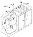
- FIG. 1is a perspective view of a grease receiving and holding system according to the present invention.
- FIG. 2is a front view of the present invention.
- FIG. 3is an enlarged view of a funnel of the present invention.
- FIG. 4is a schematic view of the present invention.
- FIGS. 1 through 4a new grease holding device embodying the principles and concepts of the present invention and generally designated by the reference numeral 10 will be described.
- the grease receiving and holding system 10generally comprises a conventional sink 12 that has a peripheral flange 14 .
- the peripheral flange 14has an opening 16 , extending therethrough.
- a housing 18is mounted below a plane of the peripheral flange of the sink 12 , such as within a cabinet holding the sink 12 .
- the housing 18has a bottom wall 20 , a top wall 22 and a peripheral wall 24 extending between and is attached to the top 22 and bottom 20 walls.
- a pipe 26has a first end 28 and a second end 30 .
- the first end 28is fluidly coupled to the housing 18 and more preferably to the top wall 22 of the housing 18 .
- the second end 30is positioned adjacent to the opening 16 .
- the pipe 26is selectively telescoping, particularly adjacent to the second end 30 .
- a funnel 32is fluidly attached to the second end 30 of the pipe 26 .
- the funnel 32has an upper edge 34 that has a diameter is substantially equal to a diameter of the opening 16 .
- a peripheral lip 36is attached to and extends around the upper edge 34 .
- the peripheral lip 36is abuttable against the flange 14 when the funnel 32 is positioned in the opening to define a stored position.
- the lip 36is selectively abuttable against or positionable above the flange 14 .
- a grip 38is attached to the peripheral lip 36 to aid a person in lifting the funnel 32 upwardly from the sink 12 to aid in its usage.
- a heating assembly 40is in communication with an interior 42 of the housing 18 for selective heating the interior 42 .
- the heating assembly 40includes at least one conventional heating conduit 44 positioned within the housing 18 .
- the heating conduit 44is ideally comprised of heating coils that are electrically insulated.
- a power supply 46electrically coupled to the heating conduit 44 .
- the power supply 46may include a conventional power cord.
- An actuator 48is electrically coupled to the power supply 46 for selectively turning the power supply 46 on or off.
- a drainpipe 50is fluidly coupled to the housing 18 .
- a valve 52is fluidly coupled to the drainpipe 50 for selectively opening or closing the drainpipe 50 .
- the drainpipe 50is positioned generally adjacent to the bottom wall 20 of the housing 18 .
- greasemay be poured down the funnel 32 and into the housing 18 . This procedure is made easier by allowing a person to pull the funnel 32 upwardly away from the sink 12 .
- the greaseis stored in the housing 18 where it may begin to solidify.
- the heating assembly 40is turned on liquefy the grease and the valve 52 is opened to pour the grease out of the housing 18 and into a container 54 .
- a removably liner 56may be provided with the container 54 so that the container 54 does not need to be cleaned after its use.
Landscapes
- Engineering & Computer Science (AREA)
- Food Science & Technology (AREA)
- Combinations Of Kitchen Furniture (AREA)
- Sink And Installation For Waste Water (AREA)
Abstract
Description
Claims (10)
Priority Applications (1)
| Application Number | Priority Date | Filing Date | Title |
|---|---|---|---|
| US11/002,915US7377210B1 (en) | 2004-12-03 | 2004-12-03 | Grease receiving and holding system |
Applications Claiming Priority (1)
| Application Number | Priority Date | Filing Date | Title |
|---|---|---|---|
| US11/002,915US7377210B1 (en) | 2004-12-03 | 2004-12-03 | Grease receiving and holding system |
Publications (1)
| Publication Number | Publication Date |
|---|---|
| US7377210B1true US7377210B1 (en) | 2008-05-27 |
Family
ID=39426770
Family Applications (1)
| Application Number | Title | Priority Date | Filing Date |
|---|---|---|---|
| US11/002,915Active - Reinstated2026-08-02US7377210B1 (en) | 2004-12-03 | 2004-12-03 | Grease receiving and holding system |
Country Status (1)
| Country | Link |
|---|---|
| US (1) | US7377210B1 (en) |
Cited By (9)
| Publication number | Priority date | Publication date | Assignee | Title |
|---|---|---|---|---|
| US8016150B1 (en)* | 2007-07-20 | 2011-09-13 | Bunch James H | Used cooking grease disposal and storage device |
| US20130032041A1 (en)* | 2011-08-02 | 2013-02-07 | Gerhard Kramer | Cooking device with fat drain |
| US20150101972A1 (en)* | 2012-01-18 | 2015-04-16 | Sal Coco | Cooking oil storage and filtration system |
| US9192265B1 (en) | 2012-10-16 | 2015-11-24 | Jeffrey A. Johnson | Grease collector receptacle and cooking utensil for use therewith |
| US20160194098A1 (en)* | 2015-01-07 | 2016-07-07 | Larry Vegh | Liquid soap filling device |
| US20170215636A1 (en)* | 2016-01-29 | 2017-08-03 | Evo, Inc. | Indoor/Outdoor Cooking System |
| US10376101B2 (en)* | 2012-01-18 | 2019-08-13 | Sal Coco | Cooking oil storage and filtration system |
| US10463197B2 (en) | 2012-01-18 | 2019-11-05 | Sal Coco | Cooking oil storage and filtration system |
| US20200122061A1 (en)* | 2018-10-23 | 2020-04-23 | Linda Lackey | Cooking oil disposal assembly |
Citations (9)
| Publication number | Priority date | Publication date | Assignee | Title |
|---|---|---|---|---|
| US2353993A (en)* | 1943-04-26 | 1944-07-18 | Cavicchioli Mario | Waste and grease trap |
| US4472277A (en) | 1982-08-11 | 1984-09-18 | Christopher Bailey | Grease trap |
| US4909137A (en) | 1988-11-28 | 1990-03-20 | Giuliano Brugnoli | Cooking grill grease catcher |
| US5086619A (en)* | 1990-06-15 | 1992-02-11 | Nicolet Instrument Corporation | Filler apparatus for providing cryogenic liquid coolant to dewars such as those used in radiation detectors |
| US5492619A (en) | 1994-04-12 | 1996-02-20 | Clearline Systems, Inc. | Automatic grease collection system |
| US5713265A (en) | 1996-06-10 | 1998-02-03 | Maytag Corporation | Grease transfer system for grill ranges |
| US5823097A (en) | 1997-06-10 | 1998-10-20 | Dirck; Ronald L. | Device for storing and transferring waste cooking oil |
| US5832810A (en) | 1997-01-10 | 1998-11-10 | Marine Kleen, Inc. | Cooking fluid container and storage system and method |
| US7137419B1 (en)* | 2005-12-28 | 2006-11-21 | Dylan Reeves | Used cooking oil processing apparatus |
- 2004
- 2004-12-03USUS11/002,915patent/US7377210B1/enactiveActive - Reinstated
Patent Citations (9)
| Publication number | Priority date | Publication date | Assignee | Title |
|---|---|---|---|---|
| US2353993A (en)* | 1943-04-26 | 1944-07-18 | Cavicchioli Mario | Waste and grease trap |
| US4472277A (en) | 1982-08-11 | 1984-09-18 | Christopher Bailey | Grease trap |
| US4909137A (en) | 1988-11-28 | 1990-03-20 | Giuliano Brugnoli | Cooking grill grease catcher |
| US5086619A (en)* | 1990-06-15 | 1992-02-11 | Nicolet Instrument Corporation | Filler apparatus for providing cryogenic liquid coolant to dewars such as those used in radiation detectors |
| US5492619A (en) | 1994-04-12 | 1996-02-20 | Clearline Systems, Inc. | Automatic grease collection system |
| US5713265A (en) | 1996-06-10 | 1998-02-03 | Maytag Corporation | Grease transfer system for grill ranges |
| US5832810A (en) | 1997-01-10 | 1998-11-10 | Marine Kleen, Inc. | Cooking fluid container and storage system and method |
| US5823097A (en) | 1997-06-10 | 1998-10-20 | Dirck; Ronald L. | Device for storing and transferring waste cooking oil |
| US7137419B1 (en)* | 2005-12-28 | 2006-11-21 | Dylan Reeves | Used cooking oil processing apparatus |
Cited By (13)
| Publication number | Priority date | Publication date | Assignee | Title |
|---|---|---|---|---|
| US8016150B1 (en)* | 2007-07-20 | 2011-09-13 | Bunch James H | Used cooking grease disposal and storage device |
| US10001283B2 (en)* | 2011-08-02 | 2018-06-19 | Rational Aktiengesellschaft | Cooking device with fat drain |
| US20130032041A1 (en)* | 2011-08-02 | 2013-02-07 | Gerhard Kramer | Cooking device with fat drain |
| US20150101972A1 (en)* | 2012-01-18 | 2015-04-16 | Sal Coco | Cooking oil storage and filtration system |
| US10463197B2 (en) | 2012-01-18 | 2019-11-05 | Sal Coco | Cooking oil storage and filtration system |
| US10376101B2 (en)* | 2012-01-18 | 2019-08-13 | Sal Coco | Cooking oil storage and filtration system |
| US9192265B1 (en) | 2012-10-16 | 2015-11-24 | Jeffrey A. Johnson | Grease collector receptacle and cooking utensil for use therewith |
| US9877616B2 (en)* | 2015-01-07 | 2018-01-30 | Larry Vegh | Liquid soap filling device |
| US20160194098A1 (en)* | 2015-01-07 | 2016-07-07 | Larry Vegh | Liquid soap filling device |
| US10327584B2 (en)* | 2016-01-29 | 2019-06-25 | Evo, Inc. | Indoor/outdoor cooking system |
| US20170215636A1 (en)* | 2016-01-29 | 2017-08-03 | Evo, Inc. | Indoor/Outdoor Cooking System |
| US20200122061A1 (en)* | 2018-10-23 | 2020-04-23 | Linda Lackey | Cooking oil disposal assembly |
| US10857489B2 (en)* | 2018-10-23 | 2020-12-08 | Linda Lackey | Cooking oil disposal assembly |
Similar Documents
| Publication | Publication Date | Title |
|---|---|---|
| US7305793B1 (en) | Lure organizing device | |
| US7377210B1 (en) | Grease receiving and holding system | |
| EP2848174B1 (en) | Vacuum cleaner with a drain system and method for the vacuum cleaner | |
| US9675013B2 (en) | Watering device intended to be fitted to a growing container, comprising an independent reservoir | |
| US7155860B1 (en) | Umbrella mountable flower pot apparatus | |
| US20150225932A1 (en) | Multi-purpose Hand Washing Station | |
| US20200017292A1 (en) | Vacuum-Integrated Trash Bin | |
| US11248385B2 (en) | Lid and strainer basket assembly and pool skimmer incorporating same | |
| CN105525659A (en) | a sink filter | |
| JP7236240B2 (en) | sink | |
| CN208189355U (en) | A kind of Oiltank structure of oil-immersed transformer | |
| US9732503B1 (en) | Clean water conservation tank for a toilet | |
| CN108755852A (en) | A kind of family kitchen sink | |
| JPH0627554Y2 (en) | Container | |
| CN104687998B (en) | Cooking apparatus | |
| JPS5841253Y2 (en) | watering box | |
| KR200386616Y1 (en) | Food trash can | |
| US8950444B2 (en) | Portable pump and container assembly | |
| JPH061474U (en) | Sink waste storage drainage device | |
| JP2559749Y2 (en) | Waste storage and drainage device for sink | |
| CN208499369U (en) | A kind of underground dustbin | |
| CN209853027U (en) | Indoor garbage can | |
| JP3035674U (en) | Hose reel with storage device | |
| JPS6022132Y2 (en) | drainage equipment | |
| KR20150123090A (en) | A Folder Type Of Portable Water Bottle |
Legal Events
| Date | Code | Title | Description |
|---|---|---|---|
| FPAY | Fee payment | Year of fee payment:4 | |
| FEPP | Fee payment procedure | Free format text:PETITION RELATED TO MAINTENANCE FEES DISMISSED (ORIGINAL EVENT CODE: PMFS); ENTITY STATUS OF PATENT OWNER: MICROENTITY | |
| FEPP | Fee payment procedure | Free format text:PETITION RELATED TO MAINTENANCE FEES FILED (ORIGINAL EVENT CODE: PMFP); ENTITY STATUS OF PATENT OWNER: MICROENTITY | |
| FEPP | Fee payment procedure | Free format text:PETITION RELATED TO MAINTENANCE FEES FILED (ORIGINAL EVENT CODE: PMFP); ENTITY STATUS OF PATENT OWNER: MICROENTITY | |
| REMI | Maintenance fee reminder mailed | ||
| LAPS | Lapse for failure to pay maintenance fees | ||
| REIN | Reinstatement after maintenance fee payment confirmed | ||
| FP | Lapsed due to failure to pay maintenance fee | Effective date:20160527 | |
| FPAY | Fee payment | Year of fee payment:8 | |
| SULP | Surcharge for late payment | ||
| FEPP | Fee payment procedure | Free format text:PETITION RELATED TO MAINTENANCE FEES DISMISSED (ORIGINAL EVENT CODE: PMFS); ENTITY STATUS OF PATENT OWNER: MICROENTITY Free format text:PETITION RELATED TO MAINTENANCE FEES GRANTED (ORIGINAL EVENT CODE: PMFG); ENTITY STATUS OF PATENT OWNER: MICROENTITY | |
| PRDP | Patent reinstated due to the acceptance of a late maintenance fee | Effective date:20170501 | |
| STCF | Information on status: patent grant | Free format text:PATENTED CASE | |
| MAFP | Maintenance fee payment | Free format text:PAYMENT OF MAINTENANCE FEE, 12TH YEAR, MICRO ENTITY (ORIGINAL EVENT CODE: M3553); ENTITY STATUS OF PATENT OWNER: MICROENTITY Year of fee payment:12 |