US7375631B2 - Enabling and disabling a wireless RFID portable transponder - Google Patents
Enabling and disabling a wireless RFID portable transponderDownload PDFInfo
- Publication number
- US7375631B2 US7375631B2US10/899,489US89948904AUS7375631B2US 7375631 B2US7375631 B2US 7375631B2US 89948904 AUS89948904 AUS 89948904AUS 7375631 B2US7375631 B2US 7375631B2
- Authority
- US
- United States
- Prior art keywords
- card
- antenna
- shielding
- transponder
- memory
- Prior art date
- Legal status (The legal status is an assumption and is not a legal conclusion. Google has not performed a legal analysis and makes no representation as to the accuracy of the status listed.)
- Expired - Lifetime, expires
Links
Images


Classifications
- H—ELECTRICITY
- H01—ELECTRIC ELEMENTS
- H01Q—ANTENNAS, i.e. RADIO AERIALS
- H01Q1/00—Details of, or arrangements associated with, antennas
- H01Q1/12—Supports; Mounting means
- H01Q1/22—Supports; Mounting means by structural association with other equipment or articles
- H01Q1/2208—Supports; Mounting means by structural association with other equipment or articles associated with components used in interrogation type services, i.e. in systems for information exchange between an interrogator/reader and a tag/transponder, e.g. in Radio Frequency Identification [RFID] systems
- H01Q1/2225—Supports; Mounting means by structural association with other equipment or articles associated with components used in interrogation type services, i.e. in systems for information exchange between an interrogator/reader and a tag/transponder, e.g. in Radio Frequency Identification [RFID] systems used in active tags, i.e. provided with its own power source or in passive tags, i.e. deriving power from RF signal
- G—PHYSICS
- G06—COMPUTING OR CALCULATING; COUNTING
- G06K—GRAPHICAL DATA READING; PRESENTATION OF DATA; RECORD CARRIERS; HANDLING RECORD CARRIERS
- G06K19/00—Record carriers for use with machines and with at least a part designed to carry digital markings
- G06K19/06—Record carriers for use with machines and with at least a part designed to carry digital markings characterised by the kind of the digital marking, e.g. shape, nature, code
- G06K19/067—Record carriers with conductive marks, printed circuits or semiconductor circuit elements, e.g. credit or identity cards also with resonating or responding marks without active components
- G06K19/07—Record carriers with conductive marks, printed circuits or semiconductor circuit elements, e.g. credit or identity cards also with resonating or responding marks without active components with integrated circuit chips
- G06K19/073—Special arrangements for circuits, e.g. for protecting identification code in memory
- G06K19/07309—Means for preventing undesired reading or writing from or onto record carriers
- G06K19/07318—Means for preventing undesired reading or writing from or onto record carriers by hindering electromagnetic reading or writing
- G06K19/07327—Passive means, e.g. Faraday cages
- H—ELECTRICITY
- H01—ELECTRIC ELEMENTS
- H01Q—ANTENNAS, i.e. RADIO AERIALS
- H01Q1/00—Details of, or arrangements associated with, antennas
- H01Q1/52—Means for reducing coupling between antennas; Means for reducing coupling between an antenna and another structure
- H01Q1/526—Electromagnetic shields
Definitions
- the present inventionis related to providing wireless portable transponders, such as cards and RFID tags, with user controlled mechanical protection from an unauthorized interrogation. More particularly, the invention provides mechanical means that permit a user to decide when transponder reception/interrogation of personal or other information is desirable.
- Portable transpondersemploy RFID, Radio Frequency Identification, as the technology used to collect highway tolls, to serve as personal identification for access control, and to provide means for electronic information interchange, such as credit, etc.
- Passive RFID tags and wireless cardscontain chips, (also known as computer chips, microchips, memory chips) which store identification and other information, such as credit card numbers, financial data, etc. Tags may be applied to items to identify the item in much the same way that bar codes are used. Information is retrieved from a tag as well as the wireless cards of the present invention by an RFID base station or reader when the tag or card is scanned with radio waves by the reader. The tags may draw their power to function from the interrogation field supplied by the base (read/write) station.
- the RFID tag or deviceincludes a circuit typically a silicon chip, although more than one chip may be used in the construction of the RFID device.
- the circuitis generally connected to an antenna.
- the RFID device or cardmay take on a variety of forms including that of a tag, a key fob, or a card.
- a batterymay also be employed to extend the range of the device. It is also possible in principle to build devices that function as tags or wireless cards using electrical circuits including only resistors, capacitors and inductors as is well known by those skilled in the art. In some cases the circuit acts as an antenna and thus a separate antenna is not used.
- non-electrical circuit memory deviceswhich are responsive to interrogation, that may be used to construct identification devices contained within cards and tags.
- Examples of such memory devicesinclude magnetic devices, or wires such as those described in U.S. Pat. No. 5,538,803, “Multibit Tag Using Barkhausen Effect,” resonant structures such as are describe in U.S. Pat. No. 5,563,583, “Multibit Magnetic Radiofrequency Tag Using Micromechanics,” and U.S. Pat. No. 5,581,257, “Radio Frequency Automatic Identification System”.
- Radio Frequency IdentificationRFID
- taggingfor supply chain tracking of goods. Demonstrations of RFID for item tagging will lead to point of sale check out and data collection.
- merchantsare issuing credit/debit cards that allow a holder to be identified upon entering a place selling merchandise or at the point of sale.
- This cardmay be in the form of a credit card that has in it an RFID chip positioned between laminates of the card as well as an antenna attached to the chip, also generally placed within the card laminates. Since the card communicates by a wireless means, it may take other physical forms.
- Speedpasssee www.speedpass.com
- Speedpassis a wireless RFID credit device that has the form of a small cylinder. It is a key fob carried on a key chain.
- American Expresshas introduced an RFID credit card, ExpessPay, which is in the form of a rectangular key fob.
- An aspect of the present inventionis to provide transponder information exchange privacy and control by mechanically activating and deactivating at least the RFID portion of the transponder, or card.
- Another aspect of the present inventionis to enable a holder of a card to protect his/her privacy by shielding, effectively deactivating, the RFID portion of the card at will, while also making it possible to reactivate the card or tag at the holder's discretion.
- activation and deactivation of the RFID portion of the transponder, tag or cardmakes it possible for the user of the tag or card to select whether or not additional information should be entered onto the card or tag from known or unknown sources.
- a further aspect of the present inventionis to provide means for activating/deactivating a tag in a manner that causes little or no disruption to the intrinsic transponder, card or tag operating system.
- a moveable piece of materialis secured to the transponder, tag, fob or card that can be manually moved or slid in positions to (1) allow the antenna of the wireless device to be exposed to or (2) protect the antenna from radiation that may be used to interrogate the card.
- the inventioncan also be implemented as a shielding method by providing a card having a circuit to be controlled, and mechanically coupling a shielding member to the card to selectively shield the circuit.
- the inventionis further implemented as a shielding method which selectively moves a shielding material mechanically coupled to a card such as to block an antenna, or other receiving device, in the card from receiving an external signal.
- FIG. 1illustrates an example of a system of the invention
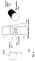
- FIG. 2shows a flow diagram illustrating a enable/disable function
- FIG. 3is an example of a wireless card, in the form of a rectangular flat card, with a slideable device deployed in a manner making it possible to disable/enable the wireless card by covering or uncovering the antenna within or on the face of the card;
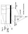
- FIG. 4shows a card containing both an antenna connected to a memory chip (not shown) and a magnetic stripe for swiping in a magnetic reader, in which the antenna can be enabled/disabled without affecting the magnetic stripe;
- FIG. 5shows a wireless “card” in the shape of a cylinder in which the antenna of FIGS. 3 and 4 is replaced by a magnetic pickup coil which can be enabled/disabled;
- FIG. 6shows a wireless card with an attached shield on a hinge
- FIG. 7shows a wireless card with an attached shield on a hinge such that the plane of the shield rotates in the plane of the card
- FIG. 8shows a card with a shield attached by means of a flexible member.
- the present inventionprovides methods, systems and apparatus to protect wireless transponders, such as cards, fobs or RFID tags that may be carried on a person, from an unauthorized interrogation.
- wireless transponderssuch as cards, fobs or RFID tags that may be carried on a person
- Such cards or tagshave means for receiving and storing electronic information, commonly in binary form using memories and/or electronic circuits, typically, but not exclusively such as chips containing ‘bits’ to store the information.
- the inventionis designed to provide privacy of this type of electronic information and yet permit the information to be queried at the users discretion. At the same time the cards and tags can be protected from receiving unauthorized or unwanted information.
- the inventionprovides means that permit a user, generally the owner, to decide when reception/interrogation of this personal information is desirable by simple mechanical means.
- advantageous means for activating/deactivating a tagis one that causes little or no disruption to the intrinsic card or tag operating system. Rather, to obtain the objective of enabling/disabling the card or tag at the card owner's choice, we impose a moveable piece of material, otherwise secured to the card that can be manually moved or slid in positions to (1) allow the antenna of the wireless device to be exposed to or (2) protect the antenna from radiation that may be used to interrogate the card.
- This shielding devicecan for example block (or cover) the card antenna preventing it from receiving an interrogation signal. The shield may be deployed, for example, when the RFID card is not in use to prevent the unauthorized detection or reading of the RFID device.
- the owner of the cardmay want to be recognized when entering an establishment in which case the slideable shielding device is positioned so as to uncover the antenna to allow the antenna to function normally.
- the term cardincludes any type of portable transponder.
- the wireless portable transpondera card and/or tag, may have a dual purpose, that is it may act as a magnetic swipe card while also having the RFID identification.
- FIG. 1illustrates a system of the invention 100 .
- a person or cardholder 110carries at least one wireless card or identification card 120 .
- the cardbeing interrogated by an RFID reader, the reading transmitted to a computing network.
- the cardmay be read through the use of an electromagnetic, EM, signal 160 that provides means for communication between the card 120 and a reader 150 .
- Information received by the reader 150may be transferred to a computing system 170 where it is processed and stored in a database.
- the system 170may in turn be connected to a network 180 which makes possible the exchange of information with other computing systems.
- the card 120is constructed with a built in deployable or slideable shield to screen magnetic or electric components or both of EM waves.
- the novel feature of the present inventionis the deployable or slideable shield, described in detail in FIGS. 3 , 4 , 5 , 6 , 7 , and 8 , which can be used to prevent the antenna or the pickup coil from being exposed to a field for the purpose of interrogation of the card or placing additional information on the card.
- Mu metalis the generic name for materials that have a very high magnetic permeability.
- mu metal and Metglas Rare alloy compositions which are basically permalloy or nickel-iron with varying amounts of cobalt, boron and other trace materials. In addition, these materials are designed to have exceedingly high permeabilities, on the order of 10 thousand to 1 million. Therefore, a circuit surrounded by such material can readily be protected from magnetic radiation depending on the thickness of the alloy, the alloy's coercive force, i.e.
- ⁇represents the depth, skin depth, within the shield at which the incident field has fallen to 37 percent of its incident value.
- This thicknesswill also be effective at all of the higher frequencies, 434 MHz and above, where electric field coupling is generally used.
- a copper thickness0.02 to 0.05 cm, at least an order of magnitude more than is needed, to attenuate any interrogation signal at 14.56 MHz and above.
- RFID cardsthat use magnetic coupling operate at frequencies of about 100 kHz to 14.5 MHz.
- mu metal or a Metglaswith relatively high coercive force (greater than 10 Oersteds).
- a mu metal thickness of about 10 ⁇ 3 cm or greaterwould work as a shield for any frequency at or above 100 kHz.
- FIG. 2shows a flow diagram 200 illustrating the enable/disable function.
- the shieldingIn the normal state of use for a card, the shielding is in a deployed position 205 to protect the privacy of the user. If the shielding is desired 210 , no more is done. If the shielding is not desired 210 , e.g. the user wishes that the card may be read, the shielding is withdrawn 215 and the card may be used. After the card is used, the shielding may be deployed again 220 to shield the card. In general, friction between the slideable element and the card holds the element in place.
- FIG. 3is an example of a card with the slideable device deployed in a manner making it possible to disable/enable the wireless card by covering or uncovering the antenna within or on the face of the card.
- the card 300is disabled by shielding the antenna 301 that is embedded (or may be on the surface of) in the card from receiving electromagnetic waves.
- the cardcontains a slideable, thin metallic section 302 that may be deployed or withdrawn.
- the metallic sectionmay consist of a material that has a high magnetic permeability or a high electrical conductivity or both. Most high-permeability magnetic materials will also have sufficient electrical conductivity to shield both the magnetic and electric components of electromagnetic waves. Examples of such materials include mu metal and Alloy-42, a nickel-iron alloy (permalloy).
- Low frequency, LF, and high frequency (low MHz range), HF, RFID devicesare generally read by means of magnetic coupling, while ultrahigh frequency, UHF, and microwave RFID tags are read by means of electric field coupling. Copper or aluminum may be used to shield UHF and microwave RFID devices.
- the slideable memberis slid over the section containing the antenna thereby making the antenna unable to receive an RF signal. This prevents identification.
- the slideable mechanismmay be attached by small indentations in the card acting as rails 305 .
- Slider stops 306may be built into the card to keep the sliding shield on the card or moving more than necessary. Additionally, slider position markings 304 may be placed on the card to aid in the deployment of the shield.
- FIG. 4shows a card 400 containing both an antenna 401 connected to a chip (not shown) and a magnetic stripe 403 for swiping in a reader.
- the antennacan be enabled/disabled without affecting the magnetic stripe. Since the card is also used as a conventional credit card with a magnetic stripe on one side, the magnetic shielding material 405 envelopes the portion of the card that contains the antenna. The slidable portion is positioned and retained on the card by the use of a through slot 402 as shown in the figure.
- FIG. 5shows a wireless “card” in the shape of a cylinder where the antenna of FIGS. 3 and 4 is replaced by a magnetic pickup coil 501 which can be enabled/disabled.
- retractable shieldingto deactivate RFID devices of cards shaped other than the standard credit card shape.
- Cylindrical RFID cards or tagssuch as tag 500
- a deployable cylindrical shield 502also constructed of the appropriate material described above.
- the tag with shield in placeis shown in perspective view 503 . When the shield is moved to one end of the tag to uncover the antenna, the tag functions normally. Stops, not shown, may be used to keep the sliding portion integral with the cylindrical tag.
- other mechanical constructsmay be used to join movable or deployable shields to wireless cards. These may include hinges, rotating assemblies, or envelopes attached by means of flexible members.
- FIG. 6shows a card 610 with an attached shield 620 on a hinge 630 .
- the card 610is attached to the shield 620 by means of the hinge 630 .
- the shieldmay be rotated 640 on the hinge in a direction out of the plane of the card to either cover or uncover the card.
- a second rotatable shield(not shown), similar to shield 620 , would be placed on the hinge so as to be able to cover the opposite side of the card.
- FIG. 7shows a card 710 with an attached shield 720 on a hinge such that the plane of the shield rotates in the plane of the card 740 .
- the card 710is attached to the shield 720 by means of the hinge 730 .
- the shieldmay be rotated 740 in the plane of the card to either cover or uncover the card.
- a second shield on the opposite side of the cardmay be used to completely shield the card.
- FIG. 8shows a card with a shield 820 attached by means of a flexible member 830 .
- the card 810may be placed 840 within the shield 820 to shield the card.
- the flexible member 830may be a string, a chain, or a wire.
- the present inventionincludes a card, fob or tag comprising a memory, or an electrical circuit, embedded within the card in combination (usually though not always) with an antenna embedded within the card, the antenna electrically connected to the circuit.
- the card or tagalso has a deployable member mechanically coupled to the card, with the deployable member having electromagnetic shielding capability. The member can be selectively placed to control reception of the antenna of a signal for the electrical circuit.
- the shielding method or controlincludes the shielding member having at least one position to completely shield the antenna (or in some cases a circuit not requiring an antenna) from the signal; the antenna is on an exterior surface of the card or laminated within the card; a chip is mounted on an exterior surface or within the lamination of the card; control of the deployable member includes mechanical movement so as to cover and uncover the antenna; the deployable member includes a shielding material taken from a group of shielding materials such as magnetic, electrical materials; and/or the mechanical movement of the deployable member can be such that the member is held by way of a slot in the card.
- magnétique materialsare mu metal, Metglas Reg. and any combination of these.
- mu metalbe at least 0.001 centimeters thick.
- the thickness of the deployable memberis such that the skin depth is less than the thickness of the deployable shielding member.
- Shielding capabilityincludes selecting materials having at least one of high magnetic permeability and high electrical conductivity.
- the signal for which shielding is selectively soughtincludes an interrogation signal of the interrogation circuit or a signal that can impart information on the electrical circuit such as a chip or microchip.
- the deployable shieldis coupled in a slideably or otherwise mechanically adjustable manner.
- the deployable membermay include an insulating material (wood, plastic or the like, for example several 10's of mils in thickness).
- This insulating deployable memberhas on its entire inner or outer surface area a thin deposition of a metallic layer (in the range of 1–5000 Angstroms that completely encompasses the inner or outer surface area of the deployable member. This thin metallic layer acts to shield the tag from the aforementioned high frequencies.
- the inventioncan also be implemented as a shielding method by providing a card having a memory or circuit to be controlled, and mechanically coupling a shielding member to the card to selectively shield the circuit.
- the inventionis further implemented as a shielding method comprising by selectively moving a shielding material mechanically coupled to the card such as to block an antenna in the card from receiving an external signal.
- the inventioncan also be implemented as means for selectively moving a shielding material mechanically coupled to said card such as to block an antenna within a lamination of a card or on the surface of a card from receiving an external signal.
- the inventionmay also be implemented to shield non-electrical circuit memory devices.
- the inventioncan also be implemented as a portable transponder having a memory or circuit.
- the transpondercomprising: a non-electrical circuit memory device, a deployable member mechanically coupled to the transponder, the member having electromagnetic shielding capability to shield the circuit from a signal intended for the circuit, and the member being selectively placed as to enable a user to control reception by the circuit of a signal intended for said electrical circuit.
- the memory deviceis generally but not always embedded in the transponder.
- the memoryis a memory selected from a group of memories including: an electrical circuit and antenna, said antenna electrically coupled to said circuit; magnetic device; resonant structure; micromechanical device; non-electrical circuit memory device; and any combination of these circuits.
- the transponderis one of the following: a credit card, a debit card, a fob, a transaction card, and a swipeable card.
- the transponderis typically carried by a person in order for a transaction to be performed.
- the transactionincludes any giving and/or taking information to/from the card.
Landscapes
- Engineering & Computer Science (AREA)
- Physics & Mathematics (AREA)
- Electromagnetism (AREA)
- Computer Hardware Design (AREA)
- Power Engineering (AREA)
- Computer Security & Cryptography (AREA)
- General Engineering & Computer Science (AREA)
- Microelectronics & Electronic Packaging (AREA)
- General Physics & Mathematics (AREA)
- Theoretical Computer Science (AREA)
- Credit Cards Or The Like (AREA)
Abstract
Description
δ=[2/(ωσμ)]0.5 (1)
where ω, σ, μ are respectively, the angular frequency of the incident wave, electrical conductivity, and permeability of the shielding material. δ represents the depth, skin depth, within the shield at which the incident field has fallen to 37 percent of its incident value. Thus, for a depth equal to three skin depths into a shielding material, the incident field is reduced by 95 percent leaving 5 percent of the original field.
Claims (22)
Priority Applications (1)
| Application Number | Priority Date | Filing Date | Title |
|---|---|---|---|
| US10/899,489US7375631B2 (en) | 2004-07-26 | 2004-07-26 | Enabling and disabling a wireless RFID portable transponder |
Applications Claiming Priority (1)
| Application Number | Priority Date | Filing Date | Title |
|---|---|---|---|
| US10/899,489US7375631B2 (en) | 2004-07-26 | 2004-07-26 | Enabling and disabling a wireless RFID portable transponder |
Publications (2)
| Publication Number | Publication Date |
|---|---|
| US20060017570A1 US20060017570A1 (en) | 2006-01-26 |
| US7375631B2true US7375631B2 (en) | 2008-05-20 |
Family
ID=35656543
Family Applications (1)
| Application Number | Title | Priority Date | Filing Date |
|---|---|---|---|
| US10/899,489Expired - LifetimeUS7375631B2 (en) | 2004-07-26 | 2004-07-26 | Enabling and disabling a wireless RFID portable transponder |
Country Status (1)
| Country | Link |
|---|---|
| US (1) | US7375631B2 (en) |
Cited By (60)
| Publication number | Priority date | Publication date | Assignee | Title |
|---|---|---|---|---|
| US20070034518A1 (en)* | 2005-08-15 | 2007-02-15 | Virgin Islands Microsystems, Inc. | Method of patterning ultra-small structures |
| US20070152176A1 (en)* | 2006-01-05 | 2007-07-05 | Virgin Islands Microsystems, Inc. | Selectable frequency light emitter |
| US20070152781A1 (en)* | 2006-01-05 | 2007-07-05 | Virgin Islands Microsystems, Inc. | Switching micro-resonant structures by modulating a beam of charged particles |
| US20070253535A1 (en)* | 2006-04-26 | 2007-11-01 | Virgin Islands Microsystems, Inc. | Source of x-rays |
| US20070252089A1 (en)* | 2006-04-26 | 2007-11-01 | Virgin Islands Microsystems, Inc. | Charged particle acceleration apparatus and method |
| US20070257620A1 (en)* | 2006-05-05 | 2007-11-08 | Virgin Islands Microsystems, Inc. | Coupled nano-resonating energy emitting structures |
| US20070258690A1 (en)* | 2006-05-05 | 2007-11-08 | Virgin Islands Microsystems, Inc. | Integration of electromagnetic detector on integrated chip |
| US20070258675A1 (en)* | 2006-05-05 | 2007-11-08 | Virgin Islands Microsystems, Inc. | Multiplexed optical communication between chips on a multi-chip module |
| US20070257738A1 (en)* | 2006-05-05 | 2007-11-08 | Virgin Islands Microsystems, Inc. | Top metal layer shield for ultra-small resonant structures |
| US20080073590A1 (en)* | 2006-09-22 | 2008-03-27 | Virgin Islands Microsystems, Inc. | Free electron oscillator |
| US20080094224A1 (en)* | 2006-10-23 | 2008-04-24 | Cascade Engineering, Inc. | Rfid-enabled waste/recycling cart |
| US20080284606A1 (en)* | 2007-05-14 | 2008-11-20 | Nec (China) Co., Ltd. | Radio frequency identification tag apparatus |
| US20090002167A1 (en)* | 2007-06-29 | 2009-01-01 | Oberthur Card Systems Sa | Dual communication fob assembly comprising an insert within a base |
| WO2007130087A3 (en)* | 2006-05-05 | 2009-05-14 | Virgin Islands Microsystems | Shielding of integrated circuit package with high-permeability magnetic material |
| US20090159670A1 (en)* | 2007-12-24 | 2009-06-25 | Dynamics Inc. | Cards and devices with multifunction magnetic emulators and methods for using the same |
| US7557647B2 (en) | 2006-05-05 | 2009-07-07 | Virgin Islands Microsystems, Inc. | Heterodyne receiver using resonant structures |
| US7557365B2 (en) | 2005-09-30 | 2009-07-07 | Virgin Islands Microsystems, Inc. | Structures and methods for coupling energy from an electromagnetic wave |
| US7558490B2 (en) | 2006-04-10 | 2009-07-07 | Virgin Islands Microsystems, Inc. | Resonant detector for optical signals |
| US7569836B2 (en) | 2006-05-05 | 2009-08-04 | Virgin Islands Microsystems, Inc. | Transmission of data between microchips using a particle beam |
| US7573045B2 (en) | 2006-05-15 | 2009-08-11 | Virgin Islands Microsystems, Inc. | Plasmon wave propagation devices and methods |
| US7579609B2 (en) | 2005-12-14 | 2009-08-25 | Virgin Islands Microsystems, Inc. | Coupling light of light emitting resonator to waveguide |
| US7579954B1 (en)* | 2007-01-19 | 2009-08-25 | Burkley Robert W | System and method of shielding objects utilizing RFID technology |
| US7583370B2 (en) | 2006-05-05 | 2009-09-01 | Virgin Islands Microsystems, Inc. | Resonant structures and methods for encoding signals into surface plasmons |
| US7586097B2 (en) | 2006-01-05 | 2009-09-08 | Virgin Islands Microsystems, Inc. | Switching micro-resonant structures using at least one director |
| US7586167B2 (en) | 2006-05-05 | 2009-09-08 | Virgin Islands Microsystems, Inc. | Detecting plasmons using a metallurgical junction |
| US7605835B2 (en) | 2006-02-28 | 2009-10-20 | Virgin Islands Microsystems, Inc. | Electro-photographic devices incorporating ultra-small resonant structures |
| US7626179B2 (en) | 2005-09-30 | 2009-12-01 | Virgin Island Microsystems, Inc. | Electron beam induced resonance |
| US7646991B2 (en) | 2006-04-26 | 2010-01-12 | Virgin Island Microsystems, Inc. | Selectable frequency EMR emitter |
| US7655934B2 (en) | 2006-06-28 | 2010-02-02 | Virgin Island Microsystems, Inc. | Data on light bulb |
| US7656094B2 (en) | 2006-05-05 | 2010-02-02 | Virgin Islands Microsystems, Inc. | Electron accelerator for ultra-small resonant structures |
| US7659513B2 (en) | 2006-12-20 | 2010-02-09 | Virgin Islands Microsystems, Inc. | Low terahertz source and detector |
| US7679067B2 (en) | 2006-05-26 | 2010-03-16 | Virgin Island Microsystems, Inc. | Receiver array using shared electron beam |
| US7688274B2 (en) | 2006-02-28 | 2010-03-30 | Virgin Islands Microsystems, Inc. | Integrated filter in antenna-based detector |
| US20100102131A1 (en)* | 2008-10-28 | 2010-04-29 | First Data Corporation | Systems and Methods for Disabling a Contactless Transaction Device |
| US7710040B2 (en) | 2006-05-05 | 2010-05-04 | Virgin Islands Microsystems, Inc. | Single layer construction for ultra small devices |
| US7718977B2 (en) | 2006-05-05 | 2010-05-18 | Virgin Island Microsystems, Inc. | Stray charged particle removal device |
| US7732786B2 (en) | 2006-05-05 | 2010-06-08 | Virgin Islands Microsystems, Inc. | Coupling energy in a plasmon wave to an electron beam |
| US7741934B2 (en) | 2006-05-05 | 2010-06-22 | Virgin Islands Microsystems, Inc. | Coupling a signal through a window |
| US7746532B2 (en) | 2006-05-05 | 2010-06-29 | Virgin Island Microsystems, Inc. | Electro-optical switching system and method |
| US7791291B2 (en) | 2005-09-30 | 2010-09-07 | Virgin Islands Microsystems, Inc. | Diamond field emission tip and a method of formation |
| US7791053B2 (en) | 2007-10-10 | 2010-09-07 | Virgin Islands Microsystems, Inc. | Depressed anode with plasmon-enabled devices such as ultra-small resonant structures |
| US20100252514A1 (en)* | 2009-04-03 | 2010-10-07 | Min-Ju Chung | Foldable baseball equipment rack |
| US20100263179A1 (en)* | 2006-05-08 | 2010-10-21 | Charles Donald Boldin | LINING FOR BLOCKING WI-FI, ULTRA-SOUND, LASER, VHF, UHF, BLUE TOOTH, AND RFlD TAG SIGNAL |
| US7876793B2 (en) | 2006-04-26 | 2011-01-25 | Virgin Islands Microsystems, Inc. | Micro free electron laser (FEL) |
| US7986113B2 (en) | 2006-05-05 | 2011-07-26 | Virgin Islands Microsystems, Inc. | Selectable frequency light emitter |
| US7990336B2 (en) | 2007-06-19 | 2011-08-02 | Virgin Islands Microsystems, Inc. | Microwave coupled excitation of solid state resonant arrays |
| US20110310542A1 (en)* | 2010-06-21 | 2011-12-22 | Rick Welch | Vehicle mounted directionally focused tolling device enclosure |
| US8188431B2 (en) | 2006-05-05 | 2012-05-29 | Jonathan Gorrell | Integration of vacuum microelectronic device with integrated circuit |
| US8485446B1 (en)* | 2011-03-28 | 2013-07-16 | Dynamics Inc. | Shielded magnetic stripe for magnetic cards and devices |
| US8988896B2 (en)* | 2011-12-01 | 2015-03-24 | Endress + Hauser Conducta Gesellschaft für Mess- und Regeltechnik mbH + Co. KG | Field device for automation technology |
| US20170091494A1 (en)* | 2015-09-24 | 2017-03-30 | Advanced Digital Broadcast S.A. | System and method for selective access to rfid functionality |
| US10192159B1 (en)* | 2018-08-10 | 2019-01-29 | Capital One Services, Llc | Contactless card with transmission blocking element |
| US10650199B2 (en) | 2005-02-07 | 2020-05-12 | Steven Michael Colby | Passport including metallic fibers |
| US10956689B2 (en) | 2005-02-07 | 2021-03-23 | Mynette Technologies, Inc. | Passport including RFID shielding |
| US11144900B2 (en)* | 2014-09-17 | 2021-10-12 | Dashpass Inc. | Enabling card and method and system using the enabling card in a POS |
| US11170185B2 (en) | 2005-02-07 | 2021-11-09 | Steven Michael Colby | State dependent passport reading |
| US11270182B2 (en) | 2005-02-07 | 2022-03-08 | Mynette Technologies, Inc. | RFID financial device including mechanical switch |
| US11295095B2 (en) | 2005-02-07 | 2022-04-05 | Mynette Technologies, Inc. | Secure reading of passport RFID tags |
| US11347949B2 (en) | 2005-05-06 | 2022-05-31 | Mynette Technologies, Inc. | Cellular device including inductive antenna |
| US20220345562A1 (en)* | 2021-04-27 | 2022-10-27 | Osom Products, Inc. | Handheld device case with activatable shield to block wireless signals |
Families Citing this family (30)
| Publication number | Priority date | Publication date | Assignee | Title |
|---|---|---|---|---|
| ATE530998T1 (en)* | 2003-07-07 | 2011-11-15 | Avery Dennison Corp | RFID DEVICE WITH CHANGEABLE CHARACTERISTICS |
| GB2419781A (en)* | 2004-10-29 | 2006-05-03 | Hewlett Packard Development Co | Packaging of a transponder device |
| WO2006107778A2 (en)* | 2005-04-01 | 2006-10-12 | Mastercard International Incorporated | System and method for protection against skimming of information from contactless cards |
| US7479882B2 (en)* | 2005-04-14 | 2009-01-20 | Flexilis, Inc. | RFID security system and methods |
| US7482925B2 (en)* | 2005-06-24 | 2009-01-27 | Visa U.S.A. | Apparatus and method to electromagnetically shield portable consumer devices |
| US7327261B2 (en)* | 2005-07-27 | 2008-02-05 | Zih Corp. | Visual identification tag deactivation |
| US8159349B2 (en)* | 2005-08-19 | 2012-04-17 | Adasa Inc. | Secure modular applicators to commission wireless sensors |
| US8917159B2 (en)* | 2005-08-19 | 2014-12-23 | CLARKE William McALLISTER | Fully secure item-level tagging |
| JP2007087032A (en)* | 2005-09-21 | 2007-04-05 | Toshiba Tec Corp | Wireless tag reader |
| IL174671A0 (en)* | 2006-03-30 | 2006-08-20 | Ely Levine | A system and case for tracking articles |
| WO2007149101A1 (en)* | 2006-06-23 | 2007-12-27 | Mastercard International Incorporated | System and method for protection against skimming of information from contactless cards |
| US7635089B2 (en)* | 2006-07-03 | 2009-12-22 | Identity Stronghold, Llc | Device for shielding reading of a contactless smartcard |
| US20090045960A1 (en)* | 2007-03-29 | 2009-02-19 | Von Gutfeld Robert J | System And Method For Protecting RFID Cards From Unauthorized Interrogation |
| US7950585B2 (en)* | 2007-04-27 | 2011-05-31 | First Data Corporation | Protected contactless card |
| US7817045B2 (en) | 2007-05-30 | 2010-10-19 | Onderko John C | Handling system for exception RFID labels |
| US8604995B2 (en)* | 2007-06-11 | 2013-12-10 | Visa U.S.A. Inc. | Shielding of portable consumer device |
| US8038068B2 (en) | 2007-11-28 | 2011-10-18 | Visa U.S.A. Inc. | Multifunction removable cover for portable payment device |
| GB0805780D0 (en)* | 2008-03-31 | 2008-04-30 | Royal Bank Of Scotland Plc The | Processor card arrangement |
| US8416079B2 (en)* | 2009-06-02 | 2013-04-09 | 3M Innovative Properties Company | Switching radio frequency identification (RFID) tags |
| FR2953619B1 (en) | 2009-12-03 | 2012-08-03 | Uint | ACTIVATION AND INDICATION OF RF FIELD ON A DEVICE COMPRISING A CHIP. |
| US8833664B2 (en)* | 2009-12-18 | 2014-09-16 | Yu Yung Choi | Enhanced performance and security RFID device |
| US8760291B1 (en) | 2011-05-17 | 2014-06-24 | Kevin W. Mullins | Notification apparatus, system, and method |
| US9183482B2 (en)* | 2012-01-13 | 2015-11-10 | Sharp Laboratories Of America, Inc. | Method and system for determining an association of a set of radio-frequency identification tags |
| US8948694B2 (en) | 2012-12-04 | 2015-02-03 | Blackberry Limited | Antenna shield for proximity-based communication devices |
| EP2741247B1 (en)* | 2012-12-04 | 2017-02-15 | BlackBerry Limited | Antenna shield for proximity-based communication devices |
| CN204130679U (en)* | 2013-09-27 | 2015-01-28 | 中兴通讯股份有限公司 | Antenna assembly and terminal |
| US10878686B1 (en)* | 2018-03-26 | 2020-12-29 | Badge Messenger Inc. | Badge holder with one touch communication |
| US11003979B1 (en)* | 2019-10-18 | 2021-05-11 | Capital One Service, LLC | Multi-faced payment card with partitioned dual smart chips and antennae |
| US11208839B2 (en)* | 2020-03-03 | 2021-12-28 | Gmi Holdings, Inc. | Space venting upward acting door system and method |
| US11412825B2 (en) | 2020-11-04 | 2022-08-16 | Identity Stronghold, Llc | Shielding card holder system |
Citations (13)
| Publication number | Priority date | Publication date | Assignee | Title |
|---|---|---|---|---|
| US4728938A (en) | 1986-01-10 | 1988-03-01 | Checkpoint Systems, Inc. | Security tag deactivation system |
| US4835524A (en) | 1987-12-17 | 1989-05-30 | Checkpoint System, Inc. | Deactivatable security tag |
| US5538803A (en) | 1994-11-23 | 1996-07-23 | International Business Machines Corporation | Multibit tag using Barkhausen effect |
| US5563583A (en) | 1994-11-23 | 1996-10-08 | International Business Machines Corporation | Multibit magnetic radio frequency tag using micromechanics |
| US5581257A (en) | 1991-09-24 | 1996-12-03 | Gordian Holding Corporation | Radio frequency automatic identification system |
| US6025780A (en) | 1997-07-25 | 2000-02-15 | Checkpoint Systems, Inc. | RFID tags which are virtually activated and/or deactivated and apparatus and methods of using same in an electronic security system |
| US6121544A (en)* | 1998-01-15 | 2000-09-19 | Petsinger; Julie Ann | Electromagnetic shield to prevent surreptitious access to contactless smartcards |
| US6181248B1 (en) | 1995-11-29 | 2001-01-30 | N.V. Nederlandsche Apparatenfabriek Nedap | Deactivatable article security label with data carrier function |
| US6317028B1 (en) | 1998-07-24 | 2001-11-13 | Electronic Security And Identification Llc | Electronic identification, control, and security system and method for consumer electronics and the like |
| US20020175873A1 (en)* | 2000-07-18 | 2002-11-28 | King Patrick F. | Grounded antenna for a wireless communication device and method |
| US20050179552A1 (en)* | 2002-09-30 | 2005-08-18 | The Furukawa Electric Co., Ltd. | RFID tag and its manufacturing method |
| US6970070B2 (en)* | 2003-05-08 | 2005-11-29 | Rsa Security Inc. | Method and apparatus for selective blocking of radio frequency identification devices |
| US20060017571A1 (en)* | 2004-05-14 | 2006-01-26 | Wavezero, Inc. | Radiofrequency antennae and identification tags and methods of manufacturing radiofrequency antennae and radiofrequency identification tags |
- 2004
- 2004-07-26USUS10/899,489patent/US7375631B2/ennot_activeExpired - Lifetime
Patent Citations (14)
| Publication number | Priority date | Publication date | Assignee | Title |
|---|---|---|---|---|
| US4728938A (en) | 1986-01-10 | 1988-03-01 | Checkpoint Systems, Inc. | Security tag deactivation system |
| US4835524A (en) | 1987-12-17 | 1989-05-30 | Checkpoint System, Inc. | Deactivatable security tag |
| US5581257A (en) | 1991-09-24 | 1996-12-03 | Gordian Holding Corporation | Radio frequency automatic identification system |
| US5538803A (en) | 1994-11-23 | 1996-07-23 | International Business Machines Corporation | Multibit tag using Barkhausen effect |
| US5563583A (en) | 1994-11-23 | 1996-10-08 | International Business Machines Corporation | Multibit magnetic radio frequency tag using micromechanics |
| US6181248B1 (en) | 1995-11-29 | 2001-01-30 | N.V. Nederlandsche Apparatenfabriek Nedap | Deactivatable article security label with data carrier function |
| EP1010152A1 (en) | 1997-07-25 | 2000-06-21 | Checkpoint Systems, Inc. | Electrically, physically or virtually reactivating rfid tags |
| US6025780A (en) | 1997-07-25 | 2000-02-15 | Checkpoint Systems, Inc. | RFID tags which are virtually activated and/or deactivated and apparatus and methods of using same in an electronic security system |
| US6121544A (en)* | 1998-01-15 | 2000-09-19 | Petsinger; Julie Ann | Electromagnetic shield to prevent surreptitious access to contactless smartcards |
| US6317028B1 (en) | 1998-07-24 | 2001-11-13 | Electronic Security And Identification Llc | Electronic identification, control, and security system and method for consumer electronics and the like |
| US20020175873A1 (en)* | 2000-07-18 | 2002-11-28 | King Patrick F. | Grounded antenna for a wireless communication device and method |
| US20050179552A1 (en)* | 2002-09-30 | 2005-08-18 | The Furukawa Electric Co., Ltd. | RFID tag and its manufacturing method |
| US6970070B2 (en)* | 2003-05-08 | 2005-11-29 | Rsa Security Inc. | Method and apparatus for selective blocking of radio frequency identification devices |
| US20060017571A1 (en)* | 2004-05-14 | 2006-01-26 | Wavezero, Inc. | Radiofrequency antennae and identification tags and methods of manufacturing radiofrequency antennae and radiofrequency identification tags |
Non-Patent Citations (17)
| Title |
|---|
| "Active Breakthrough Performance through RFID Radio Frequency Identification Technology," Internet URL: http://www.rfida.com/rfidtech.htm. |
| "ELocity Inc., Friday's Stock Focus Alerts You on RFID Technology," Florida, Apr. 16, 2004, Internet URL: boston.com. |
| "EnXnet's Emerging Technology Solves Privacy Concerns," Oklahoma, Apr. 15, 2004, Internet URL: boston.com. |
| "EnXnet's RFID Deactivation Device Vital Role in the Consumer Marketplace," Oklahoma, Apr. 20, 2004, Internet URL: boston.com. |
| "NCR Prototype Kiosk Kills RFID Tags," RFID Journal, Internet URL: http://www.rfidjournal.com/article/articleprint/585/-1/1/. |
| "Overcoming the Consumer Privacy Concerns of Product Tracking Through RFID Tags," SANS Institute 2004, Steve Hankel, GIAC Security Essentials Certification (GSEC). |
| "RFID Backlash Prompts 'Kill' Feature," by Junko Yoshida, Apr. 28, 2003, Internet URL: http://www.eetimes.com/article/showArticle.jhtml?articleid=12803964. |
| "STMicroelectronics Launches UHF RFID Chip Fully Supporting EPCglobal Class 1 Specification," Internet URL: http://www.st.com/stonline/press/news/year2004/p1462m.htm. |
| American Expess Expands Availability of New "Contactless" Payment Product Designed To Make Everyday Purchases Quick And Easy, pp. 1-3, http:/home3.americanexpress.com/corp/latestnews/expresspay.asp (as of Jul. 20, 2004). |
| ExxonMobil, 1 page-http:/www.exxonmobil.com/Siteflow/Brands/SF<SUB>-</SUB>BR<SUB>-</SUB>Speedpass.asp (as of Jul. 20, 2004). |
| E-ZPass Plus, 2 pages-http://www.panynj.gov/ezpass.html. |
| Imperial Oil, 1 page-http:/www.speedpass.ca/Cabada-English/Products/Speedpass/PS<SUB>-</SUB>S<SUB>-</SUB>SpeedpassHomePage (as of Jul. 20, 2004). |
| International Application No. WO 02/084584 published on Oct. 24, 2002. |
| Juels, A. et al. "The Blocker Tag: Selective Blocking of RFID Tags for Consumer Privacy.". |
| Magnetic Field Shielding, pp. 1-7-http:/www.lessmf.com/mag-shld.html (as of Jul. 20, 2004). |
| U.S. Appl. No. 2002/0117543 published on Aug. 29, 2002. |
| U.S. Appl. No. 2002/0149468. |
Cited By (96)
| Publication number | Priority date | Publication date | Assignee | Title |
|---|---|---|---|---|
| US7758739B2 (en) | 2004-08-13 | 2010-07-20 | Virgin Islands Microsystems, Inc. | Methods of producing structures for electron beam induced resonance using plating and/or etching |
| US11295095B2 (en) | 2005-02-07 | 2022-04-05 | Mynette Technologies, Inc. | Secure reading of passport RFID tags |
| US10650199B2 (en) | 2005-02-07 | 2020-05-12 | Steven Michael Colby | Passport including metallic fibers |
| US10956689B2 (en) | 2005-02-07 | 2021-03-23 | Mynette Technologies, Inc. | Passport including RFID shielding |
| US11170185B2 (en) | 2005-02-07 | 2021-11-09 | Steven Michael Colby | State dependent passport reading |
| US11270182B2 (en) | 2005-02-07 | 2022-03-08 | Mynette Technologies, Inc. | RFID financial device including mechanical switch |
| US11687741B1 (en) | 2005-05-06 | 2023-06-27 | Steven Michael Colby | Methods of using a cellular telephone |
| US11599734B2 (en) | 2005-05-06 | 2023-03-07 | Mynette Technologies, Inc. | Methods of inductive communication in a cellular telephone |
| US11347949B2 (en) | 2005-05-06 | 2022-05-31 | Mynette Technologies, Inc. | Cellular device including inductive antenna |
| US11989612B1 (en) | 2005-05-06 | 2024-05-21 | Mynette Technologies, Inc. | Cellular telephone including biometric sensor |
| US12039396B2 (en) | 2005-05-06 | 2024-07-16 | Steven Michael Colby | Cellular telephone including biometric control of transactions |
| US20070034518A1 (en)* | 2005-08-15 | 2007-02-15 | Virgin Islands Microsystems, Inc. | Method of patterning ultra-small structures |
| US7557365B2 (en) | 2005-09-30 | 2009-07-07 | Virgin Islands Microsystems, Inc. | Structures and methods for coupling energy from an electromagnetic wave |
| US7626179B2 (en) | 2005-09-30 | 2009-12-01 | Virgin Island Microsystems, Inc. | Electron beam induced resonance |
| US7714513B2 (en) | 2005-09-30 | 2010-05-11 | Virgin Islands Microsystems, Inc. | Electron beam induced resonance |
| US7791291B2 (en) | 2005-09-30 | 2010-09-07 | Virgin Islands Microsystems, Inc. | Diamond field emission tip and a method of formation |
| US7791290B2 (en) | 2005-09-30 | 2010-09-07 | Virgin Islands Microsystems, Inc. | Ultra-small resonating charged particle beam modulator |
| US7579609B2 (en) | 2005-12-14 | 2009-08-25 | Virgin Islands Microsystems, Inc. | Coupling light of light emitting resonator to waveguide |
| US20070152781A1 (en)* | 2006-01-05 | 2007-07-05 | Virgin Islands Microsystems, Inc. | Switching micro-resonant structures by modulating a beam of charged particles |
| US7586097B2 (en) | 2006-01-05 | 2009-09-08 | Virgin Islands Microsystems, Inc. | Switching micro-resonant structures using at least one director |
| US8384042B2 (en) | 2006-01-05 | 2013-02-26 | Advanced Plasmonics, Inc. | Switching micro-resonant structures by modulating a beam of charged particles |
| US20070152176A1 (en)* | 2006-01-05 | 2007-07-05 | Virgin Islands Microsystems, Inc. | Selectable frequency light emitter |
| US7619373B2 (en) | 2006-01-05 | 2009-11-17 | Virgin Islands Microsystems, Inc. | Selectable frequency light emitter |
| US7688274B2 (en) | 2006-02-28 | 2010-03-30 | Virgin Islands Microsystems, Inc. | Integrated filter in antenna-based detector |
| US7605835B2 (en) | 2006-02-28 | 2009-10-20 | Virgin Islands Microsystems, Inc. | Electro-photographic devices incorporating ultra-small resonant structures |
| US7558490B2 (en) | 2006-04-10 | 2009-07-07 | Virgin Islands Microsystems, Inc. | Resonant detector for optical signals |
| US7646991B2 (en) | 2006-04-26 | 2010-01-12 | Virgin Island Microsystems, Inc. | Selectable frequency EMR emitter |
| US7876793B2 (en) | 2006-04-26 | 2011-01-25 | Virgin Islands Microsystems, Inc. | Micro free electron laser (FEL) |
| US20070253535A1 (en)* | 2006-04-26 | 2007-11-01 | Virgin Islands Microsystems, Inc. | Source of x-rays |
| US7492868B2 (en) | 2006-04-26 | 2009-02-17 | Virgin Islands Microsystems, Inc. | Source of x-rays |
| US20070252089A1 (en)* | 2006-04-26 | 2007-11-01 | Virgin Islands Microsystems, Inc. | Charged particle acceleration apparatus and method |
| US7583370B2 (en) | 2006-05-05 | 2009-09-01 | Virgin Islands Microsystems, Inc. | Resonant structures and methods for encoding signals into surface plasmons |
| US7557647B2 (en) | 2006-05-05 | 2009-07-07 | Virgin Islands Microsystems, Inc. | Heterodyne receiver using resonant structures |
| US7656094B2 (en) | 2006-05-05 | 2010-02-02 | Virgin Islands Microsystems, Inc. | Electron accelerator for ultra-small resonant structures |
| US8188431B2 (en) | 2006-05-05 | 2012-05-29 | Jonathan Gorrell | Integration of vacuum microelectronic device with integrated circuit |
| WO2007130087A3 (en)* | 2006-05-05 | 2009-05-14 | Virgin Islands Microsystems | Shielding of integrated circuit package with high-permeability magnetic material |
| US7586167B2 (en) | 2006-05-05 | 2009-09-08 | Virgin Islands Microsystems, Inc. | Detecting plasmons using a metallurgical junction |
| US20070257620A1 (en)* | 2006-05-05 | 2007-11-08 | Virgin Islands Microsystems, Inc. | Coupled nano-resonating energy emitting structures |
| US7710040B2 (en) | 2006-05-05 | 2010-05-04 | Virgin Islands Microsystems, Inc. | Single layer construction for ultra small devices |
| US7986113B2 (en) | 2006-05-05 | 2011-07-26 | Virgin Islands Microsystems, Inc. | Selectable frequency light emitter |
| US7718977B2 (en) | 2006-05-05 | 2010-05-18 | Virgin Island Microsystems, Inc. | Stray charged particle removal device |
| US7723698B2 (en) | 2006-05-05 | 2010-05-25 | Virgin Islands Microsystems, Inc. | Top metal layer shield for ultra-small resonant structures |
| US7728397B2 (en) | 2006-05-05 | 2010-06-01 | Virgin Islands Microsystems, Inc. | Coupled nano-resonating energy emitting structures |
| US7728702B2 (en)* | 2006-05-05 | 2010-06-01 | Virgin Islands Microsystems, Inc. | Shielding of integrated circuit package with high-permeability magnetic material |
| US7732786B2 (en) | 2006-05-05 | 2010-06-08 | Virgin Islands Microsystems, Inc. | Coupling energy in a plasmon wave to an electron beam |
| US7741934B2 (en) | 2006-05-05 | 2010-06-22 | Virgin Islands Microsystems, Inc. | Coupling a signal through a window |
| US7746532B2 (en) | 2006-05-05 | 2010-06-29 | Virgin Island Microsystems, Inc. | Electro-optical switching system and method |
| US20070257738A1 (en)* | 2006-05-05 | 2007-11-08 | Virgin Islands Microsystems, Inc. | Top metal layer shield for ultra-small resonant structures |
| US7569836B2 (en) | 2006-05-05 | 2009-08-04 | Virgin Islands Microsystems, Inc. | Transmission of data between microchips using a particle beam |
| US20070258690A1 (en)* | 2006-05-05 | 2007-11-08 | Virgin Islands Microsystems, Inc. | Integration of electromagnetic detector on integrated chip |
| US7554083B2 (en) | 2006-05-05 | 2009-06-30 | Virgin Islands Microsystems, Inc. | Integration of electromagnetic detector on integrated chip |
| US20070258675A1 (en)* | 2006-05-05 | 2007-11-08 | Virgin Islands Microsystems, Inc. | Multiplexed optical communication between chips on a multi-chip module |
| US20100263179A1 (en)* | 2006-05-08 | 2010-10-21 | Charles Donald Boldin | LINING FOR BLOCKING WI-FI, ULTRA-SOUND, LASER, VHF, UHF, BLUE TOOTH, AND RFlD TAG SIGNAL |
| US7573045B2 (en) | 2006-05-15 | 2009-08-11 | Virgin Islands Microsystems, Inc. | Plasmon wave propagation devices and methods |
| US7679067B2 (en) | 2006-05-26 | 2010-03-16 | Virgin Island Microsystems, Inc. | Receiver array using shared electron beam |
| US7655934B2 (en) | 2006-06-28 | 2010-02-02 | Virgin Island Microsystems, Inc. | Data on light bulb |
| US7560716B2 (en) | 2006-09-22 | 2009-07-14 | Virgin Islands Microsystems, Inc. | Free electron oscillator |
| US20080073590A1 (en)* | 2006-09-22 | 2008-03-27 | Virgin Islands Microsystems, Inc. | Free electron oscillator |
| US20080094224A1 (en)* | 2006-10-23 | 2008-04-24 | Cascade Engineering, Inc. | Rfid-enabled waste/recycling cart |
| US7659513B2 (en) | 2006-12-20 | 2010-02-09 | Virgin Islands Microsystems, Inc. | Low terahertz source and detector |
| US7579954B1 (en)* | 2007-01-19 | 2009-08-25 | Burkley Robert W | System and method of shielding objects utilizing RFID technology |
| US20080284606A1 (en)* | 2007-05-14 | 2008-11-20 | Nec (China) Co., Ltd. | Radio frequency identification tag apparatus |
| US7990336B2 (en) | 2007-06-19 | 2011-08-02 | Virgin Islands Microsystems, Inc. | Microwave coupled excitation of solid state resonant arrays |
| US20110199722A1 (en)* | 2007-06-29 | 2011-08-18 | Oberthur Technologies | Dual communication fob assembly comprising an insert within a base |
| US8203453B2 (en)* | 2007-06-29 | 2012-06-19 | Oberthur Technologies | Dual communication fob assembly comprising an insert within a base |
| US7956743B2 (en)* | 2007-06-29 | 2011-06-07 | Oberthur Technologies | Dual communication fob assembly comprising an insert within a base |
| US20090002167A1 (en)* | 2007-06-29 | 2009-01-01 | Oberthur Card Systems Sa | Dual communication fob assembly comprising an insert within a base |
| US7791053B2 (en) | 2007-10-10 | 2010-09-07 | Virgin Islands Microsystems, Inc. | Depressed anode with plasmon-enabled devices such as ultra-small resonant structures |
| US20110272482A1 (en)* | 2007-12-24 | 2011-11-10 | Mullen Jeffrey D | Cards and devices with multifunction magnetic emulators and methods for using same |
| US9704088B2 (en) | 2007-12-24 | 2017-07-11 | Dynamics Inc. | Cards and devices with multifunction magnetic emulators and methods for using same |
| US11494606B2 (en) | 2007-12-24 | 2022-11-08 | Dynamics Inc. | Cards and devices with magnetic emulators with zoning control and advanced interiors |
| US10198687B2 (en) | 2007-12-24 | 2019-02-05 | Dynamics Inc. | Cards and devices with multifunction magnetic emulators and methods for using same |
| US10223631B2 (en) | 2007-12-24 | 2019-03-05 | Dynamics Inc. | Cards and devices with multifunction magnetic emulators and methods for using same |
| US10255545B2 (en) | 2007-12-24 | 2019-04-09 | Dynamics Inc. | Cards and devices with multifunction magnetic emulators and methods for using same |
| US10496918B2 (en) | 2007-12-24 | 2019-12-03 | Dynamics Inc. | Cards and devices with multifunction magnetic emulators and methods for using the same |
| US9547816B2 (en) | 2007-12-24 | 2017-01-17 | Dynamics Inc. | Cards and devices with multifunction magnetic emulators and methods for using same |
| US20090159670A1 (en)* | 2007-12-24 | 2009-06-25 | Dynamics Inc. | Cards and devices with multifunction magnetic emulators and methods for using the same |
| US20100102131A1 (en)* | 2008-10-28 | 2010-04-29 | First Data Corporation | Systems and Methods for Disabling a Contactless Transaction Device |
| US20100252514A1 (en)* | 2009-04-03 | 2010-10-07 | Min-Ju Chung | Foldable baseball equipment rack |
| US20110310542A1 (en)* | 2010-06-21 | 2011-12-22 | Rick Welch | Vehicle mounted directionally focused tolling device enclosure |
| US8754750B2 (en)* | 2010-06-21 | 2014-06-17 | Rent A Toll, Ltd. | Vehicle mounted directionally focused tolling device enclosure |
| US8485446B1 (en)* | 2011-03-28 | 2013-07-16 | Dynamics Inc. | Shielded magnetic stripe for magnetic cards and devices |
| US8988896B2 (en)* | 2011-12-01 | 2015-03-24 | Endress + Hauser Conducta Gesellschaft für Mess- und Regeltechnik mbH + Co. KG | Field device for automation technology |
| US11144900B2 (en)* | 2014-09-17 | 2021-10-12 | Dashpass Inc. | Enabling card and method and system using the enabling card in a POS |
| US11829977B2 (en) | 2014-09-17 | 2023-11-28 | Dashpass Inc. | Enabling card and method and system using the enabling card in a POS |
| US9633239B2 (en)* | 2015-09-24 | 2017-04-25 | Advanced Digital Broadcast S.A. | System and method for selective access to RFID functionality |
| US20170091494A1 (en)* | 2015-09-24 | 2017-03-30 | Advanced Digital Broadcast S.A. | System and method for selective access to rfid functionality |
| US10572793B1 (en)* | 2018-08-10 | 2020-02-25 | Capital One Services, Llc | Contactless card with transmission blocking element |
| US10192159B1 (en)* | 2018-08-10 | 2019-01-29 | Capital One Services, Llc | Contactless card with transmission blocking element |
| US20220345562A1 (en)* | 2021-04-27 | 2022-10-27 | Osom Products, Inc. | Handheld device case with activatable shield to block wireless signals |
| US11563839B2 (en)* | 2021-04-27 | 2023-01-24 | Osom Products, Inc. | Handheld device case with activatable shield to block wireless signals |
| US20230115018A1 (en)* | 2021-04-27 | 2023-04-13 | Osom Products, Inc. | Handheld device case with activatable shield to block wireless signals |
| US11706326B2 (en)* | 2021-04-27 | 2023-07-18 | Osom Products, Inc. | Handheld device case with activatable shield to block wireless signals |
| US20230283703A1 (en)* | 2021-04-27 | 2023-09-07 | Osom Products, Inc. | Handheld device case with activatable shield to block wireless signals |
| US11943381B2 (en)* | 2021-04-27 | 2024-03-26 | Osom Products, Inc. | Handheld device case with activatable shield to block wireless signals |
| US20240195901A1 (en)* | 2021-04-27 | 2024-06-13 | Osom Products, Inc. | Handheld device case with activatable shield to block wireless signals |
Also Published As
| Publication number | Publication date |
|---|---|
| US20060017570A1 (en) | 2006-01-26 |
Similar Documents
| Publication | Publication Date | Title |
|---|---|---|
| US7375631B2 (en) | Enabling and disabling a wireless RFID portable transponder | |
| US20060044206A1 (en) | Shielding wireless transponders | |
| ES2401910T3 (en) | Radio Frequency Identification Method | |
| US8427317B2 (en) | Apparatus and method to electromagnetically shield portable consumer devices | |
| EP2160708B1 (en) | Shielding of portable consumer device | |
| US8717244B2 (en) | RFID tag with a modified dipole antenna | |
| JP4263359B2 (en) | Identification tag with enhanced security | |
| KR100660447B1 (en) | Applications for Radio Frequency Identification Systems | |
| US7936274B2 (en) | Shield for radio frequency ID tag or contactless smart card | |
| US20070040030A1 (en) | Contactless proximity communications apparatus and method | |
| US9697453B2 (en) | Wireless device security system | |
| JP2002522849A5 (en) | ||
| WO2010059721A1 (en) | Rfid tag antenna with capacitively or inductively coupled tuning component | |
| WO2008117294A1 (en) | Secure rfid device | |
| US20140311636A1 (en) | Radio Frequency Identification Protective Wallet | |
| US20130126228A1 (en) | Radio Frequency Identification Protective Liners for Clothing, Bags and Carrying Gear | |
| ES2353741T3 (en) | APPLICATIONS FOR RADIO FREQUENCY IDENTIFICATION SYSTEMS. | |
| JP2003087385A (en) | Portable information terminal | |
| JP2005352952A (en) | Search system for book or the like in library management system in library system using ic tag | |
| KR20180093309A (en) | Rf card activation device |
Legal Events
| Date | Code | Title | Description |
|---|---|---|---|
| AS | Assignment | Owner name:LENOVO (SINGAPORE) PTE LTD.,SINGAPORE Free format text:ASSIGNMENT OF ASSIGNORS INTEREST;ASSIGNOR:INTERNATIONAL BUSINESS MACHINES CORPORATION;REEL/FRAME:016891/0507 Effective date:20050520 Owner name:LENOVO (SINGAPORE) PTE LTD., SINGAPORE Free format text:ASSIGNMENT OF ASSIGNORS INTEREST;ASSIGNOR:INTERNATIONAL BUSINESS MACHINES CORPORATION;REEL/FRAME:016891/0507 Effective date:20050520 | |
| STCF | Information on status: patent grant | Free format text:PATENTED CASE | |
| FEPP | Fee payment procedure | Free format text:PAYOR NUMBER ASSIGNED (ORIGINAL EVENT CODE: ASPN); ENTITY STATUS OF PATENT OWNER: LARGE ENTITY | |
| FPAY | Fee payment | Year of fee payment:4 | |
| FPAY | Fee payment | Year of fee payment:8 | |
| AS | Assignment | Owner name:LENOVO PC INTERNATIONAL, HONG KONG Free format text:NUNC PRO TUNC ASSIGNMENT;ASSIGNOR:LENOVO (SINGAPORE) PTE LTD.;REEL/FRAME:037160/0001 Effective date:20130401 | |
| MAFP | Maintenance fee payment | Free format text:PAYMENT OF MAINTENANCE FEE, 12TH YEAR, LARGE ENTITY (ORIGINAL EVENT CODE: M1553); ENTITY STATUS OF PATENT OWNER: LARGE ENTITY Year of fee payment:12 | |
| AS | Assignment | Owner name:LENOVO SWITZERLAND INTERNATIONAL GMBH, SWITZERLAND Free format text:ASSIGNMENT OF ASSIGNORS INTEREST;ASSIGNOR:LENOVO PC INTERNATIONAL LIMITED;REEL/FRAME:069870/0670 Effective date:20241231 |