US7374546B2 - Integrated lancing test strip - Google Patents
Integrated lancing test stripDownload PDFInfo
- Publication number
- US7374546B2 US7374546B2US10/767,522US76752204AUS7374546B2US 7374546 B2US7374546 B2US 7374546B2US 76752204 AUS76752204 AUS 76752204AUS 7374546 B2US7374546 B2US 7374546B2
- Authority
- US
- United States
- Prior art keywords
- lancet
- capillary channel
- incision
- bodily fluid
- fluid
- Prior art date
- Legal status (The legal status is an assumption and is not a legal conclusion. Google has not performed a legal analysis and makes no representation as to the accuracy of the status listed.)
- Active, expires
Links
Images


Classifications
- A—HUMAN NECESSITIES
- A61—MEDICAL OR VETERINARY SCIENCE; HYGIENE
- A61B—DIAGNOSIS; SURGERY; IDENTIFICATION
- A61B5/00—Measuring for diagnostic purposes; Identification of persons
- A61B5/145—Measuring characteristics of blood in vivo, e.g. gas concentration or pH-value ; Measuring characteristics of body fluids or tissues, e.g. interstitial fluid or cerebral tissue
- A61B5/14532—Measuring characteristics of blood in vivo, e.g. gas concentration or pH-value ; Measuring characteristics of body fluids or tissues, e.g. interstitial fluid or cerebral tissue for measuring glucose, e.g. by tissue impedance measurement
- A—HUMAN NECESSITIES
- A61—MEDICAL OR VETERINARY SCIENCE; HYGIENE
- A61B—DIAGNOSIS; SURGERY; IDENTIFICATION
- A61B5/00—Measuring for diagnostic purposes; Identification of persons
- A61B5/15—Devices for taking samples of blood
- A61B5/150007—Details
- A61B5/150015—Source of blood
- A61B5/150022—Source of blood for capillary blood or interstitial fluid
- A—HUMAN NECESSITIES
- A61—MEDICAL OR VETERINARY SCIENCE; HYGIENE
- A61B—DIAGNOSIS; SURGERY; IDENTIFICATION
- A61B5/00—Measuring for diagnostic purposes; Identification of persons
- A61B5/15—Devices for taking samples of blood
- A61B5/150007—Details
- A61B5/150175—Adjustment of penetration depth
- A61B5/150198—Depth adjustment mechanism at the proximal end of the carrier of the piercing element
- A—HUMAN NECESSITIES
- A61—MEDICAL OR VETERINARY SCIENCE; HYGIENE
- A61B—DIAGNOSIS; SURGERY; IDENTIFICATION
- A61B5/00—Measuring for diagnostic purposes; Identification of persons
- A61B5/15—Devices for taking samples of blood
- A61B5/150007—Details
- A61B5/150206—Construction or design features not otherwise provided for; manufacturing or production; packages; sterilisation of piercing element, piercing device or sampling device
- A61B5/150213—Venting means
- A—HUMAN NECESSITIES
- A61—MEDICAL OR VETERINARY SCIENCE; HYGIENE
- A61B—DIAGNOSIS; SURGERY; IDENTIFICATION
- A61B5/00—Measuring for diagnostic purposes; Identification of persons
- A61B5/15—Devices for taking samples of blood
- A61B5/150007—Details
- A61B5/150358—Strips for collecting blood, e.g. absorbent
- A—HUMAN NECESSITIES
- A61—MEDICAL OR VETERINARY SCIENCE; HYGIENE
- A61B—DIAGNOSIS; SURGERY; IDENTIFICATION
- A61B5/00—Measuring for diagnostic purposes; Identification of persons
- A61B5/15—Devices for taking samples of blood
- A61B5/150007—Details
- A61B5/150374—Details of piercing elements or protective means for preventing accidental injuries by such piercing elements
- A61B5/150381—Design of piercing elements
- A61B5/150412—Pointed piercing elements, e.g. needles, lancets for piercing the skin
- A—HUMAN NECESSITIES
- A61—MEDICAL OR VETERINARY SCIENCE; HYGIENE
- A61B—DIAGNOSIS; SURGERY; IDENTIFICATION
- A61B5/00—Measuring for diagnostic purposes; Identification of persons
- A61B5/15—Devices for taking samples of blood
- A61B5/150007—Details
- A61B5/150374—Details of piercing elements or protective means for preventing accidental injuries by such piercing elements
- A61B5/150534—Design of protective means for piercing elements for preventing accidental needle sticks, e.g. shields, caps, protectors, axially extensible sleeves, pivotable protective sleeves
- A61B5/150541—Breakable protectors, e.g. caps, shields or sleeves, i.e. protectors separated destructively, e.g. by breaking a connecting area
- A61B5/150564—Protectors removed by pulling or pushing
- A—HUMAN NECESSITIES
- A61—MEDICAL OR VETERINARY SCIENCE; HYGIENE
- A61B—DIAGNOSIS; SURGERY; IDENTIFICATION
- A61B5/00—Measuring for diagnostic purposes; Identification of persons
- A61B5/15—Devices for taking samples of blood
- A61B5/150007—Details
- A61B5/150801—Means for facilitating use, e.g. by people with impaired vision; means for indicating when used correctly or incorrectly; means for alarming
- A61B5/150824—Means for facilitating use, e.g. by people with impaired vision; means for indicating when used correctly or incorrectly; means for alarming by visual feedback
- A—HUMAN NECESSITIES
- A61—MEDICAL OR VETERINARY SCIENCE; HYGIENE
- A61B—DIAGNOSIS; SURGERY; IDENTIFICATION
- A61B5/00—Measuring for diagnostic purposes; Identification of persons
- A61B5/15—Devices for taking samples of blood
- A61B5/151—Devices specially adapted for taking samples of capillary blood, e.g. by lancets, needles or blades
- A61B5/15101—Details
- A61B5/15115—Driving means for propelling the piercing element to pierce the skin, e.g. comprising mechanisms based on shape memory alloys, magnetism, solenoids, piezoelectric effect, biased elements, resilient elements, vacuum or compressed fluids
- A61B5/15117—Driving means for propelling the piercing element to pierce the skin, e.g. comprising mechanisms based on shape memory alloys, magnetism, solenoids, piezoelectric effect, biased elements, resilient elements, vacuum or compressed fluids comprising biased elements, resilient elements or a spring, e.g. a helical spring, leaf spring, or elastic strap
- A—HUMAN NECESSITIES
- A61—MEDICAL OR VETERINARY SCIENCE; HYGIENE
- A61B—DIAGNOSIS; SURGERY; IDENTIFICATION
- A61B5/00—Measuring for diagnostic purposes; Identification of persons
- A61B5/15—Devices for taking samples of blood
- A61B5/151—Devices specially adapted for taking samples of capillary blood, e.g. by lancets, needles or blades
- A61B5/15142—Devices intended for single use, i.e. disposable
- A61B5/15144—Devices intended for single use, i.e. disposable comprising driving means, e.g. a spring, for retracting the piercing unit into the housing
- A—HUMAN NECESSITIES
- A61—MEDICAL OR VETERINARY SCIENCE; HYGIENE
- A61B—DIAGNOSIS; SURGERY; IDENTIFICATION
- A61B2562/00—Details of sensors; Constructional details of sensor housings or probes; Accessories for sensors
- A61B2562/02—Details of sensors specially adapted for in-vivo measurements
- A61B2562/0295—Strip shaped analyte sensors for apparatus classified in A61B5/145 or A61B5/157
- A—HUMAN NECESSITIES
- A61—MEDICAL OR VETERINARY SCIENCE; HYGIENE
- A61B—DIAGNOSIS; SURGERY; IDENTIFICATION
- A61B5/00—Measuring for diagnostic purposes; Identification of persons
- A61B5/145—Measuring characteristics of blood in vivo, e.g. gas concentration or pH-value ; Measuring characteristics of body fluids or tissues, e.g. interstitial fluid or cerebral tissue
- A61B5/1468—Measuring characteristics of blood in vivo, e.g. gas concentration or pH-value ; Measuring characteristics of body fluids or tissues, e.g. interstitial fluid or cerebral tissue using chemical or electrochemical methods, e.g. by polarographic means
- A61B5/1486—Measuring characteristics of blood in vivo, e.g. gas concentration or pH-value ; Measuring characteristics of body fluids or tissues, e.g. interstitial fluid or cerebral tissue using chemical or electrochemical methods, e.g. by polarographic means using enzyme electrodes, e.g. with immobilised oxidase
Definitions
- the present inventiongenerally relates to bodily fluid sampling devices and more specifically, but not exclusively, concerns an integrated lancing test strip.
- the acquisition and testing of bodily fluidsis useful for many purposes, and continues to grow in importance for use in medical diagnosis and treatment, and in other diverse applications.
- Testingcan be performed on various bodily fluids, and for certain applications is particularly related to the testing of blood and/or interstitial fluid.
- Such fluidscan be tested for a variety of characteristics of the fluid, or analytes contained in the fluid, in order to identify a medical condition, determine therapeutic responses, assess the progress of treatment, and the like.
- the testing of bodily fluidsbasically involves the steps of obtaining the fluid sample, transferring the sample to a test device, conducting a test on the fluid sample, and displaying the results. These steps are generally performed by a plurality of separate instruments or devices.
- One method of acquiring the fluid sampleinvolves inserting a hollow needle or syringe into a vein or artery in order to withdraw a blood sample.
- direct vascular blood samplingcan have several limitations, including pain, infection, and hematoma and other bleeding complications.
- direct vascular blood samplingis not suitable for repeating on a routine basis, can be extremely difficult and is not advised for patients to perform on themselves.
- the other common technique for collecting a bodily fluid sampleis to form an incision in the skin to bring the fluid to the skin surface.
- a lancet, knife or other cutting instrumentis used to form the incision in the skin.
- the resulting blood or interstitial fluid specimenis then collected in a small tube or other container, or is placed directly in contact with a test strip.
- the fingertipis frequently used as the fluid source because it is highly vascularized and therefore produces a good quantity of blood.
- the fingertipalso has a large concentration of nerve endings, and lancing the fingertip can therefore be painful.
- Alternate sampling sitessuch as the palm of the hand, forearm, earlobe and the like, may be useful for sampling, and are less painful. However, they also produce lesser amounts of blood. These alternate sites therefore are generally appropriate for use only for test systems requiring relatively small amounts of fluid, or if steps are taken to facilitate the expression of the bodily fluid from the incision site.
- a representative commercial product that promotes the expression of bodily fluid from an incisionis the Amira AtLast blood glucose system.
- sampling devicesmay include, for example, systems in which a tube or test strip is either located adjacent the incision site prior to forming the incision, or is moved to the incision site shortly after the incision has been formed.
- a sampling tubemay acquire the fluid by suction or by capillary action.
- sampling systemsmay include, for example, the systems shown in U.S. Pat. No. 6,048,352, issued to Douglas et al. on Apr. 11, 2000; U.S. Pat. No. 6,099,484, issued to Douglas et al. on Aug.
- the bodily fluid samplemay be analyzed for a variety of properties or components, as is well known in the art. For example, such analysis may be directed to hematocrit, blood glucose, coagulation, lead, iron, etc.
- Testing systemsinclude such means as optical (e.g., reflectance, absorption, fluorescence, Raman, etc.), electrochemical, and magnetic means for analyzing the sampled fluid. Examples of such test systems include those in U.S. Pat. No. 5,824,491, issued to Priest et al. on Oct. 20, 1998; U.S. Pat. No. 5,962,215, issued to Douglas et al. on Oct. 5, 1999; and U.S. Pat. No. 5,776,719, issued to Douglas et al. on Jul. 7, 1998.
- a test systemtakes advantage of a reaction between the bodily fluid to be tested and a reagent present in the test system.
- an optical test stripwill generally rely upon a color change, i.e., a change in the wavelength absorbed or reflected by dye formed by the reagent system used. See, e.g., U.S. Pat. Nos. 3,802,842; 4,061,468; and 4,490,465.
- a common medical testis the measurement of blood glucose level.
- the glucose levelcan be determined directly by analysis of the blood, or indirectly by analysis of other fluids such as interstitial fluid. Diabetics are generally instructed to measure their blood glucose level several times a day, depending on the nature and severity of their diabetes. Based upon the observed pattern in the measured glucose levels, the patient and physician determine the appropriate level of insulin to be administered, also taking into account such issues as diet, exercise and other factors.
- test systemsIn testing for the presence of an analyte such as glucose in a bodily fluid, test systems are commonly used which take advantage of an oxidation/reduction reaction which occurs using an oxidase/peroxidase detection chemistry.
- the test reagentis exposed to a sample of the bodily fluid for a suitable period of time, and there is a color change if the analyte (glucose) is present.
- the intensity of this changeis proportional to the concentration of analyte in the sample.
- the color of the reagentis then compared to a known standard which enables one to determine the amount of analyte present in the sample.
- This determinationcan be made, for example, by a visual check or by an instrument, such as a reflectance spectrophotometer at a selected wavelength, or a blood glucose meter. Electrochemical and other systems are also well known for testing bodily fluids for properties on constituents.
- the patientfirst creates an incision in the skin by lancing the skin with a lancet.
- the skincan tend to deform or bulge such that the lancet forms an incision with a greater depth than needed.
- the greater penetration depth of the lancet into the skinresults in more pain associated with lancing for the user.
- the userpositions a capillary tube over the incision site and transfers the fluid from the incision onto a test strip with the capillary tube.
- the droplets of fluidare quite small, and patients, especially ones with hand motor control problems, may experience great difficulty in positioning the test strip or capillary tube so as to collect a sample from the droplet.
- the incisionmay be closed when excessive pressure is applied to the skin by the test strip or capillary tube, thereby reducing the fluid supply from the incision.
- patientscan become frustrated by this procedure, and consequently, they may perform the test less often or may even quit testing altogether.
- One form of the present inventiongenerally concerns a device for sampling bodily fluid from an incision in the skin.
- the deviceincludes a lancet for forming the incision in the skin and a housing coupled to the lancet.
- the housingdefines at least in part a capillary channel with an opening.
- the capillary channelis sized to draw the bodily fluid from the incision via capillary action.
- a flexible sheetextends from the housing proximal the opening of the capillary channel to draw the bodily fluid into the opening of the capillary channel.
- a further formconcerns a method for sampling bodily fluid from an incision in the skin.
- a deviceis provided that includes a housing that defines a capillary channel with an opening.
- a lancetis coupled to the housing, and a flexible sheet extends from the housing proximal the opening of the capillary channel.
- the incision in the skinis lanced with the lancet.
- the bodily fluidis drawn from the incision into the capillary channel with the sheet.
- the deviceincludes a housing that defines a capillary channel with an opening, and a flat lancet that is slidably received in the channel.
- the lancethas a lancet tip configured to form the incision in the skin.
- the lancet tiphas a first position at which the lancet tip is positioned inside the housing and a second position at which the lancet tip extends from the opening of the channel to form the incision in the skin.
- the devicefurther includes means for testing the bodily fluid positioned along the channel.
- the capillary channelis sized to draw via capillary action the bodily fluid from the incision onto the means for testing the bodily fluid.
- Still yet another formconcerns an integrated bodily fluid sampling device for sampling a bodily fluid from an incision in the skin.
- the deviceincludes a housing that defines a capillary channel with an opening configured to draw the bodily fluid via capillary action.
- a lancethas a lancet tip for forming the incision in the skin, and the lancet is attached to the housing with the lancet tip extending from around the opening of the channel.
- the lancetis immovable with respect to the housing.
- Means for testing the bodily fluidis positioned along the channel.
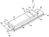
- FIG. 1is a perspective view of an integrated test strip according to one embodiment of the present invention.
- FIG. 1 ais a perspective view of a lancet tip according to another embodiment of the present invention.
- FIG. 2is an exploded view of the FIG. 1 test strip.
- FIG. 3is a cross sectional view of the FIG. 1 lancet during sampling of bodily fluids.
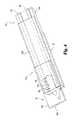
- FIG. 4is a perspective view of an integrated lancing strip according to another embodiment of the present invention.
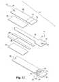
- FIG. 5is an exploded view of the FIG. 4 lancing test strip.
- FIG. 6is a perspective view of an integrated lancing test strip according to another embodiment of the present invention.
- FIG. 7is an exploded view of the FIG. 6 lancet.
- FIG. 8is a top perspective view of an integrated lancing test strip according to a further embodiment of the present invention.
- FIG. 9is a bottom, perspective view of the FIG. 8 lancet.
- FIG. 10is a perspective view of the FIG. 8 lancet mounted in a sampling device.
- FIG. 11is a perspective view of an integrated lancing test strip according to another embodiment of the present invention.
- FIG. 12is an exploded view of the FIG. 11 lancet.
- the present inventiongenerally concerns an integrated skin lancing device that reduces the number of steps involved in collecting and analyzing bodily fluid samples.
- the deviceincludes a lancet for forming an incision in the skin as well as a housing that defines a capillary channel for drawing fluid from the incision onto a test strip located in the housing.
- the devicehas an overall flat shape such that manufacturing of the device is simplified so that its components can be laminated together to form the device. With the integrated design, the user does not have to reposition or reorient a capillary tube or a test strip over the incision in order to draw and analyze a sample.
- one or more spacer membersare sandwiched between a base member and a sheet of flexible, hydrophilic film so as to define the capillary channel with an opening.
- the lancetis attached to the base and has a tip for lancing that extends past the opening of the capillary channel.
- the hydrophilic filmextends past the opening of the capillary channel so as to promote wicking of the bodily fluid sample into the channel. Due to its flexible nature, the hydrophilic film bends against the skin during lancing. After the skin is lanced, the hydrophilic film remains in contact with the skin, and the fluid is drawn via capillary action between the hydrophilic film and the lancet's tip.
- the integrated lancing devicefurther includes a testing means positioned along the capillary channel for analyzing the bodily fluid sample.
- the testing meansincludes a chemical reagent test strip.
- the testing meansin another form includes two or more electrodes that are operatively coupled to an electrochemical reagent test strip.
- the lancetis slidably received inside the capillary channel.
- the lancet in this embodimentis generally flat.
- the lancetis supported and stabilized by the housing throughout the entire lancing stroke so that the lancet remains in proper alignment during lancing.
- the support provided by the housing around the lancetprevents the lancet from laterally deflecting or bending during lancing, which in turn prevents the incision from being formed at the wrong location or angle.
- this designalso allows the flat lancet to be formed from thinner material than previously possible, which in turn may reduce the pain associated with lancing.
- this configurationensures that the capillary channel is positioned directly over the incision.
- the devicefurther includes a retraction mechanism for retracting the lancet into the housing after lancing the skin.
- the lancetextends from the opening of the capillary channel so as to form an incision in the skin.
- the devicehas a skin contacting edge positioned next to the opening of the capillary channel in order to provide a reference surface for flattening the skin around the lancet. By flattening the skin around the lancet, an incision with a precise depth can be formed.
- the deviceincorporates an adjustment mechanism for adjusting the penetration depth of the lancet. Once the skin has been lanced, the retraction mechanism withdraws the lancet back into the housing.
- the bodily fluid from the incisionis then drawn into the channel and around the lancet via capillary action.
- the opening of the capillary channelis positioned over the incision site before lancing. This eliminates the need to reposition the capillary over the incision subsequent to lancing the incision.
- the fluidis then transported to a means for testing the fluid, such as a test strip.
- the number of steps involved in obtaining a sampleis significantly reduced using the integrated device according to the present invention.
- the capillary channel in the integrated devicedoes not have to be repositioned over the incision after lancing. Consequently, the difficulties associated with moving a capillary tube quickly and accurately to the incision site are significantly reduced. It therefore enhances the ability to acquire the expressed body fluid without loss, delay or contamination.
- the devices according to the present inventionare useful for sampling and analyzing various type bodily fluids.
- the devicescan be suitable for sampling either blood or interstitial fluid.
- device 60includes an incision forming member or lancet 62 , a layer of adhesive or adhesive tape 64 , a base 66 , a spacer 68 , a testing area 70 that includes a test strip 72 , a vent member 74 , and a collection sheet or member 76 for drawing a fluid sample into the device 60 .
- Device 60can be used to manually or automatically lance an incision in the skin and analyze the fluid drawn from the incision.
- the lancet 62cuts an incision in the skin such that a droplet of bodily fluid is formed on the skin.
- the collection sheet 76is then used to wick the bodily fluid into a capillary cavity that is defined by the spacer 68 , and the fluid is then deposited on the test strip 72 for analysis.
- other components of device 60that are well know in the art, such has hammers, cocking mechanisms and the like that are not important to appreciate the present invention, will not be discussed below.
- the lancet 62has a generally flat shape such that device 60 has an overall flat shape.
- the lancet 62 as well as the other componentscan be easily formed from sheets of material, such as metal or plastic, and these sheets can be sandwiched together in order to mass produce sampling devices 60 .
- the flat designallows multiple sampling devices 60 to be connected together for use in a cartridge, such as the drum in an ACCU-CHEK® ADVANTAGE® brand meter (Roche Diagnostics Corporation, Indianapolis, Ind.).
- the sampling device 60can also be a stand-alone lancet that is dispensed and used individually.
- the lancet 62is made of metal, in particular stainless steel, but it is contemplated that the lancet 62 can be made of other materials, such as plastic and/or ceramics.
- the lancet 62has a lancet tip or blade 80 extending from a stop edge 82 at one end of the lancet 62 .
- the lancet tip 80 in the illustrated embodimentis sharp such that it is able to cut an incision into the skin, and the stop edge 82 limits the penetration depth of the lancet tip 80 into the skin.
- the lancet tip 80has a generally triangular cross sectional shape. However, it is contemplated that the lancet tip 80 can be shaped differently. For example, FIG.
- 1 ashows a lancet tip 80 a with a slanted shape.
- the lancet 62defines a registration opening 84 that is used to secure and position the device 60 within a bodily fluid testing meter.
- Layer 64is used to secure the lancet 62 to the base 66 .
- layer 64defines a registration opening 86 that is positioned to align with the registration opening 84 in the lancet 62 .
- layer 64is a layer of adhesive, and in another embodiment, layer 64 is a piece of double-sided adhesive tape.
- layer 64can include other types of means for securing components together, such as a weld or the like.
- the lancet 62typically is sterilized.
- the sterilization processcan affect the test strip 72 such that the test strip 72 has to be recalibrated after sterilization.
- the lancet 62 or the test strip 72can be secured to the device 60 after sterilization so as to avoid the undesirable affects of sterilization on the test strip 72 .
- the base 66has a lancet engaging surface 88 to which the lancet 62 is secured and an opposite spacer engaging surface 90 to which spacer 68 is secured.
- the lancet engaging surface 88is coated with the adhesive layer 64 such that the lancet 62 is secured to the base 66 .
- the spacer 68is attached to the base 66 with an adhesive or adhesive tape, but it is contemplated that the spacer 68 can be secured in other manners.
- the base 66can be optional such that the spacer 68 is directly attached to the lancet 62 .
- the base 66defines a notch 92 that is used to reduce the phenomenon called “dose hesitation”.
- dose hesitationincreases the time required in order to collect an adequate sample.
- notch 92the dose hesitation effect is substantially reduced.
- the notch 92 in the illustratedhas a v-shape.
- base 66defines a registration opening 94 that is positioned and sized to align with opening 84 in the lancet 62 .
- openings 84 , 86 and 94form a registration opening 96 in device 60 , as shown in FIG. 1 .
- Registration opening 96is used to position and secure device 60 in a meter.
- the spacer member 68defines a capillary channel or cavity 98 through which fluid is collected.
- the spacer 68is made from a piece of adhesive tape. It should be understood that the spacer 68 can be formed from other materials, such as a bead of adhesive and/or a piece of plastic, to name a few.
- the channel 98has a capillary opening 100 in which the bodily fluid sample is received.
- an end portion 102encloses channel 98 .
- the channel 98is defined by end portion 102 and a pair of arms 104 that extend from portion 102 along the base 66 .
- the spacer 68as well as channel 98 , is sandwiched between base 66 and collection member 76 . Once enclosed, channel 98 is dimensioned so as to draw the bodily fluid sample into the device 60 via capillary action.
- the spacer 68in one embodiment spaces the base 66 and collection sheet 76 apart from one another between two-thousandths of an inch (0.002′′) and ten-thousandths of an inch (0.010′′) to form the capillary channel 98 of that size.
- base 66 and sheet 76are preferably spaced apart between about two-thousandths of an inch (0.002′′) to three-thousandths of an inch (0.002′′) so as to improve the flow rate in the capillary channel 98 .
- the collection member 76is used to draw the fluid sample into the capillary channel 98 via opening 100 .
- collection member 76is in the form of a flexible sheet.
- the sheet 76is able to deform during lancing, and yet is able to contact the skin without closing the incision in order to wick the fluid from the incision into the device 60 .
- sheet 76is a transparent plastic film so as to allow the user to visualize the incision and the droplet of fluid during sampling.
- sheet 76provides a visual indicator such that the user can see whether the device 60 is positioned close enough to collect the fluid.
- the sheet 76can be semi-transparent and/or opaque.
- Sheet 76has a sampling end portion 106 that is configured to contact the skin during sampling. The sampling end portion 106 flexes during collection of fluid so that only a minimal amount of force is applied to the skin such that fluid flow from the incision is not restricted. Sheet 76 further includes a collection end portion 108 that is received between support 78 and test area 70 . Collection end portion 108 isolates the test area 70 from the support 78 so as to enhance fluid flow onto the test strip 72 .
- the flow of fluidmay be enhanced by forming the base 66 , the spacer 68 and/or the sheet 76 along channel 98 from a material which is hydrophilic, which has been treated to be hydrophilic, or which has been coated with a hydrophilic material such as a surfactant or hydrophilic polymers.
- the surfacescan also be treated using polyamides, oxidation (e.g. corona/plasma treatment); plasma chemical vapor deposition; vacuum vapor deposition of metals, metaloxides or non-metaloxides; or deposition of an element which oxidizes with water.
- the entire sheet 76is coated with a layer of aluminum oxide in order to enhance wicking of fluid into the device 60 .
- test strip 72is positioned along capillary channel 98 so that test strip 72 is able to collect fluid drawn into the capillary channel 98 .
- the test strip 72can analyze fluid through such means as optical (e.g., reflectance, absorption, fluorescence, RAMAN, etc.), electrochemical and/or magnetic analysis, to name a few.
- test strip 72is a chemically reactive reagent test strip. It should be appreciated that test strip 72 can analyze fluid in other manners.
- an absorbent padmay be placed between the test strip in the closed end of the capillary channel 98 for wicking body fluid onto the test strip 72 .
- the vent member 74is attached to end portion 102 of the spacer 68 such that a vent opening 110 for channel 98 is defined between the test strip 72 and the vent member 74 .
- the vent opening 110is used to exhaust air or some other gas from the capillary channel 98 , thereby improving the fluid flow in the channel 98 .
- Support 78is attached to sheet 76 so as to act is a support backing for the sheet 76 .
- the support 78is attached to the sheet 76 through an adhesive, and test strip 72 as well as vent member 74 are likewise attached to the spacer 68 through an adhesive. It should be appreciated, however, that these components can be attached to device 60 in other generally known manners.
- the overall, flat design of device 60aids in improving the manufacturability of the device 60 .
- the components of device 60once the components of device 60 are assembled, they form a sampling end at opening 100 from which the lancet tip 80 and sampling end portion 106 of sheet 76 extend.
- the sheet 76 and the lancet tip 80extend in a generally parallel relationship.
- sheet 76may deflect towards or away from tip 80 , depending on the orientation of device 60 .
- a gap 114is formed between sheet 76 and lancet tip 80 for drawing fluid via capillary action.
- sampling end portion 106 of the sheet 76has the same length as tip 80 . In another embodiment, sampling end portion 106 of sheet 76 extends past tip 80 such that sheet 76 can remain in contact with the skin after the lancet tip 80 has been withdrawn from the skin. It is further contemplated that the sampling end portion 106 can be shorter than tip 80 when device 60 is oriented to lance a curved surface (such as a fingertip) or at an angle where sheet 76 can still contact the skin when the lancet tip 80 is removed from the skin.
- sheet 76contacts and bends against skin 116 as the lancet tip 80 is driven towards the skin 116 .
- the lancet tip 80is retracted from the incision 118 so as to allow bodily fluid 120 to flow from the incision 118 .
- the lancet 62can be retracted from the incision 118 either manually by the user, or automatically through a retraction mechanism, such as a spring.
- the device 60is positioned proximal to the skin 116 in order to collect fluid 120 from the incision 118 .
- One of the many benefits of device 60is that positioning of the device 60 for collecting fluid 120 is simplified.
- the device 60does not have to be reoriented or repositioned after lancing in order to collect the fluid 120 .
- sheet 76provides a visual indicator to the user so as to ensure that the device 60 is positioned at the appropriate distance from the skin 116 for drawing fluid 120 from incision 118 .
- the sampling end portion 106 of sheet 76contacts the skin 116 during fluid collection.
- the skin 116tends to deform or dimple, which in turn closes the incision 118 .
- prematurely closing the incision 118the amount of fluid 120 collected on the skin 116 during sampling is significantly reduced.
- sheet 76does not substantially compress skin 116 such that the fluid flow from the incision 118 is not restricted.
- the sheet 76is positioned slightly away from the skin 116 so as to not touch the skin 116 , but is still positioned close enough to draw the fluid 120 from the droplet of fluid 120 .
- sheet 76can be optionally coated or made from a hydrophilic material for enhancing fluid flow along sheet 76 and into the capillary channel 98 . From gap 114 , the fluid 120 is drawn via capillary action into channel 98 , and the fluid 120 from channel 98 is then deposited on the test strip 72 in test area 70 . The fluid 120 can then be analyzed with the test strip 72 in order to determine the desired feature, such as selected analyte levels in the fluid 120 .
- FIGS. 4 and 5An integrated sampling lancet or device 130 according to another embodiment of the present invention is illustrated in FIGS. 4 and 5 .
- the device 130 in the illustrated embodimentis configured to test the bodily fluid sample through electrochemical analysis.
- electrochemical analysis of fluid samplesplease refer to U.S. Pat. No. 6,270,637 to Crismore et al., which is hereby incorporated by reference in its entirety.
- Device 130has many components that are similar to device 60 illustrated in FIGS. 1-3 , with the notable exceptions described below.
- device 130is configured to lance an incision into the skin and draw fluid from the incision into a test area via a flexible sheet.
- device 130has a sampling end portion 132 that is configured to collect a fluid sample and a connection end portion 134 that is adapted to connect to a meter.
- device 130includes an incision forming member or lancet 136 that is used to form an incision in the skin.
- lancet 136has a lancet tip 138 extending from a depth stop edge 140 .
- Tip 138defines a capillary slot 142 that is constructed to draw fluid via capillary action into the device 130 .
- lancet tip 138has a generally triangular shape, but it should be appreciated that in other embodiments, tip 138 can be shaped differently.
- the device 130 in the illustrated embodimenthas an overall flat shape so that device 130 can be easily mass-produced by laminating its various components together.
- the lancet 136is attached to an insulating substrate 144 , which has a blade surface 146 and an electrode surface 148 . As show in FIG. 4 , the lancet 136 is attached to blade surface 146 of the substrate 144 . In one embodiment, blade 136 is attached to the substrate 144 through an adhesive. It should be appreciated, however, that blade 136 can be attached to substrate 144 in other manners. In one particular form, the blade 136 can be attached to the remainder of device 130 after blade 136 has been sterilized. This eliminates the need to recalibrate the device 130 due to the undesirable effects of sterilization. Substrate 144 may be made of any useful insulating material, such as plastic. By way of a nonlimiting example, the insulating substrate 144 can be made of vinyl polymers, polyamides, polyesters, and styrenics in order to provide the electrical and structural properties that are desired.
- the substratehas first 150 and second 152 conductors attached thereto.
- conductors 150 and 152are attached to the substrate 144 with an adhesive and extend in a parallel relationship with respect to one another.
- conductors 150 and 152can be attached in other generally known manners.
- conductors 150 and 152 in the illustrated embodimentextend from the connection end 134 to the sampling end 132 of the device 130 .
- the conductors 150 and 152act as electrodes for analyzing the fluid with the device 130 .
- conductor 150acts as an electrically conductive working electrode and conductor 152 acts as a counter or reference electrode.
- Conductors 150 and 152can be made from electrically conductive materials such as silver, silver chloride and/or palladium, to name a few. In the illustrated embodiments, conductors 150 and 152 are made of palladium. It is contemplated that device 130 can include three or more electrodes. For example, with a three electrode arrangement, a third conductor is placed between conductors 150 and 152 . In this arrangement, the third conductor acts as a reference electrode while conductor 150 acts as a working electrode and conductor 152 acts as a counter electrode. It is further contemplated that in other embodiments the substrate 144 can be optional such that the conductors 150 and 152 can be directly applied to the blade 136 , when blade 136 is made from or coated with an insulating material.
- the device 130includes a test area 154 in which the fluid is analyzed.
- the test area 154includes an electrochemical reagent test strip or coating 156 .
- reagent 156spans between and covers a portion of both conductors 150 and 152 .
- the reagent 156only contacts electrodes 150 and 152 . It is contemplated that reagent 156 may be applied to the entire exposed area of conductors 150 and 152 or may cover only a portion of the exposed portions of conductors 150 and 152 .
- a spacer 158overlays the electrodes 150 and 152 as well as the substrate 144 .
- spacer 158is glued to the substrate 144 , and the spacer 158 is made from an electrically insulative material of the type described above for substrate 144 .
- the spacer 158can be attached to the substrate 144 in other manners.
- conductors 150 and 152are exposed such that the integrated test strip 130 can be operatively coupled to a bodily fluid sampling meter, such as an ACCU-CHEK® COMPACTTM brand meter or an ACCU-CHEK® ADVANTAGE® brand meter (Roche Diagnostics Corporation, Indianapolis, Ind.).
- the spacer 158defines a sampling channel or cavity 160 in which the bodily fluid sample is collected.
- channel 160is sized to form a capillary channel for drawing fluid via capillary action.
- the dimensions of channel 160can be similar to the dimensions given above for the capillary channel 98 in the device 60 illustrated in FIGS. 1-3 .
- channel 160is defined by a pair of spacer arms 162 that extend from spacer 158 .
- the spacer 158further defines an air vent notch 164 that is used in venting air from channel 160 .
- a collection member or sheet 166overlays the sampling channel 160 such that channel 160 is sandwiched between the sheet 166 and the substrate 144 .
- collection member 166is in the form of a flexible sheet.
- sheet 166is a transparent plastic film so as to allow the user to visualize the droplet of fluid at the incision and in the channel 160 during sampling.
- sheet 166provides a visual indicator such that the user can see whether the device 130 is positioned close enough to collect the fluid.
- the sheet 166can be semi-transparent and/or opaque.
- channel 160opens at the sampling end of device 130 .
- an extension portion 168 of sheet 166 as well as lancet tip 138extend from device 130 at end 132 .
- portion 168has the same length as tip 138 .
- portion 168 of sheet 166is longer than tip 138 such that sheet 166 can contact the skin when the lancet tip 138 is withdrawn from the skin. It is further contemplated that portion 168 of sheet 166 can be shorter than the lancet tip 138 in other embodiments.
- the fluid flow in the device 130 of FIGS. 4-5may be enhanced by forming the channel 160 and/or the sheet 166 from a material which is hydrophilic, which has been treated to be hydrophilic, or which has been coated with a hydrophilic material such as a surfactant or hydrophilic polymers.
- the surfacescan also be treated using polyamides, oxidation (e.g. corona/plasma treatment); plasma chemical vapor deposition; vacuum vapor deposition of metals, metaloxides or non-metaloxides; or deposition of an element which oxidizes with water.
- the entire sheet 166 and channel 160are coated with a layer of aluminum oxide in order to enhance wicking of fluid into the channel 160 and promote fluid flow in channel 160 .
- the assembled test strip 130can be used in conjunction with a meter capable of measuring analyte levels of the fluid sample through electrodes 150 and 152 .
- sheet 166bends such that tip 138 is able to form an incision in the skin.
- a droplet of bodily fluidcollects on the surface of the skin.
- the sheet 166is positioned either to contact the skin or positioned proximal to the skin such that fluid is wicked up the sheet 166 and into channel 160 via capillary action. Once a sufficient amount of fluid is collected, the fluid sample can be analyzed in test area 154 using a number of known techniques.
- an integrated sampling device 170has a sampling end portion 172 and an actuation end portion 174 . Similar to the previously described embodiments, device 170 has a capillary channel for drawing a fluid sample onto a test strip in the device. However, in this embodiment, the lancet for forming an incision in the skin is slidably received in the capillary channel. As shown, device 170 in FIGS. 6-7 has a generally flat shape, which makes mass production of device 170 simpler.
- base 176defines a notch 178 in order to reduce dose hesitation and promote collection of bodily fluid.
- base 176is formed from a metallic foil, and the notch 178 is v-shaped.
- Base 176in another embodiment is formed from plastic.
- base 176is formed from a melonex type foil. As should be appreciated, other types of materials may be used to form base 176 .
- a pair of spacer members 180which define a capillary channel 182 , are attached to base 176 .
- spacer member 180are formed from beads of adhesive, and in other embodiment, spacer members 180 are formed from adhesive tape. It should be appreciated that spacer members 180 can be formed from other types of materials.
- channel 182is coated with a hydrophilic material in order to enhance fluid flow in the channel 182 .
- Device 170further includes a lancet or blade member 184 that is slidably received in channel 182 .
- the lancet 184is made from stainless steel, but it is contemplated that lancet 182 can be made from other materials. As shown, the lancet 184 in this embodiment is substantially flat.
- Device 170allows the flat lancet 184 to formed from thinner material than previously possible, which in turn may reduce may reduce the pain associated with lancing.
- the lancetis supported and stabilized by the device 170 throughout most of its length so that the lancet remains in proper alignment during lancing.
- the support provided by the device 170 around the lancet 184prevents the lancet 184 from laterally deflecting or bending during lancing, which in turn prevents the incision from being formed at the wrong location or angle.
- this configurationensures that the capillary channel 182 is positioned directly over the incision.
- lancet 184has a lancet tip 186 that extends from stop edge 188 .
- the lancet tip 186has a generally triangular shape, but it should be appreciated that the lancet tip 186 can have a different shape.
- Device 170further includes a protective tip cover 190 that protects the user from accidentally cutting themselves with the lancet tip 186 and further preserves the sterility of the lancet tip 186 .
- lancet 184includes a head portion 192 that defines a registration opening 194 . The registration opening 194 is used for securing and positioning device 170 in a meter.
- a body portion 196 of the lancet 184is slidably received in channel 182 .
- the head portion 192 of lancet 184is secured to the actuation end portion 174 of the base 176 through an adhesive 198 . Nevertheless, it should be appreciated that lancet 184 can be secured to base 176 in other manners.
- the device 170includes a retraction mechanism 200 .
- the retraction mechanism 200includes a spring arm 202 that is formed by a pair of opposing spring notches 204 and 206 defined in the base 176 .
- movement of the head portion 192 during lancingis stop by the spacer members 180 .
- device 170further incorporates a cover 208 that-encloses the capillary channel 182 .
- the cover 208is secured to spacers 180 , and the cover 208 defines a notch 209 for reducing dose hesitation.
- the cover 208is formed from a melonex type foil. It is contemplated that cover 208 can be formed from other types of materials.
- Device 170further has a vent member 210 attached to the spacers 180 . As shown in FIG. 6 , a test strip or media 212 is attached to the spacers 180 between the cover 208 and the vent member 210 .
- the vent member 210defines a vent opening 214 through which air or some other gas from channel 218 can be exhausted to enhance the fluid flow in channel 182 .
- the test strip 212can be of the type described above, such that it is able to test analyte levels in fluid via electrical, electrochemical, magnetic and/or optical techniques, to name a few.
- the test stripis a chemical reagent test strip.
- device 170can incorporate the collection sheets 76 , 166 of the type described above with reference to FIGS. 1-5 in order to promote wicking of the bodily fluid sample into the capillary channel 182 .
- the sampling end portion 172 of the deviceis pressed against the skin, and the lancet tip 186 is extended from the device 170 in order to cut an incision in the skin.
- Tip 186 of the lancet 184can be manually extended by the user or automatically extended, through a hammer or other means for example.
- the retraction mechanism 202retracts the tip 186 back into the device 170 .
- the sampling end portion 172 of device 170either remains in contact with the skin or is positioned proximal to the droplet of blood such that notches 178 and 209 draw the bodily fluid from the droplet into the capillary channel 182 around the lancet 184 .
- the fluid around the lancet 184is drawn via capillary action onto the test strip 212 . Once deposited on the test strip 212 , the fluid can be analyzed using the bodily fluid analysis techniques described above.
- FIGS. 8-10illustrate a sampling device 330 according to another embodiment of the present invention.
- device 330has a number of features that are common with the embodiments described above, with the notable exceptions discussed below.
- device 330includes a housing 332 , an incision forming member or lancet blade 334 slidably received in the housing 332 , and test media 336 for analyzing the fluid sample.
- the blade 334extends from the housing 332 in order to form an incision in the skin, and fluid from the incision, which is drawn inside the housing 332 around the blade 334 , is deposited onto the test media 336 for analysis.
- device 300incorporates vent member 337 that defines a vent opening between the test media 336 and the vent member 337 for enhancing fluid flow.
- Housing 332has a base 338 and a cover 340 that are attached together through a pair of spacers 342 in order to form a blade cavity 344 in which blade 334 is received.
- both the base 338 and the cover 340are generally flat to give the sampling device 330 an overall flat appearance.
- spacers 342are beads of adhesive that adhere the base 338 and the cover 340 together.
- spacers 342can be formed from other types of materials.
- the housing 332can be further subdivided into separate head 346 and sampling 348 end portions.
- Blade 334is attached to the head 346 and is slidable within blade cavity 344 in the sampling portion 348 of the housing 332 .
- blade cavity 344is sized to draw fluid into the housing 330 via capillary action.
- integrated lancet device 330incorporates a retraction mechanism 349 that retracts the blade 334 inside the housing 332 after lancing.
- the retraction mechanism 349includes a leaf spring 350 defined in base 338 that connects the head 346 to the sampling portion 348 of the housing 332 .
- the head 346can further have notches 352 for securing device 330 to a holder.
- FIGS. 8 and 9illustrate the leaf spring 350 in a flexed state when blade 334 is extended from the housing 332 through opening 353 .
- the base 338 of the housing 332has a skin contacting edge 354 that acts as a reference surface for controlling the penetration depth of the blade 334 during lancing.
- the cover 340has a capillary notch 356 for drawing fluid via capillary action into the blade cavity 344 .
- the capillary notch 356 in the illustrated embodimenthas a gradual tapered shaped from opening 353 to improve fluid flow from the incision into the blade cavity 344 by reducing dose hesitation.
- capillary notch 356 as well as opening 353can be covered with a safety cover 358 that can be used to maintain the sterility of blade 334 and to protect the user from injury.
- test media 336can be of the type described above and can be attached to the housing 332 along cavity 334 in a number of manners.
- the test media 336can be a chemically reactive reagent strip that is glued to the housing.
- the test media 336can be attached to the housing 332 after the blade 334 has been sterilized. Once attached, the test media 334 defines portion of the blade cavity 344 and fluid from slot 356 can be drawn to the test media 332 through the blade cavity 334 .
- vent member 337defines a vent opening along cavity 334 for exhausting air or some other gas out of the blade cavity 334 . It is further contemplated that device 330 can incorporate the collection sheets 76 , 166 of the type described above with reference to FIGS. 1-5 in order to promote wicking of the bodily fluid sample into the blade cavity 344 .
- a holder 360 for device 330 that is operable to adjust the penetration depth of the blade 334is illustrated in FIG. 10 .
- holder 360is incorporated into a fluid sampling meter.
- Holder 360has an enclosure 362 with a receptacle 364 in which device 330 is received and a depth control mechanism 366 that is coupled to the enclosure 362 .
- a test media view window 368is defined in the enclosure 362 such that the test media 336 is able to be viewed for analysis.
- window 368can allow the test media 336 to be analyzed optically.
- window 368can also permit other types of analysis and techniques, such as electrochemical analysis.
- the depth control mechanism 366has a depth adjustment wheel 370 that is rotatably coupled to a bearing member 372 through rod 374 .
- the bearing member 372is attached to the enclosure 362 .
- the rod 374has a gear 376 that is engageable with an actuation gear 378 .
- Wheel 380only partially extends around rod 374 , thereby defining a gap 380 that allows device 330 to be mounted in the holder 360 .
- the wheel 380has a series of steps 382 of graduated thicknesses, and the steps 382 of wheel 380 can be rotated through a slot 384 in the cover 362 .
- the actuation gear 378rotates the wheel 380 such that gap 380 is positioned over the slot 384 .
- Device 330is then slid into the receptacle 364 SO that the head 346 of the device 330 is slid past slot 384 .
- the actuation gear 378rotates the wheel 380 such that at least one of the steps 382 is positioned in the slot 384 between the head 346 and the sampling portion 348 of device 330 , thereby securing the device 330 to the holder 360 .
- the step 382 with the appropriate thicknesscan be positioned in the slot 384 between the head 346 and the skin contacting portion 348 so as to control the penetration depth of the blade 334 .
- the skin contacting edge 354contacts the surface of the skin and flattens the skin around the incision site, thereby providing a suitable surface from which to gage the penetration depth of the blade 334 .
- the skin contacting portion 348 of the housing 332slides within the receptacle 364 towards the head 346 of the device 330 such that the blade 334 is uncovered to lance the skin.
- the skin contacting portion 348 of the housing 332continues to retract until it engages the selected step 382 on the wheel 380 .
- the thickness of the step 382controls the penetration depth of the blade 334 .
- the leaf spring 350which became flexed during lancing, extends portion 348 of the housing 332 so as to recover the blade 334 .
- opening 353 of device 330is positioned proximal the incision in the skin.
- the skin contacting edge 354 of device 330remains in contact with the skin as the drop of fluid forms.
- the skin contacting edge 354is positioned proximal the skin to collect the drop of fluid.
- the fluidis then drawn via capillary action inside the blade cavity 344 . Next, the fluid travels through the blade cavity 344 and is deposited on the test media 336 for analysis.
- an integrated sampling device 470is a variation of the embodiment of device 170 shown in FIGS. 6-7 . Similar to previously described embodiments device 470 has a capillary channel 182 for drawing a fluid sample. Device 470 additionally incorporates a cover 408 that extends beyond base 176 at the sampling end portion 172 . This arrangement allows the sampling end portion 172 to be pushed into the skin surrounding an incision with no ill effect. The uneven lengths of the cover 408 and base 176 create a bevel that applies the pushing force into the skin asymmetrically around the incision tending to keep the incision open. Alternatively, base 176 could extend beyond cover 408 to achieve the same benefit.
- Device 470additionally incorporates collection sheets 466 and 467 on opposite sides of a pair of spacer members 480 .
- Sheet 466is positioned between the cover 408 and the spacer members 480 .
- Sheet 467is positioned between the spacer members 480 and the base 176 .
- the pair of spacer members 480 and collection sheets 466 and 467define a capillary channel 182 .
- Device 470further includes a lancet 184 that is slidably received in channel 182 .
- Collection sheets 466 and 467have the same properties and characteristics previously described collection members or sheets 76 and 166 . As shown in FIGS. 11 and 12 , sheets 466 and 467 face each other and are separated by spacer members 480 . Collection sheets 466 and 467 extend beyond cover 408 and base 176 to facilitate drawing body fluid into the capillary channel 182 without closing the incision. By incorporating multiple collection sheets 466 and 467 , device 470 collects fluid over a larger area without having to be moved. It is further contemplated that device 470 incorporates only a single sheet, either sheet 466 or sheet 467 . It is further contemplated that sheets 466 and 467 have the same or shorter length as base cover 408 and base 176 .
- Device 470operates similarly to the previously described operation of device 170 . The differences in operation arise after the incision is formed. An incision is formed as previously described with device 170 . After the incision is formed, the sampling end portion 172 of device 470 remains in contact with the skin or is positioned above the fluid such that collection sheets 466 and 467 are in contact with the fluid. Collection sheets 466 and 467 draw the fluid from the incision into the capillary channel 182 .
- the bodily fluidmay be collected in the capillary channel 182 . Alternatively, the bodily fluid may be drawn by capillary action onto the test strip 212 . Once deposited on the test strip 212 , the fluid can be analyzed using the bodily fluid techniques described above.
Landscapes
- Health & Medical Sciences (AREA)
- Life Sciences & Earth Sciences (AREA)
- Physics & Mathematics (AREA)
- Engineering & Computer Science (AREA)
- Medical Informatics (AREA)
- Animal Behavior & Ethology (AREA)
- Pathology (AREA)
- Veterinary Medicine (AREA)
- Biomedical Technology (AREA)
- Heart & Thoracic Surgery (AREA)
- Public Health (AREA)
- Molecular Biology (AREA)
- Surgery (AREA)
- Biophysics (AREA)
- General Health & Medical Sciences (AREA)
- Hematology (AREA)
- Emergency Medicine (AREA)
- Optics & Photonics (AREA)
- Manufacturing & Machinery (AREA)
- Dermatology (AREA)
- Measurement Of The Respiration, Hearing Ability, Form, And Blood Characteristics Of Living Organisms (AREA)
Abstract
Description
Claims (48)
Priority Applications (1)
| Application Number | Priority Date | Filing Date | Title |
|---|---|---|---|
| US10/767,522US7374546B2 (en) | 2003-01-29 | 2004-01-29 | Integrated lancing test strip |
Applications Claiming Priority (2)
| Application Number | Priority Date | Filing Date | Title |
|---|---|---|---|
| US44332803P | 2003-01-29 | 2003-01-29 | |
| US10/767,522US7374546B2 (en) | 2003-01-29 | 2004-01-29 | Integrated lancing test strip |
Publications (2)
| Publication Number | Publication Date |
|---|---|
| US20040186394A1 US20040186394A1 (en) | 2004-09-23 |
| US7374546B2true US7374546B2 (en) | 2008-05-20 |
Family
ID=32825321
Family Applications (1)
| Application Number | Title | Priority Date | Filing Date |
|---|---|---|---|
| US10/767,522Active2025-12-20US7374546B2 (en) | 2003-01-29 | 2004-01-29 | Integrated lancing test strip |
Country Status (4)
| Country | Link |
|---|---|
| US (1) | US7374546B2 (en) |
| EP (1) | EP1589873B1 (en) |
| AT (1) | ATE537752T1 (en) |
| WO (1) | WO2004066822A2 (en) |
Cited By (58)
| Publication number | Priority date | Publication date | Assignee | Title |
|---|---|---|---|---|
| US20060166302A1 (en)* | 2005-01-27 | 2006-07-27 | Raman Systems, Inc. | Handheld raman blood analyzer |
| US20060196031A1 (en)* | 2003-04-04 | 2006-09-07 | Joachim Hoenes | Method for producing a puncturing and measuring device |
| US20060240401A1 (en)* | 2005-01-27 | 2006-10-26 | Clarke Richard H | Handheld raman body fluid analyzer |
| US20100056893A1 (en)* | 2006-09-04 | 2010-03-04 | Hans List | Medical aid |
| US7688440B2 (en) | 2005-01-27 | 2010-03-30 | Prescient Medical, Inc. | Raman spectroscopic test strip systems |
| US7875047B2 (en) | 2002-04-19 | 2011-01-25 | Pelikan Technologies, Inc. | Method and apparatus for a multi-use body fluid sampling device with sterility barrier release |
| US7892183B2 (en) | 2002-04-19 | 2011-02-22 | Pelikan Technologies, Inc. | Method and apparatus for body fluid sampling and analyte sensing |
| US7901365B2 (en) | 2002-04-19 | 2011-03-08 | Pelikan Technologies, Inc. | Method and apparatus for penetrating tissue |
| US7909778B2 (en) | 2002-04-19 | 2011-03-22 | Pelikan Technologies, Inc. | Method and apparatus for penetrating tissue |
| US7909777B2 (en) | 2002-04-19 | 2011-03-22 | Pelikan Technologies, Inc | Method and apparatus for penetrating tissue |
| US7909775B2 (en) | 2001-06-12 | 2011-03-22 | Pelikan Technologies, Inc. | Method and apparatus for lancet launching device integrated onto a blood-sampling cartridge |
| US7909774B2 (en) | 2002-04-19 | 2011-03-22 | Pelikan Technologies, Inc. | Method and apparatus for penetrating tissue |
| US7914465B2 (en) | 2002-04-19 | 2011-03-29 | Pelikan Technologies, Inc. | Method and apparatus for penetrating tissue |
| US7976476B2 (en) | 2002-04-19 | 2011-07-12 | Pelikan Technologies, Inc. | Device and method for variable speed lancet |
| US7981055B2 (en) | 2001-06-12 | 2011-07-19 | Pelikan Technologies, Inc. | Tissue penetration device |
| US7981056B2 (en) | 2002-04-19 | 2011-07-19 | Pelikan Technologies, Inc. | Methods and apparatus for lancet actuation |
| US7988645B2 (en) | 2001-06-12 | 2011-08-02 | Pelikan Technologies, Inc. | Self optimizing lancing device with adaptation means to temporal variations in cutaneous properties |
| US8007446B2 (en) | 2002-04-19 | 2011-08-30 | Pelikan Technologies, Inc. | Method and apparatus for penetrating tissue |
| US8062231B2 (en) | 2002-04-19 | 2011-11-22 | Pelikan Technologies, Inc. | Method and apparatus for penetrating tissue |
| US8079960B2 (en) | 2002-04-19 | 2011-12-20 | Pelikan Technologies, Inc. | Methods and apparatus for lancet actuation |
| US8197421B2 (en) | 2002-04-19 | 2012-06-12 | Pelikan Technologies, Inc. | Method and apparatus for penetrating tissue |
| US8221334B2 (en) | 2002-04-19 | 2012-07-17 | Sanofi-Aventis Deutschland Gmbh | Method and apparatus for penetrating tissue |
| US8251921B2 (en) | 2003-06-06 | 2012-08-28 | Sanofi-Aventis Deutschland Gmbh | Method and apparatus for body fluid sampling and analyte sensing |
| US8262614B2 (en) | 2003-05-30 | 2012-09-11 | Pelikan Technologies, Inc. | Method and apparatus for fluid injection |
| US8267870B2 (en) | 2002-04-19 | 2012-09-18 | Sanofi-Aventis Deutschland Gmbh | Method and apparatus for body fluid sampling with hybrid actuation |
| US8282576B2 (en) | 2003-09-29 | 2012-10-09 | Sanofi-Aventis Deutschland Gmbh | Method and apparatus for an improved sample capture device |
| US8296918B2 (en) | 2003-12-31 | 2012-10-30 | Sanofi-Aventis Deutschland Gmbh | Method of manufacturing a fluid sampling device with improved analyte detecting member configuration |
| US8333710B2 (en) | 2002-04-19 | 2012-12-18 | Sanofi-Aventis Deutschland Gmbh | Tissue penetration device |
| US8360992B2 (en) | 2002-04-19 | 2013-01-29 | Sanofi-Aventis Deutschland Gmbh | Method and apparatus for penetrating tissue |
| US8372016B2 (en) | 2002-04-19 | 2013-02-12 | Sanofi-Aventis Deutschland Gmbh | Method and apparatus for body fluid sampling and analyte sensing |
| US8382682B2 (en) | 2002-04-19 | 2013-02-26 | Sanofi-Aventis Deutschland Gmbh | Method and apparatus for penetrating tissue |
| US8435190B2 (en) | 2002-04-19 | 2013-05-07 | Sanofi-Aventis Deutschland Gmbh | Method and apparatus for penetrating tissue |
| US8439872B2 (en) | 1998-03-30 | 2013-05-14 | Sanofi-Aventis Deutschland Gmbh | Apparatus and method for penetration with shaft having a sensor for sensing penetration depth |
| US8556829B2 (en) | 2002-04-19 | 2013-10-15 | Sanofi-Aventis Deutschland Gmbh | Method and apparatus for penetrating tissue |
| US8574895B2 (en) | 2002-12-30 | 2013-11-05 | Sanofi-Aventis Deutschland Gmbh | Method and apparatus using optical techniques to measure analyte levels |
| US8641644B2 (en) | 2000-11-21 | 2014-02-04 | Sanofi-Aventis Deutschland Gmbh | Blood testing apparatus having a rotatable cartridge with multiple lancing elements and testing means |
| US8652831B2 (en) | 2004-12-30 | 2014-02-18 | Sanofi-Aventis Deutschland Gmbh | Method and apparatus for analyte measurement test time |
| US8668656B2 (en) | 2003-12-31 | 2014-03-11 | Sanofi-Aventis Deutschland Gmbh | Method and apparatus for improving fluidic flow and sample capture |
| US8702624B2 (en) | 2006-09-29 | 2014-04-22 | Sanofi-Aventis Deutschland Gmbh | Analyte measurement device with a single shot actuator |
| US8721671B2 (en) | 2001-06-12 | 2014-05-13 | Sanofi-Aventis Deutschland Gmbh | Electric lancet actuator |
| US8784335B2 (en) | 2002-04-19 | 2014-07-22 | Sanofi-Aventis Deutschland Gmbh | Body fluid sampling device with a capacitive sensor |
| US8828203B2 (en) | 2004-05-20 | 2014-09-09 | Sanofi-Aventis Deutschland Gmbh | Printable hydrogels for biosensors |
| US8965476B2 (en) | 2010-04-16 | 2015-02-24 | Sanofi-Aventis Deutschland Gmbh | Tissue penetration device |
| US9144401B2 (en) | 2003-06-11 | 2015-09-29 | Sanofi-Aventis Deutschland Gmbh | Low pain penetrating member |
| US9226699B2 (en) | 2002-04-19 | 2016-01-05 | Sanofi-Aventis Deutschland Gmbh | Body fluid sampling module with a continuous compression tissue interface surface |
| US9248267B2 (en) | 2002-04-19 | 2016-02-02 | Sanofi-Aventis Deustchland Gmbh | Tissue penetration device |
| US9314194B2 (en) | 2002-04-19 | 2016-04-19 | Sanofi-Aventis Deutschland Gmbh | Tissue penetration device |
| US9351680B2 (en) | 2003-10-14 | 2016-05-31 | Sanofi-Aventis Deutschland Gmbh | Method and apparatus for a variable user interface |
| US9375169B2 (en) | 2009-01-30 | 2016-06-28 | Sanofi-Aventis Deutschland Gmbh | Cam drive for managing disposable penetrating member actions with a single motor and motor and control system |
| US9386944B2 (en) | 2008-04-11 | 2016-07-12 | Sanofi-Aventis Deutschland Gmbh | Method and apparatus for analyte detecting device |
| US9427532B2 (en) | 2001-06-12 | 2016-08-30 | Sanofi-Aventis Deutschland Gmbh | Tissue penetration device |
| TWI568417B (en)* | 2014-12-01 | 2017-02-01 | 國竤工業有限公司 | Biochemical reaction cartridge |
| US9775553B2 (en) | 2004-06-03 | 2017-10-03 | Sanofi-Aventis Deutschland Gmbh | Method and apparatus for a fluid sampling device |
| US9795747B2 (en) | 2010-06-02 | 2017-10-24 | Sanofi-Aventis Deutschland Gmbh | Methods and apparatus for lancet actuation |
| US9820684B2 (en) | 2004-06-03 | 2017-11-21 | Sanofi-Aventis Deutschland Gmbh | Method and apparatus for a fluid sampling device |
| US10154809B2 (en) | 2015-06-24 | 2018-12-18 | University Of Virginia Patent Foundation | Test strip device and related methods thereof |
| US10638963B2 (en) | 2017-01-10 | 2020-05-05 | Drawbridge Health, Inc. | Devices, systems, and methods for sample collection |
| US11266337B2 (en) | 2015-09-09 | 2022-03-08 | Drawbridge Health, Inc. | Systems, methods, and devices for sample collection, stabilization and preservation |
Families Citing this family (88)
| Publication number | Priority date | Publication date | Assignee | Title |
|---|---|---|---|---|
| US6036924A (en) | 1997-12-04 | 2000-03-14 | Hewlett-Packard Company | Cassette of lancet cartridges for sampling blood |
| US7310543B2 (en)* | 2001-03-26 | 2007-12-18 | Kumetrix, Inc. | Silicon microprobe with integrated biosensor |
| US7476533B2 (en) | 2002-04-19 | 2009-01-13 | Adhesives Research, Inc. | Diagnostic devices for use in the assaying of biological fluids |
| AU2002344825A1 (en) | 2001-06-12 | 2002-12-23 | Pelikan Technologies, Inc. | Method and apparatus for improving success rate of blood yield from a fingerstick |
| JP4272051B2 (en) | 2001-06-12 | 2009-06-03 | ペリカン テクノロジーズ インコーポレイテッド | Blood sampling apparatus and method |
| WO2002101359A2 (en) | 2001-06-12 | 2002-12-19 | Pelikan Technologies, Inc. | Integrated blood sampling analysis system with multi-use sampling module |
| DE10134650B4 (en)* | 2001-07-20 | 2009-12-03 | Roche Diagnostics Gmbh | System for taking small amounts of body fluid |
| US7344894B2 (en) | 2001-10-16 | 2008-03-18 | Agilent Technologies, Inc. | Thermal regulation of fluidic samples within a diagnostic cartridge |
| US7004928B2 (en) | 2002-02-08 | 2006-02-28 | Rosedale Medical, Inc. | Autonomous, ambulatory analyte monitor or drug delivery device |
| US7244265B2 (en) | 2002-04-19 | 2007-07-17 | Pelikan Technologies, Inc. | Method and apparatus for penetrating tissue |
| US7648468B2 (en) | 2002-04-19 | 2010-01-19 | Pelikon Technologies, Inc. | Method and apparatus for penetrating tissue |
| WO2003088824A2 (en) | 2002-04-19 | 2003-10-30 | Pelikan Technologies, Inc. | Device and method for variable speed lancet |
| US7410468B2 (en) | 2002-04-19 | 2008-08-12 | Pelikan Technologies, Inc. | Method and apparatus for penetrating tissue |
| US7717863B2 (en) | 2002-04-19 | 2010-05-18 | Pelikan Technologies, Inc. | Method and apparatus for penetrating tissue |
| US7485128B2 (en) | 2002-04-19 | 2009-02-03 | Pelikan Technologies, Inc. | Method and apparatus for penetrating tissue |
| US7291117B2 (en) | 2002-04-19 | 2007-11-06 | Pelikan Technologies, Inc. | Method and apparatus for penetrating tissue |
| US7374544B2 (en) | 2002-04-19 | 2008-05-20 | Pelikan Technologies, Inc. | Method and apparatus for penetrating tissue |
| US7141058B2 (en) | 2002-04-19 | 2006-11-28 | Pelikan Technologies, Inc. | Method and apparatus for a body fluid sampling device using illumination |
| US7524293B2 (en) | 2002-04-19 | 2009-04-28 | Pelikan Technologies, Inc. | Method and apparatus for penetrating tissue |
| US7563232B2 (en) | 2002-04-19 | 2009-07-21 | Pelikan Technologies, Inc. | Method and apparatus for penetrating tissue |
| US7371247B2 (en) | 2002-04-19 | 2008-05-13 | Pelikan Technologies, Inc | Method and apparatus for penetrating tissue |
| US7481777B2 (en)* | 2006-01-05 | 2009-01-27 | Roche Diagnostics Operations, Inc. | Lancet integrated test element tape dispenser |
| US8052926B2 (en)* | 2002-12-27 | 2011-11-08 | Roche Diagnostics Operations, Inc. | Method for manufacturing a sterilized lancet integrated biosensor |
| US7815579B2 (en) | 2005-03-02 | 2010-10-19 | Roche Diagnostics Operations, Inc. | Dynamic integrated lancing test strip with sterility cover |
| US7211052B2 (en)* | 2002-12-30 | 2007-05-01 | Roche Diagnostics Operations, Inc. | Flexible test strip lancet device |
| US7214200B2 (en)* | 2002-12-30 | 2007-05-08 | Roche Diagnostics Operations, Inc. | Integrated analytical test element |
| US7052652B2 (en) | 2003-03-24 | 2006-05-30 | Rosedale Medical, Inc. | Analyte concentration detection devices and methods |
| EP1635700B1 (en) | 2003-06-13 | 2016-03-09 | Sanofi-Aventis Deutschland GmbH | Apparatus for a point of care device |
| US8071030B2 (en) | 2003-06-20 | 2011-12-06 | Roche Diagnostics Operations, Inc. | Test strip with flared sample receiving chamber |
| JP4447009B2 (en) | 2003-06-20 | 2010-04-07 | エフ ホフマン−ラ ロッシュ アクチェン ゲゼルシャフト | Test strip with slot vent opening |
| US8679853B2 (en) | 2003-06-20 | 2014-03-25 | Roche Diagnostics Operations, Inc. | Biosensor with laser-sealed capillary space and method of making |
| US7867369B2 (en)* | 2003-06-20 | 2011-01-11 | Roche Diagnostics Operations, Inc. | Biosensor with multiple electrical functionalities |
| JP4334969B2 (en)* | 2003-10-02 | 2009-09-30 | パナソニック株式会社 | Blood component analysis sensor |
| US8394341B2 (en)* | 2004-03-08 | 2013-03-12 | Agilent Technologies, Inc. | Microfluidic chip frame |
| EP1737345A1 (en)* | 2004-04-15 | 2007-01-03 | Roche Diagnostics GmbH | Integrated spot monitoring device with fluid sensor |
| US7322942B2 (en)* | 2004-05-07 | 2008-01-29 | Roche Diagnostics Operations, Inc. | Integrated disposable for automatic or manual blood dosing |
| US7766845B2 (en)* | 2004-06-21 | 2010-08-03 | Roche Diagnostics Operations, Inc. | Disposable lancet and lancing cap combination for increased hygiene |
| US20060036187A1 (en)* | 2004-06-30 | 2006-02-16 | Hester Vos | Devices, systems and methods for extracting bodily fluid and monitoring an analyte therein |
| US7727166B2 (en)* | 2004-07-26 | 2010-06-01 | Nova Biomedical Corporation | Lancet, lancet assembly and lancet-sensor combination |
| GB0420256D0 (en) | 2004-09-13 | 2004-10-13 | Cassells John M | Method and apparatus for sampling and analysis of fluids |
| US7488298B2 (en)* | 2004-10-08 | 2009-02-10 | Roche Diagnostics Operations, Inc. | Integrated lancing test strip with capillary transfer sheet |
| US7935063B2 (en)* | 2005-03-02 | 2011-05-03 | Roche Diagnostics Operations, Inc. | System and method for breaking a sterility seal to engage a lancet |
| US7695442B2 (en) | 2005-04-12 | 2010-04-13 | Roche Diagnostics Operations, Inc. | Integrated lancing test strip with retractable lancet |
| US7955271B2 (en) | 2006-10-13 | 2011-06-07 | Roche Diagnostics Operations, Inc. | Tape transport lance sampler |
| EP1868491B1 (en) | 2005-03-24 | 2011-05-18 | Roche Diagnostics GmbH | Analyzing means with lancet and test element |
| US20060281187A1 (en) | 2005-06-13 | 2006-12-14 | Rosedale Medical, Inc. | Analyte detection devices and methods with hematocrit/volume correction and feedback control |
| US8636672B2 (en)* | 2007-02-28 | 2014-01-28 | Nipro Diagnostics, Inc. | Test strip with integrated lancet |
| US20100081968A1 (en)* | 2005-07-15 | 2010-04-01 | Home Diagnostics, Inc. | Test Strip With Integrated Lancet |
| US7775991B2 (en)* | 2005-08-31 | 2010-08-17 | Kimberly-Clark Worldwide, Inc. | Device for sampling blood |
| EP1759633A1 (en)* | 2005-09-01 | 2007-03-07 | F.Hoffmann-La Roche Ag | Device for sampling bodily fluids and its fabrication method |
| EP1928302B1 (en) | 2005-09-30 | 2012-08-01 | Intuity Medical, Inc. | Fully integrated wearable or handheld monitor |
| US8801631B2 (en)* | 2005-09-30 | 2014-08-12 | Intuity Medical, Inc. | Devices and methods for facilitating fluid transport |
| US8057404B2 (en)* | 2005-10-12 | 2011-11-15 | Panasonic Corporation | Blood sensor, blood testing apparatus, and method for controlling blood testing apparatus |
| EP1785090A1 (en)* | 2005-11-10 | 2007-05-16 | F.Hoffmann-La Roche Ag | Lancet device and system for skin detection |
| US8353848B2 (en)* | 2005-11-21 | 2013-01-15 | Alere Switzerland Gmbh | Test device |
| WO2007092173A2 (en)* | 2006-02-06 | 2007-08-16 | Prescient Medical, Inc. | Raman spectroscopic lateral flow test strip assays |
| EP1818014A1 (en) | 2006-02-09 | 2007-08-15 | F. Hoffmann-la Roche AG | Test element with elastically supported lancet |
| US20090299225A1 (en)* | 2006-04-17 | 2009-12-03 | Sumitomo Electric Industries, Ltd. | Biosensor chip |
| CA2659075A1 (en)* | 2006-06-23 | 2007-12-27 | F. Hoffmann-La Roche Ag | Packaging system |
| GB0617035D0 (en)* | 2006-08-30 | 2006-10-11 | Inverness Medical Switzerland | Fluidic indicator device |
| US8852124B2 (en)* | 2006-10-13 | 2014-10-07 | Roche Diagnostics Operations, Inc. | Tape transport lance sampler |
| US8052618B2 (en)* | 2006-10-15 | 2011-11-08 | Roche Diagnostics Operations, Inc. | Diagnostic test element and process for its production |
| EP2090227A4 (en)* | 2006-11-10 | 2010-01-27 | Nat Inst Of Advanced Ind Scien | BIODELECTOR CARTRIDGE, BIOSENSOR DEVICE, SPECIMEN SAMPLING METHOD, METHOD FOR MANUFACTURING BIOSENSOR CARTRIDGE, AND INTEGRATED NEEDLE SENSOR |
| USD587142S1 (en) | 2006-12-22 | 2009-02-24 | Abbott Diabetes Care Inc. | Sensors |
| US7802467B2 (en) | 2006-12-22 | 2010-09-28 | Abbott Diabetes Care Inc. | Analyte sensors and methods of use |
| JP2008167942A (en)* | 2007-01-11 | 2008-07-24 | National Institute Of Advanced Industrial & Technology | Biosensor cartridge |
| WO2008105373A1 (en)* | 2007-02-26 | 2008-09-04 | National Institute Of Advanced Industrial Science And Technology | Sensor device |
| EP2163200A4 (en)* | 2007-07-11 | 2010-12-01 | Nitto Denko Corp | Body fluid collecting circuit board |
| US9833183B2 (en) | 2008-05-30 | 2017-12-05 | Intuity Medical, Inc. | Body fluid sampling device—sampling site interface |
| EP3984454A1 (en) | 2008-06-06 | 2022-04-20 | Intuity Medical, Inc. | Medical diagnostic devices and methods |
| WO2009148624A1 (en) | 2008-06-06 | 2009-12-10 | Intuity Medical, Inc. | Detection meter and mode of operation |
| EP2316339A4 (en)* | 2008-08-01 | 2012-10-24 | Lightnix Inc | Sensor with fine needle having channel formed therein |
| JP2012504233A (en)* | 2008-09-30 | 2012-02-16 | メナイ メディカル テクノロジーズ リミテッド | Sample measurement system |
| CA2746128C (en) | 2009-01-30 | 2020-07-28 | Pronota N.V. | Biomarker for diagnosis, prediction and/or prognosis of acute heart failure and uses thereof |
| US20110040208A1 (en)* | 2009-08-11 | 2011-02-17 | Abbott Diabetes Care Inc. | Integrated lancet and test strip and methods of making and using same |
| US8628979B2 (en) | 2009-10-21 | 2014-01-14 | Pronota N.V. | MCAM as a biomarker for fluid homeostasis |
| EP2506768B1 (en) | 2009-11-30 | 2016-07-06 | Intuity Medical, Inc. | Calibration material delivery devices and methods |
| EP2924439B1 (en) | 2010-03-26 | 2017-02-01 | MyCartis N.V. | Ltbp2 as a biomarker for predicting or prognosticating mortality |
| GB201005359D0 (en) | 2010-03-30 | 2010-05-12 | Menai Medical Technologies Ltd | Sampling plate |
| GB201005357D0 (en) | 2010-03-30 | 2010-05-12 | Menai Medical Technologies Ltd | Sampling plate |
| AU2011240039B2 (en) | 2010-04-13 | 2017-01-19 | Mycartis Nv | Biomarkers for hypertensive disorders of pregnancy |
| CA2803797A1 (en) | 2010-06-25 | 2011-12-29 | Intuity Medical, Inc. | Analyte monitoring methods and systems |
| US9782114B2 (en) | 2011-08-03 | 2017-10-10 | Intuity Medical, Inc. | Devices and methods for body fluid sampling and analysis |
| US9192375B2 (en) | 2012-02-29 | 2015-11-24 | Marker Medical, Llc | Surgical apparatus and method |
| WO2014205412A1 (en) | 2013-06-21 | 2014-12-24 | Intuity Medical, Inc. | Analyte monitoring system with audible feedback |
| USD849265S1 (en)* | 2017-04-21 | 2019-05-21 | Precision Nanosystems Inc | Microfluidic chip |
| EP3859316A1 (en)* | 2020-01-31 | 2021-08-04 | Midge Medical GmbH | Testing device for lateral flow assay |
| CN111529015A (en)* | 2020-06-12 | 2020-08-14 | 镁格生物科技(江苏)有限公司 | Puncture outfit and sleeve thereof |
Citations (92)
| Publication number | Priority date | Publication date | Assignee | Title |
|---|---|---|---|---|
| US1328459A (en) | 1918-10-18 | 1920-01-20 | Arthur E Smith | Instrument for producing intra-osseous anesthesia |
| US2359550A (en) | 1942-07-07 | 1944-10-03 | Salsbury S Lab Dr | Fowl vaccinator |
| US2646799A (en) | 1951-02-14 | 1953-07-28 | Jr George W Jacoby | Blood lancet |
| US2801633A (en) | 1954-02-17 | 1957-08-06 | Joseph C Ehrlich | Lancets |
| US3802842A (en) | 1971-04-16 | 1974-04-09 | Boehringer Mannheim Gmbh | Test strips |
| US4061468A (en) | 1974-07-30 | 1977-12-06 | Boehringer Mannheim Gmbh | Stable test strips having a water-soluble paper layer and methods for making same |
| US4095589A (en)* | 1975-05-20 | 1978-06-20 | Plastronics, Inc. | Combination urine meter and drainage receptacle |
| USD254444S (en) | 1977-09-01 | 1980-03-11 | Levine Robert A | Blood sampling needle |
| US4203446A (en) | 1976-09-24 | 1980-05-20 | Hellige Gmbh | Precision spring lancet |
| US4360016A (en) | 1980-07-01 | 1982-11-23 | Transidyne General Corp. | Blood collecting device |
| US4375815A (en) | 1981-03-23 | 1983-03-08 | Becton Dickinson And Company | Retractable lancet assembly |
| US4462405A (en) | 1982-09-27 | 1984-07-31 | Ehrlich Joseph C | Blood letting apparatus |
| US4469110A (en) | 1981-06-25 | 1984-09-04 | Slama Gerard J | Device for causing a pinprick to obtain and to test a drop of blood |
| US4490465A (en) | 1982-03-26 | 1984-12-25 | Merck Patent Gesellschaft Mit Beschrankter Haftung | Coupled enzyme systems for determination of dissolved substances |
| US4627445A (en) | 1985-04-08 | 1986-12-09 | Garid, Inc. | Glucose medical monitoring system |
| US4653513A (en) | 1985-08-09 | 1987-03-31 | Dombrowski Mitchell P | Blood sampler |
| US4677979A (en) | 1984-09-20 | 1987-07-07 | Becton, Dickinson And Company | Lancet |
| US4787398A (en) | 1985-04-08 | 1988-11-29 | Garid, Inc. | Glucose medical monitoring system |
| US4869249A (en) | 1987-05-01 | 1989-09-26 | Owen Mumford Limited | Blood sampling devices |
| US4895147A (en) | 1988-10-28 | 1990-01-23 | Sherwood Medical Company | Lancet injector |
| US4924879A (en) | 1988-10-07 | 1990-05-15 | Brien Walter J O | Blood lancet device |
| US4990154A (en) | 1989-06-19 | 1991-02-05 | Miles Inc. | Lancet assembly |
| US5100391A (en) | 1990-04-03 | 1992-03-31 | Schutte Michael J | Double-bladed scalpel |
| WO1993009710A1 (en) | 1991-11-20 | 1993-05-27 | Habley Medical Technology Corporation | Blood sampler and component tester |
| WO1993009723A1 (en) | 1991-11-12 | 1993-05-27 | Ramel Urs A | Lancet device |
| EP0582276A1 (en) | 1992-08-03 | 1994-02-09 | United States Surgical Corporation | Needles made from non-round stock |
| US5304193A (en) | 1993-08-12 | 1994-04-19 | Sam Zhadanov | Blood lancing device |
| US5423847A (en) | 1992-09-25 | 1995-06-13 | Amg Medical, Inc. | Safe lancet injector |
| US5529581A (en) | 1994-05-17 | 1996-06-25 | International Technidyne Corporation | Lancet device for creating a skin incision |
| US5545173A (en) | 1993-06-02 | 1996-08-13 | Herbst; Richard | Apparatus for taking blood samples |
| US5582184A (en)* | 1993-10-13 | 1996-12-10 | Integ Incorporated | Interstitial fluid collection and constituent measurement |
| US5607401A (en) | 1991-09-03 | 1997-03-04 | Humphrey; Bruce H. | Augmented polymeric hypodermic devices |
| US5607437A (en) | 1990-07-12 | 1997-03-04 | University Of Miami | Instruments for use in performing gel injection adjustable keratoplasty |
| US5613978A (en) | 1996-06-04 | 1997-03-25 | Palco Laboratories | Adjustable tip for lancet device |
| US5628764A (en) | 1995-03-21 | 1997-05-13 | Schraga; Steven | Collar lancet device |
| US5628765A (en) | 1994-11-29 | 1997-05-13 | Apls Co., Ltd. | Lancet assembly |
| US5730753A (en) | 1995-07-28 | 1998-03-24 | Apls Co., Ltd. | Assembly for adjusting pricking depth of lancet |
| USRE35803E (en) | 1992-04-13 | 1998-05-19 | Boehringer Mannheim Gmbh | Blood lancet device for and method withdrawing blood for diagnostic purposes |
| US5776719A (en) | 1997-07-07 | 1998-07-07 | Mercury Diagnostics, Inc. | Diagnostic compositions and devices utilizing same |
| US5798031A (en) | 1997-05-12 | 1998-08-25 | Bayer Corporation | Electrochemical biosensor |
| US5824491A (en) | 1996-05-17 | 1998-10-20 | Mercury Diagnostics, Inc. | Dry reagent test strip comprising benzidine dye precursor and antipyrine compound |
| US5830225A (en) | 1996-08-19 | 1998-11-03 | Detsch; Steven G. | Dental and medical tissue knife |
| US5857983A (en) | 1996-05-17 | 1999-01-12 | Mercury Diagnostics, Inc. | Methods and apparatus for sampling body fluid |
| US5871494A (en) | 1997-12-04 | 1999-02-16 | Hewlett-Packard Company | Reproducible lancing for sampling blood |
| US5873887A (en) | 1996-10-25 | 1999-02-23 | Bayer Corporation | Blood sampling device |
| US5879311A (en) | 1996-05-17 | 1999-03-09 | Mercury Diagnostics, Inc. | Body fluid sampling device and methods of use |
| DE19753847A1 (en) | 1997-12-04 | 1999-06-10 | Roche Diagnostics Gmbh | Analytical test element with capillary channel |
| US5916230A (en) | 1997-06-16 | 1999-06-29 | Bayer Corporation | Blood sampling device with adjustable end cap |
| US5951493A (en) | 1997-05-16 | 1999-09-14 | Mercury Diagnostics, Inc. | Methods and apparatus for expressing body fluid from an incision |
| US5951492A (en) | 1996-05-17 | 1999-09-14 | Mercury Diagnostics, Inc. | Methods and apparatus for sampling and analyzing body fluid |
| US5962215A (en) | 1996-04-05 | 1999-10-05 | Mercury Diagnostics, Inc. | Methods for testing the concentration of an analyte in a body fluid |
| US5964718A (en) | 1997-11-21 | 1999-10-12 | Mercury Diagnostics, Inc. | Body fluid sampling device |
| US5971941A (en) | 1997-12-04 | 1999-10-26 | Hewlett-Packard Company | Integrated system and method for sampling blood and analysis |
| US5984940A (en) | 1997-05-29 | 1999-11-16 | Atrion Medical Products, Inc. | Lancet device |
| US5997561A (en) | 1996-02-06 | 1999-12-07 | Roche Diagnostics Gmbh | Skin cutter for painless extraction of small blood amounts |
| US6022366A (en) | 1998-06-11 | 2000-02-08 | Stat Medical Devices Inc. | Lancet having adjustable penetration depth |
| US6036924A (en) | 1997-12-04 | 2000-03-14 | Hewlett-Packard Company | Cassette of lancet cartridges for sampling blood |
| US6045497A (en)* | 1997-01-02 | 2000-04-04 | Myocor, Inc. | Heart wall tension reduction apparatus and method |
| US6045567A (en) | 1999-02-23 | 2000-04-04 | Lifescan Inc. | Lancing device causing reduced pain |
| WO2000019185A1 (en)* | 1998-09-29 | 2000-04-06 | Roche Diagnostics Gmbh | Method for the photometric analysis of test elements |
| US6048352A (en) | 1996-05-17 | 2000-04-11 | Mercury Diagnostics, Inc. | Disposable element for use in a body fluid sampling device |
| JP2000116768A (en) | 1998-10-19 | 2000-04-25 | Terumo Corp | Puncture appliance |
| US6071294A (en) | 1997-12-04 | 2000-06-06 | Agilent Technologies, Inc. | Lancet cartridge for sampling blood |
| US6086545A (en) | 1998-04-28 | 2000-07-11 | Amira Medical | Methods and apparatus for suctioning and pumping body fluid from an incision |
| WO2000040150A1 (en) | 1999-01-04 | 2000-07-13 | Terumo Kabushiki Kaisha | Assembly having lancet and means for collecting and detecting body fluid |
| US6143164A (en)* | 1997-02-06 | 2000-11-07 | E. Heller & Company | Small volume in vitro analyte sensor |
| US6159424A (en) | 1997-06-19 | 2000-12-12 | Nokia Mobile Phones, Ltd. | Apparatus for taking samples |
| CA2287757A1 (en) | 1999-10-29 | 2001-04-29 | Medical Plastic Devices M.P.D. Inc. | Disposable lancet |
| US6270637B1 (en) | 1997-12-05 | 2001-08-07 | Roche Diagnostics Corporation | Electrochemical biosensor test strip |
| US6283982B1 (en) | 1999-10-19 | 2001-09-04 | Facet Technologies, Inc. | Lancing device and method of sample collection |
| US20010027277A1 (en)* | 2000-03-24 | 2001-10-04 | Klitmose Lars Peter | Disposable lancet combined with a reagent carrying strip and a system for extracting and analysing blood in the body utilizing such a disposable lancet |
| US20010027327A1 (en) | 1998-06-11 | 2001-10-04 | Stat Medical Devices Inc. | Adjustable length member such as a cap of a lancet device for adjusting penetration depth |
| WO2001072220A1 (en) | 2000-03-27 | 2001-10-04 | Usf Filtration And Separations Group, Inc. | Method and device for sampling and analyzing interstitial fluid and whole blood samples |
| US6306152B1 (en) | 1999-03-08 | 2001-10-23 | Agilent Technologies, Inc. | Lancet device with skin movement control and ballistic preload |
| US20010039387A1 (en) | 2000-04-04 | 2001-11-08 | Wlodzimierz Rutynowski | Arrangement regulating depth of the puncture, used in the device for puncturing |
| US6332871B1 (en) | 1996-05-17 | 2001-12-25 | Amira Medical | Blood and interstitial fluid sampling device |
| US20020002344A1 (en) | 1996-05-17 | 2002-01-03 | Douglas Joel S. | Methods and apparatus for sampling and analyzing body fluid |
| US20020004196A1 (en) | 2000-07-10 | 2002-01-10 | Bayer Corporation | Thin lance and test sensor having same |
| US20020016006A1 (en) | 2000-07-18 | 2002-02-07 | Rune Wendelbo | Process of parallel sample preparation |
| US20020029059A1 (en) | 2000-09-01 | 2002-03-07 | Purcell D. Glenn | Adjustable endcap for lancing device |
| US6364890B1 (en) | 1999-03-08 | 2002-04-02 | Agilent Technologies, Inc. | Extraction and transportation of blood for analysis |
| US20020040230A1 (en) | 2000-06-21 | 2002-04-04 | Hans-Jurgen Kuhr | Blood lancet system for blood withdrawal for diagnostic purposes |
| WO2002026129A1 (en) | 2000-09-28 | 2002-04-04 | Norwood Abbey Ltd | Diagnostic device |
| WO2002036010A1 (en) | 2000-10-31 | 2002-05-10 | Roche Diagnostics Gmbh | System for withdrawing blood |
| US6409740B1 (en) | 1999-10-09 | 2002-06-25 | Roche Diagnostics Gmbh | Blood lancet system for withdrawing blood for diagnostic purposes |
| US6419661B1 (en) | 1999-03-05 | 2002-07-16 | Roche Diagnostics Gmbh | Device for withdrawing blood for diagnostic applications |
| WO2002056751A2 (en) | 2001-01-22 | 2002-07-25 | Roche Diagnostics Gmbh | Lancet device having capillary action |
| US20020177763A1 (en) | 2001-05-22 | 2002-11-28 | Burns David W. | Integrated lancets and methods |
| US20020177761A1 (en) | 2001-04-26 | 2002-11-28 | Phoenix Bioscience | Integrated lancing and analytic device |
| EP1281352A1 (en) | 2001-08-01 | 2003-02-05 | Lifescan, Inc. | Test strip for analyte concentration determination of a physiological sample |
| WO2003015627A2 (en) | 2001-08-16 | 2003-02-27 | Inverness Medical Limited | In-situ adapter for an analyte testing device |
| US6800488B2 (en) | 2000-12-13 | 2004-10-05 | Lifescan, Inc. | Methods of manufacturing reagent test strips |
Family Cites Families (2)
| Publication number | Priority date | Publication date | Assignee | Title |
|---|---|---|---|---|
| JP3123474B2 (en)* | 1997-07-28 | 2001-01-09 | トヨタ自動車株式会社 | Exhaust gas purification device for internal combustion engine |
| KR100708101B1 (en)* | 2000-09-05 | 2007-04-16 | 삼성전자주식회사 | Envelope detection circuit layout design method of video signal processing IC and IC using the same |
- 2004
- 2004-01-29USUS10/767,522patent/US7374546B2/enactiveActive
- 2004-01-29ATAT04706470Tpatent/ATE537752T1/enactive
- 2004-01-29EPEP04706470Apatent/EP1589873B1/ennot_activeExpired - Lifetime
- 2004-01-29WOPCT/US2004/002476patent/WO2004066822A2/enactiveApplication Filing
Patent Citations (114)
| Publication number | Priority date | Publication date | Assignee | Title |
|---|---|---|---|---|
| US1328459A (en) | 1918-10-18 | 1920-01-20 | Arthur E Smith | Instrument for producing intra-osseous anesthesia |
| US2359550A (en) | 1942-07-07 | 1944-10-03 | Salsbury S Lab Dr | Fowl vaccinator |
| US2646799A (en) | 1951-02-14 | 1953-07-28 | Jr George W Jacoby | Blood lancet |
| US2801633A (en) | 1954-02-17 | 1957-08-06 | Joseph C Ehrlich | Lancets |
| US3802842A (en) | 1971-04-16 | 1974-04-09 | Boehringer Mannheim Gmbh | Test strips |
| US4061468A (en) | 1974-07-30 | 1977-12-06 | Boehringer Mannheim Gmbh | Stable test strips having a water-soluble paper layer and methods for making same |
| US4095589A (en)* | 1975-05-20 | 1978-06-20 | Plastronics, Inc. | Combination urine meter and drainage receptacle |
| US4203446A (en) | 1976-09-24 | 1980-05-20 | Hellige Gmbh | Precision spring lancet |
| USD254444S (en) | 1977-09-01 | 1980-03-11 | Levine Robert A | Blood sampling needle |
| US4360016A (en) | 1980-07-01 | 1982-11-23 | Transidyne General Corp. | Blood collecting device |
| US4375815A (en) | 1981-03-23 | 1983-03-08 | Becton Dickinson And Company | Retractable lancet assembly |
| US4469110A (en) | 1981-06-25 | 1984-09-04 | Slama Gerard J | Device for causing a pinprick to obtain and to test a drop of blood |
| US4490465A (en) | 1982-03-26 | 1984-12-25 | Merck Patent Gesellschaft Mit Beschrankter Haftung | Coupled enzyme systems for determination of dissolved substances |
| US4462405A (en) | 1982-09-27 | 1984-07-31 | Ehrlich Joseph C | Blood letting apparatus |
| US4677979A (en) | 1984-09-20 | 1987-07-07 | Becton, Dickinson And Company | Lancet |
| US4787398A (en) | 1985-04-08 | 1988-11-29 | Garid, Inc. | Glucose medical monitoring system |
| US4637403A (en) | 1985-04-08 | 1987-01-20 | Garid, Inc. | Glucose medical monitoring system |
| US4627445A (en) | 1985-04-08 | 1986-12-09 | Garid, Inc. | Glucose medical monitoring system |
| US4653513A (en) | 1985-08-09 | 1987-03-31 | Dombrowski Mitchell P | Blood sampler |
| US4869249A (en) | 1987-05-01 | 1989-09-26 | Owen Mumford Limited | Blood sampling devices |
| US4924879A (en) | 1988-10-07 | 1990-05-15 | Brien Walter J O | Blood lancet device |
| US4895147A (en) | 1988-10-28 | 1990-01-23 | Sherwood Medical Company | Lancet injector |
| US4990154A (en) | 1989-06-19 | 1991-02-05 | Miles Inc. | Lancet assembly |
| US5100391A (en) | 1990-04-03 | 1992-03-31 | Schutte Michael J | Double-bladed scalpel |
| US5607437A (en) | 1990-07-12 | 1997-03-04 | University Of Miami | Instruments for use in performing gel injection adjustable keratoplasty |
| US5931846A (en) | 1990-07-12 | 1999-08-03 | University Of Miami | Instruments for use in performing gel injection adjustable keratoplasty |
| US5607401A (en) | 1991-09-03 | 1997-03-04 | Humphrey; Bruce H. | Augmented polymeric hypodermic devices |
| US5540709A (en) | 1991-11-12 | 1996-07-30 | Actimed Laboratories, Inc. | Lancet device |
| WO1993009723A1 (en) | 1991-11-12 | 1993-05-27 | Ramel Urs A | Lancet device |
| WO1993009710A1 (en) | 1991-11-20 | 1993-05-27 | Habley Medical Technology Corporation | Blood sampler and component tester |
| USRE35803E (en) | 1992-04-13 | 1998-05-19 | Boehringer Mannheim Gmbh | Blood lancet device for and method withdrawing blood for diagnostic purposes |
| EP0582276A1 (en) | 1992-08-03 | 1994-02-09 | United States Surgical Corporation | Needles made from non-round stock |
| US5423847A (en) | 1992-09-25 | 1995-06-13 | Amg Medical, Inc. | Safe lancet injector |
| US5545173A (en) | 1993-06-02 | 1996-08-13 | Herbst; Richard | Apparatus for taking blood samples |
| US5304193A (en) | 1993-08-12 | 1994-04-19 | Sam Zhadanov | Blood lancing device |
| US5582184A (en)* | 1993-10-13 | 1996-12-10 | Integ Incorporated | Interstitial fluid collection and constituent measurement |
| US5529581A (en) | 1994-05-17 | 1996-06-25 | International Technidyne Corporation | Lancet device for creating a skin incision |
| US5628765A (en) | 1994-11-29 | 1997-05-13 | Apls Co., Ltd. | Lancet assembly |
| US5755733A (en) | 1994-11-29 | 1998-05-26 | Apls Co., Ltd. | Lancet assembly |
| US5628764A (en) | 1995-03-21 | 1997-05-13 | Schraga; Steven | Collar lancet device |
| US5730753A (en) | 1995-07-28 | 1998-03-24 | Apls Co., Ltd. | Assembly for adjusting pricking depth of lancet |
| US6210421B1 (en) | 1996-02-06 | 2001-04-03 | Roche Diagnostics Gmbh | Cutting device for skin for obtaining small blood samples in almost pain-free manner |
| US5997561A (en) | 1996-02-06 | 1999-12-07 | Roche Diagnostics Gmbh | Skin cutter for painless extraction of small blood amounts |
| US5962215A (en) | 1996-04-05 | 1999-10-05 | Mercury Diagnostics, Inc. | Methods for testing the concentration of an analyte in a body fluid |
| US5824491A (en) | 1996-05-17 | 1998-10-20 | Mercury Diagnostics, Inc. | Dry reagent test strip comprising benzidine dye precursor and antipyrine compound |
| US6332871B1 (en) | 1996-05-17 | 2001-12-25 | Amira Medical | Blood and interstitial fluid sampling device |
| US20020082522A1 (en) | 1996-05-17 | 2002-06-27 | Douglas Joel S. | Blood and interstitial fluid sampling device |
| US6099484A (en) | 1996-05-17 | 2000-08-08 | Amira Medical | Methods and apparatus for sampling and analyzing body fluid |
| US5879311A (en) | 1996-05-17 | 1999-03-09 | Mercury Diagnostics, Inc. | Body fluid sampling device and methods of use |
| US6352514B1 (en) | 1996-05-17 | 2002-03-05 | Amira Medical | Methods and apparatus for sampling and analyzing body fluid |
| US6183489B1 (en) | 1996-05-17 | 2001-02-06 | Amira Medical | Disposable element for use in a body fluid sampling device |
| US5857983A (en) | 1996-05-17 | 1999-01-12 | Mercury Diagnostics, Inc. | Methods and apparatus for sampling body fluid |
| US6048352A (en) | 1996-05-17 | 2000-04-11 | Mercury Diagnostics, Inc. | Disposable element for use in a body fluid sampling device |
| US5951492A (en) | 1996-05-17 | 1999-09-14 | Mercury Diagnostics, Inc. | Methods and apparatus for sampling and analyzing body fluid |
| US6056701A (en) | 1996-05-17 | 2000-05-02 | Amira Medical | Body fluid sampling device and methods of use |
| US6319210B1 (en) | 1996-05-17 | 2001-11-20 | Amira Medical | Methods and apparatus for expressing body fluid from an incision |
| US20020002344A1 (en) | 1996-05-17 | 2002-01-03 | Douglas Joel S. | Methods and apparatus for sampling and analyzing body fluid |
| US5613978A (en) | 1996-06-04 | 1997-03-25 | Palco Laboratories | Adjustable tip for lancet device |
| US5830225A (en) | 1996-08-19 | 1998-11-03 | Detsch; Steven G. | Dental and medical tissue knife |
| US5873887A (en) | 1996-10-25 | 1999-02-23 | Bayer Corporation | Blood sampling device |
| US6045497A (en)* | 1997-01-02 | 2000-04-04 | Myocor, Inc. | Heart wall tension reduction apparatus and method |
| US6143164A (en)* | 1997-02-06 | 2000-11-07 | E. Heller & Company | Small volume in vitro analyte sensor |
| US5798031A (en) | 1997-05-12 | 1998-08-25 | Bayer Corporation | Electrochemical biosensor |
| US5951493A (en) | 1997-05-16 | 1999-09-14 | Mercury Diagnostics, Inc. | Methods and apparatus for expressing body fluid from an incision |
| US6071250A (en) | 1997-05-16 | 2000-06-06 | Amira Medical | Methods and apparatus for expressing body fluid from an incision |
| US5984940A (en) | 1997-05-29 | 1999-11-16 | Atrion Medical Products, Inc. | Lancet device |
| US6156050A (en) | 1997-05-29 | 2000-12-05 | Atrion Medical Products, Inc. | Lancet device |
| US5916230A (en) | 1997-06-16 | 1999-06-29 | Bayer Corporation | Blood sampling device with adjustable end cap |
| US6159424A (en) | 1997-06-19 | 2000-12-12 | Nokia Mobile Phones, Ltd. | Apparatus for taking samples |
| US5776719A (en) | 1997-07-07 | 1998-07-07 | Mercury Diagnostics, Inc. | Diagnostic compositions and devices utilizing same |
| US5964718A (en) | 1997-11-21 | 1999-10-12 | Mercury Diagnostics, Inc. | Body fluid sampling device |
| US6066103A (en) | 1997-11-21 | 2000-05-23 | Amira Medical | Body fluid sampling device |
| DE19753847A1 (en) | 1997-12-04 | 1999-06-10 | Roche Diagnostics Gmbh | Analytical test element with capillary channel |
| US5871494A (en) | 1997-12-04 | 1999-02-16 | Hewlett-Packard Company | Reproducible lancing for sampling blood |
| US6071294A (en) | 1997-12-04 | 2000-06-06 | Agilent Technologies, Inc. | Lancet cartridge for sampling blood |
| US5971941A (en) | 1997-12-04 | 1999-10-26 | Hewlett-Packard Company | Integrated system and method for sampling blood and analysis |
| US6036924A (en) | 1997-12-04 | 2000-03-14 | Hewlett-Packard Company | Cassette of lancet cartridges for sampling blood |
| US6270637B1 (en) | 1997-12-05 | 2001-08-07 | Roche Diagnostics Corporation | Electrochemical biosensor test strip |
| US6086545A (en) | 1998-04-28 | 2000-07-11 | Amira Medical | Methods and apparatus for suctioning and pumping body fluid from an incision |
| US6346114B1 (en) | 1998-06-11 | 2002-02-12 | Stat Medical Devices, Inc. | Adjustable length member such as a cap of a lancet device for adjusting penetration depth |
| US6156051A (en) | 1998-06-11 | 2000-12-05 | Stat Medical Devices Inc. | Lancet having adjustable penetration depth |
| US20010027327A1 (en) | 1998-06-11 | 2001-10-04 | Stat Medical Devices Inc. | Adjustable length member such as a cap of a lancet device for adjusting penetration depth |
| US6022366A (en) | 1998-06-11 | 2000-02-08 | Stat Medical Devices Inc. | Lancet having adjustable penetration depth |
| WO2000019185A1 (en)* | 1998-09-29 | 2000-04-06 | Roche Diagnostics Gmbh | Method for the photometric analysis of test elements |
| US6707554B1 (en)* | 1998-09-29 | 2004-03-16 | Roche Diagnostics Gmbh | Method for the photometric analysis of test elements |
| JP2000116768A (en) | 1998-10-19 | 2000-04-25 | Terumo Corp | Puncture appliance |
| WO2000040150A1 (en) | 1999-01-04 | 2000-07-13 | Terumo Kabushiki Kaisha | Assembly having lancet and means for collecting and detecting body fluid |
| US6315738B1 (en) | 1999-01-04 | 2001-11-13 | Terumo Kabushiki Kaisha | Assembly having lancet and means for collecting and detecting body fluid |
| US6045567A (en) | 1999-02-23 | 2000-04-04 | Lifescan Inc. | Lancing device causing reduced pain |
| US6419661B1 (en) | 1999-03-05 | 2002-07-16 | Roche Diagnostics Gmbh | Device for withdrawing blood for diagnostic applications |
| US6306152B1 (en) | 1999-03-08 | 2001-10-23 | Agilent Technologies, Inc. | Lancet device with skin movement control and ballistic preload |
| US6364890B1 (en) | 1999-03-08 | 2002-04-02 | Agilent Technologies, Inc. | Extraction and transportation of blood for analysis |
| US6409740B1 (en) | 1999-10-09 | 2002-06-25 | Roche Diagnostics Gmbh | Blood lancet system for withdrawing blood for diagnostic purposes |
| US6283982B1 (en) | 1999-10-19 | 2001-09-04 | Facet Technologies, Inc. | Lancing device and method of sample collection |
| CA2287757A1 (en) | 1999-10-29 | 2001-04-29 | Medical Plastic Devices M.P.D. Inc. | Disposable lancet |
| US20010027277A1 (en)* | 2000-03-24 | 2001-10-04 | Klitmose Lars Peter | Disposable lancet combined with a reagent carrying strip and a system for extracting and analysing blood in the body utilizing such a disposable lancet |
| US20020177788A1 (en) | 2000-03-27 | 2002-11-28 | Alastair Hodges | Method and device for sampling and analyzing interstitial fluid and whole blood samples |
| WO2001072220A1 (en) | 2000-03-27 | 2001-10-04 | Usf Filtration And Separations Group, Inc. | Method and device for sampling and analyzing interstitial fluid and whole blood samples |
| US20010039387A1 (en) | 2000-04-04 | 2001-11-08 | Wlodzimierz Rutynowski | Arrangement regulating depth of the puncture, used in the device for puncturing |
| US20020040230A1 (en) | 2000-06-21 | 2002-04-04 | Hans-Jurgen Kuhr | Blood lancet system for blood withdrawal for diagnostic purposes |
| US20020004196A1 (en) | 2000-07-10 | 2002-01-10 | Bayer Corporation | Thin lance and test sensor having same |
| US6561989B2 (en) | 2000-07-10 | 2003-05-13 | Bayer Healthcare, Llc | Thin lance and test sensor having same |
| US20020016006A1 (en) | 2000-07-18 | 2002-02-07 | Rune Wendelbo | Process of parallel sample preparation |
| US20020029059A1 (en) | 2000-09-01 | 2002-03-07 | Purcell D. Glenn | Adjustable endcap for lancing device |
| WO2002026129A1 (en) | 2000-09-28 | 2002-04-04 | Norwood Abbey Ltd | Diagnostic device |
| WO2002036010A1 (en) | 2000-10-31 | 2002-05-10 | Roche Diagnostics Gmbh | System for withdrawing blood |
| US6800488B2 (en) | 2000-12-13 | 2004-10-05 | Lifescan, Inc. | Methods of manufacturing reagent test strips |
| US20020103499A1 (en) | 2001-01-22 | 2002-08-01 | Perez Edward P. | Lancet device having capillary action |
| WO2002056751A2 (en) | 2001-01-22 | 2002-07-25 | Roche Diagnostics Gmbh | Lancet device having capillary action |
| US20020177761A1 (en) | 2001-04-26 | 2002-11-28 | Phoenix Bioscience | Integrated lancing and analytic device |
| US20020177763A1 (en) | 2001-05-22 | 2002-11-28 | Burns David W. | Integrated lancets and methods |
| EP1281352A1 (en) | 2001-08-01 | 2003-02-05 | Lifescan, Inc. | Test strip for analyte concentration determination of a physiological sample |
| US20030028087A1 (en)* | 2001-08-01 | 2003-02-06 | Yuzhakov Vadim Vladimirovich | Devices for analyte concentration determination and methods of using the same |
| WO2003015627A2 (en) | 2001-08-16 | 2003-02-27 | Inverness Medical Limited | In-situ adapter for an analyte testing device |
Cited By (124)
| Publication number | Priority date | Publication date | Assignee | Title |
|---|---|---|---|---|
| US8439872B2 (en) | 1998-03-30 | 2013-05-14 | Sanofi-Aventis Deutschland Gmbh | Apparatus and method for penetration with shaft having a sensor for sensing penetration depth |
| US8641644B2 (en) | 2000-11-21 | 2014-02-04 | Sanofi-Aventis Deutschland Gmbh | Blood testing apparatus having a rotatable cartridge with multiple lancing elements and testing means |
| US7909775B2 (en) | 2001-06-12 | 2011-03-22 | Pelikan Technologies, Inc. | Method and apparatus for lancet launching device integrated onto a blood-sampling cartridge |
| US8016774B2 (en) | 2001-06-12 | 2011-09-13 | Pelikan Technologies, Inc. | Tissue penetration device |
| US8162853B2 (en) | 2001-06-12 | 2012-04-24 | Pelikan Technologies, Inc. | Tissue penetration device |
| US9427532B2 (en) | 2001-06-12 | 2016-08-30 | Sanofi-Aventis Deutschland Gmbh | Tissue penetration device |
| US8845550B2 (en) | 2001-06-12 | 2014-09-30 | Sanofi-Aventis Deutschland Gmbh | Tissue penetration device |
| US8721671B2 (en) | 2001-06-12 | 2014-05-13 | Sanofi-Aventis Deutschland Gmbh | Electric lancet actuator |
| US8679033B2 (en) | 2001-06-12 | 2014-03-25 | Sanofi-Aventis Deutschland Gmbh | Tissue penetration device |
| US8641643B2 (en) | 2001-06-12 | 2014-02-04 | Sanofi-Aventis Deutschland Gmbh | Sampling module device and method |
| US9802007B2 (en) | 2001-06-12 | 2017-10-31 | Sanofi-Aventis Deutschland Gmbh | Methods and apparatus for lancet actuation |
| US8622930B2 (en) | 2001-06-12 | 2014-01-07 | Sanofi-Aventis Deutschland Gmbh | Tissue penetration device |
| US8123700B2 (en) | 2001-06-12 | 2012-02-28 | Pelikan Technologies, Inc. | Method and apparatus for lancet launching device integrated onto a blood-sampling cartridge |
| US9937298B2 (en) | 2001-06-12 | 2018-04-10 | Sanofi-Aventis Deutschland Gmbh | Tissue penetration device |
| US9694144B2 (en) | 2001-06-12 | 2017-07-04 | Sanofi-Aventis Deutschland Gmbh | Sampling module device and method |
| US8343075B2 (en) | 2001-06-12 | 2013-01-01 | Sanofi-Aventis Deutschland Gmbh | Tissue penetration device |
| US8382683B2 (en) | 2001-06-12 | 2013-02-26 | Sanofi-Aventis Deutschland Gmbh | Tissue penetration device |
| US8337421B2 (en) | 2001-06-12 | 2012-12-25 | Sanofi-Aventis Deutschland Gmbh | Tissue penetration device |
| US7981055B2 (en) | 2001-06-12 | 2011-07-19 | Pelikan Technologies, Inc. | Tissue penetration device |
| US8282577B2 (en) | 2001-06-12 | 2012-10-09 | Sanofi-Aventis Deutschland Gmbh | Method and apparatus for lancet launching device integrated onto a blood-sampling cartridge |
| US7988645B2 (en) | 2001-06-12 | 2011-08-02 | Pelikan Technologies, Inc. | Self optimizing lancing device with adaptation means to temporal variations in cutaneous properties |
| US8216154B2 (en) | 2001-06-12 | 2012-07-10 | Sanofi-Aventis Deutschland Gmbh | Tissue penetration device |
| US8211037B2 (en) | 2001-06-12 | 2012-07-03 | Pelikan Technologies, Inc. | Tissue penetration device |
| US8360991B2 (en) | 2001-06-12 | 2013-01-29 | Sanofi-Aventis Deutschland Gmbh | Tissue penetration device |
| US8206317B2 (en) | 2001-06-12 | 2012-06-26 | Sanofi-Aventis Deutschland Gmbh | Tissue penetration device |
| US8206319B2 (en) | 2001-06-12 | 2012-06-26 | Sanofi-Aventis Deutschland Gmbh | Tissue penetration device |
| US9560993B2 (en) | 2001-11-21 | 2017-02-07 | Sanofi-Aventis Deutschland Gmbh | Blood testing apparatus having a rotatable cartridge with multiple lancing elements and testing means |
| US8435190B2 (en) | 2002-04-19 | 2013-05-07 | Sanofi-Aventis Deutschland Gmbh | Method and apparatus for penetrating tissue |
| US8690796B2 (en) | 2002-04-19 | 2014-04-08 | Sanofi-Aventis Deutschland Gmbh | Method and apparatus for penetrating tissue |
| US8079960B2 (en) | 2002-04-19 | 2011-12-20 | Pelikan Technologies, Inc. | Methods and apparatus for lancet actuation |
| US9907502B2 (en) | 2002-04-19 | 2018-03-06 | Sanofi-Aventis Deutschland Gmbh | Method and apparatus for penetrating tissue |
| US8197423B2 (en) | 2002-04-19 | 2012-06-12 | Pelikan Technologies, Inc. | Method and apparatus for penetrating tissue |
| US8197421B2 (en) | 2002-04-19 | 2012-06-12 | Pelikan Technologies, Inc. | Method and apparatus for penetrating tissue |
| US8202231B2 (en) | 2002-04-19 | 2012-06-19 | Sanofi-Aventis Deutschland Gmbh | Method and apparatus for penetrating tissue |
| US8062231B2 (en) | 2002-04-19 | 2011-11-22 | Pelikan Technologies, Inc. | Method and apparatus for penetrating tissue |
| US9839386B2 (en) | 2002-04-19 | 2017-12-12 | Sanofi-Aventis Deustschland Gmbh | Body fluid sampling device with capacitive sensor |
| US8007446B2 (en) | 2002-04-19 | 2011-08-30 | Pelikan Technologies, Inc. | Method and apparatus for penetrating tissue |
| US7988644B2 (en) | 2002-04-19 | 2011-08-02 | Pelikan Technologies, Inc. | Method and apparatus for a multi-use body fluid sampling device with sterility barrier release |
| US8221334B2 (en) | 2002-04-19 | 2012-07-17 | Sanofi-Aventis Deutschland Gmbh | Method and apparatus for penetrating tissue |
| US8235915B2 (en) | 2002-04-19 | 2012-08-07 | Sanofi-Aventis Deutschland Gmbh | Method and apparatus for penetrating tissue |
| US9795334B2 (en) | 2002-04-19 | 2017-10-24 | Sanofi-Aventis Deutschland Gmbh | Method and apparatus for penetrating tissue |
| US9724021B2 (en) | 2002-04-19 | 2017-08-08 | Sanofi-Aventis Deutschland Gmbh | Method and apparatus for penetrating tissue |
| US8267870B2 (en) | 2002-04-19 | 2012-09-18 | Sanofi-Aventis Deutschland Gmbh | Method and apparatus for body fluid sampling with hybrid actuation |
| US7981056B2 (en) | 2002-04-19 | 2011-07-19 | Pelikan Technologies, Inc. | Methods and apparatus for lancet actuation |
| US9498160B2 (en) | 2002-04-19 | 2016-11-22 | Sanofi-Aventis Deutschland Gmbh | Method for penetrating tissue |
| US9339612B2 (en) | 2002-04-19 | 2016-05-17 | Sanofi-Aventis Deutschland Gmbh | Tissue penetration device |
| US8333710B2 (en) | 2002-04-19 | 2012-12-18 | Sanofi-Aventis Deutschland Gmbh | Tissue penetration device |
| US8337420B2 (en) | 2002-04-19 | 2012-12-25 | Sanofi-Aventis Deutschland Gmbh | Tissue penetration device |
| US7976476B2 (en) | 2002-04-19 | 2011-07-12 | Pelikan Technologies, Inc. | Device and method for variable speed lancet |
| US8337419B2 (en) | 2002-04-19 | 2012-12-25 | Sanofi-Aventis Deutschland Gmbh | Tissue penetration device |
| US7959582B2 (en) | 2002-04-19 | 2011-06-14 | Pelikan Technologies, Inc. | Method and apparatus for penetrating tissue |
| US8360992B2 (en) | 2002-04-19 | 2013-01-29 | Sanofi-Aventis Deutschland Gmbh | Method and apparatus for penetrating tissue |
| US7938787B2 (en) | 2002-04-19 | 2011-05-10 | Pelikan Technologies, Inc. | Method and apparatus for penetrating tissue |
| US8366637B2 (en) | 2002-04-19 | 2013-02-05 | Sanofi-Aventis Deutschland Gmbh | Method and apparatus for penetrating tissue |
| US8372016B2 (en) | 2002-04-19 | 2013-02-12 | Sanofi-Aventis Deutschland Gmbh | Method and apparatus for body fluid sampling and analyte sensing |
| US7914465B2 (en) | 2002-04-19 | 2011-03-29 | Pelikan Technologies, Inc. | Method and apparatus for penetrating tissue |
| US8382682B2 (en) | 2002-04-19 | 2013-02-26 | Sanofi-Aventis Deutschland Gmbh | Method and apparatus for penetrating tissue |
| US8388551B2 (en) | 2002-04-19 | 2013-03-05 | Sanofi-Aventis Deutschland Gmbh | Method and apparatus for multi-use body fluid sampling device with sterility barrier release |
| US8403864B2 (en) | 2002-04-19 | 2013-03-26 | Sanofi-Aventis Deutschland Gmbh | Method and apparatus for penetrating tissue |
| US8414503B2 (en) | 2002-04-19 | 2013-04-09 | Sanofi-Aventis Deutschland Gmbh | Methods and apparatus for lancet actuation |
| US8430828B2 (en) | 2002-04-19 | 2013-04-30 | Sanofi-Aventis Deutschland Gmbh | Method and apparatus for a multi-use body fluid sampling device with sterility barrier release |
| US9314194B2 (en) | 2002-04-19 | 2016-04-19 | Sanofi-Aventis Deutschland Gmbh | Tissue penetration device |
| US7909774B2 (en) | 2002-04-19 | 2011-03-22 | Pelikan Technologies, Inc. | Method and apparatus for penetrating tissue |
| US8491500B2 (en) | 2002-04-19 | 2013-07-23 | Sanofi-Aventis Deutschland Gmbh | Methods and apparatus for lancet actuation |
| US8496601B2 (en) | 2002-04-19 | 2013-07-30 | Sanofi-Aventis Deutschland Gmbh | Methods and apparatus for lancet actuation |
| US8556829B2 (en) | 2002-04-19 | 2013-10-15 | Sanofi-Aventis Deutschland Gmbh | Method and apparatus for penetrating tissue |
| US8562545B2 (en) | 2002-04-19 | 2013-10-22 | Sanofi-Aventis Deutschland Gmbh | Tissue penetration device |
| US8574168B2 (en) | 2002-04-19 | 2013-11-05 | Sanofi-Aventis Deutschland Gmbh | Method and apparatus for a multi-use body fluid sampling device with analyte sensing |
| US9248267B2 (en) | 2002-04-19 | 2016-02-02 | Sanofi-Aventis Deustchland Gmbh | Tissue penetration device |
| US8579831B2 (en) | 2002-04-19 | 2013-11-12 | Sanofi-Aventis Deutschland Gmbh | Method and apparatus for penetrating tissue |
| US7909777B2 (en) | 2002-04-19 | 2011-03-22 | Pelikan Technologies, Inc | Method and apparatus for penetrating tissue |
| US8636673B2 (en) | 2002-04-19 | 2014-01-28 | Sanofi-Aventis Deutschland Gmbh | Tissue penetration device |
| US7909778B2 (en) | 2002-04-19 | 2011-03-22 | Pelikan Technologies, Inc. | Method and apparatus for penetrating tissue |
| US7901365B2 (en) | 2002-04-19 | 2011-03-08 | Pelikan Technologies, Inc. | Method and apparatus for penetrating tissue |
| US9226699B2 (en) | 2002-04-19 | 2016-01-05 | Sanofi-Aventis Deutschland Gmbh | Body fluid sampling module with a continuous compression tissue interface surface |
| US9186468B2 (en) | 2002-04-19 | 2015-11-17 | Sanofi-Aventis Deutschland Gmbh | Method and apparatus for penetrating tissue |
| US7892183B2 (en) | 2002-04-19 | 2011-02-22 | Pelikan Technologies, Inc. | Method and apparatus for body fluid sampling and analyte sensing |
| US8157748B2 (en) | 2002-04-19 | 2012-04-17 | Pelikan Technologies, Inc. | Methods and apparatus for lancet actuation |
| US9089678B2 (en) | 2002-04-19 | 2015-07-28 | Sanofi-Aventis Deutschland Gmbh | Method and apparatus for penetrating tissue |
| US7875047B2 (en) | 2002-04-19 | 2011-01-25 | Pelikan Technologies, Inc. | Method and apparatus for a multi-use body fluid sampling device with sterility barrier release |
| US8784335B2 (en) | 2002-04-19 | 2014-07-22 | Sanofi-Aventis Deutschland Gmbh | Body fluid sampling device with a capacitive sensor |
| US8808201B2 (en) | 2002-04-19 | 2014-08-19 | Sanofi-Aventis Deutschland Gmbh | Methods and apparatus for penetrating tissue |
| US9089294B2 (en) | 2002-04-19 | 2015-07-28 | Sanofi-Aventis Deutschland Gmbh | Analyte measurement device with a single shot actuator |
| US8845549B2 (en) | 2002-04-19 | 2014-09-30 | Sanofi-Aventis Deutschland Gmbh | Method for penetrating tissue |
| US9072842B2 (en) | 2002-04-19 | 2015-07-07 | Sanofi-Aventis Deutschland Gmbh | Method and apparatus for penetrating tissue |
| US8905945B2 (en) | 2002-04-19 | 2014-12-09 | Dominique M. Freeman | Method and apparatus for penetrating tissue |
| US9034639B2 (en) | 2002-12-30 | 2015-05-19 | Sanofi-Aventis Deutschland Gmbh | Method and apparatus using optical techniques to measure analyte levels |
| US8574895B2 (en) | 2002-12-30 | 2013-11-05 | Sanofi-Aventis Deutschland Gmbh | Method and apparatus using optical techniques to measure analyte levels |
| US20060196031A1 (en)* | 2003-04-04 | 2006-09-07 | Joachim Hoenes | Method for producing a puncturing and measuring device |
| US8015685B2 (en)* | 2003-04-04 | 2011-09-13 | Roche Diagnostics Operations, Inc. | Method for producing a puncturing and measuring device |
| US8262614B2 (en) | 2003-05-30 | 2012-09-11 | Pelikan Technologies, Inc. | Method and apparatus for fluid injection |
| US8251921B2 (en) | 2003-06-06 | 2012-08-28 | Sanofi-Aventis Deutschland Gmbh | Method and apparatus for body fluid sampling and analyte sensing |
| US10034628B2 (en) | 2003-06-11 | 2018-07-31 | Sanofi-Aventis Deutschland Gmbh | Low pain penetrating member |
| US9144401B2 (en) | 2003-06-11 | 2015-09-29 | Sanofi-Aventis Deutschland Gmbh | Low pain penetrating member |
| US8945910B2 (en) | 2003-09-29 | 2015-02-03 | Sanofi-Aventis Deutschland Gmbh | Method and apparatus for an improved sample capture device |
| US8282576B2 (en) | 2003-09-29 | 2012-10-09 | Sanofi-Aventis Deutschland Gmbh | Method and apparatus for an improved sample capture device |
| US9351680B2 (en) | 2003-10-14 | 2016-05-31 | Sanofi-Aventis Deutschland Gmbh | Method and apparatus for a variable user interface |
| US8296918B2 (en) | 2003-12-31 | 2012-10-30 | Sanofi-Aventis Deutschland Gmbh | Method of manufacturing a fluid sampling device with improved analyte detecting member configuration |
| US8668656B2 (en) | 2003-12-31 | 2014-03-11 | Sanofi-Aventis Deutschland Gmbh | Method and apparatus for improving fluidic flow and sample capture |
| US9561000B2 (en) | 2003-12-31 | 2017-02-07 | Sanofi-Aventis Deutschland Gmbh | Method and apparatus for improving fluidic flow and sample capture |
| US9261476B2 (en) | 2004-05-20 | 2016-02-16 | Sanofi Sa | Printable hydrogel for biosensors |
| US8828203B2 (en) | 2004-05-20 | 2014-09-09 | Sanofi-Aventis Deutschland Gmbh | Printable hydrogels for biosensors |
| US9820684B2 (en) | 2004-06-03 | 2017-11-21 | Sanofi-Aventis Deutschland Gmbh | Method and apparatus for a fluid sampling device |
| US9775553B2 (en) | 2004-06-03 | 2017-10-03 | Sanofi-Aventis Deutschland Gmbh | Method and apparatus for a fluid sampling device |
| US8652831B2 (en) | 2004-12-30 | 2014-02-18 | Sanofi-Aventis Deutschland Gmbh | Method and apparatus for analyte measurement test time |
| US7688440B2 (en) | 2005-01-27 | 2010-03-30 | Prescient Medical, Inc. | Raman spectroscopic test strip systems |
| US7651851B2 (en) | 2005-01-27 | 2010-01-26 | Prescient Medical, Inc. | Handheld Raman body fluid analyzer |
| US7524671B2 (en) | 2005-01-27 | 2009-04-28 | Prescient Medical, Inc. | Handheld raman blood analyzer |
| US20060166302A1 (en)* | 2005-01-27 | 2006-07-27 | Raman Systems, Inc. | Handheld raman blood analyzer |
| US20060240401A1 (en)* | 2005-01-27 | 2006-10-26 | Clarke Richard H | Handheld raman body fluid analyzer |
| US20100056893A1 (en)* | 2006-09-04 | 2010-03-04 | Hans List | Medical aid |
| US8172866B2 (en) | 2006-09-04 | 2012-05-08 | Roche Diagnostics Operations, Inc. | Medical aid |
| US8702624B2 (en) | 2006-09-29 | 2014-04-22 | Sanofi-Aventis Deutschland Gmbh | Analyte measurement device with a single shot actuator |
| US9386944B2 (en) | 2008-04-11 | 2016-07-12 | Sanofi-Aventis Deutschland Gmbh | Method and apparatus for analyte detecting device |
| US9375169B2 (en) | 2009-01-30 | 2016-06-28 | Sanofi-Aventis Deutschland Gmbh | Cam drive for managing disposable penetrating member actions with a single motor and motor and control system |
| US8965476B2 (en) | 2010-04-16 | 2015-02-24 | Sanofi-Aventis Deutschland Gmbh | Tissue penetration device |
| US9795747B2 (en) | 2010-06-02 | 2017-10-24 | Sanofi-Aventis Deutschland Gmbh | Methods and apparatus for lancet actuation |
| TWI568417B (en)* | 2014-12-01 | 2017-02-01 | 國竤工業有限公司 | Biochemical reaction cartridge |
| US10154809B2 (en) | 2015-06-24 | 2018-12-18 | University Of Virginia Patent Foundation | Test strip device and related methods thereof |
| US11266337B2 (en) | 2015-09-09 | 2022-03-08 | Drawbridge Health, Inc. | Systems, methods, and devices for sample collection, stabilization and preservation |
| US10638963B2 (en) | 2017-01-10 | 2020-05-05 | Drawbridge Health, Inc. | Devices, systems, and methods for sample collection |
| US10888259B2 (en) | 2017-01-10 | 2021-01-12 | Drawbridge Health, Inc. | Cartridge assemblies for storing biological samples |
| US10932710B2 (en) | 2017-01-10 | 2021-03-02 | Drawbridge Health, Inc. | Carriers for storage and transport of biological samples |
| US11298060B2 (en) | 2017-01-10 | 2022-04-12 | Drawbridge Health, Inc. | Devices for collecting biological samples |
Also Published As
| Publication number | Publication date |
|---|---|
| ATE537752T1 (en) | 2012-01-15 |
| WO2004066822A2 (en) | 2004-08-12 |
| US20040186394A1 (en) | 2004-09-23 |
| EP1589873B1 (en) | 2011-12-21 |
| WO2004066822A3 (en) | 2004-12-02 |
| EP1589873A2 (en) | 2005-11-02 |
Similar Documents
| Publication | Publication Date | Title |
|---|---|---|
| US7374546B2 (en) | Integrated lancing test strip | |
| US7244264B2 (en) | Dual blade lancing test strip | |
| US7211052B2 (en) | Flexible test strip lancet device | |
| US7214200B2 (en) | Integrated analytical test element | |
| US9554741B2 (en) | Precision depth control lancing tip | |
| US6721586B2 (en) | Percutaneous biological fluid sampling and analyte measurement devices and methods | |
| US7604604B2 (en) | Device for sampling bodily fluids | |
| CA2696219C (en) | Lancets for bodily fluid sampling supplied on a tape | |
| WO2002100275A1 (en) | Sampling devices and methods for bodily fluids | |
| HK1105570A (en) | Integrated disposable for automatic or manual blood dosing | |
| HK1129289B (en) | Integrated analytical test element |
Legal Events
| Date | Code | Title | Description |
|---|---|---|---|
| AS | Assignment | Owner name:ROCHE DIAGNOSTICS OPERATIONS, INC., INDIANA Free format text:ASSIGNMENT OF ASSIGNORS INTEREST;ASSIGNOR:ROCHE DIAGNOSTICS GMBH;REEL/FRAME:015317/0377 Effective date:20041012 Owner name:ROCHE DIAGNOSTICS GMBH, GERMANY Free format text:ASSIGNMENT OF ASSIGNORS INTEREST;ASSIGNOR:ZIMMER, VOLKER;REEL/FRAME:015317/0374 Effective date:20041007 | |
| AS | Assignment | Owner name:ROCHE DIAGNOSTICS OPERATIONS, INC., INDIANA Free format text:ASSIGNMENT OF ASSIGNORS INTEREST;ASSIGNORS:ROE, STEVEN N.;RANEY, CHARLES C.;ROE, JEFFREY N.;REEL/FRAME:017698/0647;SIGNING DATES FROM 20060509 TO 20060519 | |
| STCF | Information on status: patent grant | Free format text:PATENTED CASE | |
| FPAY | Fee payment | Year of fee payment:4 | |
| AS | Assignment | Owner name:ROCHE DIABETES CARE, INC., INDIANA Free format text:ASSIGNMENT OF ASSIGNORS INTEREST;ASSIGNOR:ROCHE DIAGNOSTICS OPERATIONS, INC.;REEL/FRAME:036008/0670 Effective date:20150302 | |
| FPAY | Fee payment | Year of fee payment:8 | |
| MAFP | Maintenance fee payment | Free format text:PAYMENT OF MAINTENANCE FEE, 12TH YEAR, LARGE ENTITY (ORIGINAL EVENT CODE: M1553); ENTITY STATUS OF PATENT OWNER: LARGE ENTITY Year of fee payment:12 |