US7373559B2 - Method and system for proactive drive replacement for high availability storage systems - Google Patents
Method and system for proactive drive replacement for high availability storage systemsDownload PDFInfo
- Publication number
- US7373559B2 US7373559B2US10/937,226US93722604AUS7373559B2US 7373559 B2US7373559 B2US 7373559B2US 93722604 AUS93722604 AUS 93722604AUS 7373559 B2US7373559 B2US 7373559B2
- Authority
- US
- United States
- Prior art keywords
- disk drive
- replacement
- manufacturer
- failure
- factor
- Prior art date
- Legal status (The legal status is an assumption and is not a legal conclusion. Google has not performed a legal analysis and makes no representation as to the accuracy of the status listed.)
- Expired - Lifetime, expires
Links
Images


Classifications
- G—PHYSICS
- G11—INFORMATION STORAGE
- G11B—INFORMATION STORAGE BASED ON RELATIVE MOVEMENT BETWEEN RECORD CARRIER AND TRANSDUCER
- G11B19/00—Driving, starting, stopping record carriers not specifically of filamentary or web form, or of supports therefor; Control thereof; Control of operating function ; Driving both disc and head
- G11B19/02—Control of operating function, e.g. switching from recording to reproducing
- G11B19/04—Arrangements for preventing, inhibiting, or warning against double recording on the same blank or against other recording or reproducing malfunctions
- G—PHYSICS
- G06—COMPUTING OR CALCULATING; COUNTING
- G06F—ELECTRIC DIGITAL DATA PROCESSING
- G06F11/00—Error detection; Error correction; Monitoring
- G06F11/008—Reliability or availability analysis
- G—PHYSICS
- G06—COMPUTING OR CALCULATING; COUNTING
- G06F—ELECTRIC DIGITAL DATA PROCESSING
- G06F11/00—Error detection; Error correction; Monitoring
- G06F11/07—Responding to the occurrence of a fault, e.g. fault tolerance
- G06F11/16—Error detection or correction of the data by redundancy in hardware
- G06F11/1658—Data re-synchronization of a redundant component, or initial sync of replacement, additional or spare unit
- G06F11/1662—Data re-synchronization of a redundant component, or initial sync of replacement, additional or spare unit the resynchronized component or unit being a persistent storage device
- G—PHYSICS
- G06—COMPUTING OR CALCULATING; COUNTING
- G06F—ELECTRIC DIGITAL DATA PROCESSING
- G06F11/00—Error detection; Error correction; Monitoring
- G06F11/07—Responding to the occurrence of a fault, e.g. fault tolerance
- G06F11/16—Error detection or correction of the data by redundancy in hardware
- G06F11/20—Error detection or correction of the data by redundancy in hardware using active fault-masking, e.g. by switching out faulty elements or by switching in spare elements
- G06F11/2053—Error detection or correction of the data by redundancy in hardware using active fault-masking, e.g. by switching out faulty elements or by switching in spare elements where persistent mass storage functionality or persistent mass storage control functionality is redundant
- G06F11/2094—Redundant storage or storage space
Definitions
- the present inventionrelates generally to digital processing systems. More specifically, the present invention relates to a method of prevention of failures of disk drives in high availability storage systems.
- data storage systemstypically include storage devices such as hard disk drives, floppy drives, tape drives, compact disks, and the like.
- An increase in the amount and complexity of these applicationshas resulted in a proportional increase in the demand for larger storage capacities. Consequently, the production of high capacity storage devices has increased in the past few years.
- large storage capacitiesdemand reliable storage devices with reasonably high data transfer rates.
- the storage capacity of a single storage devicecannot be increased beyond a certain limit.
- various data storage system configurations and topologies using multiple storage devicesare commonly used to meet the growing demand for increased storage capacity.
- a configuration of the data storage system to meet the growing demandinvolves the use of multiple small disk drives.
- Such a configurationpermits redundancy of stored data. Redundancy ensures data integrity in case of device failures. In many such data storage systems, recovery from common failures can be automated within the data storage system itself using data redundancy, such as parity, and its generation with the help of a central controller. However, such data redundancy schemes may be an overhead to the data storage system.
- These data storage systemsare typically referred to as Redundant Array of Inexpensive/Independent Disks (RAID).
- RAIDRedundant Array of Inexpensive/Independent Disks
- RAID storage systemssuffer from inherent drawbacks that reduce their availability. In case one disk drive in the RAID storage system fails, data can be reconstructed with the help of redundant drives. The reconstructed data is then stored in a replacement disk drive. During reconstruction, the data on the failed drive is unavailable. Further, if more than one disk drive fails, data on both drives cannot be reconstructed if there is single drive redundancy, typical of most RAID storage systems. The probability of failure increases as the number of disk drives in a RAID storage system increases. Therefore, RAID storage systems with large numbers of disk drives are typically organized into several smaller RAID systems. This reduces the probability of failure of large RAID systems.
- RAID systemsalso reduces the time it takes to reconstruct data on a spare disk drive in the event of a disk drive failure.
- a RAID systemloses a critical number of disk drives, there is a period of vulnerability from the time the disk drives fail until the time data reconstruction on the spare drives completes. During this time interval, the RAID system is exposed to the possibility of additional disk drives failing which would cause a catastrophic failure.
- a catastrophic failure of a RAID systemresults in unrecoverable data loss. If the failure of a one or more disk drives can be predicted with sufficient time to replace the drive or drives before a failure or failures, and a drive or drives can be replaced without sacrificing fault tolerance, the data reliability and availability can be considerably enhanced.
- SMARTSelf-Monitoring, Analysis, and Reporting Technology
- Storageflex RAID systemsmanufactured by Storageflex, Ontario, Canada predict failure of disk drives with the help of Self-Monitoring, Analysis, and Reporting Technology (SMART) attributes.
- SMARTis an interface between a disk drive and a drive controller.
- the drive controllerreceives information from disk drives, through the SMART interface, in the form of attributes.
- SMART attributes that are monitored in Storageflex RAID systemsinclude head flying height, data throughput performance, spin-up time, reallocated sector count, seek error rate, seek time performance, spin try recount and drive calibration retry count.
- Disk drive manufacturersrecommend some key factors for predicting disk drive failure.
- the manufacturersalso recommend thresholds, which the factors should not exceed.
- the systems described abovedo not consider these factors. Further, the systems do not consider the sudden rise of these factors for predicting failure of disk drives.
- factors relating to the aging of disk drivesare monitored. These factors are compared with thresholds. In case the thresholds are exceeded, an indication for the replacement of the disk drive is given. In accordance with another aspect of the present invention, the indication is given when factors relating to the early onset of errors in the disk drives are compared with thresholds. In accordance with another embodiment of the present invention, the indication is given when a factor shows a sudden increase.
- a system for preventing disk drive failures in a storage systemincludes a command router that retrieves factors relating to the failure a particular disk drive in the plurality of disk drives.
- the apparatusalso includes a processor for monitoring the factors and a memory for storing a set of thresholds to which the factors are compared. If any of the factors for a particular disk drive exceeds the threshold, the apparatus indicates that the disk drive needs to be replaced.
- the method for prevention of failure of disk drivesuses factors such as reallocated sector count (RSC), read error rate (RSE), seek error rate (SKE), spin retry count (SRC), and the like. These factors can easily be obtained from disk drives through the Self-Monitoring, Analysis, and Reporting Technology (SMART) interface, which is a part of most currently available disk drives. Factors from environmental sensors can also be used to predict the failure of disk drives.
- RSCreallocated sector count
- RSEread error rate
- SKEseek error rate
- SRCspin retry count
- SMARTSelf-Monitoring, Analysis, and Reporting Technology
- FIG. 1is a block diagram illustrating a storage system, in accordance with an embodiment of the present invention
- FIG. 2is a block diagram illustrating the components of a memory and a Central Processing Unit (CPU) and their interaction in accordance with an embodiment of the present invention
- FIG. 3is a flowchart of a method for preventing the failure of disk drives in a storage system, in accordance with one embodiment of the present invention
- FIG. 4is a graph showing an exemplary variation of mean-time-to-failure of a disk drive with temperature
- FIG. 5is a flowchart of a method for preventing the failure of disk drives in a storage system, in accordance with another embodiment of the present invention.
- FIG. 6is a flowchart of a method for preventing the failure of disk drives in a storage system, in accordance with another embodiment of the present invention.
- Embodiments of the present inventionprovide a method, system and computer program product for preventing the failure of disk drives in high availability storage systems. Failure of disk drives is predicted and an indication for their replacement is given. Failure is predicted by the monitoring of factors, including those relating to the aging of disk drives, early onset of errors in disk drives and the acceleration of these factors.
- FIG. 1is a block diagram illustrating a storage system 100 in accordance with an embodiment of the invention.
- Storage system 100includes disk drives 102 , a Central Processing Unit (CPU) 104 , a memory 106 , a command router 108 , environmental sensors 110 and a host adaptor 112 .
- Storage system 100stores data in disk drives 102 .
- disk drives 102store parity information that is used to reconstruct data in case of disk drive failure.
- CPU 104controls storage system 100 . Among other operations, CPU 104 calculates parity for data stored in disk drives 102 . Further, CPU 104 monitors factors of each disk drive in disk drives 102 for predicting failure.
- Exemplary factors for predicting disk drive failuresinclude power-on hours, start stops, reallocated sector count, and the like. The method of predicting disk drive failure by monitoring the various factors is explained in detail in conjunction with FIG. 3 , FIG. 5 and FIG. 6 .
- Memory 106stores the monitored values of factors. Further, memory 106 also stores values of thresholds to which the factors are compared. In an embodiment of the invention, Random Access Memory (RAM) is used to store the monitored values of factors and the threshold values.
- Command router 108is an interface between CPU 104 and disk drives 102 . Data to be stored in disk drives 102 is sent by CPU 104 through command router 108 . Further, CPU 104 obtains values of factors for predicting disk drive failure through command router 108 .
- Environmental sensors 110measure environmental factors relating to the failure of disk drives 102 . Examples of environmental factors that are measured by environmental sensors 110 include temperature of disk drives, speed of cooling fans of storage system 100 , and vibrations in storage system 100 .
- Host adaptor 112is an interface between storage system 100 and all computers wanting to store data in storage system 100 . Host adaptor 112 receives data from the computers. Host adaptor 112 then sends the data to CPU 104 , which calculates parity for the data and decides where the data is stored in disk drives 102 .
- FIG. 2is a block diagram illustrating the components of memory 106 and CPU 104 and their interaction, in accordance with an embodiment of the invention.
- Memory 106stores sensor data 202 obtained from environmental sensors 110 , drive attributes 204 obtained from each of disk drives 102 , failure rate profiles 206 , and preset attribute thresholds 208 .
- sensor data 202 and drive attributes 204are compared with failure rate profiles 206 , and preset attribute thresholds 208 . This prediction is described later in conjunction with FIG. 3 , FIG. 5 and FIG. 6 .
- CPU 104includes drive replacement logic 210 and drive control 212 .
- drive replacement logic 210The comparison in sensor data 202 , drive attributes 204 , failure rate profiles 206 , and preset attribute thresholds 208 is performed by drive replacement logic 210 .
- drive control 212indicates that the disk drive should be replaced.
- the indicationcan be external in the form of an LED or LCD that indicates which drive is failing. Further, the indication can be in the form of a message on a monitor that is connected to CPU 104 . The message can also include information regarding the location of the disk drive and the reason for the prediction of the failure. Various other ways of indicating disk drive failure are also possible. The manner in which this indication is provided does not restrict the scope of this invention.
- Drive control 212further ensures that data is reconstructed or copied into a replacement disk drive and further data is directed to the replacement disk drive.
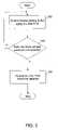
- FIG. 3is a flowchart of a method for preventing the failure of disk drives in storage system 100 , in accordance with one embodiment of the present invention.
- factors relating to the aging of each of disk drives 102are monitored.
- Factors that are related to aginginclude power-on hours (POH) and start stops (SS). POH is the sum total of the number of hours for which a particular disk drive has been powered on.
- MTTFmean-time-to-failure
- FIG. 4is a graph showing an exemplary variation of MTTF with temperature.
- the graph shownis applicable for disk drives manufactured by one specific disk vendor. Similar graphs are provided by other disk drive manufacturers. These graphs can be piecewise graphs as shown in FIG. 4 or linear graphs. This depends on the experimentation conducted by the disk drive manufacturer.
- MTTF versus temperature graphsare stored as vector pairs of MTTF values and temperatures. These vector pairs are stored as failure rate profiles 206 in memory 106 . For temperatures between the values stored in vector pairs, MTTF values are calculated by interpolation between consecutive vector pairs.
- the preset percentage for comparing the MTTF with the power-on hours of each of disk drives 102can be chosen between 0 and 0.2 (exclusive). Other percentages can be used. For example, one basis for choosing a percentage can be based on studies that have shown that useful life is smaller than that indicated by manufacturers' MTTF.
- MTTF(T)mean-time-to-failure calculated on the basis of temperature.
- Start stopsis the sum total of the number of times a disk drive completes a cycle of power on, disk drive usage and power off.
- SSis compared to a preset percentage of the maximum allowable value for the SS. This value is specified by drive manufacturers. Most drive manufacturers recommend the maximum allowable value for SS to be 50,000.
- the preset percentage for comparing the maximum allowable value of SS with the measured SS of each of disk drives 102can be chosen between 0 and 0.7 (exclusive). Therefore, an indication for replacement of a disk drive is given when: SS>c*SS max
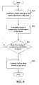
- FIG. 5is a flowchart of a method for preventing the failure of disk drives in storage system 100 , in accordance with another embodiment of the present invention.
- factors relating to the early onset of errors in each of disk drives 102are monitored.
- Factors that are related to the early onset of errorsinclude reallocated sector count (RSC), read error rate (RSE), seek error rate (SKE), spin retry count (SRC).
- RSCis defined as the number of spare sectors that have been reallocated. Data is stored in disk drives 102 in sectors. Disk drives 102 also include spare sectors to which data is not written. When a sector goes bad, i.e., data cannot be read or written from the sector, disk drives 102 reallocate spare sectors to store further data.
- RSCis compared to a preset percentage of the maximum allowable value for the RSC. This value is specified by the disk drive manufacturers. Most disk drive manufacturers recommend the maximum allowable value for RSC to be 1,500. The preset percentage for comparing the maximum allowable value of RSC with the measured RSC can be chosen between 0 and 0.7 (exclusive). Therefore, an indication for replacement is given when: RSC>r*RSC max
- RSC maxmaximum allowable value for RSC ⁇ 1,500
- Read error rateis the rate at which errors in reading data from disk drives occur. Read errors occur when a disk drive is unable to read data from a sector in the disk drive.
- RSEis compared to a preset percentage of the maximum allowable value for the RSE. This value is specified by disk drive manufacturers. Most disk drive manufacturers recommend the maximum allowable value for RSE to be one error in every 1024 sector read attempts.
- the preset percentage for comparing the maximum allowable value of RSE with the measured RSE of each of disk drives 102can be chosen between 0 and 0.7 (exclusive). Therefore, an indication for replacement is given when: RSE>m*RSE max
- RSE maxmaximum allowable value for RSE ⁇ 1 read error/1024 sector read attempts
- Seek error rateis the rate at which errors in seeking data from disk drives 102 occur. Seek errors occur when a disk drive is not able to locate where particular data is stored on the disk drive.
- SKEis compared to a preset percentage of the maximum allowable value for the SKE. This value is specified by disk drive manufacturers. Most disk drive manufacturers recommend the maximum allowable value for SKE to be one seek error in every 256 sector seek attempts.
- SKE maxmaximum allowable value for SKE ⁇ 1 seek error/256 sector seek attempts
- SRCSpin retry count
- SRCis defined as the number of attempts it takes to start the spinning of a disk drive.
- SRCis compared to a preset percentage of the maximum allowable value for the SRC. This value is specified by disk drive manufacturers. Most disk drive manufacturers recommend the maximum allowable value for SRC to be one spin failure in every 100 attempts.
- the preset percentage for comparing the maximum allowable value of SRC with the measured SRC of each of disk drives 102can be chosen between 0 and 0.3 (exclusive). Therefore, an indication for replacement is given when: SRC>t*SRC max
- SRC maxmaximum allowable value for SRC ⁇ 1 spin failure/100 attempts.
- FIG. 6is a flowchart of a method for preventing the failure of disk drives in storage system 100 , in accordance with another embodiment of the present invention.
- a factor relating to the onset of errors in each of disk drives 102is measured.
- changes in the value of the factorare calculated.
- reallocated sector count(RSC) is considered as a factor relating to the onset of errors. Therefore, an indication for drive replacement is given when: RSC ( i+ 2) ⁇ RSC ( i+ 1)> RSC ( i+ 1) ⁇ RSC ( i ) AND RSC ( i+ 3) ⁇ RSC ( i+ 2)> RSC ( i+ 2) ⁇ RSC ( i+ 1) for any i
- spin retry countSRC
- seek errorsSKE
- read soft errorRSE
- recalibrate retryRRT
- read channel errorssuch as a Viterbi detector mean-square error (MSE), etc.
- MSEmean-square error
- Thresholds for comparing the factorsare obtained from manufacturers of disk drives.
- memory 106stores thresholds specific to disk drive manufacturers. These thresholds and their corresponding threshold percentages are stored in memory 106 as preset attribute thresholds 208 . This is useful in case plurality of disk drives 102 comprises disk drives obtained from different disk drive manufacturers. In this embodiment, factors obtained from a particular disk drive are compared with thresholds recommended by the manufacturer of the particular disk drive as well as empirical evidence gathered during testing of the drives.
- Combinations of the factors discussed abovecan also be used for predicting the failure of disk drives. When combinations of factors are monitored, they are compared with the corresponding thresholds that are stored in memory 106 . Further, environmental data obtained from environmental sensors 110 can also be used, in combination with the described factors, to predict the failure of disk drives. For example, in case the temperature of a disk drive exceeds a threshold value, an indication for replacement of the disk drive can be given.
- the inventionas described above can also be used to prevent the failure of disk drives in power-managed RAID systems where not all disk drives need to be powered on simultaneously.
- the power-managed schemehas been described in the co-pending U.S. patent application ‘Method and Apparatus for Power Efficient High-Capacity Storage System’ referenced above. In this scheme, sequential writing onto disk drives is implemented, unlike simultaneous writing as performed in RAID 5 scheme. Sequential writing onto disk drives saves power because it requires powering up of one disk drive at a time.
- storage deviceany type of storage unit can be adaptable to work with the present invention.
- disk drivestape drives, random access memory (RAM), etc.
- RAMrandom access memory
- Different present and future storage technologiescan be used such as those created with magnetic, solid-state, optical, bioelectric, nano-engineered, or other techniques.
- Storage unitscan be located either internally inside a computer or outside a computer in a separate housing that is connected to the computer.
- Storage units, controllers and other components of systems discussed hereincan be included at a single location or separated at different locations. Such components can be interconnected by any suitable means such as with networks, communication links or other technology.
- specific functionalitymay be discussed as operating at, or residing in or with, specific places and times, in general the functionality can be provided at different locations and times.
- functionalitysuch as data protection steps can be provided at different tiers of a hierarchical controller. Any type of RAID or RAIV arrangement or configuration can be used.
- a “processor” or “process”includes any human, hardware and/or software system, mechanism, or component that processes data, signals, or other information.
- a processorcan include a system with a general-purpose central processing unit, multiple processing units, dedicated circuitry for achieving functionality, or other systems. Processing need not be limited to a geographic location, or have temporal limitations. For example, a processor can perform its functions in “real time,” “offline,” in a “batch mode,” etc. Moreover, certain portions of processing can be performed at different times and at different locations, by different (or the same) processing systems.
- any signal arrows in the drawings/figuresshould be considered only as exemplary, and not limiting, unless otherwise specifically noted.
- the term “or” as used hereinis generally intended to mean “and/or” unless otherwise indicated. Combinations of components or steps will also be considered as being noted, where terminology is foreseen as rendering the ability to separate or combine is unclear.
Landscapes
- Engineering & Computer Science (AREA)
- Quality & Reliability (AREA)
- Theoretical Computer Science (AREA)
- Physics & Mathematics (AREA)
- General Engineering & Computer Science (AREA)
- General Physics & Mathematics (AREA)
- Debugging And Monitoring (AREA)
Abstract
Description
POH>p*MTTF(T)
SS>c*SSmax
RSC>r*RSCmax
RSE>m*RSEmax
SKE>s*SKEmax
where, s=preset percentage for RSE, 0<s<0.7, and
SRC>t*SRCmax
RSC(i+2)−RSC(i+1)>RSC(i+1)−RSC(i) AND
RSC(i+3)−RSC(i+2)>RSC(i+2)−RSC(i+1) for anyi
Claims (22)
Priority Applications (5)
| Application Number | Priority Date | Filing Date | Title |
|---|---|---|---|
| US10/937,226US7373559B2 (en) | 2003-09-11 | 2004-09-08 | Method and system for proactive drive replacement for high availability storage systems |
| US11/043,449US20060053338A1 (en) | 2004-09-08 | 2005-01-25 | Method and system for disk drive exercise and maintenance of high-availability storage systems |
| PCT/US2005/031578WO2006029098A2 (en) | 2004-09-08 | 2005-09-01 | System and method for proactive drive replacement in high availability storage systems |
| US11/281,697US20060090098A1 (en) | 2003-09-11 | 2005-11-16 | Proactive data reliability in a power-managed storage system |
| US12/099,714US7908526B2 (en) | 2004-09-08 | 2008-04-08 | Method and system for proactive drive replacement for high availability storage systems |
Applications Claiming Priority (2)
| Application Number | Priority Date | Filing Date | Title |
|---|---|---|---|
| US50184903P | 2003-09-11 | 2003-09-11 | |
| US10/937,226US7373559B2 (en) | 2003-09-11 | 2004-09-08 | Method and system for proactive drive replacement for high availability storage systems |
Related Child Applications (2)
| Application Number | Title | Priority Date | Filing Date |
|---|---|---|---|
| US11/043,449Continuation-In-PartUS20060053338A1 (en) | 2003-09-11 | 2005-01-25 | Method and system for disk drive exercise and maintenance of high-availability storage systems |
| US12/099,714ContinuationUS7908526B2 (en) | 2004-09-08 | 2008-04-08 | Method and system for proactive drive replacement for high availability storage systems |
Publications (2)
| Publication Number | Publication Date |
|---|---|
| US20050060618A1 US20050060618A1 (en) | 2005-03-17 |
| US7373559B2true US7373559B2 (en) | 2008-05-13 |
Family
ID=35997548
Family Applications (3)
| Application Number | Title | Priority Date | Filing Date |
|---|---|---|---|
| US10/937,226Expired - LifetimeUS7373559B2 (en) | 2003-09-11 | 2004-09-08 | Method and system for proactive drive replacement for high availability storage systems |
| US11/043,449AbandonedUS20060053338A1 (en) | 2003-09-11 | 2005-01-25 | Method and system for disk drive exercise and maintenance of high-availability storage systems |
| US12/099,714Expired - Fee RelatedUS7908526B2 (en) | 2004-09-08 | 2008-04-08 | Method and system for proactive drive replacement for high availability storage systems |
Family Applications After (2)
| Application Number | Title | Priority Date | Filing Date |
|---|---|---|---|
| US11/043,449AbandonedUS20060053338A1 (en) | 2003-09-11 | 2005-01-25 | Method and system for disk drive exercise and maintenance of high-availability storage systems |
| US12/099,714Expired - Fee RelatedUS7908526B2 (en) | 2004-09-08 | 2008-04-08 | Method and system for proactive drive replacement for high availability storage systems |
Country Status (2)
| Country | Link |
|---|---|
| US (3) | US7373559B2 (en) |
| WO (1) | WO2006029098A2 (en) |
Cited By (34)
| Publication number | Priority date | Publication date | Assignee | Title |
|---|---|---|---|---|
| US20070094443A1 (en)* | 2005-10-24 | 2007-04-26 | Digi-Flicks International, Inc. | Digital storage memory module apparatus and method |
| US20080046998A1 (en)* | 2006-07-27 | 2008-02-21 | Lenova (Singapore) Ptc. Ltd. | Apparatus and method for assuring secure disposal of a hard disk drive unit |
| US20080077822A1 (en)* | 2006-09-22 | 2008-03-27 | Kabushiki Kaisha Toshiba | Information processing apparatus and disk drive control method |
| US20080109546A1 (en)* | 2004-05-12 | 2008-05-08 | Hitachi, Ltd. | Fault recovery method in a system having a plurality of storage system |
| US20080117751A1 (en)* | 2006-11-22 | 2008-05-22 | Read Christopher J | Jukebox disc deterioration testing |
| US20080244318A1 (en)* | 2004-09-08 | 2008-10-02 | Copan Systems | Method and system for proactive drive replacement for high availability storage systems |
| US20080244309A1 (en)* | 2007-03-29 | 2008-10-02 | Osanori Fukuyama | Disk array device, operating method thereof and program-storing medium |
| US20090228674A1 (en)* | 2008-03-05 | 2009-09-10 | Katsumi Ouchi | Disk array apparatus for controlling start timing of disk drive |
| US20090271657A1 (en)* | 2008-04-28 | 2009-10-29 | Mccombs Craig C | Drive health monitoring with provisions for drive probation state and drive copy rebuild |
| US20100100764A1 (en)* | 2008-10-17 | 2010-04-22 | International Business Machines Corporation | Redundancy information for adjusting threshold for component failure in a multi-layer system |
| US20100114838A1 (en)* | 2008-10-20 | 2010-05-06 | Honeywell International Inc. | Product reliability tracking and notification system and method |
| US20100138682A1 (en)* | 2008-11-28 | 2010-06-03 | Manabu Obana | Storage management server and storage configuration relocating method |
| US20100198635A1 (en)* | 2009-02-05 | 2010-08-05 | Honeywell International Inc., Patent Services | System and method for product deployment and in-service product risk simulation |
| US20100277822A1 (en)* | 2007-07-10 | 2010-11-04 | Monte Davidoff | Method and Apparatus to Facilitate Selection of a Digital Cinematic Content Write Process |
| US20100318553A1 (en)* | 2009-06-11 | 2010-12-16 | Honeywell International Inc. | Product fix-effectiveness tracking and notification system and method |
| US8225159B1 (en) | 2008-04-25 | 2012-07-17 | Netapp, Inc. | Method and system for implementing power savings features on storage devices within a storage subsystem |
| US20150074468A1 (en)* | 2013-09-11 | 2015-03-12 | Dell Produts, LP | SAN Vulnerability Assessment Tool |
| US9036283B1 (en) | 2014-01-22 | 2015-05-19 | Western Digital Technologies, Inc. | Data storage device with selective write to a first storage media or a second storage media |
| US9053747B1 (en) | 2013-01-29 | 2015-06-09 | Western Digitial Technologies, Inc. | Disk drive calibrating failure threshold based on noise power effect on failure detection metric |
| US20150205667A1 (en)* | 2014-01-23 | 2015-07-23 | DSSD, Inc. | Method and system for service-aware data placement in a storage system |
| CN104809032A (en)* | 2014-01-23 | 2015-07-29 | Dssd股份有限公司 | Method and system for service-aware parity placement in a storage system |
| US9263088B2 (en) | 2014-03-21 | 2016-02-16 | Western Digital Technologies, Inc. | Data management for a data storage device using a last resort zone |
| US9396200B2 (en) | 2013-09-11 | 2016-07-19 | Dell Products, Lp | Auto-snapshot manager analysis tool |
| US9454423B2 (en) | 2013-09-11 | 2016-09-27 | Dell Products, Lp | SAN performance analysis tool |
| US9535779B1 (en)* | 2014-07-25 | 2017-01-03 | Emc Corporation | Method and system for predicting redundant array of independent disks (RAID) vulnerability |
| US9632871B2 (en) | 2014-04-24 | 2017-04-25 | International Business Machines Corporation | Reuse of problematic disks in a redundant disk system |
| US9720758B2 (en) | 2013-09-11 | 2017-08-01 | Dell Products, Lp | Diagnostic analysis tool for disk storage engineering and technical support |
| US10198196B2 (en)* | 2014-03-31 | 2019-02-05 | EMC IP Holding Company LLC | Monitoring health condition of a hard disk |
| US10223230B2 (en) | 2013-09-11 | 2019-03-05 | Dell Products, Lp | Method and system for predicting storage device failures |
| US20200081439A1 (en)* | 2018-09-12 | 2020-03-12 | International Business Machines Corporation | Automated maintenance of datacenter computers using mobile robotic manipulators |
| US10831382B2 (en) | 2017-11-29 | 2020-11-10 | International Business Machines Corporation | Prevent disk hardware failure for cloud applications |
| US11209988B2 (en)* | 2019-05-21 | 2021-12-28 | International Business Machines Corporation | Dynamic storage volume distribution according to wearing level |
| US11513712B2 (en) | 2020-04-30 | 2022-11-29 | EMC IP Holding Company LLC | Method for storage management, device and computer program product |
| US11669250B2 (en) | 2020-10-22 | 2023-06-06 | EMC IP Holding Company LLC | Method, device, and computer program product for managing wear level of storage system |
Families Citing this family (58)
| Publication number | Priority date | Publication date | Assignee | Title |
|---|---|---|---|---|
| US7426534B2 (en)* | 2001-12-19 | 2008-09-16 | International Business Machines Corporation | Method and system for caching message fragments using an expansion attribute in a fragment link tag |
| US7210005B2 (en)* | 2002-09-03 | 2007-04-24 | Copan Systems, Inc. | Method and apparatus for power-efficient high-capacity scalable storage system |
| US7210004B2 (en)* | 2003-06-26 | 2007-04-24 | Copan Systems | Method and system for background processing of data in a storage system |
| US7434097B2 (en)* | 2003-06-05 | 2008-10-07 | Copan System, Inc. | Method and apparatus for efficient fault-tolerant disk drive replacement in raid storage systems |
| US20050210304A1 (en)* | 2003-06-26 | 2005-09-22 | Copan Systems | Method and apparatus for power-efficient high-capacity scalable storage system |
| US20060090098A1 (en)* | 2003-09-11 | 2006-04-27 | Copan Systems, Inc. | Proactive data reliability in a power-managed storage system |
| JP2005100259A (en) | 2003-09-26 | 2005-04-14 | Hitachi Ltd | Array type disk device, program and method for preventing double failure of drive |
| US7434090B2 (en)* | 2004-09-30 | 2008-10-07 | Copan System, Inc. | Method and apparatus for just in time RAID spare drive pool management |
| JP2006164445A (en)* | 2004-12-09 | 2006-06-22 | Fujitsu Ltd | Monitoring device |
| US20060200726A1 (en)* | 2005-03-03 | 2006-09-07 | Seagate Technology Llc | Failure trend detection and correction in a data storage array |
| JP4751153B2 (en)* | 2005-06-08 | 2011-08-17 | 株式会社日立製作所 | Storage system |
| US20070079170A1 (en)* | 2005-09-30 | 2007-04-05 | Zimmer Vincent J | Data migration in response to predicted disk failure |
| JP2007122108A (en)* | 2005-10-25 | 2007-05-17 | Hitachi Ltd | Control of storage system using disk drive device with self-check function |
| US8020047B2 (en)* | 2006-01-17 | 2011-09-13 | Xyratex Technology Limited | Method and apparatus for managing storage of data |
| US7721157B2 (en)* | 2006-03-08 | 2010-05-18 | Omneon Video Networks | Multi-node computer system component proactive monitoring and proactive repair |
| US20070244827A1 (en)* | 2006-04-18 | 2007-10-18 | Sony Corporation | Method for Securing a Hard Drive and Preventing Cloning or Tampering Attacks |
| JPWO2009040995A1 (en)* | 2007-09-25 | 2011-01-13 | パナソニック株式会社 | Information processing apparatus and information processing method |
| US20090161243A1 (en)* | 2007-12-21 | 2009-06-25 | Ratnesh Sharma | Monitoring Disk Drives To Predict Failure |
| KR20090078689A (en)* | 2008-01-15 | 2009-07-20 | 삼성전자주식회사 | How to Control Auto-Reallocation of Hard Disk Drives and Hard Disk Drives |
| US8041991B2 (en)* | 2008-11-18 | 2011-10-18 | Lsi Corporation | System and method for recovering solid state drive data |
| US8560106B2 (en)* | 2010-11-30 | 2013-10-15 | Applied Materials, Inc. | Predictive maintenance for third party support equipment |
| US8570678B2 (en) | 2011-11-18 | 2013-10-29 | Hewlett-Packard Development Company, L.P. | Determining tape head condition |
| US9087019B2 (en) | 2012-01-27 | 2015-07-21 | Promise Technology, Inc. | Disk storage system with rebuild sequence and method of operation thereof |
| US8839046B2 (en)* | 2012-07-10 | 2014-09-16 | International Business Machines Corporation | Arranging data handling in a computer-implemented system in accordance with reliability ratings based on reverse predictive failure analysis in response to changes |
| EP2901284A4 (en)* | 2012-09-28 | 2016-06-01 | Longsand Ltd | Predicting failure of a storage device |
| US8984333B2 (en) | 2013-01-11 | 2015-03-17 | International Business Machines Corporation | Automatic computer storage medium diagnostics |
| KR102100458B1 (en)* | 2013-04-19 | 2020-04-13 | 삼성전자주식회사 | Method for managing memory and an electronic device thereof |
| US9766980B1 (en)* | 2013-05-03 | 2017-09-19 | EMC IP Holding Company LLC | RAID failure prevention |
| CN104426696B (en)* | 2013-08-29 | 2018-09-07 | 深圳市腾讯计算机系统有限公司 | A kind of method of troubleshooting, server and system |
| JP6191346B2 (en)* | 2013-09-09 | 2017-09-06 | 富士通株式会社 | Storage control device, disk array device control method, and disk array device control program |
| US9436411B2 (en) | 2014-03-28 | 2016-09-06 | Dell Products, Lp | SAN IP validation tool |
| US20160041762A1 (en) | 2014-08-08 | 2016-02-11 | Kabushiki Kaisha Toshiba | Memory system, host device and information processing system |
| US9535619B2 (en)* | 2014-11-10 | 2017-01-03 | Dell Products, Lp | Enhanced reconstruction in an array of information storage devices by physical disk reduction without losing data |
| US9639436B2 (en)* | 2015-01-29 | 2017-05-02 | Dell Products, Lp | Synchronous replication error detection and handling |
| JP2016189227A (en)* | 2015-03-30 | 2016-11-04 | 株式会社日立エルジーデータストレージ | Data archiving system |
| JP6477320B2 (en)* | 2015-07-17 | 2019-03-06 | 富士通株式会社 | Storage device control device, storage device control method, and storage device control program |
| US10198061B2 (en)* | 2015-09-01 | 2019-02-05 | Toshiba Memory Corporation | Storage and storage system |
| US10599349B2 (en)* | 2015-09-11 | 2020-03-24 | Samsung Electronics Co., Ltd. | Method and apparatus of dynamic parallelism for controlling power consumption of SSDs |
| US9704538B2 (en) | 2015-10-30 | 2017-07-11 | Seagate Technology Llc | Environmentally controlling an enclosure |
| US10089178B2 (en)* | 2016-02-29 | 2018-10-02 | International Business Machines Corporation | Developing an accurate dispersed storage network memory performance model through training |
| US10254985B2 (en)* | 2016-03-15 | 2019-04-09 | Western Digital Technologies, Inc. | Power management of storage devices |
| US10013321B1 (en)* | 2016-06-22 | 2018-07-03 | EMC IP Holding Company LLC | Early raid rebuild to improve reliability |
| US10191668B1 (en)* | 2016-06-27 | 2019-01-29 | EMC IP Holding Company LLC | Method for dynamically modeling medium error evolution to predict disk failure |
| US10223224B1 (en)* | 2016-06-27 | 2019-03-05 | EMC IP Holding Company LLC | Method and system for automatic disk failure isolation, diagnosis, and remediation |
| US10747606B1 (en)* | 2016-12-21 | 2020-08-18 | EMC IP Holding Company LLC | Risk based analysis of adverse event impact on system availability |
| US10474551B2 (en)* | 2017-06-30 | 2019-11-12 | Wipro Limited | Method and system for recovering data from storage systems |
| US10783029B2 (en)* | 2017-07-17 | 2020-09-22 | Seagate Technology Llc | Data replication in a storage system |
| US10613962B1 (en)* | 2017-10-26 | 2020-04-07 | Amazon Technologies, Inc. | Server failure predictive model |
| CN108228377B (en)* | 2017-12-29 | 2020-07-07 | 华中科技大学 | SMART threshold value optimization method for disk fault detection |
| US10896114B2 (en) | 2018-05-23 | 2021-01-19 | Seagate Technology Llc | Machine learning error prediction in storage arrays |
| US10656990B2 (en) | 2018-06-13 | 2020-05-19 | Nutanix, Inc. | Dynamically adjusting reserve portion and allocation portions of disaster recovery site in a virtual computing system |
| EP3756051B1 (en) | 2018-09-11 | 2025-06-25 | Hewlett-Packard Development Company, L.P. | Hardware replacement predictions verified by local diagnostics |
| US11257001B2 (en) | 2018-10-09 | 2022-02-22 | International Business Machines Corporation | Prediction model enhancement |
| CN110147299B (en)* | 2019-05-15 | 2023-08-29 | 深圳忆联信息系统有限公司 | Method and system for detecting abnormal power failure of SSD (solid State disk) complete machine |
| US11442826B2 (en)* | 2019-06-15 | 2022-09-13 | International Business Machines Corporation | Reducing incidents of data loss in raid arrays having the same raid level |
| US11237890B2 (en) | 2019-08-21 | 2022-02-01 | International Business Machines Corporation | Analytics initiated predictive failure and smart log |
| US11314442B2 (en) | 2019-12-04 | 2022-04-26 | International Business Machines Corporation | Maintaining namespace health within a dispersed storage network |
| US12282382B2 (en) | 2022-09-28 | 2025-04-22 | International Business Machines Corporation | Quadrant matrix based priority calls for failed drives replacement |
Citations (43)
| Publication number | Priority date | Publication date | Assignee | Title |
|---|---|---|---|---|
| US4467421A (en) | 1979-10-18 | 1984-08-21 | Storage Technology Corporation | Virtual storage system and method |
| US5088081A (en) | 1990-03-28 | 1992-02-11 | Prime Computer, Inc. | Method and apparatus for improved disk access |
| US5371882A (en)* | 1992-01-14 | 1994-12-06 | Storage Technology Corporation | Spare disk drive replacement scheduling system for a disk drive array data storage subsystem |
| US5410439A (en)* | 1992-05-19 | 1995-04-25 | International Business Machines Corporation | Disk file with clearance and glide measurement and early head crash warning |
| US5438674A (en) | 1988-04-05 | 1995-08-01 | Data/Ware Development, Inc. | Optical disk system emulating magnetic tape units |
| US5530658A (en) | 1994-12-07 | 1996-06-25 | International Business Machines Corporation | System and method for packing heat producing devices in an array to prevent local overheating |
| US5539592A (en)* | 1994-10-05 | 1996-07-23 | International Business Machines Corporation | System and method for monitoring friction between head and disk to predict head disk interaction failure in direct access storage devices |
| US5557183A (en)* | 1993-07-29 | 1996-09-17 | International Business Machines Corporation | Method and apparatus for predicting failure of a disk drive |
| US5612845A (en)* | 1994-12-27 | 1997-03-18 | International Business Machines Corporation | Method and apparatus for in-situ detection of data storage system spindle motor performance degradation |
| US5666538A (en) | 1995-06-07 | 1997-09-09 | Ast Research, Inc. | Disk power manager for network servers |
| US5680579A (en) | 1994-11-10 | 1997-10-21 | Kaman Aerospace Corporation | Redundant array of solid state memory devices |
| US5720025A (en)* | 1996-01-18 | 1998-02-17 | Hewlett-Packard Company | Frequently-redundant array of independent disks |
| US5805864A (en) | 1996-09-10 | 1998-09-08 | International Business Machines Corporation | Virtual integrated cartridge loader for virtual tape storage system |
| US5828583A (en)* | 1992-08-21 | 1998-10-27 | Compaq Computer Corporation | Drive failure prediction techniques for disk drives |
| US5913927A (en)* | 1995-12-15 | 1999-06-22 | Mylex Corporation | Method and apparatus for management of faulty data in a raid system |
| US5917724A (en)* | 1997-12-20 | 1999-06-29 | Ncr Corporation | Method for predicting disk drive failure by monitoring the rate of growth of defects within a disk drive |
| US5923876A (en)* | 1995-08-24 | 1999-07-13 | Compaq Computer Corp. | Disk fault prediction system |
| US5935261A (en)* | 1997-06-05 | 1999-08-10 | International Business Machines Corporation | Method and apparatus for detecting handling damage in a disk drive |
| US6078455A (en)* | 1997-06-13 | 2000-06-20 | Seagate Technology, Inc. | Temperature dependent disc drive parametric configuration |
| US6128698A (en) | 1997-08-04 | 2000-10-03 | Exabyte Corporation | Tape drive emulator for removable disk drive |
| US20020007464A1 (en) | 1990-06-01 | 2002-01-17 | Amphus, Inc. | Apparatus and method for modular dynamically power managed power supply and cooling system for computer systems, server applications, and other electronic devices |
| US20020062454A1 (en) | 2000-09-27 | 2002-05-23 | Amphus, Inc. | Dynamic power and workload management for multi-server system |
| US20020144057A1 (en) | 2001-01-30 | 2002-10-03 | Data Domain | Archival data storage system and method |
| US6467054B1 (en)* | 1995-03-13 | 2002-10-15 | Compaq Computer Corporation | Self test for storage device |
| US20030112538A1 (en)* | 2001-12-18 | 2003-06-19 | International Business Machines Corporation; | Adaptive event-based predictive failure analysis measurements in a hard disk drive |
| US6600614B2 (en)* | 2000-09-28 | 2003-07-29 | Seagate Technology Llc | Critical event log for a disc drive |
| US20030196126A1 (en) | 2002-04-11 | 2003-10-16 | Fung Henry T. | System, method, and architecture for dynamic server power management and dynamic workload management for multi-server environment |
| US20030216888A1 (en)* | 2001-03-28 | 2003-11-20 | Ridolfo Charles F. | Predictive maintenance display system |
| US20040006702A1 (en) | 2001-08-01 | 2004-01-08 | Johnson R. Brent | System and method for virtual tape management with remote archival and retrieval via an encrypted validation communication protocol |
| US6680806B2 (en)* | 2000-01-19 | 2004-01-20 | Hitachi Global Storage Technologies Netherlands B.V. | System and method for gracefully relinquishing a computer hard disk drive from imminent catastrophic failure |
| US20040051988A1 (en)* | 2002-09-16 | 2004-03-18 | Jing Gary Gang | Predictive disc drive failure methodology |
| US20040111251A1 (en) | 2002-12-09 | 2004-06-10 | Alacritus, Inc. | Method and system for emulating tape libraries |
| US20040153614A1 (en) | 2003-02-05 | 2004-08-05 | Haim Bitner | Tape storage emulation for open systems environments |
| US6928556B2 (en)* | 2001-08-30 | 2005-08-09 | International Business Machines Corporation | Method and apparatus in a data processing system for managing situations from correlated events |
| US20050177755A1 (en) | 2000-09-27 | 2005-08-11 | Amphus, Inc. | Multi-server and multi-CPU power management system and method |
| US20050210304A1 (en) | 2003-06-26 | 2005-09-22 | Copan Systems | Method and apparatus for power-efficient high-capacity scalable storage system |
| US6957291B2 (en) | 2001-03-29 | 2005-10-18 | Quantum Corporation | Removable disk storage array emulating tape library having backup and archive capability |
| US6986075B2 (en)* | 2001-02-23 | 2006-01-10 | Hewlett-Packard Development Company, L.P. | Storage-device activation control for a high-availability storage system |
| US20060053338A1 (en) | 2004-09-08 | 2006-03-09 | Copan Systems, Inc. | Method and system for disk drive exercise and maintenance of high-availability storage systems |
| US7035972B2 (en) | 2002-09-03 | 2006-04-25 | Copan Systems, Inc. | Method and apparatus for power-efficient high-capacity scalable storage system |
| US7107491B2 (en)* | 2001-05-16 | 2006-09-12 | General Electric Company | System, method and computer product for performing automated predictive reliability |
| US20070079170A1 (en)* | 2005-09-30 | 2007-04-05 | Zimmer Vincent J | Data migration in response to predicted disk failure |
| US7210004B2 (en) | 2003-06-26 | 2007-04-24 | Copan Systems | Method and system for background processing of data in a storage system |
Family Cites Families (19)
| Publication number | Priority date | Publication date | Assignee | Title |
|---|---|---|---|---|
| JP2743606B2 (en)* | 1991-04-11 | 1998-04-22 | 三菱電機株式会社 | Array type recording device |
| JP2548480B2 (en)* | 1992-02-10 | 1996-10-30 | 富士通株式会社 | Disk device diagnostic method for array disk device |
| US5423046A (en) | 1992-12-17 | 1995-06-06 | International Business Machines Corporation | High capacity data storage system using disk array |
| US5560022A (en) | 1994-07-19 | 1996-09-24 | Intel Corporation | Power management coordinator system and interface |
| US5834856A (en)* | 1997-08-15 | 1998-11-10 | Compaq Computer Corporation | Computer system comprising a method and apparatus for periodic testing of redundant devices |
| JP3952561B2 (en)* | 1997-11-19 | 2007-08-01 | トヨタ自動車株式会社 | Exhaust gas purification device for internal combustion engine |
| US6249887B1 (en)* | 1998-09-21 | 2001-06-19 | William G. Gray | Apparatus and method for predicting failure of a disk drive |
| US6401214B1 (en)* | 1999-03-04 | 2002-06-04 | International Business Machines Corporation | Preventive recovery action in hard disk drives |
| JP4325817B2 (en)* | 1999-04-05 | 2009-09-02 | 株式会社日立製作所 | Disk array device |
| EP1299522B1 (en)* | 2000-06-30 | 2011-11-02 | University Of Louisville Research Foundation, Inc. | Alteration of cell membrane |
| US6834353B2 (en)* | 2001-10-22 | 2004-12-21 | International Business Machines Corporation | Method and apparatus for reducing power consumption of a processing integrated circuit |
| US7043650B2 (en) | 2001-10-31 | 2006-05-09 | Hewlett-Packard Development Company, L.P. | System and method for intelligent control of power consumption of distributed services during periods when power consumption must be reduced |
| WO2004025650A1 (en)* | 2002-09-16 | 2004-03-25 | Seagate Technology, Inc. | Predictive disc drive failure methodology |
| US6885974B2 (en)* | 2003-01-31 | 2005-04-26 | Microsoft Corporation | Dynamic power control apparatus, systems and methods |
| US7266668B2 (en)* | 2003-11-24 | 2007-09-04 | Copan Systems Inc. | Method and system for accessing a plurality of storage devices |
| US20050283682A1 (en)* | 2004-06-18 | 2005-12-22 | Hitachi, Ltd. | Method for data protection in disk array systems |
| JP4884885B2 (en)* | 2006-08-25 | 2012-02-29 | 株式会社日立製作所 | Storage controller and storage controller failure recovery method |
| JP5057741B2 (en)* | 2006-10-12 | 2012-10-24 | 株式会社日立製作所 | Storage device |
| US7930596B2 (en)* | 2008-05-29 | 2011-04-19 | International Business Machines Corporation | Managing execution stability of an application carried out using a plurality of pluggable processing components |
- 2004
- 2004-09-08USUS10/937,226patent/US7373559B2/ennot_activeExpired - Lifetime
- 2005
- 2005-01-25USUS11/043,449patent/US20060053338A1/ennot_activeAbandoned
- 2005-09-01WOPCT/US2005/031578patent/WO2006029098A2/enactiveApplication Filing
- 2008
- 2008-04-08USUS12/099,714patent/US7908526B2/ennot_activeExpired - Fee Related
Patent Citations (48)
| Publication number | Priority date | Publication date | Assignee | Title |
|---|---|---|---|---|
| US4467421A (en) | 1979-10-18 | 1984-08-21 | Storage Technology Corporation | Virtual storage system and method |
| US5438674A (en) | 1988-04-05 | 1995-08-01 | Data/Ware Development, Inc. | Optical disk system emulating magnetic tape units |
| US5088081A (en) | 1990-03-28 | 1992-02-11 | Prime Computer, Inc. | Method and apparatus for improved disk access |
| US6859882B2 (en)* | 1990-06-01 | 2005-02-22 | Amphus, Inc. | System, method, and architecture for dynamic server power management and dynamic workload management for multi-server environment |
| US20030200473A1 (en) | 1990-06-01 | 2003-10-23 | Amphus, Inc. | System and method for activity or event based dynamic energy conserving server reconfiguration |
| US20020007464A1 (en) | 1990-06-01 | 2002-01-17 | Amphus, Inc. | Apparatus and method for modular dynamically power managed power supply and cooling system for computer systems, server applications, and other electronic devices |
| US5371882A (en)* | 1992-01-14 | 1994-12-06 | Storage Technology Corporation | Spare disk drive replacement scheduling system for a disk drive array data storage subsystem |
| US5410439A (en)* | 1992-05-19 | 1995-04-25 | International Business Machines Corporation | Disk file with clearance and glide measurement and early head crash warning |
| US5828583A (en)* | 1992-08-21 | 1998-10-27 | Compaq Computer Corporation | Drive failure prediction techniques for disk drives |
| US5557183A (en)* | 1993-07-29 | 1996-09-17 | International Business Machines Corporation | Method and apparatus for predicting failure of a disk drive |
| US5539592A (en)* | 1994-10-05 | 1996-07-23 | International Business Machines Corporation | System and method for monitoring friction between head and disk to predict head disk interaction failure in direct access storage devices |
| US5680579A (en) | 1994-11-10 | 1997-10-21 | Kaman Aerospace Corporation | Redundant array of solid state memory devices |
| US5787462A (en) | 1994-12-07 | 1998-07-28 | International Business Machines Corporation | System and method for memory management in an array of heat producing devices to prevent local overheating |
| US5530658A (en) | 1994-12-07 | 1996-06-25 | International Business Machines Corporation | System and method for packing heat producing devices in an array to prevent local overheating |
| US5612845A (en)* | 1994-12-27 | 1997-03-18 | International Business Machines Corporation | Method and apparatus for in-situ detection of data storage system spindle motor performance degradation |
| US6467054B1 (en)* | 1995-03-13 | 2002-10-15 | Compaq Computer Corporation | Self test for storage device |
| US5961613A (en) | 1995-06-07 | 1999-10-05 | Ast Research, Inc. | Disk power manager for network servers |
| US5666538A (en) | 1995-06-07 | 1997-09-09 | Ast Research, Inc. | Disk power manager for network servers |
| US5923876A (en)* | 1995-08-24 | 1999-07-13 | Compaq Computer Corp. | Disk fault prediction system |
| US5913927A (en)* | 1995-12-15 | 1999-06-22 | Mylex Corporation | Method and apparatus for management of faulty data in a raid system |
| US5720025A (en)* | 1996-01-18 | 1998-02-17 | Hewlett-Packard Company | Frequently-redundant array of independent disks |
| US5805864A (en) | 1996-09-10 | 1998-09-08 | International Business Machines Corporation | Virtual integrated cartridge loader for virtual tape storage system |
| US5935261A (en)* | 1997-06-05 | 1999-08-10 | International Business Machines Corporation | Method and apparatus for detecting handling damage in a disk drive |
| US6078455A (en)* | 1997-06-13 | 2000-06-20 | Seagate Technology, Inc. | Temperature dependent disc drive parametric configuration |
| US6128698A (en) | 1997-08-04 | 2000-10-03 | Exabyte Corporation | Tape drive emulator for removable disk drive |
| US5917724A (en)* | 1997-12-20 | 1999-06-29 | Ncr Corporation | Method for predicting disk drive failure by monitoring the rate of growth of defects within a disk drive |
| US6680806B2 (en)* | 2000-01-19 | 2004-01-20 | Hitachi Global Storage Technologies Netherlands B.V. | System and method for gracefully relinquishing a computer hard disk drive from imminent catastrophic failure |
| US20020062454A1 (en) | 2000-09-27 | 2002-05-23 | Amphus, Inc. | Dynamic power and workload management for multi-server system |
| US20050177755A1 (en) | 2000-09-27 | 2005-08-11 | Amphus, Inc. | Multi-server and multi-CPU power management system and method |
| US6600614B2 (en)* | 2000-09-28 | 2003-07-29 | Seagate Technology Llc | Critical event log for a disc drive |
| US20020144057A1 (en) | 2001-01-30 | 2002-10-03 | Data Domain | Archival data storage system and method |
| US6986075B2 (en)* | 2001-02-23 | 2006-01-10 | Hewlett-Packard Development Company, L.P. | Storage-device activation control for a high-availability storage system |
| US20030216888A1 (en)* | 2001-03-28 | 2003-11-20 | Ridolfo Charles F. | Predictive maintenance display system |
| US6957291B2 (en) | 2001-03-29 | 2005-10-18 | Quantum Corporation | Removable disk storage array emulating tape library having backup and archive capability |
| US7107491B2 (en)* | 2001-05-16 | 2006-09-12 | General Electric Company | System, method and computer product for performing automated predictive reliability |
| US20040006702A1 (en) | 2001-08-01 | 2004-01-08 | Johnson R. Brent | System and method for virtual tape management with remote archival and retrieval via an encrypted validation communication protocol |
| US6928556B2 (en)* | 2001-08-30 | 2005-08-09 | International Business Machines Corporation | Method and apparatus in a data processing system for managing situations from correlated events |
| US20030112538A1 (en)* | 2001-12-18 | 2003-06-19 | International Business Machines Corporation; | Adaptive event-based predictive failure analysis measurements in a hard disk drive |
| US20030196126A1 (en) | 2002-04-11 | 2003-10-16 | Fung Henry T. | System, method, and architecture for dynamic server power management and dynamic workload management for multi-server environment |
| US7035972B2 (en) | 2002-09-03 | 2006-04-25 | Copan Systems, Inc. | Method and apparatus for power-efficient high-capacity scalable storage system |
| US6982842B2 (en)* | 2002-09-16 | 2006-01-03 | Seagate Technology Llc | Predictive disc drive failure methodology |
| US20040051988A1 (en)* | 2002-09-16 | 2004-03-18 | Jing Gary Gang | Predictive disc drive failure methodology |
| US20040111251A1 (en) | 2002-12-09 | 2004-06-10 | Alacritus, Inc. | Method and system for emulating tape libraries |
| US20040153614A1 (en) | 2003-02-05 | 2004-08-05 | Haim Bitner | Tape storage emulation for open systems environments |
| US20050210304A1 (en) | 2003-06-26 | 2005-09-22 | Copan Systems | Method and apparatus for power-efficient high-capacity scalable storage system |
| US7210004B2 (en) | 2003-06-26 | 2007-04-24 | Copan Systems | Method and system for background processing of data in a storage system |
| US20060053338A1 (en) | 2004-09-08 | 2006-03-09 | Copan Systems, Inc. | Method and system for disk drive exercise and maintenance of high-availability storage systems |
| US20070079170A1 (en)* | 2005-09-30 | 2007-04-05 | Zimmer Vincent J | Data migration in response to predicted disk failure |
Non-Patent Citations (9)
| Title |
|---|
| Adam Weikal, Bruce Peterson, David L. Smith; Maxtor SMART/ DST User's Guide; Revision C; May 1, 2002; (C) Maxtor Corporation 2001; pp. 1-52. |
| Asaca/Shibasoku Corp of America, publication DM200, 1 page from www.asaca.com/DVL/DM<SUB>-</SUB>200.htm, Oct. 7, 2003. |
| Chase et al., "Managing Energy and Server Resources in Hosting Centers," Dept of Computer Science, Duke University, pp. 14, Oct. 2001. |
| Colarelli et al., The Cas for Massive Arrays of Idle Disks (MAID), Dept of Computer Science, Univ. of Colorado, Boulder, pp. 1-6, Jan. 7, 2002. |
| IDEMA Standard Document No. R2-98 pp. 1-21.* |
| Jim Herbst; SMART Specification For Seagate Technology Desktop and Mobile Drives; Version 2.28; Apr. 23, 2003; pp. 1-36. |
| Patterson et al., "A Case for Redundant Arrays of Inexpensive Disks (RAID)," ACM, pp. 109-116, 1998. |
| Reliability of Hard Disk Drives (HDD); (C) 2003 by CALCE and the University of Maryland; p. 1-2. |
| S.M.A.R.T. Design, Desktop HDD Development IDE, HDD Development, Storage M& D; Jul. 12, 2002; (C) 2001 IMB Corp.: pp. 1-19. |
Cited By (49)
| Publication number | Priority date | Publication date | Assignee | Title |
|---|---|---|---|---|
| US20080109546A1 (en)* | 2004-05-12 | 2008-05-08 | Hitachi, Ltd. | Fault recovery method in a system having a plurality of storage system |
| US7603583B2 (en)* | 2004-05-12 | 2009-10-13 | Hitachi, Ltd. | Fault recovery method in a system having a plurality of storage system |
| US20080244318A1 (en)* | 2004-09-08 | 2008-10-02 | Copan Systems | Method and system for proactive drive replacement for high availability storage systems |
| US7908526B2 (en)* | 2004-09-08 | 2011-03-15 | Silicon Graphics International | Method and system for proactive drive replacement for high availability storage systems |
| US7454562B2 (en)* | 2005-10-24 | 2008-11-18 | Digi-Flicks International, Inc. | Performance information in digital storage memory module apparatus and method |
| US20070094443A1 (en)* | 2005-10-24 | 2007-04-26 | Digi-Flicks International, Inc. | Digital storage memory module apparatus and method |
| US8381304B2 (en)* | 2006-07-27 | 2013-02-19 | Lenovo (Singapore) Pte. Ltd. | Apparatus and method for assuring secure disposal of a hard disk drive unit |
| US20080046998A1 (en)* | 2006-07-27 | 2008-02-21 | Lenova (Singapore) Ptc. Ltd. | Apparatus and method for assuring secure disposal of a hard disk drive unit |
| US20080077822A1 (en)* | 2006-09-22 | 2008-03-27 | Kabushiki Kaisha Toshiba | Information processing apparatus and disk drive control method |
| US20080117751A1 (en)* | 2006-11-22 | 2008-05-22 | Read Christopher J | Jukebox disc deterioration testing |
| US20080244309A1 (en)* | 2007-03-29 | 2008-10-02 | Osanori Fukuyama | Disk array device, operating method thereof and program-storing medium |
| US7890791B2 (en)* | 2007-03-29 | 2011-02-15 | Nec Corporation | Disk array device, operating method thereof and program-storing medium |
| US20100277822A1 (en)* | 2007-07-10 | 2010-11-04 | Monte Davidoff | Method and Apparatus to Facilitate Selection of a Digital Cinematic Content Write Process |
| US20090228674A1 (en)* | 2008-03-05 | 2009-09-10 | Katsumi Ouchi | Disk array apparatus for controlling start timing of disk drive |
| US8225159B1 (en) | 2008-04-25 | 2012-07-17 | Netapp, Inc. | Method and system for implementing power savings features on storage devices within a storage subsystem |
| US20090271657A1 (en)* | 2008-04-28 | 2009-10-29 | Mccombs Craig C | Drive health monitoring with provisions for drive probation state and drive copy rebuild |
| US8185784B2 (en)* | 2008-04-28 | 2012-05-22 | Lsi Corporation | Drive health monitoring with provisions for drive probation state and drive copy rebuild |
| US20100100764A1 (en)* | 2008-10-17 | 2010-04-22 | International Business Machines Corporation | Redundancy information for adjusting threshold for component failure in a multi-layer system |
| US8041984B2 (en)* | 2008-10-17 | 2011-10-18 | International Business Machines Corporation | Redundancy information for adjusting threshold for component failure in a multi-layer system |
| US20100114838A1 (en)* | 2008-10-20 | 2010-05-06 | Honeywell International Inc. | Product reliability tracking and notification system and method |
| US20100138682A1 (en)* | 2008-11-28 | 2010-06-03 | Manabu Obana | Storage management server and storage configuration relocating method |
| US8086888B2 (en)* | 2008-11-28 | 2011-12-27 | Hitachi, Ltd. | Storage management server and storage configuration relocating method |
| US8290802B2 (en) | 2009-02-05 | 2012-10-16 | Honeywell International Inc. | System and method for product deployment and in-service product risk simulation |
| US20100198635A1 (en)* | 2009-02-05 | 2010-08-05 | Honeywell International Inc., Patent Services | System and method for product deployment and in-service product risk simulation |
| US20100318553A1 (en)* | 2009-06-11 | 2010-12-16 | Honeywell International Inc. | Product fix-effectiveness tracking and notification system and method |
| US8266171B2 (en) | 2009-06-11 | 2012-09-11 | Honeywell International Inc. | Product fix-effectiveness tracking and notification system and method |
| US9053747B1 (en) | 2013-01-29 | 2015-06-09 | Western Digitial Technologies, Inc. | Disk drive calibrating failure threshold based on noise power effect on failure detection metric |
| US10223230B2 (en) | 2013-09-11 | 2019-03-05 | Dell Products, Lp | Method and system for predicting storage device failures |
| US9720758B2 (en) | 2013-09-11 | 2017-08-01 | Dell Products, Lp | Diagnostic analysis tool for disk storage engineering and technical support |
| US10459815B2 (en) | 2013-09-11 | 2019-10-29 | Dell Products, Lp | Method and system for predicting storage device failures |
| US20150074468A1 (en)* | 2013-09-11 | 2015-03-12 | Dell Produts, LP | SAN Vulnerability Assessment Tool |
| US9454423B2 (en) | 2013-09-11 | 2016-09-27 | Dell Products, Lp | SAN performance analysis tool |
| US9396200B2 (en) | 2013-09-11 | 2016-07-19 | Dell Products, Lp | Auto-snapshot manager analysis tool |
| US9317349B2 (en)* | 2013-09-11 | 2016-04-19 | Dell Products, Lp | SAN vulnerability assessment tool |
| US9298380B1 (en) | 2014-01-22 | 2016-03-29 | Western Digital Technologies, Inc. | Data storage device with selective write to a first storage media or a second storage media |
| US9036283B1 (en) | 2014-01-22 | 2015-05-19 | Western Digital Technologies, Inc. | Data storage device with selective write to a first storage media or a second storage media |
| CN104809032A (en)* | 2014-01-23 | 2015-07-29 | Dssd股份有限公司 | Method and system for service-aware parity placement in a storage system |
| US20150205667A1 (en)* | 2014-01-23 | 2015-07-23 | DSSD, Inc. | Method and system for service-aware data placement in a storage system |
| CN104809032B (en)* | 2014-01-23 | 2018-05-04 | Dssd股份有限公司 | The method and system that even-odd check for service-aware in storage system is placed |
| US9263088B2 (en) | 2014-03-21 | 2016-02-16 | Western Digital Technologies, Inc. | Data management for a data storage device using a last resort zone |
| US10198196B2 (en)* | 2014-03-31 | 2019-02-05 | EMC IP Holding Company LLC | Monitoring health condition of a hard disk |
| US9632871B2 (en) | 2014-04-24 | 2017-04-25 | International Business Machines Corporation | Reuse of problematic disks in a redundant disk system |
| US9535779B1 (en)* | 2014-07-25 | 2017-01-03 | Emc Corporation | Method and system for predicting redundant array of independent disks (RAID) vulnerability |
| US10831382B2 (en) | 2017-11-29 | 2020-11-10 | International Business Machines Corporation | Prevent disk hardware failure for cloud applications |
| US20200081439A1 (en)* | 2018-09-12 | 2020-03-12 | International Business Machines Corporation | Automated maintenance of datacenter computers using mobile robotic manipulators |
| US10935980B2 (en)* | 2018-09-12 | 2021-03-02 | International Business Machines Corporation | Automated maintenance of datacenter computers using mobile robotic manipulators |
| US11209988B2 (en)* | 2019-05-21 | 2021-12-28 | International Business Machines Corporation | Dynamic storage volume distribution according to wearing level |
| US11513712B2 (en) | 2020-04-30 | 2022-11-29 | EMC IP Holding Company LLC | Method for storage management, device and computer program product |
| US11669250B2 (en) | 2020-10-22 | 2023-06-06 | EMC IP Holding Company LLC | Method, device, and computer program product for managing wear level of storage system |
Also Published As
| Publication number | Publication date |
|---|---|
| US20060053338A1 (en) | 2006-03-09 |
| WO2006029098A2 (en) | 2006-03-16 |
| US20080244318A1 (en) | 2008-10-02 |
| US7908526B2 (en) | 2011-03-15 |
| US20050060618A1 (en) | 2005-03-17 |
| WO2006029098A3 (en) | 2007-05-10 |
Similar Documents
| Publication | Publication Date | Title |
|---|---|---|
| US7373559B2 (en) | Method and system for proactive drive replacement for high availability storage systems | |
| US20060090098A1 (en) | Proactive data reliability in a power-managed storage system | |
| US7526684B2 (en) | Deterministic preventive recovery from a predicted failure in a distributed storage system | |
| US6886108B2 (en) | Threshold adjustment following forced failure of storage device | |
| US6986075B2 (en) | Storage-device activation control for a high-availability storage system | |
| US7543178B2 (en) | Low cost RAID with seamless disk failure recovery | |
| US5500940A (en) | Method for evaluating failure in an electronic data storage system and preemptive notification thereof, and system with component failure evaluation | |
| US7434097B2 (en) | Method and apparatus for efficient fault-tolerant disk drive replacement in raid storage systems | |
| US9189309B1 (en) | System and method for predicting single-disk failures | |
| US8473779B2 (en) | Systems and methods for error correction and detection, isolation, and recovery of faults in a fail-in-place storage array | |
| US9229796B1 (en) | System and method for determining disk failure indicator to predict future disk failures | |
| US9141457B1 (en) | System and method for predicting multiple-disk failures | |
| US10013321B1 (en) | Early raid rebuild to improve reliability | |
| US7890791B2 (en) | Disk array device, operating method thereof and program-storing medium | |
| Elerath et al. | Server class disk drives: How reliable are they? | |
| US9766980B1 (en) | RAID failure prevention | |
| JP2007310974A (en) | Storage device and control device | |
| US7631067B2 (en) | Server initiated predictive failure analysis for disk drives | |
| US20090089503A1 (en) | Disk array apparatus, computer-readable recording medium having disk array apparatus control program recorded thereon, and disk array apparatus control method | |
| JP2005221413A (en) | Electronic device, failure prediction method, failure prediction program, and recording medium therefor | |
| US8234235B2 (en) | Security and remote support apparatus, system and method | |
| CN113179665A (en) | Identifying underperforming data storage devices using error correction based metrics | |
| JP6079578B2 (en) | Storage control device, storage control program, and storage control method | |
| US7457990B2 (en) | Information processing apparatus and information processing recovery method | |
| US10599343B2 (en) | Proactively resilvering a striped disk array in advance of a predicted disk drive failure |
Legal Events
| Date | Code | Title | Description |
|---|---|---|---|
| AS | Assignment | Owner name:COPAN SYSTEMS, INC., COLORADO Free format text:ASSIGNMENT OF ASSIGNORS INTEREST;ASSIGNOR:GUHA, ALOKE;REEL/FRAME:015782/0416 Effective date:20040908 | |
| STCF | Information on status: patent grant | Free format text:PATENTED CASE | |
| AS | Assignment | Owner name:SILICON VALLEY BANK, CALIFORNIA Free format text:SECURITY AGREEMENT;ASSIGNORS:COPAN SYSTEMS, INC.;COPAN SYSTEMS EMEA (PTY) LIMITED;REEL/FRAME:022228/0408 Effective date:20081024 Owner name:SILICON VALLEY BANK, CALIFORNIA Free format text:SECURITY AGREEMENT;ASSIGNOR:COPAN SYSTEMS, INC.;REEL/FRAME:022228/0601 Effective date:20081024 | |
| AS | Assignment | Owner name:WESTBURY INVESTMENT PARTNERS SBIC, LP, NEW YORK Free format text:SECURITY AGREEMENT;ASSIGNOR:COPAN SYSTEMS, INC.;REEL/FRAME:022309/0579 Effective date:20090209 | |
| AS | Assignment | Owner name:SILICON GRAPHICS INTERNATIONAL CORP.,CALIFORNIA Free format text:ASSIGNMENT OF ASSIGNORS INTEREST;ASSIGNOR:SILICON VALLEY BANK;REEL/FRAME:024351/0936 Effective date:20100223 Owner name:SILICON GRAPHICS INTERNATIONAL CORP., CALIFORNIA Free format text:ASSIGNMENT OF ASSIGNORS INTEREST;ASSIGNOR:SILICON VALLEY BANK;REEL/FRAME:024351/0936 Effective date:20100223 | |
| FPAY | Fee payment | Year of fee payment:4 | |
| AS | Assignment | Owner name:SILICON VALLEY BANK, CALIFORNIA Free format text:RELEASE BY SECURED PARTY;ASSIGNOR:WESTBURY INVESTMENT PARTNERS SBIC, LP;REEL/FRAME:032276/0091 Effective date:20100223 | |
| FEPP | Fee payment procedure | Free format text:PAT HOLDER NO LONGER CLAIMS SMALL ENTITY STATUS, ENTITY STATUS SET TO UNDISCOUNTED (ORIGINAL EVENT CODE: STOL); ENTITY STATUS OF PATENT OWNER: LARGE ENTITY | |
| AS | Assignment | Owner name:RPX CORPORATION, CALIFORNIA Free format text:ASSIGNMENT OF ASSIGNORS INTEREST;ASSIGNOR:SILICON GRAPHICS INTERNATIONAL CORP.;REEL/FRAME:035409/0615 Effective date:20150327 | |
| FPAY | Fee payment | Year of fee payment:8 | |
| AS | Assignment | Owner name:JPMORGAN CHASE BANK, N.A., AS COLLATERAL AGENT, IL Free format text:SECURITY AGREEMENT;ASSIGNORS:RPX CORPORATION;RPX CLEARINGHOUSE LLC;REEL/FRAME:038041/0001 Effective date:20160226 | |
| AS | Assignment | Owner name:RPX CORPORATION, CALIFORNIA Free format text:RELEASE (REEL 038041 / FRAME 0001);ASSIGNOR:JPMORGAN CHASE BANK, N.A.;REEL/FRAME:044970/0030 Effective date:20171222 Owner name:RPX CLEARINGHOUSE LLC, CALIFORNIA Free format text:RELEASE (REEL 038041 / FRAME 0001);ASSIGNOR:JPMORGAN CHASE BANK, N.A.;REEL/FRAME:044970/0030 Effective date:20171222 | |
| FEPP | Fee payment procedure | Free format text:MAINTENANCE FEE REMINDER MAILED (ORIGINAL EVENT CODE: REM.); ENTITY STATUS OF PATENT OWNER: LARGE ENTITY | |
| FEPP | Fee payment procedure | Free format text:11.5 YR SURCHARGE- LATE PMT W/IN 6 MO, LARGE ENTITY (ORIGINAL EVENT CODE: M1556); ENTITY STATUS OF PATENT OWNER: LARGE ENTITY | |
| MAFP | Maintenance fee payment | Free format text:PAYMENT OF MAINTENANCE FEE, 12TH YEAR, LARGE ENTITY (ORIGINAL EVENT CODE: M1553); ENTITY STATUS OF PATENT OWNER: LARGE ENTITY Year of fee payment:12 | |
| AS | Assignment | Owner name:BARINGS FINANCE LLC, AS COLLATERAL AGENT, NORTH CAROLINA Free format text:PATENT SECURITY AGREEMENT;ASSIGNORS:RPX CLEARINGHOUSE LLC;RPX CORPORATION;REEL/FRAME:054198/0029 Effective date:20201023 Owner name:BARINGS FINANCE LLC, AS COLLATERAL AGENT, NORTH CAROLINA Free format text:PATENT SECURITY AGREEMENT;ASSIGNORS:RPX CLEARINGHOUSE LLC;RPX CORPORATION;REEL/FRAME:054244/0566 Effective date:20200823 | |
| AS | Assignment | Owner name:RPX CORPORATION, CALIFORNIA Free format text:RELEASE OF LIEN ON PATENTS;ASSIGNOR:BARINGS FINANCE LLC;REEL/FRAME:068328/0278 Effective date:20240802 | |
| AS | Assignment | Owner name:BARINGS FINANCE LLC, AS COLLATERAL AGENT, NORTH CAROLINA Free format text:PATENT SECURITY AGREEMENT;ASSIGNORS:RPX CORPORATION;RPX CLEARINGHOUSE LLC;REEL/FRAME:068328/0674 Effective date:20240802 |