US7373528B2 - Increased power for power over Ethernet applications - Google Patents
Increased power for power over Ethernet applicationsDownload PDFInfo
- Publication number
- US7373528B2 US7373528B2US10/998,077US99807704AUS7373528B2US 7373528 B2US7373528 B2US 7373528B2US 99807704 AUS99807704 AUS 99807704AUS 7373528 B2US7373528 B2US 7373528B2
- Authority
- US
- United States
- Prior art keywords
- power
- over ethernet
- power over
- port
- powered device
- Prior art date
- Legal status (The legal status is an assumption and is not a legal conclusion. Google has not performed a legal analysis and makes no representation as to the accuracy of the status listed.)
- Active, expires
Links
Images


Classifications
- G—PHYSICS
- G06—COMPUTING OR CALCULATING; COUNTING
- G06F—ELECTRIC DIGITAL DATA PROCESSING
- G06F1/00—Details not covered by groups G06F3/00 - G06F13/00 and G06F21/00
- G06F1/26—Power supply means, e.g. regulation thereof
- G06F1/266—Arrangements to supply power to external peripherals either directly from the computer or under computer control, e.g. supply of power through the communication port, computer controlled power-strips
Definitions
- This inventionrelates generally to power over Ethernet applications and more particularly to a method and system for providing increased power for power over Ethernet applications.
- IEEEhas issued a standard, IEEE 802.3af, that specifies methods of power delivery over Ethernet.
- the standarddescribes the use of two of the four pairs to deliver power to a powered device.
- telecommunication devicesadapt to meet new communication demands, such devices may have different power needs, which may include the need for additional power.
- a method for supplying power over Ethernet cablesincludes determining whether a first port of power sourcing equipment is supplying current to a power over Ethernet powered device in a predetermined current range. The method also includes electrically connecting a second port of the power sourcing equipment to the power over Ethernet device in response to determining that a first port of the power sourcing equipment is supplying current to the power over Ethernet powered device. The method also includes supplying power from the second port to the power over Ethernet powered device.
- an apparatusincludes a current detection circuit operable to determine whether a first port of power sourcing equipment is supplying current to a power over Ethernet device and a switching circuit operable to receive an indication from the current detection circuit that the first port of the power sourcing equipment is supplying current to a power over Ethernet device and, in response, electrically connect a second port of the power sourcing equipment to the power over Ethernet device.
- the apparatusalso includes a detection circuit operable to mimic a valid power over Ethernet device.
- Important technical advantages of certain embodiments of the present inventioninclude the provision of increased power to a single powered device through a plurality of ports from power sourcing equipment. This allows, in some embodiments, for the powering of a high powered power over Ethernet device by standard power sourcing equipment that was not intended to necessarily provide such high levels of power to the powered device. This avoids retrofitting certain systems with specifically-designed power sourcing equipment for such high powered devices.
- Other technical advantages of the present inventionwill be readily apparent to ones skilled in the art form the following figures, descriptions, and claims.
- specific advantageshave been enumerated above, various embodiments may include all, some, or none of the enumerated advantages.
- FIG. 1is a block diagram of a power over Ethernet system according to the teachings of the invention.
- FIG. 2Ais a circuit diagram of portions of the power supply of FIG. 1 ;
- FIG. 2Bis a circuit diagram of portions of the adapter of FIG. 1 ;
- FIG. 2Cis a circuit diagram of portions of the high power powered device of FIG. 1 ;
- FIG. 2Dis a circuit diagram showing portions of the power supply, adapter circuitry, and high power powered device of FIG. 1 , all on the same figure;
- FIG. 3is a pin diagram illustrating connections of the adapter of FIGS. 1 and 2B ;
- FIG. 4is a block diagram illustrating a system for providing power to Ethernet devices according to yet another embodiment of the invention.
- FIG. 5is a schematic diagram illustrating one mechanical embodiment for the adapter of FIGS. 1 and 2B according to the teachings of the invention.
- FIG. 1illustrates a power delivery system 10 involving the delivery of power to one or more powered devices over Ethernet cables.
- System 10includes power sourcing equipment 11 for providing power, an adapter circuit 12 for taking power from more than one port of power sourcing equipment 11 and providing it to a single high power powered device 14 , the high power powered device 14 , and standard power powered devices 16 .
- High power powered device 14receives power from multiple ports of power sourcing equipment 11 , and often, requires more power than is capable of being supplied by a given port of power sourcing equipment 11 and that may consume power levels outside of current IEEE levels.
- adapter circuitry 12receives power from more than one port of power sourcing equipment 11 and provides this power to a single powered device, allowing a high power powered device to be powered by conventional power supplies having ports with maximum power outputs that individually cannot meet the power requirements of the high power powered device.
- one method for delivering increased power to power over Ethernet powered devicesis to provide power over all data pairs within an Ethernet cable. Traditionally, only half of the pairs are used to transmit power with the other half being used sometimes for data and sometimes not being used at all.
- an adapteris provided that takes power from multiple ports of a power supply to produce increased power for that powered device.
- Power sourcing equipment 11includes multiple ports 18 , 20 , and 22 .
- a controller 40controls power source 42 and the selective access by ports 18 , 20 , and 22 to such power.
- Ports 18 and 20provide power to adapter circuitry 12 over lines 50 and 52 , respectively.
- Ports 22provide power to standard powered devices 16 over lines 55 .
- Adapter circuitry 12receives power over lines 50 and 52 from ports 18 and 20 , respectively. Adapter circuitry 12 outputs power over line 54 to high power powered device 14 . Additional details associated with adapter circuitry are described in greater detail below in conjunction with FIGS. 2A-2D .
- high power powered device 14requires more than 12.95 watts, which is the current maximum level typically consumed by power over Ethernet powered devices.
- Standard power devices 16are standard power over Ethernet devices. Powered devices 14 and 16 may include a telephone, a personal computer, a personal digital assistant, a laptop, a wireless network access point, a docking station, or other device that may be powered over Ethernet lines.
- FIG. 2Ais a common mode circuit diagram showing additional detail of portions of port 18 and port 20 of power sourcing equipment 11 .
- “common mode circuit diagram”refers to a simplified circuit diagram with wires combined to a single wire that are at the same potential. It will be understood that this combination of wires is suitable for frequencies within the pass band of the power sourcing equipment.
- port 18includes a fuse 102 connecting an input line 19 A of port 18 to an output line 50 A of port 18 .
- Input line 19 Ais selectively coupled to power source 42 through a switch 106 .
- An input node 19 Bis coupled to the negative terminal of power source 42 through a switch 116 .
- Port 18also includes a resistor 104 in series with switch 106 and a diode 108 in this embodiment.
- Switch 106which in this example is a MOSFET, is controlled by controller 40 to appropriately switch on and off at appropriate times to provide power over line 50 .
- Valid IEEE methods outlined in 802.3 afare supplied, including the use of resistor 104 for DC disconnect detection and the use of diode 108 for AC disconnect detection.
- diode 108detects the absence of a powered device by detecting a high level of impedance, indicating the powered device has been removed.
- Port 20is analogous to port 18 having input nodes 21 A and 21 B with output nodes 52 A and 52 B. Port 20 also includes a fuse 112 , switch 116 , a resistor 114 , and a diode 118 . Although according to one embodiment of the invention an adapter 112 is utilized to supply power from multiple ports to a single powered device, it will be understood that ports 18 and 20 could represent a single port of a power supply that supplies power over all of its data pairs.
- FIG. 2Bis a common mode circuit diagram illustrating additional details of adapter 12 . It will be understood that any suitable connections (not explicitly shown) may be used to couple lines 50 a , 50 b , 52 a , 52 b , 54 a , 54 b , 54 c , and 54 d to adapter circuitry 12 .
- Adapter 12receives lines 50 and 52 from ports 18 and 20 , respectively.
- a first line 50 A of lines 50is connected to line 54 A.
- a second line 50 B of lines 50is connected to a resistor 72 having an amplifier 74 measuring the voltage drop across resistor 72 to provide a current measurement. As described in greater detail below, this current measurement may be used to indicate whether power is being supplied by port 18 , allowing port 20 to react appropriately.
- Resistor 72is coupled to line 54 B. It will be understood that other techniques may be used to detect current, including without limitation, a Hall-effect sensor, which detects the magnetic field due to current passing through the wire used to power the powered device, and an AC-disconnect circuit. Further, the voltage across the wire pair may be used to determine when to perform a current measurement; if it is within the expected power-on voltage range, power-on is assumed.
- a first line 52 A of lines 52is connected to line 54 C.
- Line 52 Bis connected to a switch 80 .
- Switch 80receives output from amplifier 74 , which is an indicator of the level of current flow through resistor 72 . If the current flow through resistor 72 is at an appropriate level that is indicative of port 18 providing power to high power powered device 14 , this indicates that power may be desired from port 20 . If such is the case, switch 80 closes, completing the circuit between lines 52 A and 52 B, allowing current to flow.
- a resistor 78is provided in parallel with MOSFET transistor 80 . It will be understood that other alternatives to a MOSFET for providing this circuit switching capability may be utilized.
- resistor 82connecting lines 54 c and 54 d is provided to allow power over Ethernet detection and is selected to have a resistance value approximately equal to the resistance of high power powered device 14 .
- resistor 82may be replaced with a subcircuit that permits detection and classification. This subcircuit may take the form of that which is normally used in a powered device.
- One advantage to using such a subcircuitis that any arbitrary power requirement can be accounted for.
- FIG. 2Cis a common mode circuit diagram of portions of high power powered device 14 .
- high power powered device 14receives a plurality of lines 54 A, 54 B, 54 C, and 54 D of line 54 .
- Line 54 Ais coupled to a diode 90 in series with a resistor 120 .
- the functions of diode 90 and resistor 120are described in greater detail below in conjunction with FIG. 2D .
- the operating circuitry 110 of the powered devicereceives power from nodes 91 and 93 . This power may originate from power source 42 within power sourcing equipment 11 , or from external sources, such as a battery or isolated power supply.
- a resistor 122 and diode 92are similarly provided in series coupling back to the negative terminal at 54 B.
- Lines 54 C and 54 Dare similarly coupled to powered device circuitry 110 at nodes 91 and 93 , through diode 94 and resistor 124 and diode 96 and resistor 126 , respectively.
- power from both ports 18 and 20are provided over lines 54 A- 54 D to powered device circuitry 110 between nodes 91 and 93 .
- diodes 90 , 92 , 94 , and 96may be replaced with full-wave rectifiers, where appropriate.
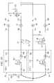
- FIG. 2Dis a common mode circuit diagram showing portions of power sourcing equipment 11 , adapter 12 , and high power powered device 14 illustrated in FIGS. 2A , 2 B, and 2 C. In this view the circuit elements are illustrated with their connections to each other in a single figure. Operation of power delivery system 10 is described with reference to FIG. 2D .
- Power from power source 42may be supplied to port 18 and provided over nodes 50 A and SOB to adapter 12 .
- Standard IEEE power over Ethernet proceduresmay occur, including detection, powered device classification, powering up, and monitoring.
- a voltageis supplied over nodes 50 A and 50 B that is less than approximately ten volts and the resulting current is measured to obtain an overall resistance value.
- the overall resistance valueindicates whether powered device circuitry 110 is present. Only after a valid power device is detected with a valid resistance does the process continue to classification.
- a particular voltage between 20 and 30 voltsis supplied over nodes 50 A and SOB. If the powered device is a valid powered device the current that is drawn will be independent of the voltage supplied in that range of 20 to 30 volts. Thus, if a valid current range is seen when these various voltage levels are provided, the powered device may be classified. After classification, 48 volts, which is the nominal voltage supplied by power sourcing equipment 11 , is supplied over nodes 50 A and 50 B by turning on switch 106 . Monitoring then occurs to determine whether the powered device is removed.
- the above IEEE procedureis a standard procedure for providing power over to a power over Ethernet powered device.
- Port 18operates according to this standard procedure. However, port 20 , may not power up in this manner because switch 118 is open during this detection sequence. However once port 18 is powered such that it is operating at 48 volts (or other suitable power supply voltage), sufficient current flows through resistor 72 to turn on switch 80 . Current flow through resistor 72 is monitored by amplifier 74 , providing an indication of the powered-up status of powered device circuitry 110 . Once switch 80 is turned on, port 20 proceeds to a standard detection phase; however, because of the 48 volts supplied to power device circuitry 110 , diodes 94 and 96 are reverse biased. Therefore port 20 sees resistor 82 but not the resistance of powered device circuitry 110 .
- resistor 82is provided with a resistance level sufficient to result in a valid detection, even though port 20 does not actually see powered device circuitry 110 , and therefore resistor 82 acts to mimic the appearance of a valid power over Ethernet device, even though it does not actually detect a power over Ethernet device. As described above, other detection techniques may be used. Then normal IEEE classification may occur. According to one example, classification for port 20 will default to providing maximum power. Resistors 120 , 122 , 124 , and 126 help to balance the power level supplied by each port 18 and 20 .
- adapter 12provides a mechanism for sensing whether port 18 is providing current to powered device circuitry 110 , and if so, effects a turning on of switch 8 b associated with port 20 .
- resistor 82mimics the resistance of powered device circuitry 110 .
- FIG. 3is a circuit diagram illustrating additional details of the adapter 12 . In particular, pin assignments and connections are illustrated. All signals from port 18 over line 50 are passed to powered device 14 over line 54 . Power is passed to pairs C and D (pins 4 , 5 , 7 , and 8 ) using a transformer that blocks data transfer and permits IEEE 802.3AF detection, classification, and power transfer. This power is tapped from the port 20 interface using a transformer coupling. All pairs of port 20 are properly terminated. A diode 120 is provided in series with resistor 82 in this embodiment. This diode 120 prevents the detection from being valid with an incorrect polarity power supply. The minimal power requirements for the circuits are tapped from the power interface and do not contribute significantly to the budget of power sourcing equipment 11 .
- FIG. 4is a block diagram illustrating a power delivery system 210 according to yet another embodiment of the invention.
- an adapter for supplying power received from two ports of a power supply to a single input of a high power devicewas described. This may be generalized to providing power from N ports to a high power device, as illustrated.
- ports 218 , 220 , and 222provide power over lines 250 , 252 , and 255 to adapter circuitry 212 , which provides power to high power device 214 over line 254 .
- 2A-2Dmay be utilized for N ports by including a current detecting device, such as resistor 72 and amplifier 74 in the adapter portion associated with all ports except the last port and by providing a switch, such as switch 80 in the adapter portion associated with all ports except the first port. In this manner each successive port may be selectively turned on as power is required from high power device 214 , as described above.
- the second and any subsequent portsmay be turned on based on the class provided by the high power powered device.
- An example technique for accomplishing thisincludes permitting power detection and classification on a second port in response to seeing a power demand on the first port.
- Another exampleinvolves the use of an intelligent subcircuit that may snoop the transactions between power sourcing equipment and the powered device on the first port.
- the classwhich may include a class not presently existing, can be discovered by determining what class is being passed between the devices. For example, knowing the port voltage indicates if a class is being performed. Then monitoring the current indicates the class.
- Another exampleincludes snooping a side band protocol to discover the systems class.
- FIG. 5is a schematic diagram illustrating a physical configuration for adapter 12 .
- ports 18 and 20 of power sourcing equipment 11are shown to be adjacent ports of a power supply in which power may be delivered.
- Adapter 12is constructed such that power supplied over output 54 of adapter 12 can result only from the provision of power to adapter 12 from a single power sourcing equipment 11 .
- the input ports 50 and 52 at adapter 12are configured to mate with output ports 18 and 20 of a single power supply. This prevents power from being supplied by an adapter that comes from two different power sources. Supplying power from two different power sources, as opposed to two ports of a given power source, causes reliability and safety concerns.
- FIG. 5illustrates one of many possible physical configurations that may be utilized, including those utilizing two horizontal connections as well as combining together more than two ports.
Landscapes
- Engineering & Computer Science (AREA)
- General Engineering & Computer Science (AREA)
- Theoretical Computer Science (AREA)
- Computer Hardware Design (AREA)
- Physics & Mathematics (AREA)
- General Physics & Mathematics (AREA)
- Power Sources (AREA)
- Small-Scale Networks (AREA)
Abstract
Description
This invention relates generally to power over Ethernet applications and more particularly to a method and system for providing increased power for power over Ethernet applications.
Numerous powered devices utilize power delivered over four-pair Ethernet cables. IEEE has issued a standard, IEEE 802.3af, that specifies methods of power delivery over Ethernet. In particular, the standard describes the use of two of the four pairs to deliver power to a powered device. However, as telecommunication devices adapt to meet new communication demands, such devices may have different power needs, which may include the need for additional power.
One approach described in co-pending application entitled “Improved Power Delivery Over Ethernet Cables,” filed May 13, 2004, and having a Ser. No. 10/845,021, addresses the need for increased power by providing power over all four pairs. However, in some instances it may be desirable to provide increased power using conventional power supplies.
According to one embodiment of the invention, a method for supplying power over Ethernet cables includes determining whether a first port of power sourcing equipment is supplying current to a power over Ethernet powered device in a predetermined current range. The method also includes electrically connecting a second port of the power sourcing equipment to the power over Ethernet device in response to determining that a first port of the power sourcing equipment is supplying current to the power over Ethernet powered device. The method also includes supplying power from the second port to the power over Ethernet powered device.
According to another embodiment of the invention, an apparatus includes a current detection circuit operable to determine whether a first port of power sourcing equipment is supplying current to a power over Ethernet device and a switching circuit operable to receive an indication from the current detection circuit that the first port of the power sourcing equipment is supplying current to a power over Ethernet device and, in response, electrically connect a second port of the power sourcing equipment to the power over Ethernet device. The apparatus also includes a detection circuit operable to mimic a valid power over Ethernet device.
Important technical advantages of certain embodiments of the present invention include the provision of increased power to a single powered device through a plurality of ports from power sourcing equipment. This allows, in some embodiments, for the powering of a high powered power over Ethernet device by standard power sourcing equipment that was not intended to necessarily provide such high levels of power to the powered device. This avoids retrofitting certain systems with specifically-designed power sourcing equipment for such high powered devices. Other technical advantages of the present invention will be readily apparent to ones skilled in the art form the following figures, descriptions, and claims. Moreover, while specific advantages have been enumerated above, various embodiments may include all, some, or none of the enumerated advantages.
For a more complete understanding of the present invention and its advantages, references now made to the following description, taken in conjunction with the accompanying drawings, in which:
According to the teachings of the invention,adapter circuitry 12 receives power from more than one port ofpower sourcing equipment 11 and provides this power to a single powered device, allowing a high power powered device to be powered by conventional power supplies having ports with maximum power outputs that individually cannot meet the power requirements of the high power powered device. As described in co-pending application entitled “Improved Power Delivery Over Ethernet Cables,” filed May 13, 2004, and having a Ser. No. 10/845,021, which is incorporated herein by reference, one method for delivering increased power to power over Ethernet powered devices is to provide power over all data pairs within an Ethernet cable. Traditionally, only half of the pairs are used to transmit power with the other half being used sometimes for data and sometimes not being used at all. According to the teachings of the present invention, it is recognized that certain powered devices requiring increased power may be used in conjunction with power over Ethernet power supplies that are not designed to provide power in such a manner. Thus, an adapter is provided that takes power from multiple ports of a power supply to produce increased power for that powered device.
In one embodiment, high power powereddevice 14 requires more than 12.95 watts, which is the current maximum level typically consumed by power over Ethernet powered devices. Standard power devices16 are standard power over Ethernet devices. Powereddevices 14 and16 may include a telephone, a personal computer, a personal digital assistant, a laptop, a wireless network access point, a docking station, or other device that may be powered over Ethernet lines.
A first line52A oflines 52 is connected to line54C. Line52B is connected to aswitch 80.Switch 80 receives output fromamplifier 74, which is an indicator of the level of current flow throughresistor 72. If the current flow throughresistor 72 is at an appropriate level that is indicative ofport 18 providing power to high power powereddevice 14, this indicates that power may be desired fromport 20. If such is the case, switch80 closes, completing the circuit between lines52A and52B, allowing current to flow. Aresistor 78 is provided in parallel withMOSFET transistor 80. It will be understood that other alternatives to a MOSFET for providing this circuit switching capability may be utilized. As described in greater detail below, aresistor 82 connectinglines device 14. Alternatively,resistor 82 may be replaced with a subcircuit that permits detection and classification. This subcircuit may take the form of that which is normally used in a powered device. One advantage to using such a subcircuit is that any arbitrary power requirement can be accounted for.
Power frompower source 42 may be supplied toport 18 and provided over nodes50A and SOB toadapter 12. Standard IEEE power over Ethernet procedures may occur, including detection, powered device classification, powering up, and monitoring. In general, according to IEEE specifications, during detection, a voltage is supplied over nodes50A and50B that is less than approximately ten volts and the resulting current is measured to obtain an overall resistance value. The overall resistance value indicates whetherpowered device circuitry 110 is present. Only after a valid power device is detected with a valid resistance does the process continue to classification.
In general, according to IEEE specifications, at classification a particular voltage between 20 and 30 volts is supplied over nodes50A and SOB. If the powered device is a valid powered device the current that is drawn will be independent of the voltage supplied in that range of 20 to 30 volts. Thus, if a valid current range is seen when these various voltage levels are provided, the powered device may be classified. After classification, 48 volts, which is the nominal voltage supplied bypower sourcing equipment 11, is supplied over nodes50A and50B by turning onswitch 106. Monitoring then occurs to determine whether the powered device is removed.
The above IEEE procedure is a standard procedure for providing power over to a power over Ethernet powered device.Port 18 operates according to this standard procedure. However,port 20, may not power up in this manner becauseswitch 118 is open during this detection sequence. However onceport 18 is powered such that it is operating at 48 volts (or other suitable power supply voltage), sufficient current flows throughresistor 72 to turn onswitch 80. Current flow throughresistor 72 is monitored byamplifier 74, providing an indication of the powered-up status ofpowered device circuitry 110. Onceswitch 80 is turned on,port 20 proceeds to a standard detection phase; however, because of the 48 volts supplied topower device circuitry 110,diodes port 20 seesresistor 82 but not the resistance ofpowered device circuitry 110. Thus,resistor 82 is provided with a resistance level sufficient to result in a valid detection, even thoughport 20 does not actually seepowered device circuitry 110, and therefore resistor82 acts to mimic the appearance of a valid power over Ethernet device, even though it does not actually detect a power over Ethernet device. As described above, other detection techniques may be used. Then normal IEEE classification may occur. According to one example, classification forport 20 will default to providing maximum power.Resistors port
Thus,adapter 12 provides a mechanism for sensing whetherport 18 is providing current topowered device circuitry 110, and if so, effects a turning on of switch8bassociated withport 20. To allow detection byport 20,resistor 82 mimics the resistance ofpowered device circuitry 110.
It should be noted that the second and any subsequent ports may be turned on based on the class provided by the high power powered device. An example technique for accomplishing this includes permitting power detection and classification on a second port in response to seeing a power demand on the first port. Another example involves the use of an intelligent subcircuit that may snoop the transactions between power sourcing equipment and the powered device on the first port. The class, which may include a class not presently existing, can be discovered by determining what class is being passed between the devices. For example, knowing the port voltage indicates if a class is being performed. Then monitoring the current indicates the class. Another example includes snooping a side band protocol to discover the systems class. One technique for such snooping is described in co-pending application entitled “In-Line Power-Based Common Mode Communications in a Wired Data Telecommunications Network,” filed Oct. 7, 2004 and listing Roger Karam, Frederick Schindler, and Wael Diab as inventors, which is incorporated herein by reference.
Although the present invention has been described with several embodiments, a myriad of changes, variations, alterations, transformations, and modifications may be suggested to one skilled in the art, and it is intended that the present invention encompass such changes, variations, alterations, transformation, and modifications as they fall within the scope of the appended claims.
Claims (31)
1. A method for supplying power over Ethernet comprising:
determining that a first port of power sourcing equipment is supplying current to a power over Ethernet device in a predetermined current range;
in response to determining that a first port of the power sourcing equipment is supplying current to the power over Ethernet device in a predetermined current range, electrically connecting a second port of the power sourcing equipment to the power over Ethernet powered device; and
supplying power from the second port to the power over Ethernet device.
2. The method ofclaim 1 , and further comprising detecting the power over Ethernet device in response to determining that the first port of the power sourcing equipment is supplying current to the power over Ethernet device in a predetermined range.
3. The method ofclaim 2 , and further comprising detecting the power over Ethernet device by determining whether a resistance level seen by the second port is within a predetermined resistance range.
4. The method ofclaim 3 , and further comprising classifying the power over Ethernet device in response to determining whether a resistance level seen by the second port is within a predetermined range.
5. The method ofclaim 1 , wherein determining that a first port of a power supply is supplying current to a power over Ethernet powered device comprises measuring a voltage drop through a resistor disposed between the first port and the power over Ethernet powered device.
6. The method ofclaim 1 , wherein electrically connecting a second port of the power device to the power over Ethernet powered device comprises switching a switch disposed between the second port and the power over Ethernet device.
7. The method ofclaim 6 , wherein the switch is a MOSFET.
8. The method ofclaim 3 , wherein determining that a resistance level seen by the second port is within a predetermined resistance range comprises reverse biasing at least one diode disposed between the second port and the power over Ethernet powered device, thereby isolating the power over Ethernet device from the second port, and exposing the second port to a resistance level within the predetermined resistance range.
9. The method ofclaim 8 , wherein exposing the second port to a resistance level comprises exposing the second port to a resistor having a value approximately equal to a resistance of the power over Ethernet powered device.
10. The method ofclaim 1 , wherein the power over Ethernet device is selected from the group consisting of an IP phone, a computer, a wireless network access point, and a docking station.
11. The method ofclaim 1 , wherein the power over Ethernet powered device requires more than 12.95 watts.
12. An apparatus comprising:
a current detection circuit operable to determine whether a first port of power sourcing equipment is supplying current to a power over Ethernet powered device;
a switching circuit operable to receive an indication from the current detection circuit that the first port of the power sourcing equipment is supplying current to a power over Ethernet powered device, and, in response, electrically connect a second port of the power sourcing equipment to the power over Ethernet powered device; and
a detection circuit operable to mimic a valid power over Ethernet device.
13. The apparatus ofclaim 12 , wherein the detection circuit comprises a resistance element operable to mimic a resistance of the power over Ethernet device that is seen by the second port.
14. The apparatus ofclaim 12 , wherein the current detection system comprises a resistor and an amplifier operable to measure a voltage drop across the resistor.
15. The apparatus ofclaim 12 , wherein the switching circuit comprises a MOSFET.
16. The apparatus ofclaim 13 , wherein the resistance element comprises a resistor.
17. The apparatus ofclaim 16 , wherein the detection circuit comprises at least one reverse-biased diode connected to the resistor such that current is prevented from flowing to the power over Ethernet powered device from the second port but allowed to flow through the resistor from the second port, thereby allowing detection of a valid power over Ethernet powered device by mimicking the resistance of the power over Ethernet powered device.
18. The apparatus ofclaim 12 , wherein the power over Ethernet powered device is selected from the group consisting of an IP phone, a computer, a wireless network access point, and a docking system.
19. The apparatus ofclaim 12 , and further comprising the power over Ethernet powered device and wherein the power over Ethernet powered device is operable to receive power from the first and second ports of the power sourcing equipment.
20. The apparatus ofclaim 12 , wherein the current detection circuit and switching circuit are disposed within a housing having two ports mechanically configured to couple to two adjacent ports of the power sourcing equipment, thereby hindering the provision of power from two independent power supplies.
21. The apparatus ofclaim 20 , wherein the detection circuit is disposed within the housing.
22. An apparatus comprising:
a current detection means for determining whether a first portion of power sourcing equipment is supplying current to a power over Ethernet powered device;
a switching means for receiving an indication from the current detection means that the first port of the power sourcing equipment is supplying current to the power over Ethernet powered device and, in response, electrically connect a second port of the power sourcing equipment to the power over Ethernet powered device; and
a detection means for mimicking a valid power over Ethernet device.
23. The apparatus ofclaim 22 , and further comprising the power over Ethernet powered device, and wherein the power over Ethernet powered device is operable to receive power from the first and second ports of the power sourcing equipment.
24. The apparatus ofclaim 22 , and further comprising a housing means for housing the current detection means and the switching means and for hindering the provision of power from two independent power supplies.
25. The apparatus ofclaim 24 , when the detection means is disposed within the housing means.
26. A power over Ethernet system comprising:
power sourcing equipment having first and second ports operable to provide power;
an adapter for facilitating the delivery of power from the power sourcing equipment comprising:
a current detection circuit operable to determine whether a first port of the power sourcing equipment is supplying current to a power over Ethernet powered device;
a switching circuit operable to receive an indication from the current detection circuit that the first port of the power sourcing equipment is supplying current to a power over Ethernet powered device and, in response, electrically connect the second port of the power sourcing equipment to the power over Ethernet device; and
a detection circuit operable to mimic a valid power over Ethernet powered device; and
the power over Ethernet powered device coupled to the adapter.
27. The power over Ethernet system ofclaim 26 , wherein the power sourcing equipment is operable to classify the power over Ethernet device and selectively supply power over one or both of the first and second ports based on the classification.
28. The power over Ethernet system ofclaim 26 , wherein the power over Ethernet powered device includes at least one diode operable to isolate the second port from the power over Ethernet powered device when the at least one diode is reversed-biased.
29. The power over Ethernet system ofclaim 28 , wherein the power over Ethernet powered device includes at least one input resistor in series with the at least one diode for regulating the amount of current flowing through the diode.
30. The power over Ethernet system ofclaim 26 , wherein the first and second ports each include a diode for providing an AC disconnect.
31. A power over Ethernet system comprising:
a power sourcing equipment means for supplying power;
adapter means for facilitating the delivery of power from the power sourcing equipment means, the adapter means including:
a current detection means for determining that a first part of the power sourcing equipment is supplying current to a power over Ethernet powered device;
a circuit switching means for receiving an indication from the current detection means that the first port of the power sourcing equipment is supplying current to a power over Ethernet powered device and, in response, electrically connect a second port of the power sourcing equipment to the power over Ethernet device; and
a detection means for mimicking a valid power over Ethernet device; and
the power over Ethernet powered device for receiving power from the adapter means.
Priority Applications (1)
| Application Number | Priority Date | Filing Date | Title |
|---|---|---|---|
| US10/998,077US7373528B2 (en) | 2004-11-24 | 2004-11-24 | Increased power for power over Ethernet applications |
Applications Claiming Priority (1)
| Application Number | Priority Date | Filing Date | Title |
|---|---|---|---|
| US10/998,077US7373528B2 (en) | 2004-11-24 | 2004-11-24 | Increased power for power over Ethernet applications |
Publications (2)
| Publication Number | Publication Date |
|---|---|
| US20060112288A1 US20060112288A1 (en) | 2006-05-25 |
| US7373528B2true US7373528B2 (en) | 2008-05-13 |
Family
ID=36462254
Family Applications (1)
| Application Number | Title | Priority Date | Filing Date |
|---|---|---|---|
| US10/998,077Active2025-11-12US7373528B2 (en) | 2004-11-24 | 2004-11-24 | Increased power for power over Ethernet applications |
Country Status (1)
| Country | Link |
|---|---|
| US (1) | US7373528B2 (en) |
Cited By (38)
| Publication number | Priority date | Publication date | Assignee | Title |
|---|---|---|---|---|
| US20060164098A1 (en)* | 2005-01-25 | 2006-07-27 | Linear Technology Corporation | Utilization of power delivered to powered device during detection and classification mode |
| US20060171399A1 (en)* | 2003-10-16 | 2006-08-03 | Alon Ferentz | Detection for high powered devices |
| US20070081549A1 (en)* | 2005-10-12 | 2007-04-12 | Finisar Corporation | Network tap/aggregator configured for power over ethernet operation |
| US20070171966A1 (en)* | 2005-11-15 | 2007-07-26 | Light Greta L | Passive tap and associated system for tapping network data |
| US20070174527A1 (en)* | 2006-01-17 | 2007-07-26 | Broadcom Corporation | Apparatus for sensing an output current in a communications device |
| US20070195719A1 (en)* | 1998-07-28 | 2007-08-23 | Serconet, Ltd. | Local area network of serial intelligent cells |
| US20070220287A1 (en)* | 2006-03-16 | 2007-09-20 | Cmotech Co., Ltd. | Large current supply device for USB terminal device and connection structure for USB terminal device |
| US20070277049A1 (en)* | 2006-05-25 | 2007-11-29 | Foundry Networks, Inc. | System software for managing power allocation to ethernet ports in the absence of mutually exclusive detection and powering cycles in hardware |
| US20070274322A1 (en)* | 2006-05-25 | 2007-11-29 | Foundry Networks, Inc. | Power supply status driven enabling and disabling of power over ethernet software subsystem |
| US20070284946A1 (en)* | 2006-06-10 | 2007-12-13 | Steven Andrew Robbins | Passive Power Combiner for Dual Power over Ethernet Sources |
| US20080042616A1 (en)* | 2006-08-17 | 2008-02-21 | Monks Morgan H | System and Method for Rapidly Charging a USB Device |
| US20080244282A1 (en)* | 2007-03-30 | 2008-10-02 | Foundry Networks, Inc. | Managing Power Allocation To Ethernet Ports In The Absence Of Mutually Exclusive Detection And Powering Cycles In Hardware |
| US20080288794A1 (en)* | 2005-01-04 | 2008-11-20 | Cisco Technology, Inc. | Method and system for managing power delivery for power over ethernet systems |
| US20090121548A1 (en)* | 2007-11-08 | 2009-05-14 | Cisco Technology, Inc. | Dynamic current limits |
| US20090161281A1 (en)* | 2007-12-21 | 2009-06-25 | Broadcom Corporation | Capacitor sharing surge protection circuit |
| US20100007220A1 (en)* | 2008-07-09 | 2010-01-14 | Chung-Peng Lo | Power management system |
| US20100078992A1 (en)* | 2008-09-26 | 2010-04-01 | Silicon Laboratories, Inc. | Circuit device and method of current limit-based disconnect detection |
| US20100237846A1 (en)* | 2009-03-17 | 2010-09-23 | Cisco Technology, Inc. | Controlling inline power at at powered device |
| US20100246786A1 (en)* | 2000-03-20 | 2010-09-30 | Mosaid Technologies Incorporated | Telephone outlet for implementing a local area network over telephone lines and a local area network using such outlets |
| US7809960B2 (en) | 2005-10-12 | 2010-10-05 | Cicchetti Christopher J | Network tap device powered by power over ethernet |
| US7835386B2 (en) | 1999-07-07 | 2010-11-16 | Mosaid Technologies Incorporated | Local area network for distributing data communication, sensing and control signals |
| US8027277B2 (en) | 2005-11-15 | 2011-09-27 | Jds Uniphase Corporation | Passive network tap for tapping network data |
| US8185759B1 (en) | 2008-11-06 | 2012-05-22 | Smsc Holdings S.A.R.L. | Methods and systems for interfacing bus powered devices with host devices providing limited power levels |
| US8214680B1 (en)* | 2009-02-12 | 2012-07-03 | Hewlett-Packard Development Company, L.P. | PoE powered management circuitry using out-of-band data port |
| US20120271477A1 (en)* | 2011-04-25 | 2012-10-25 | Wizlan Ltd. | System And Method For Illumination Using Power Over Ethernet |
| US8332545B1 (en) | 2011-05-31 | 2012-12-11 | Smsc Holdings S.A.R.L. | USB switch which allows primary USB connection in response to USB signaling |
| US8499177B2 (en) | 2011-03-14 | 2013-07-30 | Cisco Technology, Inc. | Discovering a device presence and directing a power signal to the device from a port power controller through at most one of multiple physical ports at a time |
| CN103339581A (en)* | 2010-10-04 | 2013-10-02 | 阿沃森特亨茨维尔公司 | Remote access appliance with backup power system |
| US8565417B2 (en) | 2004-02-16 | 2013-10-22 | Mosaid Technologies Incorporated | Outlet add-on module |
| US8843770B2 (en) | 2011-10-31 | 2014-09-23 | Smsc Holdings S.A.R.L. | Device charging over USB using a plurality of handshakes |
| US9685785B2 (en) | 2008-12-11 | 2017-06-20 | Lattice Semiconductor Corporation | Power delivery over digital interaction interface for video and audio (DiiVA) |
| US9720473B2 (en)* | 2013-04-17 | 2017-08-01 | Pismo Labs Technology Limited | Methods and systems for supplying and receiving power over ethernet |
| US10057073B2 (en) | 2015-01-07 | 2018-08-21 | Microsemi P.O.E. Ltd. | PoE power monitoring arrangement and method |
| US10528112B2 (en) | 2016-09-11 | 2020-01-07 | Microsemi P.O.E. Ltd. | MPS generation system and method |
| US11032353B2 (en) | 2004-01-13 | 2021-06-08 | May Patents Ltd. | Information device |
| US11114936B2 (en) | 2017-09-08 | 2021-09-07 | Hewlett Packard Enterprise Development Lp | Adjusting output voltage of powered device ports |
| US11639776B2 (en) | 2016-02-15 | 2023-05-02 | Molex, Llc | Luminaire |
| US11909540B2 (en)* | 2016-03-03 | 2024-02-20 | Molex, Llc | System and method for power over ethernet control |
Families Citing this family (35)
| Publication number | Priority date | Publication date | Assignee | Title |
|---|---|---|---|---|
| KR101012744B1 (en)* | 2002-10-31 | 2011-02-09 | 록히드 마틴 코포레이션 | Pipeline Accelerators and Related Systems and Methods for Enhanced Computing Architectures |
| US7511515B2 (en)* | 2005-01-25 | 2009-03-31 | Linear Technology Corporation | System for providing power over communication cable having mechanism for determining resistance of communication cable |
| US20060210057A1 (en)* | 2005-01-25 | 2006-09-21 | Linear Technology Corporation | Supplying power over four pairs of conductors in communication cable |
| TWI266504B (en)* | 2005-03-08 | 2006-11-11 | Realtek Semiconductor Corp | Relay set in network device and method thereof |
| US7340620B2 (en)* | 2005-05-10 | 2008-03-04 | Hewlett-Packard Development Company, L.P. | Rapid load reduction for power-over-LAN system using lower and higher priority states for ports |
| US7320078B2 (en)* | 2005-06-03 | 2008-01-15 | Cisco Technology, Inc. | Controlling delivery of power and network communications to a set of devices |
| US20060284840A1 (en)* | 2005-06-15 | 2006-12-21 | Research In Motion Limited | Portable electronic device including pointer and related methods |
| US20070080946A1 (en)* | 2005-10-07 | 2007-04-12 | Research In Motion Limited | Portable electronic device including trackball unit and associated methods |
| US8014412B2 (en)* | 2005-12-12 | 2011-09-06 | Linear Technology Corporation | Power sourcing equipment having bipolar junction transistor for controlling power supply and supporting AC disconnect-detection function |
| US20070288771A1 (en)* | 2006-06-08 | 2007-12-13 | Steven Andrew Robbins | Source Separator for Power over Ethernet Systems |
| US7886165B2 (en)* | 2007-05-24 | 2011-02-08 | Broadcom Corporation | Power management for Power-over-Ethernet-capable switch |
| US20100187903A1 (en)* | 2007-12-17 | 2010-07-29 | Wael William Diab | Method and system for vehicular power distribution utilizing power over ethernet in an aircraft |
| US20090152943A1 (en)* | 2007-12-17 | 2009-06-18 | Wael William Diab | Method and system for vehicular power distribution utilizing power over ethernet |
| US8112641B2 (en) | 2007-12-26 | 2012-02-07 | Cisco Technology, Inc. | Facilitating communication and power transfer between electrically-isolated powered device subsystems |
| US8001403B2 (en)* | 2008-03-14 | 2011-08-16 | Microsoft Corporation | Data center power management utilizing a power policy and a load factor |
| US7737573B2 (en)* | 2008-06-13 | 2010-06-15 | Symbol Technologies, Inc. | Power over ethernet combiner |
| TWI388153B (en)* | 2008-12-12 | 2013-03-01 | Wistron Neweb Corp | Network equipment |
| US20110055598A1 (en)* | 2009-09-02 | 2011-03-03 | Broadcom Corporation | AC Disconnect of Power Over Ethernet Devices |
| DE102011003309A1 (en)* | 2011-01-28 | 2012-08-02 | Siemens Aktiengesellschaft | Network node for automation network i.e. industrial automation network, in e.g. personal computer, has interface electrically connected with data line, which is connected with network terminal, where node transmits data to supply module |
| EP2751951B1 (en)* | 2011-08-31 | 2018-02-28 | Hewlett-Packard Development Company, L.P. | Power drawn by network powered device |
| US9660456B2 (en)* | 2011-10-24 | 2017-05-23 | Linear Technology Corporation | Switching of conductor pair in power over ethernet system |
| US9069539B2 (en)* | 2012-01-20 | 2015-06-30 | Adtran, Inc. | Method and system for furnishing power and data from power sourcing equipment to powered device |
| US9755852B2 (en)* | 2012-05-11 | 2017-09-05 | Fsr Inc. | Power over ethernet to USB adapter |
| CA2845423C (en)* | 2012-12-28 | 2016-08-02 | Rui HUA | Power over ethernet method, apparatus, device, and system |
| US10313138B2 (en) | 2013-08-08 | 2019-06-04 | Signify Holding B.V. | Powered device and power distribution system comprising the powered device |
| TWI505595B (en)* | 2013-11-01 | 2015-10-21 | Wistron Neweb Corp | Power integrated device and power control method thereof |
| JP2016116110A (en)* | 2014-12-16 | 2016-06-23 | 富士通株式会社 | Communication apparatus |
| US9973343B2 (en)* | 2015-04-09 | 2018-05-15 | Sercomm Corporation | Power supply system, power sourcing equipment, and ethernet Y cable |
| WO2016183007A1 (en)* | 2015-05-08 | 2016-11-17 | Igor, Inc. | Power over ethernet system |
| US11804973B2 (en)* | 2016-09-01 | 2023-10-31 | Commscope Technologies Llc | Apparatus and systems for providing DC power using communication networks |
| CN108111316B (en)* | 2016-11-25 | 2020-02-11 | 新华三技术有限公司 | PSE (Power supply Environment) |
| WO2018109567A1 (en)* | 2016-12-12 | 2018-06-21 | Ale Usa Inc. | Powered communication device |
| CN111245628B (en)* | 2020-03-20 | 2024-12-17 | 北京华信傲天网络技术有限公司 | Power receiving equipment and power receiving system supporting power receiving of Ethernet with double network ports |
| US11729008B2 (en)* | 2021-03-12 | 2023-08-15 | Ali Eghbal | Power over ethernet port multiplexer system, apparatus, and method |
| US12416957B2 (en)* | 2023-08-30 | 2025-09-16 | Dell Products L.P. | PoE power aggregation system |
Citations (62)
| Publication number | Priority date | Publication date | Assignee | Title |
|---|---|---|---|---|
| US4131767A (en) | 1976-09-07 | 1978-12-26 | Bell Telephone Laboratories, Incorporated | Echo cancellation in two-wire, two-way data transmission systems |
| US4161719A (en) | 1977-10-04 | 1979-07-17 | Ncr Corporation | System for controlling synchronization in a digital communication system |
| US4232199A (en) | 1978-10-18 | 1980-11-04 | Summa Four, Inc. | Special services add-on for dial pulse activated telephone switching office |
| US4397020A (en) | 1980-09-11 | 1983-08-02 | Bell Telephone Laboratories, Incorporated | Error monitoring in digital transmission systems |
| US4532626A (en) | 1982-07-19 | 1985-07-30 | At&T Bell Laboratories | Collision avoiding system and protocol for a two path multiple access digital communications system |
| US4599494A (en) | 1984-10-10 | 1986-07-08 | Motorola, Inc. | Ring sense telephone tone ringer circuit |
| US4626954A (en) | 1984-09-06 | 1986-12-02 | Eaton Corporation | Solid state power controller with overload protection |
| US4710949A (en) | 1984-07-20 | 1987-12-01 | Om Electronics Systems Corp. | Telephone line fault locating device |
| US4723267A (en) | 1985-06-17 | 1988-02-02 | Octocom Systems, Inc. | Telephone line interface and dialer circuitry for telecommunications equipment |
| US4875223A (en) | 1987-09-08 | 1989-10-17 | Digital Equipment Corporation | Twisted pair adapter |
| US4899204A (en)* | 1987-12-01 | 1990-02-06 | General Electric Company | High voltage switch structure with light responsive diode stack |
| US4922160A (en)* | 1988-08-15 | 1990-05-01 | Pioneer Electronic Corporation | Impedance load driving circuit |
| US4969179A (en) | 1990-01-09 | 1990-11-06 | Edward Kanare | Telephone line monitoring circuit for providing a visual and auditory signal if the telephone line becomes inoperative |
| US5029201A (en) | 1989-04-21 | 1991-07-02 | Alcatel Business Systems | Auto-answer videotex terminal |
| US5034948A (en) | 1988-08-24 | 1991-07-23 | Canon Kabushiki Kaisha | Telephone apparatus system |
| US5056131A (en) | 1990-10-29 | 1991-10-08 | Edward Kanare | Telephone line monitoring circuitry and apparatus |
| USRE33900E (en) | 1980-09-11 | 1992-04-28 | At&T Bell Laboratories | Error monitoring in digital transmission systems |
| US5199049A (en) | 1990-04-27 | 1993-03-30 | At&T Bell Laboratories | Circuit and method of digital carrier detection for burst mode communication systems |
| US5223806A (en) | 1991-08-23 | 1993-06-29 | Digital Equipment Corporation | Method and apparatus for reducing electromagnetic interference and emission associated with computer network interfaces |
| US5311518A (en) | 1990-04-16 | 1994-05-10 | Fujitsu Limited | ISDN interface circuit and system using the same |
| US5321372A (en) | 1993-01-08 | 1994-06-14 | Synoptics Communications, Inc. | Apparatus and method for terminating cables to minimize emissions and susceptibility |
| US5406260A (en) | 1992-12-18 | 1995-04-11 | Chrimar Systems, Inc. | Network security system for detecting removal of electronic equipment |
| US5541957A (en) | 1994-06-15 | 1996-07-30 | National Semiconductor Corporation | Apparatus for transmitting and/or receiving data at different data transfer rates especially in applications such as dual-rate ethernet local-area networks |
| US5574748A (en) | 1989-08-23 | 1996-11-12 | Intellon Corporation | Spread spectrum communications system for network |
| US5655077A (en) | 1994-12-13 | 1997-08-05 | Microsoft Corporation | Method and system for authenticating access to heterogeneous computing services |
| US5659542A (en) | 1995-03-03 | 1997-08-19 | Intecom, Inc. | System and method for signalling and call processing for private and hybrid communications systems including multimedia systems |
| US5671354A (en) | 1995-02-28 | 1997-09-23 | Hitachi, Ltd. | Method of assisting server access by use of user authentication information held in one of servers and a method of assisting management user account for use of servers |
| US5684950A (en) | 1996-09-23 | 1997-11-04 | Lockheed Martin Corporation | Method and system for authenticating users to multiple computer servers via a single sign-on |
| US5796185A (en) | 1996-10-15 | 1998-08-18 | Sony Corporation | Circuit card present sense and protective power supply inhibit for airborne application of ATM switch unit |
| US5802042A (en) | 1996-06-28 | 1998-09-01 | Cisco Systems, Inc. | Autosensing LMI protocols in frame relay networks |
| US5815665A (en) | 1996-04-03 | 1998-09-29 | Microsoft Corporation | System and method for providing trusted brokering services over a distributed network |
| US5918016A (en) | 1997-06-10 | 1999-06-29 | Texas Instruments Incorporated | System with program for automating protocol assignments when newly connected to varing computer network configurations |
| US5944824A (en) | 1997-04-30 | 1999-08-31 | Mci Communications Corporation | System and method for single sign-on to a plurality of network elements |
| US5947773A (en) | 1997-09-26 | 1999-09-07 | Cisco Technology, Inc. | Connector with ESD protection |
| WO1999053408A1 (en) | 1998-04-14 | 1999-10-21 | Juno Online Services, Inc. | Method and apparatus to control a client in a communications network |
| US5994998A (en) | 1997-05-29 | 1999-11-30 | 3Com Corporation | Power transfer apparatus for concurrently transmitting data and power over data wires |
| US6011910A (en) | 1997-04-08 | 2000-01-04 | 3Com Corporation | Supporting authentication across multiple network access servers |
| US6021496A (en) | 1997-07-07 | 2000-02-01 | International Business Machines Corporation | User authentication from non-native server domains in a computer network |
| US6047376A (en) | 1996-10-18 | 2000-04-04 | Toshiba Information Systems (Japan) Corporation | Client-server system, server access authentication method, memory medium stores server-access authentication programs, and issuance device which issues the memory medium contents |
| US6092196A (en) | 1997-11-25 | 2000-07-18 | Nortel Networks Limited | HTTP distributed remote user authentication system |
| US6115468A (en) | 1998-03-26 | 2000-09-05 | Cisco Technology, Inc. | Power feed for Ethernet telephones via Ethernet link |
| US6134666A (en) | 1998-03-12 | 2000-10-17 | Cisco Technology, Inc. | Power supervisor for electronic modular system |
| US6218930B1 (en) | 1999-03-10 | 2001-04-17 | Merlot Communications | Apparatus and method for remotely powering access equipment over a 10/100 switched ethernet network |
| US6253330B1 (en)* | 1999-02-17 | 2001-06-26 | Lucent Technologies Inc. | Redundant regulated power supply system with monitoring of the backup power supply |
| US6283789B1 (en)* | 2000-03-16 | 2001-09-04 | Shui Chuan Tsai | Data and power transmitting cable system |
| US6310781B1 (en) | 1999-03-31 | 2001-10-30 | Cisco Technology, Inc. | Connection pin layout for connecting integrated magnetics modules to a printed circuit board |
| US20010040486A1 (en)* | 1999-03-08 | 2001-11-15 | Elias Bonaventure Kpodzo | High power combiner apparatus |
| US6347949B1 (en) | 2000-06-30 | 2002-02-19 | Cisco Technology Inc. | AC/DC power accommodation method and apparatus for networking/telecommunications devices |
| US20020063584A1 (en) | 2000-11-29 | 2002-05-30 | James Molenda | Unpowered twisted pair loopback circuit for differential mode signaling |
| US6472884B1 (en)* | 1999-10-04 | 2002-10-29 | Helmut Brockhaus | Adapter circuit system for a measuring device |
| US6526515B1 (en)* | 1996-11-04 | 2003-02-25 | Mobility Electronics Inc. | Remote pluggable system having bays for attachment of computer peripherals |
| US6535983B1 (en)* | 1999-11-08 | 2003-03-18 | 3Com Corporation | System and method for signaling and detecting request for power over ethernet |
| US6539484B1 (en)* | 1997-12-18 | 2003-03-25 | Intel Corporation | Configurable power distribution circuit |
| US6541878B1 (en) | 2000-07-19 | 2003-04-01 | Cisco Technology, Inc. | Integrated RJ-45 magnetics with phantom power provision |
| US6643566B1 (en)* | 1999-01-12 | 2003-11-04 | Powerdsine Ltd. | System for power delivery over data communication cabling infrastructure |
| US6762675B1 (en) | 1999-09-27 | 2004-07-13 | Cisco Technology, Inc. | Method and apparatus for remote powering of device connected to network |
| US20040156496A1 (en) | 2003-02-06 | 2004-08-12 | Cisco Technology, Inc. A California Corporation | Enabling cisco legacy power to support IEEE 802.3 AF standard power |
| US6804351B1 (en) | 2000-11-09 | 2004-10-12 | Cisco Technology, Inc. | Method and apparatus for detecting a compatible phantom powered device using common mode signaling |
| US20040218324A1 (en)* | 2002-04-10 | 2004-11-04 | Ferentz Alon Zeev | Active local area network connector with line interogation |
| US20050080516A1 (en)* | 2002-10-15 | 2005-04-14 | David Pincu | Power over ethernet switch node for use in power pooling |
| US20050085212A1 (en)* | 2003-10-16 | 2005-04-21 | Arkadiy Peker | High power architecture for power over Ethernet |
| US6894405B2 (en)* | 2001-12-31 | 2005-05-17 | Giga-Byte Technology Co., Ltd. | Facility for supplying spare or auxiliary power supply to processor device |
- 2004
- 2004-11-24USUS10/998,077patent/US7373528B2/enactiveActive
Patent Citations (67)
| Publication number | Priority date | Publication date | Assignee | Title |
|---|---|---|---|---|
| US4131767A (en) | 1976-09-07 | 1978-12-26 | Bell Telephone Laboratories, Incorporated | Echo cancellation in two-wire, two-way data transmission systems |
| US4161719A (en) | 1977-10-04 | 1979-07-17 | Ncr Corporation | System for controlling synchronization in a digital communication system |
| US4232199A (en) | 1978-10-18 | 1980-11-04 | Summa Four, Inc. | Special services add-on for dial pulse activated telephone switching office |
| USRE33900E (en) | 1980-09-11 | 1992-04-28 | At&T Bell Laboratories | Error monitoring in digital transmission systems |
| US4397020A (en) | 1980-09-11 | 1983-08-02 | Bell Telephone Laboratories, Incorporated | Error monitoring in digital transmission systems |
| US4532626A (en) | 1982-07-19 | 1985-07-30 | At&T Bell Laboratories | Collision avoiding system and protocol for a two path multiple access digital communications system |
| US4710949A (en) | 1984-07-20 | 1987-12-01 | Om Electronics Systems Corp. | Telephone line fault locating device |
| US4626954A (en) | 1984-09-06 | 1986-12-02 | Eaton Corporation | Solid state power controller with overload protection |
| US4599494A (en) | 1984-10-10 | 1986-07-08 | Motorola, Inc. | Ring sense telephone tone ringer circuit |
| US4723267A (en) | 1985-06-17 | 1988-02-02 | Octocom Systems, Inc. | Telephone line interface and dialer circuitry for telecommunications equipment |
| US4875223A (en) | 1987-09-08 | 1989-10-17 | Digital Equipment Corporation | Twisted pair adapter |
| US4899204A (en)* | 1987-12-01 | 1990-02-06 | General Electric Company | High voltage switch structure with light responsive diode stack |
| US4922160A (en)* | 1988-08-15 | 1990-05-01 | Pioneer Electronic Corporation | Impedance load driving circuit |
| US5034948A (en) | 1988-08-24 | 1991-07-23 | Canon Kabushiki Kaisha | Telephone apparatus system |
| US5029201A (en) | 1989-04-21 | 1991-07-02 | Alcatel Business Systems | Auto-answer videotex terminal |
| US5574748A (en) | 1989-08-23 | 1996-11-12 | Intellon Corporation | Spread spectrum communications system for network |
| US4969179A (en) | 1990-01-09 | 1990-11-06 | Edward Kanare | Telephone line monitoring circuit for providing a visual and auditory signal if the telephone line becomes inoperative |
| US5311518A (en) | 1990-04-16 | 1994-05-10 | Fujitsu Limited | ISDN interface circuit and system using the same |
| US5199049A (en) | 1990-04-27 | 1993-03-30 | At&T Bell Laboratories | Circuit and method of digital carrier detection for burst mode communication systems |
| US5056131A (en) | 1990-10-29 | 1991-10-08 | Edward Kanare | Telephone line monitoring circuitry and apparatus |
| US5223806A (en) | 1991-08-23 | 1993-06-29 | Digital Equipment Corporation | Method and apparatus for reducing electromagnetic interference and emission associated with computer network interfaces |
| US5406260A (en) | 1992-12-18 | 1995-04-11 | Chrimar Systems, Inc. | Network security system for detecting removal of electronic equipment |
| US5321372A (en) | 1993-01-08 | 1994-06-14 | Synoptics Communications, Inc. | Apparatus and method for terminating cables to minimize emissions and susceptibility |
| US5541957A (en) | 1994-06-15 | 1996-07-30 | National Semiconductor Corporation | Apparatus for transmitting and/or receiving data at different data transfer rates especially in applications such as dual-rate ethernet local-area networks |
| US5799040A (en) | 1994-06-15 | 1998-08-25 | National Semiconductor Corporation | Method for transmitting and/or receiving data at different data transfer rates especially in applications such as dual-rate ethernet local-area networks |
| US5655077A (en) | 1994-12-13 | 1997-08-05 | Microsoft Corporation | Method and system for authenticating access to heterogeneous computing services |
| US5671354A (en) | 1995-02-28 | 1997-09-23 | Hitachi, Ltd. | Method of assisting server access by use of user authentication information held in one of servers and a method of assisting management user account for use of servers |
| US5659542A (en) | 1995-03-03 | 1997-08-19 | Intecom, Inc. | System and method for signalling and call processing for private and hybrid communications systems including multimedia systems |
| US5815665A (en) | 1996-04-03 | 1998-09-29 | Microsoft Corporation | System and method for providing trusted brokering services over a distributed network |
| US5802042A (en) | 1996-06-28 | 1998-09-01 | Cisco Systems, Inc. | Autosensing LMI protocols in frame relay networks |
| US5684950A (en) | 1996-09-23 | 1997-11-04 | Lockheed Martin Corporation | Method and system for authenticating users to multiple computer servers via a single sign-on |
| US5796185A (en) | 1996-10-15 | 1998-08-18 | Sony Corporation | Circuit card present sense and protective power supply inhibit for airborne application of ATM switch unit |
| US6047376A (en) | 1996-10-18 | 2000-04-04 | Toshiba Information Systems (Japan) Corporation | Client-server system, server access authentication method, memory medium stores server-access authentication programs, and issuance device which issues the memory medium contents |
| US6526515B1 (en)* | 1996-11-04 | 2003-02-25 | Mobility Electronics Inc. | Remote pluggable system having bays for attachment of computer peripherals |
| US6011910A (en) | 1997-04-08 | 2000-01-04 | 3Com Corporation | Supporting authentication across multiple network access servers |
| US5944824A (en) | 1997-04-30 | 1999-08-31 | Mci Communications Corporation | System and method for single sign-on to a plurality of network elements |
| US6140911A (en) | 1997-05-29 | 2000-10-31 | 3Com Corporation | Power transfer apparatus for concurrently transmitting data and power over data wires |
| US5994998A (en) | 1997-05-29 | 1999-11-30 | 3Com Corporation | Power transfer apparatus for concurrently transmitting data and power over data wires |
| US5918016A (en) | 1997-06-10 | 1999-06-29 | Texas Instruments Incorporated | System with program for automating protocol assignments when newly connected to varing computer network configurations |
| US6021496A (en) | 1997-07-07 | 2000-02-01 | International Business Machines Corporation | User authentication from non-native server domains in a computer network |
| US5947773A (en) | 1997-09-26 | 1999-09-07 | Cisco Technology, Inc. | Connector with ESD protection |
| US6092196A (en) | 1997-11-25 | 2000-07-18 | Nortel Networks Limited | HTTP distributed remote user authentication system |
| US6539484B1 (en)* | 1997-12-18 | 2003-03-25 | Intel Corporation | Configurable power distribution circuit |
| US6134666A (en) | 1998-03-12 | 2000-10-17 | Cisco Technology, Inc. | Power supervisor for electronic modular system |
| US6308240B1 (en) | 1998-03-12 | 2001-10-23 | Cisco Technology, Inc. | Power management system for modular electronics |
| US6115468A (en) | 1998-03-26 | 2000-09-05 | Cisco Technology, Inc. | Power feed for Ethernet telephones via Ethernet link |
| US6295356B1 (en) | 1998-03-26 | 2001-09-25 | Cisco Technology, Inc. | Power feed for network devices |
| WO1999053408A1 (en) | 1998-04-14 | 1999-10-21 | Juno Online Services, Inc. | Method and apparatus to control a client in a communications network |
| US6643566B1 (en)* | 1999-01-12 | 2003-11-04 | Powerdsine Ltd. | System for power delivery over data communication cabling infrastructure |
| US6253330B1 (en)* | 1999-02-17 | 2001-06-26 | Lucent Technologies Inc. | Redundant regulated power supply system with monitoring of the backup power supply |
| US20010040486A1 (en)* | 1999-03-08 | 2001-11-15 | Elias Bonaventure Kpodzo | High power combiner apparatus |
| US6218930B1 (en) | 1999-03-10 | 2001-04-17 | Merlot Communications | Apparatus and method for remotely powering access equipment over a 10/100 switched ethernet network |
| US6310781B1 (en) | 1999-03-31 | 2001-10-30 | Cisco Technology, Inc. | Connection pin layout for connecting integrated magnetics modules to a printed circuit board |
| US6762675B1 (en) | 1999-09-27 | 2004-07-13 | Cisco Technology, Inc. | Method and apparatus for remote powering of device connected to network |
| US6472884B1 (en)* | 1999-10-04 | 2002-10-29 | Helmut Brockhaus | Adapter circuit system for a measuring device |
| US6535983B1 (en)* | 1999-11-08 | 2003-03-18 | 3Com Corporation | System and method for signaling and detecting request for power over ethernet |
| US6283789B1 (en)* | 2000-03-16 | 2001-09-04 | Shui Chuan Tsai | Data and power transmitting cable system |
| US6347949B1 (en) | 2000-06-30 | 2002-02-19 | Cisco Technology Inc. | AC/DC power accommodation method and apparatus for networking/telecommunications devices |
| US6541878B1 (en) | 2000-07-19 | 2003-04-01 | Cisco Technology, Inc. | Integrated RJ-45 magnetics with phantom power provision |
| US6804351B1 (en) | 2000-11-09 | 2004-10-12 | Cisco Technology, Inc. | Method and apparatus for detecting a compatible phantom powered device using common mode signaling |
| US20020063584A1 (en) | 2000-11-29 | 2002-05-30 | James Molenda | Unpowered twisted pair loopback circuit for differential mode signaling |
| US6894405B2 (en)* | 2001-12-31 | 2005-05-17 | Giga-Byte Technology Co., Ltd. | Facility for supplying spare or auxiliary power supply to processor device |
| US20040218324A1 (en)* | 2002-04-10 | 2004-11-04 | Ferentz Alon Zeev | Active local area network connector with line interogation |
| US7040926B2 (en)* | 2002-04-10 | 2006-05-09 | Powerdsine, Ltd. | Local area network connector for use as a separator |
| US20050080516A1 (en)* | 2002-10-15 | 2005-04-14 | David Pincu | Power over ethernet switch node for use in power pooling |
| US20040156496A1 (en) | 2003-02-06 | 2004-08-12 | Cisco Technology, Inc. A California Corporation | Enabling cisco legacy power to support IEEE 802.3 AF standard power |
| US20050085212A1 (en)* | 2003-10-16 | 2005-04-21 | Arkadiy Peker | High power architecture for power over Ethernet |
Non-Patent Citations (19)
| Title |
|---|
| "33. Data Terminal Equipment (DTE) Power via Media Dependent Interface (MDI)", Draft Supplement to IEEE Standard 802.3 (IEEE Draft P802.3af/D3.2), Sep. 5, 2002. |
| "Amendment: Data Terminal Equipment (DTE) Power via Media Dependent Interface (MDI)", IEEE Draft P802.3af/D4.3, (IEEE Standards Department, Draft Amendment 802-3-2002), Apr. 2003. |
| "Data Terminal Equipment (DTE) Power via Media Dependent Interface (MDI)", IEEE P802.3af/D3.01 (Revision of IEEE Std. 802.3-2000), May 2002. |
| "IEEE Standards"; 802.3af(TM); IEEE Computer Society, The Institute of Electrical and Electronics Engineers, Inc., Jun. 18, 2003. |
| Cafiero, et al. "Method and Apparatus for Remote Powering of Device Connected to Network"-U.S. Appl. No. 10/836,923, pp. 1-16, Apr. 29, 2004. |
| Daniel C. Biederman, "Inline Power Based Device Communications"-U.S. Appl. No. 10/651,596, pp. 1-27, Aug. 29, 2003. |
| Daniel Dove, Powerpoint Presentation, "Power over the DTE", Jan. 2000. |
| Hugh Barrass, "Multi-Pair Aggregate Power Distribution"-U.S. Appl. No. 10/287,886, pp. 1-25, Nov. 4, 2002. |
| IEEE Draft P802.3af/D3.0; IEEE Computer Society, The Institute of Electrical and Electronics Engineers, Inc., 2001. |
| IEEE Draft P802.3af/D3.01; IEEE Computer Society, The Institute of Electrical and Electronics Engineers, Inc., 2001. |
| IEEE Draft P802.3af/D3.1; IEEE Computer Society, The Institute of Electrical and Electronics Engineers, Inc., 2002. |
| IEEE Draft P802.3af/D3.2; IEEE Computer Society, The Institute of Electrical and Electronics Engineers, Inc., 2002. |
| IEEE Draft P802.3af/D4.0; IEEE Computer Society, The Institute of Electrical and Electronics Engineers, Inc., 2002. |
| IEEE Draft P802.3af/D4.01; IEEE Computer Society, The Institute of Electrical and Electronics Engineers, Inc., 2003. |
| James Garrett, "Making the Most Out of 802.3af", Dec. 30, 2003, D&R Industry Articles, http://www.us.design-reuse.com/articles/article6889.html.* |
| Jeffrey D. Provost, "Inline Power Control"-U.S. Appl. No. 10/618,211, pp. 1-15, Jul. 11, 2003. |
| Kiss, Peter (candidate), "Chapter 3, Cascaded Delta-Sigma ADCs", Thesis; "Politehnica" University of Timisoara; cover page plus pp. 45-71, Aug. 20, 1999 revised: Dec. 31, 1999. |
| Robert Muir, Powerpoint Presentation: "Update on Diode Discovery Process", May 2000. |
| Roger A. Karam, "Method and Apparatus for Detecting a Compatible Phantom Powered Device Using Common Mode Signaling"-U.S. Appl. No. 10/855,212, pp. 1-29, May 26, 2004. |
Cited By (90)
| Publication number | Priority date | Publication date | Assignee | Title |
|---|---|---|---|---|
| US8867523B2 (en) | 1998-07-28 | 2014-10-21 | Conversant Intellectual Property Management Incorporated | Local area network of serial intelligent cells |
| US7852874B2 (en) | 1998-07-28 | 2010-12-14 | Mosaid Technologies Incorporated | Local area network of serial intelligent cells |
| US7969917B2 (en) | 1998-07-28 | 2011-06-28 | Mosaid Technologies Incorporated | Local area network of serial intelligent cells |
| US8885659B2 (en) | 1998-07-28 | 2014-11-11 | Conversant Intellectual Property Management Incorporated | Local area network of serial intelligent cells |
| US8908673B2 (en) | 1998-07-28 | 2014-12-09 | Conversant Intellectual Property Management Incorporated | Local area network of serial intelligent cells |
| US20070195719A1 (en)* | 1998-07-28 | 2007-08-23 | Serconet, Ltd. | Local area network of serial intelligent cells |
| US8885660B2 (en) | 1998-07-28 | 2014-11-11 | Conversant Intellectual Property Management Incorporated | Local area network of serial intelligent cells |
| US8325636B2 (en) | 1998-07-28 | 2012-12-04 | Mosaid Technologies Incorporated | Local area network of serial intelligent cells |
| US7830858B2 (en) | 1998-07-28 | 2010-11-09 | Mosaid Technologies Incorporated | Local area network of serial intelligent cells |
| US7835386B2 (en) | 1999-07-07 | 2010-11-16 | Mosaid Technologies Incorporated | Local area network for distributing data communication, sensing and control signals |
| US8121132B2 (en) | 1999-07-07 | 2012-02-21 | Mosaid Technologies Incorporated | Local area network for distributing data communication, sensing and control signals |
| US8582598B2 (en) | 1999-07-07 | 2013-11-12 | Mosaid Technologies Incorporated | Local area network for distributing data communication, sensing and control signals |
| US8363797B2 (en) | 2000-03-20 | 2013-01-29 | Mosaid Technologies Incorporated | Telephone outlet for implementing a local area network over telephone lines and a local area network using such outlets |
| US8855277B2 (en) | 2000-03-20 | 2014-10-07 | Conversant Intellectual Property Managment Incorporated | Telephone outlet for implementing a local area network over telephone lines and a local area network using such outlets |
| US20100246786A1 (en)* | 2000-03-20 | 2010-09-30 | Mosaid Technologies Incorporated | Telephone outlet for implementing a local area network over telephone lines and a local area network using such outlets |
| US20060171399A1 (en)* | 2003-10-16 | 2006-08-03 | Alon Ferentz | Detection for high powered devices |
| US7593756B2 (en)* | 2003-10-16 | 2009-09-22 | Microsemi Corp.—Analog Mixed Signal Group Ltd. | Detection for high powered devices |
| US11032353B2 (en) | 2004-01-13 | 2021-06-08 | May Patents Ltd. | Information device |
| US8565417B2 (en) | 2004-02-16 | 2013-10-22 | Mosaid Technologies Incorporated | Outlet add-on module |
| US20080288794A1 (en)* | 2005-01-04 | 2008-11-20 | Cisco Technology, Inc. | Method and system for managing power delivery for power over ethernet systems |
| US8082457B2 (en)* | 2005-01-04 | 2011-12-20 | Cisco Technology, Inc. | Data communications device for communicating with and concurrently providing power to a set of powerable devices |
| US20060164098A1 (en)* | 2005-01-25 | 2006-07-27 | Linear Technology Corporation | Utilization of power delivered to powered device during detection and classification mode |
| US7809960B2 (en) | 2005-10-12 | 2010-10-05 | Cicchetti Christopher J | Network tap device powered by power over ethernet |
| US20070081549A1 (en)* | 2005-10-12 | 2007-04-12 | Finisar Corporation | Network tap/aggregator configured for power over ethernet operation |
| US7809476B2 (en)* | 2005-10-12 | 2010-10-05 | Cicchetti Christopher J | Network tap/aggregator configured for power over ethernet operation |
| US7860034B2 (en) | 2005-11-15 | 2010-12-28 | Light Greta L | Receive only physical interface device IC used in a passive network tap |
| US20080013467A1 (en)* | 2005-11-15 | 2008-01-17 | Finisar Corporation | Passive Network Tap With Digital Signal Processing for Separating Signals |
| US20080014879A1 (en)* | 2005-11-15 | 2008-01-17 | Finisar Corporation | Receive Only Physical Interface Device IC Used In A Passive Network Tap |
| US8027277B2 (en) | 2005-11-15 | 2011-09-27 | Jds Uniphase Corporation | Passive network tap for tapping network data |
| US7860033B2 (en) | 2005-11-15 | 2010-12-28 | Light Greta L | Passive network tap with bidirectional coupler and associated splitting methods |
| US20070253349A1 (en)* | 2005-11-15 | 2007-11-01 | Finisar Corporation | Passive Network Tap With Bidirectional Coupler and Associated Splitting Methods |
| US7778207B2 (en) | 2005-11-15 | 2010-08-17 | Light Greta L | Passive tap and associated system for tapping network data |
| US7787400B2 (en) | 2005-11-15 | 2010-08-31 | Light Greta L | Passive network tap with digital signal processing for separating signals |
| US20070171966A1 (en)* | 2005-11-15 | 2007-07-26 | Light Greta L | Passive tap and associated system for tapping network data |
| US7782094B2 (en)* | 2006-01-17 | 2010-08-24 | Broadcom Corporation | Apparatus for sensing an output current in a communications device |
| US20080040625A1 (en)* | 2006-01-17 | 2008-02-14 | Broadcom Corporation | Apparatus and method for monitoring for a maintain power signature (MPS) of a powered devide (PD) in a power source equipment (PSE) controller |
| US20070174527A1 (en)* | 2006-01-17 | 2007-07-26 | Broadcom Corporation | Apparatus for sensing an output current in a communications device |
| US8432142B2 (en) | 2006-01-17 | 2013-04-30 | Broadcom Corporation | Power over ethernet controller integrated circuit architecture |
| US20070206774A1 (en)* | 2006-01-17 | 2007-09-06 | Broadcom Corporation | Apparatus and method for classifying a powered device (PD) in a power source equipment (PSE) controller |
| US20100257381A1 (en)* | 2006-01-17 | 2010-10-07 | Broadcom Corporation | Apparatus and Method for Multi-Point Detection in Power-Over-Ethernet Detection Mode |
| US9189043B2 (en) | 2006-01-17 | 2015-11-17 | Broadcom Corporation | Apparatus and method for multipoint detection in power-over-ethernet detection mode |
| US7863871B2 (en) | 2006-01-17 | 2011-01-04 | Broadcom Corporation | Apparatus and method for monitoring for a maintain power signature (MPS) of a powered device (PD) in a power source equipment (PSE) controller |
| US8782442B2 (en) | 2006-01-17 | 2014-07-15 | Broadcom Corporation | Apparatus and method for multi-point detection in power-over-Ethernet detection mode |
| US7973567B2 (en) | 2006-01-17 | 2011-07-05 | Broadcom Corporation | Apparatus for sensing an output current in a communications device |
| US7936546B2 (en) | 2006-01-17 | 2011-05-03 | Broadcom Corporation | Apparatus and method for classifying a powered device (PD) in a power source equipment (PSE) controller |
| US20070220287A1 (en)* | 2006-03-16 | 2007-09-20 | Cmotech Co., Ltd. | Large current supply device for USB terminal device and connection structure for USB terminal device |
| US7631201B2 (en)* | 2006-05-25 | 2009-12-08 | Foundry Networks, Inc. | System software for managing power allocation to Ethernet ports in the absence of mutually exclusive detection and powering cycles in hardware |
| US8001397B2 (en) | 2006-05-25 | 2011-08-16 | Foundry Networks, Llc | System software for managing power allocation to Ethernet ports in the absence of mutually exclusive detection and powering cycles in hardware |
| US20070274322A1 (en)* | 2006-05-25 | 2007-11-29 | Foundry Networks, Inc. | Power supply status driven enabling and disabling of power over ethernet software subsystem |
| US20070277049A1 (en)* | 2006-05-25 | 2007-11-29 | Foundry Networks, Inc. | System software for managing power allocation to ethernet ports in the absence of mutually exclusive detection and powering cycles in hardware |
| US20100299544A1 (en)* | 2006-05-25 | 2010-11-25 | Foundry Networks, Inc. | Enabling/Disabling Power-Over-Ethernet Software Subsystem In Response To Power Supply Status |
| US20100049999A1 (en)* | 2006-05-25 | 2010-02-25 | Foundry Networks, Inc. | System Software For Managing Power Allocation To Ethernet Ports In The Absence of Mutually Exclusive Detection And Powering Cycles In Hardware |
| US7774628B2 (en)* | 2006-05-25 | 2010-08-10 | Foundry Networks, Inc. | Enabling/disabling power-over-ethernet software subsystem in response to power supply status |
| US20070284946A1 (en)* | 2006-06-10 | 2007-12-13 | Steven Andrew Robbins | Passive Power Combiner for Dual Power over Ethernet Sources |
| US20080042616A1 (en)* | 2006-08-17 | 2008-02-21 | Monks Morgan H | System and Method for Rapidly Charging a USB Device |
| US7631111B2 (en)* | 2006-08-17 | 2009-12-08 | Standard Microsystems Corporation | System method for rapidly charging USB device's battery wherein USB device requests charging the battery at a higher power level |
| US8683239B2 (en) | 2007-03-30 | 2014-03-25 | Foundry Networks, Llc | Managing power allocation to Ethernet ports in the absence of mutually exclusive detection and powering cycles in hardware |
| US8250381B2 (en) | 2007-03-30 | 2012-08-21 | Brocade Communications Systems, Inc. | Managing power allocation to ethernet ports in the absence of mutually exclusive detection and powering cycles in hardware |
| US20080244282A1 (en)* | 2007-03-30 | 2008-10-02 | Foundry Networks, Inc. | Managing Power Allocation To Ethernet Ports In The Absence Of Mutually Exclusive Detection And Powering Cycles In Hardware |
| US7902694B2 (en) | 2007-11-08 | 2011-03-08 | Cisco Technology, Inc. | Dynamic current limits |
| US20090121548A1 (en)* | 2007-11-08 | 2009-05-14 | Cisco Technology, Inc. | Dynamic current limits |
| US7679878B2 (en) | 2007-12-21 | 2010-03-16 | Broadcom Corporation | Capacitor sharing surge protection circuit |
| US8027138B2 (en) | 2007-12-21 | 2011-09-27 | Broadcom Corporation | Capacitor sharing surge protection circuit |
| US20090161281A1 (en)* | 2007-12-21 | 2009-06-25 | Broadcom Corporation | Capacitor sharing surge protection circuit |
| US7872378B2 (en)* | 2008-07-09 | 2011-01-18 | Chung-Peng Lo | Power management system |
| US20100007220A1 (en)* | 2008-07-09 | 2010-01-14 | Chung-Peng Lo | Power management system |
| US8716886B2 (en) | 2008-09-26 | 2014-05-06 | Silicon Laboratories Inc. | Circuit device and method of current limit-based disconnect detection |
| US20100078992A1 (en)* | 2008-09-26 | 2010-04-01 | Silicon Laboratories, Inc. | Circuit device and method of current limit-based disconnect detection |
| US8185759B1 (en) | 2008-11-06 | 2012-05-22 | Smsc Holdings S.A.R.L. | Methods and systems for interfacing bus powered devices with host devices providing limited power levels |
| US9685785B2 (en) | 2008-12-11 | 2017-06-20 | Lattice Semiconductor Corporation | Power delivery over digital interaction interface for video and audio (DiiVA) |
| US8214680B1 (en)* | 2009-02-12 | 2012-07-03 | Hewlett-Packard Development Company, L.P. | PoE powered management circuitry using out-of-band data port |
| US8049484B2 (en) | 2009-03-17 | 2011-11-01 | Cisco Technology, Inc. | Controlling inline power at a powered device |
| US20100237846A1 (en)* | 2009-03-17 | 2010-09-23 | Cisco Technology, Inc. | Controlling inline power at at powered device |
| CN103339581A (en)* | 2010-10-04 | 2013-10-02 | 阿沃森特亨茨维尔公司 | Remote access appliance with backup power system |
| CN103339581B (en)* | 2010-10-04 | 2016-01-20 | 阿沃森特亨茨维尔公司 | There is the remote access equipment of standby power system |
| US10437302B2 (en) | 2011-03-14 | 2019-10-08 | Cisco Technology, Inc. | Directing a power signal from a port power controller to one of multiple physical ports |
| US9501122B2 (en) | 2011-03-14 | 2016-11-22 | Cisco Technology, Inc | Directing a power signal from a port power controller to one of multiple physical ports |
| US8499177B2 (en) | 2011-03-14 | 2013-07-30 | Cisco Technology, Inc. | Discovering a device presence and directing a power signal to the device from a port power controller through at most one of multiple physical ports at a time |
| US20120271477A1 (en)* | 2011-04-25 | 2012-10-25 | Wizlan Ltd. | System And Method For Illumination Using Power Over Ethernet |
| US8880748B2 (en) | 2011-05-31 | 2014-11-04 | Smsc Holdings S.À.R.L. | Switching system which allows primary USB connection in response to USB signaling |
| US8332545B1 (en) | 2011-05-31 | 2012-12-11 | Smsc Holdings S.A.R.L. | USB switch which allows primary USB connection in response to USB signaling |
| US8843770B2 (en) | 2011-10-31 | 2014-09-23 | Smsc Holdings S.A.R.L. | Device charging over USB using a plurality of handshakes |
| US10386902B2 (en) | 2013-04-17 | 2019-08-20 | Pismo Labs Technology Limited | Methods and systems for supplying and receiving power over ethernet |
| US10884466B2 (en) | 2013-04-17 | 2021-01-05 | Pismo Labs Technology Limited | Methods and systems for supplying and receiving power over ethernet |
| US9720473B2 (en)* | 2013-04-17 | 2017-08-01 | Pismo Labs Technology Limited | Methods and systems for supplying and receiving power over ethernet |
| US10057073B2 (en) | 2015-01-07 | 2018-08-21 | Microsemi P.O.E. Ltd. | PoE power monitoring arrangement and method |
| US11639776B2 (en) | 2016-02-15 | 2023-05-02 | Molex, Llc | Luminaire |
| US11909540B2 (en)* | 2016-03-03 | 2024-02-20 | Molex, Llc | System and method for power over ethernet control |
| US10528112B2 (en) | 2016-09-11 | 2020-01-07 | Microsemi P.O.E. Ltd. | MPS generation system and method |
| US11114936B2 (en) | 2017-09-08 | 2021-09-07 | Hewlett Packard Enterprise Development Lp | Adjusting output voltage of powered device ports |
Also Published As
| Publication number | Publication date |
|---|---|
| US20060112288A1 (en) | 2006-05-25 |
Similar Documents
| Publication | Publication Date | Title |
|---|---|---|
| US7373528B2 (en) | Increased power for power over Ethernet applications | |
| EP1859647B1 (en) | Method and apparatus for current sharing ethernet power across four conductor pairs | |
| KR101224712B1 (en) | System for Providing Power over Communication Cable Having Mechanism for Determining Resistance of Communication Cable | |
| KR101559885B1 (en) | Power over ethernet on data pairs and spare pairs | |
| US9634844B2 (en) | Detection scheme for four wire pair Power Over Ethernet system | |
| CN102497274B (en) | Data communication between power supply unit and electrical equipment is provided in the system powered by communication link | |
| US8037324B2 (en) | Power over ethernet connector with integrated power source equipment (PSE) controller supporting high power applications | |
| US7509114B2 (en) | Redundant powered device circuit | |
| US8099611B2 (en) | Powered communications interface with pre-operating mode using low voltages and currents for information signaling | |
| US7705741B2 (en) | Detection of a broken wire between power sourcing equipment and a powered device | |
| US20100045302A1 (en) | Power over ethernet system having hazard detection circuitry to detect potentially hazardous cable conditions | |
| US9667429B2 (en) | PSE controller in PoE system detects different PDs on data pairs and spare pairs | |
| US7823026B2 (en) | Automatic system for power and data redundancy in a wired data telecommunications network | |
| KR20070098912A (en) | Utilization of power delivered to power equipment during detection mode and classification mode | |
| CN107210921B (en) | POE power utilization device and method | |
| EP3243296B1 (en) | Poe four pair active detection apparatus and method | |
| CN104135375A (en) | Combination of high-side and low-side current sensing in a system powered over a communication link | |
| EP2008191A2 (en) | Method and apparatus for current sharing ethernet power across four conductor pairs using a midspan device | |
| US10057073B2 (en) | PoE power monitoring arrangement and method | |
| US9094218B2 (en) | Method and system for furnishing backup power and data from power sourcing equipment to powered device | |
| WO2006030412A1 (en) | Redundant powered device circuit |
Legal Events
| Date | Code | Title | Description |
|---|---|---|---|
| AS | Assignment | Owner name:CISCO TECHNOLOGY, INC., CALIFORNIA Free format text:ASSIGNMENT OF ASSIGNORS INTEREST;ASSIGNOR:SCHINDLER, FREDERICK R.;REEL/FRAME:016034/0952 Effective date:20041124 | |
| STCF | Information on status: patent grant | Free format text:PATENTED CASE | |
| FPAY | Fee payment | Year of fee payment:4 | |
| FPAY | Fee payment | Year of fee payment:8 | |
| MAFP | Maintenance fee payment | Free format text:PAYMENT OF MAINTENANCE FEE, 12TH YEAR, LARGE ENTITY (ORIGINAL EVENT CODE: M1553); ENTITY STATUS OF PATENT OWNER: LARGE ENTITY Year of fee payment:12 |