US7373271B1 - System and method for measuring position and orientation using distortion-compensated magnetic fields - Google Patents
System and method for measuring position and orientation using distortion-compensated magnetic fieldsDownload PDFInfo
- Publication number
- US7373271B1 US7373271B1US10/945,277US94527704AUS7373271B1US 7373271 B1US7373271 B1US 7373271B1US 94527704 AUS94527704 AUS 94527704AUS 7373271 B1US7373271 B1US 7373271B1
- Authority
- US
- United States
- Prior art keywords
- frequency response
- sensor
- transfer function
- parameters
- lead
- Prior art date
- Legal status (The legal status is an assumption and is not a legal conclusion. Google has not performed a legal analysis and makes no representation as to the accuracy of the status listed.)
- Active, expires
Links
- 238000000034methodMethods0.000titleclaimsabstractdescription72
- 230000005291magnetic effectEffects0.000titleclaimsdescription41
- 230000004044responseEffects0.000claimsdescription42
- 238000012546transferMethods0.000claimsdescription18
- 230000003044adaptive effectEffects0.000abstractdescription2
- 230000005284excitationEffects0.000description29
- 230000006870functionEffects0.000description13
- 239000004020conductorSubstances0.000description11
- 230000000694effectsEffects0.000description9
- 238000005259measurementMethods0.000description9
- 238000012545processingMethods0.000description9
- 239000008280bloodSubstances0.000description7
- 210000004369bloodAnatomy0.000description7
- 230000010363phase shiftEffects0.000description5
- 238000013459approachMethods0.000description4
- 238000012937correctionMethods0.000description4
- 238000001228spectrumMethods0.000description4
- 239000003826tabletSubstances0.000description4
- 230000001052transient effectEffects0.000description4
- 230000008859changeEffects0.000description2
- 230000001427coherent effectEffects0.000description2
- 238000001514detection methodMethods0.000description2
- 238000010586diagramMethods0.000description2
- 238000011156evaluationMethods0.000description2
- 238000004519manufacturing processMethods0.000description2
- 239000011159matrix materialSubstances0.000description2
- 230000008569processEffects0.000description2
- 230000003595spectral effectEffects0.000description2
- 238000012935AveragingMethods0.000description1
- 235000011960Brassica ruvoNutrition0.000description1
- 229910000831SteelInorganic materials0.000description1
- 230000006978adaptationEffects0.000description1
- XAGFODPZIPBFFR-UHFFFAOYSA-NaluminiumChemical compound[Al]XAGFODPZIPBFFR-UHFFFAOYSA-N0.000description1
- 229910052782aluminiumInorganic materials0.000description1
- 238000006243chemical reactionMethods0.000description1
- 238000004891communicationMethods0.000description1
- 238000010276constructionMethods0.000description1
- 238000007796conventional methodMethods0.000description1
- 230000008878couplingEffects0.000description1
- 238000010168coupling processMethods0.000description1
- 238000005859coupling reactionMethods0.000description1
- 230000002939deleterious effectEffects0.000description1
- 230000001419dependent effectEffects0.000description1
- 230000005684electric fieldEffects0.000description1
- 230000005672electromagnetic fieldEffects0.000description1
- 239000003302ferromagnetic materialSubstances0.000description1
- 238000001914filtrationMethods0.000description1
- 230000004907fluxEffects0.000description1
- 230000004886head movementEffects0.000description1
- 239000007943implantSubstances0.000description1
- 230000010354integrationEffects0.000description1
- 239000000463materialSubstances0.000description1
- 230000015654memoryEffects0.000description1
- 238000012986modificationMethods0.000description1
- 230000004048modificationEffects0.000description1
- 238000012544monitoring processMethods0.000description1
- 238000010606normalizationMethods0.000description1
- 230000003287optical effectEffects0.000description1
- LCCNCVORNKJIRZ-UHFFFAOYSA-NparathionChemical compoundCCOP(=S)(OCC)OC1=CC=C([N+]([O-])=O)C=C1LCCNCVORNKJIRZ-UHFFFAOYSA-N0.000description1
- 230000009467reductionEffects0.000description1
- 230000035945sensitivityEffects0.000description1
- 238000004088simulationMethods0.000description1
- 239000010959steelSubstances0.000description1
- 238000002945steepest descent methodMethods0.000description1
- 238000002604ultrasonographyMethods0.000description1
- 238000004804windingMethods0.000description1
Images


Classifications
- A—HUMAN NECESSITIES
- A61—MEDICAL OR VETERINARY SCIENCE; HYGIENE
- A61B—DIAGNOSIS; SURGERY; IDENTIFICATION
- A61B90/00—Instruments, implements or accessories specially adapted for surgery or diagnosis and not covered by any of the groups A61B1/00 - A61B50/00, e.g. for luxation treatment or for protecting wound edges
- A61B90/36—Image-producing devices or illumination devices not otherwise provided for
- A—HUMAN NECESSITIES
- A61—MEDICAL OR VETERINARY SCIENCE; HYGIENE
- A61B—DIAGNOSIS; SURGERY; IDENTIFICATION
- A61B34/00—Computer-aided surgery; Manipulators or robots specially adapted for use in surgery
- A61B34/20—Surgical navigation systems; Devices for tracking or guiding surgical instruments, e.g. for frameless stereotaxis
- A61B2034/2046—Tracking techniques
- A61B2034/2051—Electromagnetic tracking systems
Definitions
- the present inventiongenerally relates to the field of position and orientation sensing.
- the present inventionis directed to a system and method for measuring position and orientation using distortion-compensated magnetic fields.
- Determining location parameters, e.g., position and orientation, of objects in free spacehas many applications, including catheter tracking, digitizing objects and virtual reality, among others.
- One method that has become successful in these applicationsrelies on the electromagnetic coupling between a source of magnetic fields and one or more sensors of such fields.
- Variationsinclude AC and pulsed-DC magnetic field generation and single and multiple axes sensors and field generators. Examples of AC systems utilizing a plurality of field generators and sensors are disclosed by Kuipers in U.S. Pat. No. 3,868,565, Raab in U.S. Pat. No. 4,054,881 and Jones in U.S. Pat. No. 4,737,794, among others.
- pulsed-DC systemsthat utilize a plurality of generating and sensing elements are disclosed by Blood in U.S. Pat. No. 4,945,305 and Anderson in U.S. Pat. No. 5,453,686.
- the use of pulsed-DC systemsreduces the effects of eddy currents by controlling the characteristics of the eddy currents and manipulating the sensed signals so as to minimize their effects, thereby improving accuracy of these systems when conductive materials are present within the tracking environments.
- a disadvantage of pulsed-DC systemsis that they operate only in a time division multiplexed mode. Other drawbacks sometimes include the need for bulky and more complex active sensing devices (compared to sensors used in AC systems).
- the Blood sensing devicesmeasure field frequencies from DC on up and are thus sensitive to the earth's magnetic field, for which Blood's system must compensate.
- the broad range of frequency measurementalso means that such systems cannot work near medical instruments that operate with large DC magnetic fields, such as magnetic manipulators.
- the Blood systemremoves eddy-current-induced inaccuracies by applying a DC excitation signal to a field generator and then curve fitting the decay to extrapolate the final sensed value.
- the Anderson systemeliminates the use of DC sensitive field sensing elements and consequently reduces the complexity of the hardware.
- His signal processing schemeremoves eddy current induced inaccuracies by applying a DC excitation signal to a field generator and integrating the sensed waveform from an AC sensor. This method integrates out the eddy current inaccuracies.
- Some conventional DC approachesrequire an active magnetic sensor that is complex, bulky and has a poor signal-to-noise ratio compared to passive AC magnetic sensors. They are futher complicated by the fact that the sensor is sensitive to the earth's magnetic field and processing steps must be included to eliminate the earth's magnetic field. This comes at the expense of the system measurement update rate. Some approaches overcome to reduce some of the disadvantages, but must wait for the eddy currents to die out before determining the value of the field without the deleterious effects of the eddy currents. This too comes at the expense of the system measurement update rate.
- the Rotier methodis an AC method that includes a plurality of generating and sensing elements and utilizes multi-frequency excitation of the field generator. Eddy current inaccuracies are a function of frequency. This knowledge is utilized by extrapolating to DC a curve fit from a higher frequency to a lower frequency to determine the yaw and pitch angles about a line-of-sight axis, which does not include position.
- Osadchy et. al.Another method for improving accuracy in the presence of conductive materials is disclosed by Osadchy et. al. in U.S. Pat. No. 6,147,480.
- the Osadchy et al. methodis an AC method that includes a plurality of generating and sensing elements and utilizes a phase shift detected at the sensing elements and caused by the conductive material. Phase shift differences from a clean baseline (typically zero phase shift) allow the Osadchy et al. system to apply a correction to the measured fields.
- the Ashe methodis an AC method that includes a plurality of generating and sensing elements and utilizes two excitation frequencies per field generator.
- the amplitude and phase changes at the two frequencies caused by various distorters at various positions within the tracking volumeare stored in a table during manufacture. This table is later accessed during normal operation. Corrections are extracted from the table and applied to the measured fields. The determination of when to use the table is based on the phase shift differences from a clean baseline (typically zero phase shift).
- ElhardtA method further removed from the previously noted techniques for improving accuracy in the presence of conductive materials is disclosed by Elhardt in U.S. Pat. No. 5,347,289.
- the Elhardt methodgenerates a rotating magnetic field vector of known frequency using a plurality of field generators. Multiple sensors, each with a plurality of sensing elements, are mounted on the object to be tracked. A measurement of the time required for the field vector to pass through a reference point and then through a sensor allows the position of the sensor to be determined. Using multiple sensors mounted in known proximity to one another allows the determination of the orientation of the sensors.
- the present inventionis directed to a method of locating an object.
- the methodcomprises the steps of generating at least one magnetic field and sensing the at least one magnetic field so as to generate at least one frequency response.
- the at least one frequency responseis represented in terms of at least one lead-lag network.
- At least one of position and orientation of the objectis determined as a function of the at least one lead-lag network.
- the present inventionis disclosed to a method of determining the location of an object using a tracking system having a distortion threshold.
- the methodcomprises the step of collecting magnetic field data from at least one sensor.
- the magnetic field datacontains frequency data for at least one frequency.
- the frequency datais processed so as to obtain a real response component and an imaginary response component for the at least one frequency. It is determined whether to compensate for magnetic field distortion as a function of the real response component, the imaginary response component and the distortion threshold.
- the inventionis directed to a computer readable medium containing computer instructions for determining the location of an object.
- the computer instructionscomprise a first set of instructions for receiving at least one frequency response of at least one magnetic field sensor.
- a second set of instructionsis included for representing the at least one frequency response in terms of at least one lead-lag network.
- a third set of instructionsis included for determining at least one of position and orientation of the object as a function of the at least one lead-lag network.
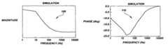
- FIGS. 1A and 1Bare, respectively, graphs of the magnitude and phase of eddy current effects of a simulated conductive distorter on a sensor
- FIGS. 2A and 2Bare, respectively, graphs of the magnitude and phase of eddy current effects of an actual conductive distorter on a sensor placed at three different positions (situations S 1 -S 3 );
- FIGS. 3A-3Care schematic diagrams illustrating, respectively, situations S 1 -S 3 of FIGS. 2A and 2B ;
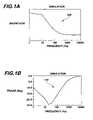
- FIGS. 4A and 4Bare, respectively, graphs of magnitude and phase of data presented in FIGS. 2A and 2B illustrating a method of the present invention for correcting inaccuracies caused by eddy current effects;
- FIG. 5is a flow chart of the method of FIGS. 4A , and 4 B;
- FIG. 6is a simplified schematic diagram illustrating components of a position and orientation determination system of the present invention.
- the induced sensor voltage due to a changing magnetic fieldis given by:
- v ⁇ ( t )- ⁇ ⁇ t ⁇ ⁇ S ⁇ B _ ⁇ ⁇ d S _ ⁇ 1 ⁇
- v(t)is the induced voltage
- Bis the magnetic flux density in the direction of S , the surface that encloses B (in all cases, the sensor surface area).
- Bis proportional to the current flowing in the field generator element.
- Electromagnetic tracking systems with multiple B-field generating elementscan time or frequency multiplex the B-field generators to distinguish the induced sensor signals generated by each generator. Time multiplexing is the only method that can presently be used with pulsed-DC electromagnetic tracking systems.
- the present inventorhas found that the frequency response of a sensor due to the field generator B-field and the B-field due to eddy currents can be represented in terms of lead, lag or lead-lag networks. This can be written succinctly in terms of a Laplace transform as:
- H sensor ⁇ ( s )k ⁇ ⁇ j ⁇ s + z j s + p j ⁇ 2 ⁇
- H sensor (s)is the transfer function relating the output of the sensor to the field excitation
- kis a gain constant
- z j and p jare, respectively, the zeros and poles of the network and are related to the characteristics of the conductive distorter and its position and orientation with respect to the sensor and field generator. This has been born out by experimental measurement and simulation.
- FIGS. 1A and 1Billustrate simulated frequency response data from a sensor of an AC-type tracking system, such as AC tracking system 600 of FIG. 6 , described in detail below.
- the conditionwas a conductive distorter located close behind the sensor, both of which were in front of, and away from, a field generator (this condition is similar to situation S 2 illustrated in FIG. 3B ).
- FIG. 1Ais a plot 100 of the simulated magnitude response
- FIG. 1Bis a plot 110 of the simulated phase response.
- FIGS. 2A and 2Bshow, respectively, a plot 200 of measured magnitude and a plot 210 of phase data from three different physical situations S 1 , S 2 , S 3 illustrated, respectively, in FIGS. 3A-3C .
- Situations S 1 , S 2 , S 3show a B-field source 310 and a magnetic sensor 320 in different positions relative to a conductive distorter 330 . Note that similarity between the data in plots 100 , 110 of FIGS. 1A and 1B and the data for Situation S 2 in plots 200 , 210 FIGS. 2A and 2B .
- Eddy current reductionis carried out by collecting sufficient data to determine the parameters k, p j and z j in Equation ⁇ 2 ⁇ , above.
- the undistorted field valueis taken as the resulting value of:
- the data collected by the sensorincludes the response of the sensor to a multiple frequency excitation.
- the datais then analyzed for magnitude and phase changes or, equivalently, for real and imaginary component changes.
- the determination of additional terms of Equation ⁇ 2 ⁇requires additional excitation frequencies.
- wis the frequency in radians.
- the measurements of the magnitude and phasecan be accomplished a number of ways well known in the art, such as coherent detection, discrete and fast Fourier transforms (DFT and FFT, respectively), sliding FFTs chirp Z transforms, Hartley and wavelet transforms, and analog and/or digital filters, among others.
- coherent detectiondiscrete and fast Fourier transforms (DFT and FFT, respectively)
- DFT and FFTdiscrete and fast Fourier transforms
- sliding FFTs chirp Z transformschirp Z transforms
- Hartley and wavelet transformsHartley and wavelet transforms
- analog and/or digital filtersamong others.
- the most commonly used methodis coherent detection.
- a sinusoidal (sin(wt)) excitation of the field generatormay be used.
- the amplitude of the sensed signalincreases linearly as a function of w. Therefore, the sensed signals must be normalized (i.e., the frequency effect removed) before using the signal to define a valid frequency response.
- the sensed signalmay be multiplied individually by cos(wt) and sin(wt) (also known as demodulation) and either integrated over an integer number of cycles or filtered, respectively, to obtain the real (R) (or in-phase) and imaginary (I) (or out-of-phase) components of the signal.
- H(w) and ⁇ (w)are known at two different frequencies w, they can be inserted into Equations ⁇ 4 a ⁇ and ⁇ 4 b ⁇ , which can then be solved for the parameters k, p and z.
- Sensors that are not based on the rate of change of the field(as in Equation ⁇ 5 ⁇ ) can also use this method. Such sensors do not require the frequency normalization noted above.
- the least-squares approachis generally: given m functions f 1 , f 2 , . . . , f m of the n variables x 1 ,x 2 , . . . , x n , with m ⁇ n, find values for x 1 ,x 2 , . . . , x n that solve the nonlinear least squares problem,
- the excitation frequenciesmust fall within a narrow band to be useful. For greatest sensitivity, the frequencies should range between 10 and 1,000 Hz, with pairs of frequencies being spaced at least 100 Hz apart. This frequency range is where the effects from the conductive distorter are most discernible. Others, such as Ashe in U.S. Pat. No. 6,172,499, have realized this. Two or more frequency excitations can also be accomplished by using harmonically rich excitation waveforms, as disclosed by the present inventor in U.S. Pat. No. 6,427,079, which is incorporated by reference herein.
- Electromagnetic tracking systemsuse either time division multiplexing, frequency division multiplexing or both to distinguish between fields generated by different transmitters. When time multiplexing is used there are always eddy current transients generated.
- transientsappear as other frequency and phase components in the frequency response and corrupt the measured real (R) and imaginary (I) components of the sensed signal.
- One method, used when time division multiplexing the transmitter excitationwaits a period of time after the transmitter excitation has started before measuring the real (R) and imaginary (I) components. This allows some portion of the transient to die away.
- demodulation with integrationa delay of an integer number of cycles is referred.
- demodulating and filteringa delay sufficient to allow most of the transient to settle out of the filter is preferred.
- the other preferred methodutilizes continuous transmitter excitation in a frequency division multiplexed manner.
- Continuous excitationeliminates the startup transient inherent in time-division multiplexing. While transients are generated as a conductive distorter is moved, they are of far less consequence when compared to excitation transients.
- the excitationscan be sets of two sinusoids or, as disclosed by the present inventor in U.S. Pat. No. 6,427,079, can be harmonically rich waveforms running continuously. Examples of suitable harmonically rich waveforms include square waves and triangular waves. It is generally only required that spectra from the various sensed waveforms do not overlap at the frequencies of interest.
- FIG. 5illustrates an adaptive distortion compensation method 500 of the present invention for setting j and number of excitation frequencies per transmitter.
- FIGS. 4A and 4Bshow, respectively, a magnitude plot 400 and a phase plot 410 of data presented in FIGS. 2A and 2B relative to situation S 3 that illustrate results of the application of distortion compensation method 500 .
- Method 500is described in more detail below.
- Equation ⁇ 10 ⁇how accurately the parameters k, z j and p j fit Equation ⁇ 2 ⁇ may be measured by the norm of the residuals.
- the norm of the residualsis defined as the square root of the sum of the squares of the modeling function minus the measured value, when evaluated at the determined parameters. This is illustrated in Equation ⁇ 10 ⁇ .
- Equation ⁇ 4 ⁇ and ⁇ 6 ⁇are used to represent the model and the measured values, respectively.
- a systemwill produce a small but finite norm in an environment that contains no magnetic distorters (i.e., highly-conductive materials). The value of this norm can be determined experimentally within a distorter-free environment and represents the THRESHOLD noted in steps 535 and 515 of method 500 .
- step 505magnetic field data from the field generators is sampled at the sense(s).
- step 510the data is processed to obtain the real (R) and imaginary (I) components of the sensed signal. This processing may be performed using any method for determining in-and-out-of-phase signal components known in the art, such as the techniques noted above.
- step 515the ratio of the imaginary to the real response for the second (higher) frequency I 2 /R 2 may be evaluated.
- the second frequencyis chosen here because it is more sensitive to conductive distorters.
- the parameters k, p and zmay calculated from Equation ⁇ 8 ⁇ and the norm calculated from Equation ⁇ 10 ⁇ . If, at step 535 , the norm is less than THRESHOLD the adjusted B-field may be calculated at step 540 using Equation ⁇ 3 ⁇ and supplied to the P&O algorithm at step 520 . The cycle is then started over at step 505 .
- the number of model parametersis increased at step 545 by incrementing j by one to increase the accuracy of the model.
- the adjusted B fieldmay be calculated in step 540 from Equation ⁇ 5 ⁇ and supplied to the P&O algorithm at step 520 . Otherwise, the next set of frequency data is incorporated to fit the model in step 530 and the process repeated until either the norm is less than THRESHOLD or the LIMIT relative to j is reached. It should be appreciated by those skilled in the art that the model order j does not have to be determined to completion at the end of each cycle. Rather, j could be adjusted up or down by one each cycle in an iterative manner.
- FIG. 6illustrates a system 600 of the present invention that may be used for determining the position and orientation of a remote object 604 relative to a coordinate reference frame (not shown).
- System 600may include one or more generators of electromagnetic fields, e.g., generators 608 A-H, a remote sensor 612 , a transmitter tablet 616 and a tracking processor 620 for processing transmitter and sensor signals.
- a mode of operation of system 600including appropriate techniques for determining position and orientation of sensor 612 relative to the reference coordinate frame of transmitter tablet 616 , is disclosed by the present inventor in U.S. Pat. No. 6,427,079, incorporated herein by reference above. However, other operating modes could be used in conjunction with the eddy current compensation method disclosed herein.
- Transmitter tablet 616includes a plurality of field generating elements, such as transmitter antennas 624 A-H.
- Antennas 624 A-Hneed only be spatially and rotationally distinct such that the field generated by each antenna be distinguishable at sensor 612 and that there is a unique set of field values at all positions within the measurement volume.
- Antennas 624 A-Hare typically eight magnetic loop windings of circular or rectangular geometry, but other geometries are possible.
- Antennas 624 A-Hare supplied with AC triangular waveforms of different frequencies by corresponding current drivers 630 A-H.
- the signalsare frequency division multiplexed so that the fields generated by each antenna 624 A-H are distinguishable from the fields generated by other antennas.
- This frequency division multiplexingmay be accomplished by a set of digital-to-analog converter (DACs) 634 A-H, each corresponding to a respective one of transmitter antennas 624 A-H.
- DACs 634 A-Hmay be driven by a digital signal processor (DSP) 638 within tracking processor 620 to generate the analog signals that are supplied as inputs to current drivers 630 A-H.
- DSPdigital signal processor
- eight current drivers 630 A-H, or power amplifying circuitsare provided, each being connected to a corresponding one of eight field generating antennas 624 A-H with eight DACs 634 A-H applying actuation signals simultaneously to each of the antennas through the eight individual driving circuits.
- Sensor 612is preferably, but not necessarily, a passive loop antenna that responds to the rate of change of magnetic field dB/dt.
- the output of sensor 612may be supplied to a differential preamplifier 642 .
- the output of preamplifier 642may be supplied to an anti-aliasing filter 646 having a frequency response chosen to prevent aliasing of the sampled data while allowing suitable sensed harmonic content of the frequency division multiplexed signals to pass unaffected to an analog-to-digital converter (ADC) 650 .
- ADCanalog-to-digital converter
- Sensor 612 , preamplifier 642 , anti-aliasing filter 646 and ADC 650may be considered to form a sensor circuit 652 .
- ADC 650converts the output of amplifier 642 to a discrete time digital representation for processing by DSP 638 .
- ADC 650converts analog data at a rate suitable for FFT processing and chosen such that the sampled signals spectra falls exactly within the FFTs frequency bins and contains no spectral leakage.
- the DSPadaptively picks which of the excitation waveforms harmonics to use.
- DSP 638provides the necessary timing signals for driving DACs 634 A-H and reading the data from ADC 650 .
- DSP 638also calculates the position and orientation of sensor 612 in a reference coordinate frame defined by transmitter tablet 616 and may supply the results to other systems via interface 654 .
- the frequency multiplexed AC excitation frequenciesare used.
- time multiplexed, and time and frequency multiplexed waveformscould also be used with this technique.
- system 600may utilize method 500 of FIG. 5 to remove, or at least lessen, the effects of eddy currents within conductive distorters, e.g., conductive distorters 658 A-C shown in FIG. 6 .
- datamay be collected by DSP 638 at step 505 via sensor circuit 652 .
- the number of data pointis dependent on the rate of data conversion of ADC 650 as well as its suitability for signal processing. The rate is chosen such that the sampled signals spectra contains no spectral leakage.
- DSP 638collects all the data points from ADC 650 , processes the data at step 510 and utilizes the in-and-out-of-phase frequency components to perform the modeling of the data in step 530 .
- DSP 638may also perform the steps of determining the number of networks needed to achieve a desirable result, i.e., steps 515 , 525 , 535 , 545 and 550 , as well as step 540 of calculating the adjusted B field and step 520 of calculating the position and orientation of sensor 612 using the lead-lag network methods discussed above.
- System 600may further include one or more memories 662 , e.g., RAM, ROM, magnetic, optical, etc., that contain the computer instructions 664 necessary for DSP 638 to perform its various functions, such as the functions necessary to perform all or part of method 500 and all or part of the lead-lag network modeling described above.
- memories 662e.g., RAM, ROM, magnetic, optical, etc.
- system 600could be reversed, i.e., a driver excitation could be output to a single transmitter antenna and multiple sensor antennas could simultaneously measure the field. Also, since all real measurement systems have a finite bandwidth, the system will have its own intrinsic low-pass filter response that can be characterized in terms of the z j and p j parameters. These could be measured at the time of manufacture and stored for use during normal system operation.
- Multiple sensors 612can be used for forming three-dimensional echocardiograms by tracking a handheld ultrasound scanner head.
- multiple sensors 612can be associated with a particular body part for the purpose of conducting biomechanical studies.
- Still another applicationinvolves the monitoring of the body movements of an invalid for the purpose of creating a nonverbal communication system or providing a technique for remotely controlling various devices with nonverbal communicative body motion.
- Another applicationis the tracking of head movements for use in virtual reality headsets.
- Still another applicationis a three-dimensional (3-D) mouse for navigating in multidimensional databases or as a tool for use with VRML, a 3-D file format popular on the Internet.
Landscapes
- Health & Medical Sciences (AREA)
- Surgery (AREA)
- Life Sciences & Earth Sciences (AREA)
- Engineering & Computer Science (AREA)
- Medical Informatics (AREA)
- Biomedical Technology (AREA)
- Heart & Thoracic Surgery (AREA)
- Nuclear Medicine, Radiotherapy & Molecular Imaging (AREA)
- Molecular Biology (AREA)
- Animal Behavior & Ethology (AREA)
- General Health & Medical Sciences (AREA)
- Public Health (AREA)
- Veterinary Medicine (AREA)
- Robotics (AREA)
- Oral & Maxillofacial Surgery (AREA)
- Pathology (AREA)
- Measurement Of Length, Angles, Or The Like Using Electric Or Magnetic Means (AREA)
Abstract
Description
where v(t) is the induced voltage and
where Hsensor(s) is the transfer function relating the output of the sensor to the field excitation; k is a gain constant; and zjand pjare, respectively, the zeros and poles of the network and are related to the characteristics of the conductive distorter and its position and orientation with respect to the sensor and field generator. This has been born out by experimental measurement and simulation.
since this is the value of the network at zero Hertz, i.e., where conductive distortion no longer exists. The data collected by the sensor includes the response of the sensor to a multiple frequency excitation. The data is then analyzed for magnitude and phase changes or, equivalently, for real and imaginary component changes. The minimum number of frequencies is two, which provides tow magnitudes and two phases (providing four equations) for determining three unknown parameters (for j=1). The determination of additional terms of Equation {2} requires additional excitation frequencies.
Θ(w)=tan−1(w/z)−tan−1(w/p) {4b}
v=f(position,orientation)(−wcos(wt)) {5}
where v is the sensed voltage induced across the sensor, f is a gain related to the position and orientation of the sensor with respect to the transmitter and the −wcos(wt) term is due to Equation {1}. The amplitude of the sensed signal increases linearly as a function of w. Therefore, the sensed signals must be normalized (i.e., the frequency effect removed) before using the signal to define a valid frequency response. The sensed signal may be multiplied individually by cos(wt) and sin(wt) (also known as demodulation) and either integrated over an integer number of cycles or filtered, respectively, to obtain the real (R) (or in-phase) and imaginary (I) (or out-of-phase) components of the signal. The magnitude and phase can then be determined by:
H(w)=√{square root over ((R2+I2))} {6a}
Θ(w)=tan−1(I/R) {6b}
Once H(w) and Θ(w) are known at two different frequencies w, they can be inserted into Equations {4a} and {4b}, which can then be solved for the parameters k, p and z. Sensors that are not based on the rate of change of the field (as in Equation {5}) can also use this method. Such sensors do not require the frequency normalization noted above.
Many well-known methods exist to help solve such problems. The predominant methods require the evaluation of the Jacobian (i.e., a matrix of partial derivatives of the equations with respect to the unknowns), either explicitly or by finite differences and sometimes requiring the evaluation of the Hessian (i.e., a matrix of second partial derivatives of the equations with respect to the unknowns). These methods are often referred to as Netwon methods, gradient methods or steepest-descent methods, or variations on this theme. Numerical Recipes in Fortran, 2ndEdition, by Press et al., Cambridge University Press 1992, and User Guide for MINPACK-1, Argonne National Laboratory, 1980, provide details on these methods.
where w1and w2represent two excitation frequencies, respectively; R1represents the real component at w1; and I1and I2represent the imaginary components at w1and w2, respectively. Note that the second real component (R2) is not used. Other sets of equations can be derived using other combinations of components, as well as averaging the resulting parameters determined from various combinations, as would be known in the art. Additional and more complicated closed-form solutions result when j≧2.
hsensor(t)=k(δ)(t)+(z−p)e−pt) {9}
where hsensor(t) is the impulse response; t is time, δ(t) is the unit impulse, k is a gain contant, z and p are, respectively, the zero and pole of the network and are related to the characteristics of the conductive distorter and its position and orientation with respect to the sensor(s) and field generator(s) and e is the exponential function. Convolving Equation {9} with the time domain representation of the generator excitation yields the sensed sensor signal affected by a conductive distorter. Another way to interpret this is to note that convolving a waveform with the unit impulse yields the waveform, convolving a waveform with the function (z−p)e−ptyields an amplitude-modified, phase-shifted waveform plus exponentially decaying transient terms. It is these same transients that pulsed-DC electromagnetic tracking systems combat by watching and evaluating their decay (see, e.g., U.S. Pat. Nos. 4,849,692 and 4,945,305 to Blood).
Here, Equations {4} and {6} are used to represent the model and the measured values, respectively. In practice, a system will produce a small but finite norm in an environment that contains no magnetic distorters (i.e., highly-conductive materials). The value of this norm can be determined experimentally within a distorter-free environment and represents the THRESHOLD noted in
Claims (19)
Priority Applications (2)
| Application Number | Priority Date | Filing Date | Title |
|---|---|---|---|
| US10/945,277US7373271B1 (en) | 2004-09-20 | 2004-09-20 | System and method for measuring position and orientation using distortion-compensated magnetic fields |
| US12/037,249US7788060B2 (en) | 2004-09-20 | 2008-02-26 | System and method for measuring position and orientation using distortion-compensated magnetic fields |
Applications Claiming Priority (1)
| Application Number | Priority Date | Filing Date | Title |
|---|---|---|---|
| US10/945,277US7373271B1 (en) | 2004-09-20 | 2004-09-20 | System and method for measuring position and orientation using distortion-compensated magnetic fields |
Related Child Applications (1)
| Application Number | Title | Priority Date | Filing Date |
|---|---|---|---|
| US12/037,249DivisionUS7788060B2 (en) | 2004-09-20 | 2008-02-26 | System and method for measuring position and orientation using distortion-compensated magnetic fields |
Publications (1)
| Publication Number | Publication Date |
|---|---|
| US7373271B1true US7373271B1 (en) | 2008-05-13 |
Family
ID=39361697
Family Applications (2)
| Application Number | Title | Priority Date | Filing Date |
|---|---|---|---|
| US10/945,277Active2026-02-10US7373271B1 (en) | 2004-09-20 | 2004-09-20 | System and method for measuring position and orientation using distortion-compensated magnetic fields |
| US12/037,249Expired - LifetimeUS7788060B2 (en) | 2004-09-20 | 2008-02-26 | System and method for measuring position and orientation using distortion-compensated magnetic fields |
Family Applications After (1)
| Application Number | Title | Priority Date | Filing Date |
|---|---|---|---|
| US12/037,249Expired - LifetimeUS7788060B2 (en) | 2004-09-20 | 2008-02-26 | System and method for measuring position and orientation using distortion-compensated magnetic fields |
Country Status (1)
| Country | Link |
|---|---|
| US (2) | US7373271B1 (en) |
Cited By (80)
| Publication number | Priority date | Publication date | Assignee | Title |
|---|---|---|---|---|
| US20080118135A1 (en)* | 2006-11-10 | 2008-05-22 | Superdimension, Ltd. | Adaptive Navigation Technique For Navigating A Catheter Through A Body Channel Or Cavity |
| US20080167639A1 (en)* | 2007-01-08 | 2008-07-10 | Superdimension Ltd. | Methods for localized intra-body treatment of tissue |
| US20080262297A1 (en)* | 2004-04-26 | 2008-10-23 | Super Dimension Ltd. | System and Method for Image-Based Alignment of an Endoscope |
| US20090156951A1 (en)* | 2007-07-09 | 2009-06-18 | Superdimension, Ltd. | Patient breathing modeling |
| US20100008555A1 (en)* | 2008-05-15 | 2010-01-14 | Superdimension, Ltd. | Automatic Pathway And Waypoint Generation And Navigation Method |
| US20100034449A1 (en)* | 2008-06-06 | 2010-02-11 | Superdimension, Ltd. | Hybrid Registration Method |
| US20100127696A1 (en)* | 2008-11-26 | 2010-05-27 | General Electric Company | Magnetoresistance sensors for position and orientation determination |
| US20100137705A1 (en)* | 2008-11-28 | 2010-06-03 | General Electric Company | Surgical Navigation System with Magnetoresistance Sensors |
| US20100138183A1 (en)* | 2008-11-29 | 2010-06-03 | General Electric Company | Surgical Navigation Enabled Imaging Table Environment |
| US20100198015A1 (en)* | 2003-09-15 | 2010-08-05 | Benny Greenburg | System Of Accessories For Use With Bronchoscopes |
| US20100222711A1 (en)* | 2009-02-25 | 2010-09-02 | Sherlock NMD, LLC, a Nevada Corporation | Devices, systems and methods for capturing biomechanical motion |
| US20100249571A1 (en)* | 2009-03-31 | 2010-09-30 | General Electric Company | Surgical navigation system with wireless magnetoresistance tracking sensors |
| US20100305427A1 (en)* | 2009-06-01 | 2010-12-02 | General Electric Company | Long-range planar sensor array for use in a surgical navigation system |
| US20110151587A1 (en)* | 2009-12-21 | 2011-06-23 | General Electric Company | Method of producing an integrated micromagnet sensor assembly |
| US7998062B2 (en) | 2004-03-29 | 2011-08-16 | Superdimension, Ltd. | Endoscope structures and techniques for navigating to a target in branched structure |
| US8388546B2 (en) | 2006-10-23 | 2013-03-05 | Bard Access Systems, Inc. | Method of locating the tip of a central venous catheter |
| US8388541B2 (en) | 2007-11-26 | 2013-03-05 | C. R. Bard, Inc. | Integrated system for intravascular placement of a catheter |
| US8428328B2 (en) | 2010-02-01 | 2013-04-23 | Superdimension, Ltd | Region-growing algorithm |
| US8437833B2 (en) | 2008-10-07 | 2013-05-07 | Bard Access Systems, Inc. | Percutaneous magnetic gastrostomy |
| US8473032B2 (en) | 2008-06-03 | 2013-06-25 | Superdimension, Ltd. | Feature-based registration method |
| US8478382B2 (en) | 2008-02-11 | 2013-07-02 | C. R. Bard, Inc. | Systems and methods for positioning a catheter |
| US8512256B2 (en) | 2006-10-23 | 2013-08-20 | Bard Access Systems, Inc. | Method of locating the tip of a central venous catheter |
| US8611984B2 (en) | 2009-04-08 | 2013-12-17 | Covidien Lp | Locatable catheter |
| US20140002063A1 (en)* | 2012-06-27 | 2014-01-02 | Ascension Technology Corporation | System and method for magnetic position tracking |
| USD699359S1 (en) | 2011-08-09 | 2014-02-11 | C. R. Bard, Inc. | Ultrasound probe head |
| US8764725B2 (en) | 2004-02-09 | 2014-07-01 | Covidien Lp | Directional anchoring mechanism, method and applications thereof |
| US8781555B2 (en) | 2007-11-26 | 2014-07-15 | C. R. Bard, Inc. | System for placement of a catheter including a signal-generating stylet |
| US8784336B2 (en) | 2005-08-24 | 2014-07-22 | C. R. Bard, Inc. | Stylet apparatuses and methods of manufacture |
| US8801693B2 (en) | 2010-10-29 | 2014-08-12 | C. R. Bard, Inc. | Bioimpedance-assisted placement of a medical device |
| US8849382B2 (en) | 2007-11-26 | 2014-09-30 | C. R. Bard, Inc. | Apparatus and display methods relating to intravascular placement of a catheter |
| US8905920B2 (en) | 2007-09-27 | 2014-12-09 | Covidien Lp | Bronchoscope adapter and method |
| US8932207B2 (en) | 2008-07-10 | 2015-01-13 | Covidien Lp | Integrated multi-functional endoscopic tool |
| USD724745S1 (en) | 2011-08-09 | 2015-03-17 | C. R. Bard, Inc. | Cap for an ultrasound probe |
| US9125578B2 (en) | 2009-06-12 | 2015-09-08 | Bard Access Systems, Inc. | Apparatus and method for catheter navigation and tip location |
| US9211107B2 (en) | 2011-11-07 | 2015-12-15 | C. R. Bard, Inc. | Ruggedized ultrasound hydrogel insert |
| US9257220B2 (en) | 2013-03-05 | 2016-02-09 | Ezono Ag | Magnetization device and method |
| US9339206B2 (en) | 2009-06-12 | 2016-05-17 | Bard Access Systems, Inc. | Adaptor for endovascular electrocardiography |
| CN105658169A (en)* | 2013-08-30 | 2016-06-08 | 菲亚戈股份有限公司 | Method and device for navigating active surgical instruments |
| US9445734B2 (en) | 2009-06-12 | 2016-09-20 | Bard Access Systems, Inc. | Devices and methods for endovascular electrography |
| US9459087B2 (en) | 2013-03-05 | 2016-10-04 | Ezono Ag | Magnetic position detection system |
| US9456766B2 (en) | 2007-11-26 | 2016-10-04 | C. R. Bard, Inc. | Apparatus for use with needle insertion guidance system |
| US9492097B2 (en) | 2007-11-26 | 2016-11-15 | C. R. Bard, Inc. | Needle length determination and calibration for insertion guidance system |
| US9521961B2 (en) | 2007-11-26 | 2016-12-20 | C. R. Bard, Inc. | Systems and methods for guiding a medical instrument |
| US9532724B2 (en) | 2009-06-12 | 2017-01-03 | Bard Access Systems, Inc. | Apparatus and method for catheter navigation using endovascular energy mapping |
| US9554716B2 (en) | 2007-11-26 | 2017-01-31 | C. R. Bard, Inc. | Insertion guidance system for needles and medical components |
| US9575140B2 (en) | 2008-04-03 | 2017-02-21 | Covidien Lp | Magnetic interference detection system and method |
| US9597008B2 (en) | 2011-09-06 | 2017-03-21 | Ezono Ag | Imaging probe and method of obtaining position and/or orientation information |
| US9636031B2 (en) | 2007-11-26 | 2017-05-02 | C.R. Bard, Inc. | Stylets for use with apparatus for intravascular placement of a catheter |
| US9649048B2 (en) | 2007-11-26 | 2017-05-16 | C. R. Bard, Inc. | Systems and methods for breaching a sterile field for intravascular placement of a catheter |
| US9839372B2 (en) | 2014-02-06 | 2017-12-12 | C. R. Bard, Inc. | Systems and methods for guidance and placement of an intravascular device |
| US9901714B2 (en) | 2008-08-22 | 2018-02-27 | C. R. Bard, Inc. | Catheter assembly including ECG sensor and magnetic assemblies |
| US10046139B2 (en) | 2010-08-20 | 2018-08-14 | C. R. Bard, Inc. | Reconfirmation of ECG-assisted catheter tip placement |
| US10101179B2 (en) | 2015-07-20 | 2018-10-16 | Commissariat à l'Energie Atomique et aux Energies Alternatives | Electromagnetic position tracking system |
| US10285760B2 (en) | 2015-02-04 | 2019-05-14 | Queen's University At Kingston | Methods and apparatus for improved electromagnetic tracking and localization |
| US10349890B2 (en) | 2015-06-26 | 2019-07-16 | C. R. Bard, Inc. | Connector interface for ECG-based catheter positioning system |
| US10418705B2 (en) | 2016-10-28 | 2019-09-17 | Covidien Lp | Electromagnetic navigation antenna assembly and electromagnetic navigation system including the same |
| US10426555B2 (en) | 2015-06-03 | 2019-10-01 | Covidien Lp | Medical instrument with sensor for use in a system and method for electromagnetic navigation |
| US10434278B2 (en) | 2013-03-05 | 2019-10-08 | Ezono Ag | System for image guided procedure |
| US10446931B2 (en) | 2016-10-28 | 2019-10-15 | Covidien Lp | Electromagnetic navigation antenna assembly and electromagnetic navigation system including the same |
| US10449330B2 (en) | 2007-11-26 | 2019-10-22 | C. R. Bard, Inc. | Magnetic element-equipped needle assemblies |
| US10478254B2 (en) | 2016-05-16 | 2019-11-19 | Covidien Lp | System and method to access lung tissue |
| US10517505B2 (en) | 2016-10-28 | 2019-12-31 | Covidien Lp | Systems, methods, and computer-readable media for optimizing an electromagnetic navigation system |
| US20200007173A1 (en)* | 2018-07-02 | 2020-01-02 | Boston Scientific Scimed Inc. | Magnetic tracking transmitter |
| US10524691B2 (en) | 2007-11-26 | 2020-01-07 | C. R. Bard, Inc. | Needle assembly including an aligned magnetic element |
| US10582834B2 (en) | 2010-06-15 | 2020-03-10 | Covidien Lp | Locatable expandable working channel and method |
| US10615500B2 (en) | 2016-10-28 | 2020-04-07 | Covidien Lp | System and method for designing electromagnetic navigation antenna assemblies |
| US10639008B2 (en) | 2009-10-08 | 2020-05-05 | C. R. Bard, Inc. | Support and cover structures for an ultrasound probe head |
| US10638952B2 (en) | 2016-10-28 | 2020-05-05 | Covidien Lp | Methods, systems, and computer-readable media for calibrating an electromagnetic navigation system |
| US10722311B2 (en) | 2016-10-28 | 2020-07-28 | Covidien Lp | System and method for identifying a location and/or an orientation of an electromagnetic sensor based on a map |
| US10751126B2 (en) | 2016-10-28 | 2020-08-25 | Covidien Lp | System and method for generating a map for electromagnetic navigation |
| US10751509B2 (en) | 2007-11-26 | 2020-08-25 | C. R. Bard, Inc. | Iconic representations for guidance of an indwelling medical device |
| US10792106B2 (en) | 2016-10-28 | 2020-10-06 | Covidien Lp | System for calibrating an electromagnetic navigation system |
| US10820885B2 (en) | 2012-06-15 | 2020-11-03 | C. R. Bard, Inc. | Apparatus and methods for detection of a removable cap on an ultrasound probe |
| US10952593B2 (en) | 2014-06-10 | 2021-03-23 | Covidien Lp | Bronchoscope adapter |
| US10973584B2 (en) | 2015-01-19 | 2021-04-13 | Bard Access Systems, Inc. | Device and method for vascular access |
| US10992079B2 (en) | 2018-10-16 | 2021-04-27 | Bard Access Systems, Inc. | Safety-equipped connection systems and methods thereof for establishing electrical connections |
| US11000207B2 (en) | 2016-01-29 | 2021-05-11 | C. R. Bard, Inc. | Multiple coil system for tracking a medical device |
| US11103213B2 (en) | 2009-10-08 | 2021-08-31 | C. R. Bard, Inc. | Spacers for use with an ultrasound probe |
| US11219489B2 (en) | 2017-10-31 | 2022-01-11 | Covidien Lp | Devices and systems for providing sensors in parallel with medical tools |
| US12011233B2 (en) | 2019-11-26 | 2024-06-18 | Arizona Board Of Regents On Behalf Of Arizona State University | System and method for determining position of a steerable assembly within tissue of an animal body |
Families Citing this family (32)
| Publication number | Priority date | Publication date | Assignee | Title |
|---|---|---|---|---|
| US7559931B2 (en) | 2003-06-09 | 2009-07-14 | OrthAlign, Inc. | Surgical orientation system and method |
| US20100153081A1 (en)* | 2008-12-11 | 2010-06-17 | Mako Surgical Corp. | Implant planning for multiple implant components using constraints |
| EP2136715B1 (en)* | 2007-04-19 | 2014-06-25 | Mako Surgical Corp. | Implant planning using captured joint motion information |
| CA2706356C (en) | 2008-02-20 | 2017-03-28 | Mako Surgical Corp. | Implant planning using corrected captured joint motion information |
| AU2009273863B2 (en) | 2008-07-24 | 2014-12-18 | OrthAlign, Inc. | Systems and methods for joint replacement |
| AU2009291743B2 (en) | 2008-09-10 | 2015-02-05 | Orthalign, Inc | Hip surgery systems and methods |
| US8118815B2 (en) | 2009-07-24 | 2012-02-21 | OrthAlign, Inc. | Systems and methods for joint replacement |
| US10869771B2 (en) | 2009-07-24 | 2020-12-22 | OrthAlign, Inc. | Systems and methods for joint replacement |
| AU2011341678B2 (en)* | 2010-01-21 | 2014-12-11 | OrthAlign, Inc. | Systems and methods for joint replacement |
| US9891291B2 (en) | 2011-08-01 | 2018-02-13 | Soreq Nuclear Research Center | Magnetic tracking system |
| US9549742B2 (en) | 2012-05-18 | 2017-01-24 | OrthAlign, Inc. | Devices and methods for knee arthroplasty |
| US9649160B2 (en) | 2012-08-14 | 2017-05-16 | OrthAlign, Inc. | Hip replacement navigation system and method |
| DE102013214067A1 (en) | 2013-07-17 | 2015-01-22 | Fiagon Gmbh | Device and method for connecting a medical instrument to a position detection system |
| DE102013222230A1 (en) | 2013-10-31 | 2015-04-30 | Fiagon Gmbh | Surgical instrument |
| US9754367B2 (en) | 2014-07-02 | 2017-09-05 | Covidien Lp | Trachea marking |
| US9603668B2 (en) | 2014-07-02 | 2017-03-28 | Covidien Lp | Dynamic 3D lung map view for tool navigation inside the lung |
| CN106232010B (en) | 2014-07-02 | 2020-03-31 | 柯惠有限合伙公司 | System and method for detecting trachea |
| US9770216B2 (en) | 2014-07-02 | 2017-09-26 | Covidien Lp | System and method for navigating within the lung |
| CN106659453B (en) | 2014-07-02 | 2020-05-26 | 柯惠有限合伙公司 | System and method for segmenting lungs |
| AU2015283946B2 (en) | 2014-07-02 | 2019-09-12 | Covidien Lp | Real-time automatic registration feedback |
| US20160000414A1 (en) | 2014-07-02 | 2016-01-07 | Covidien Lp | Methods for marking biopsy location |
| US10363149B2 (en) | 2015-02-20 | 2019-07-30 | OrthAlign, Inc. | Hip replacement navigation system and method |
| US10986990B2 (en) | 2015-09-24 | 2021-04-27 | Covidien Lp | Marker placement |
| US10709352B2 (en) | 2015-10-27 | 2020-07-14 | Covidien Lp | Method of using lung airway carina locations to improve ENB registration |
| CA3056495A1 (en) | 2017-03-14 | 2018-09-20 | OrthAlign, Inc. | Soft tissue measurement & balancing systems and methods |
| EP3595554A4 (en) | 2017-03-14 | 2021-01-06 | OrthAlign, Inc. | Hip replacement navigation systems and methods |
| US11224392B2 (en) | 2018-02-01 | 2022-01-18 | Covidien Lp | Mapping disease spread |
| CA3031276A1 (en) | 2018-02-08 | 2019-08-08 | Ascension Technology Corporation | Compensating for distortion in an electromagnetic tracking system |
| EP3719749A1 (en) | 2019-04-03 | 2020-10-07 | Fiagon AG Medical Technologies | Registration method and setup |
| US12089902B2 (en) | 2019-07-30 | 2024-09-17 | Coviden Lp | Cone beam and 3D fluoroscope lung navigation |
| US11976921B2 (en)* | 2021-09-16 | 2024-05-07 | Penumbra, Inc. | Method and apparatus for reducing magnetic tracking error due to floor distortion |
| US12310676B2 (en)* | 2022-11-22 | 2025-05-27 | Medtronic Navigation, Inc. | Navigation at ultra low to high frequencies |
Citations (18)
| Publication number | Priority date | Publication date | Assignee | Title |
|---|---|---|---|---|
| US3868565A (en) | 1973-07-30 | 1975-02-25 | Jack Kuipers | Object tracking and orientation determination means, system and process |
| US4054881A (en) | 1976-04-26 | 1977-10-18 | The Austin Company | Remote object position locater |
| US4622644A (en) | 1984-05-10 | 1986-11-11 | Position Orientation Systems, Ltd. | Magnetic position and orientation measurement system |
| US4710708A (en) | 1981-04-27 | 1987-12-01 | Develco | Method and apparatus employing received independent magnetic field components of a transmitted alternating magnetic field for determining location |
| US4737794A (en) | 1985-12-09 | 1988-04-12 | Mcdonnell Douglas Corporation | Method and apparatus for determining remote object orientation and position |
| US4829250A (en) | 1988-02-10 | 1989-05-09 | Honeywell, Inc. | Magnetic direction finding device with improved accuracy |
| US4945305A (en) | 1986-10-09 | 1990-07-31 | Ascension Technology Corporation | Device for quantitatively measuring the relative position and orientation of two bodies in the presence of metals utilizing direct current magnetic fields |
| WO1994004938A1 (en) | 1992-08-14 | 1994-03-03 | British Telecommunications Public Limited Company | Position location system |
| US5347289A (en) | 1993-06-29 | 1994-09-13 | Honeywell, Inc. | Method and device for measuring the position and orientation of objects in the presence of interfering metals |
| US5377678A (en) | 1991-09-03 | 1995-01-03 | General Electric Company | Tracking system to follow the position and orientation of a device with radiofrequency fields |
| US5453686A (en) | 1993-04-08 | 1995-09-26 | Polhemus Incorporated | Pulsed-DC position and orientation measurement system |
| WO1996005768A1 (en) | 1994-08-19 | 1996-02-29 | Biosense, Inc. | Medical diagnosis, treatment and imaging systems |
| US5592939A (en) | 1995-06-14 | 1997-01-14 | Martinelli; Michael A. | Method and system for navigating a catheter probe |
| US5600330A (en) | 1994-07-12 | 1997-02-04 | Ascension Technology Corporation | Device for measuring position and orientation using non-dipole magnet IC fields |
| US6147480A (en) | 1997-10-23 | 2000-11-14 | Biosense, Inc. | Detection of metal disturbance |
| US6172499B1 (en) | 1999-10-29 | 2001-01-09 | Ascension Technology Corporation | Eddy current error-reduced AC magnetic position measurement system |
| US6427079B1 (en)* | 1999-08-09 | 2002-07-30 | Cormedica Corporation | Position and orientation measuring with magnetic fields |
| US6528989B1 (en) | 2000-03-21 | 2003-03-04 | Skysense, Ltd. | AC magnetic tracker for operation close to metallic objects |
Family Cites Families (1)
| Publication number | Priority date | Publication date | Assignee | Title |
|---|---|---|---|---|
| US7340265B2 (en)* | 2002-02-28 | 2008-03-04 | Atheros Communications, Inc. | Method and apparatus for transient frequency distortion compensation |
- 2004
- 2004-09-20USUS10/945,277patent/US7373271B1/enactiveActive
- 2008
- 2008-02-26USUS12/037,249patent/US7788060B2/ennot_activeExpired - Lifetime
Patent Citations (18)
| Publication number | Priority date | Publication date | Assignee | Title |
|---|---|---|---|---|
| US3868565A (en) | 1973-07-30 | 1975-02-25 | Jack Kuipers | Object tracking and orientation determination means, system and process |
| US4054881A (en) | 1976-04-26 | 1977-10-18 | The Austin Company | Remote object position locater |
| US4710708A (en) | 1981-04-27 | 1987-12-01 | Develco | Method and apparatus employing received independent magnetic field components of a transmitted alternating magnetic field for determining location |
| US4622644A (en) | 1984-05-10 | 1986-11-11 | Position Orientation Systems, Ltd. | Magnetic position and orientation measurement system |
| US4737794A (en) | 1985-12-09 | 1988-04-12 | Mcdonnell Douglas Corporation | Method and apparatus for determining remote object orientation and position |
| US4945305A (en) | 1986-10-09 | 1990-07-31 | Ascension Technology Corporation | Device for quantitatively measuring the relative position and orientation of two bodies in the presence of metals utilizing direct current magnetic fields |
| US4829250A (en) | 1988-02-10 | 1989-05-09 | Honeywell, Inc. | Magnetic direction finding device with improved accuracy |
| US5377678A (en) | 1991-09-03 | 1995-01-03 | General Electric Company | Tracking system to follow the position and orientation of a device with radiofrequency fields |
| WO1994004938A1 (en) | 1992-08-14 | 1994-03-03 | British Telecommunications Public Limited Company | Position location system |
| US5453686A (en) | 1993-04-08 | 1995-09-26 | Polhemus Incorporated | Pulsed-DC position and orientation measurement system |
| US5347289A (en) | 1993-06-29 | 1994-09-13 | Honeywell, Inc. | Method and device for measuring the position and orientation of objects in the presence of interfering metals |
| US5600330A (en) | 1994-07-12 | 1997-02-04 | Ascension Technology Corporation | Device for measuring position and orientation using non-dipole magnet IC fields |
| WO1996005768A1 (en) | 1994-08-19 | 1996-02-29 | Biosense, Inc. | Medical diagnosis, treatment and imaging systems |
| US5592939A (en) | 1995-06-14 | 1997-01-14 | Martinelli; Michael A. | Method and system for navigating a catheter probe |
| US6147480A (en) | 1997-10-23 | 2000-11-14 | Biosense, Inc. | Detection of metal disturbance |
| US6427079B1 (en)* | 1999-08-09 | 2002-07-30 | Cormedica Corporation | Position and orientation measuring with magnetic fields |
| US6172499B1 (en) | 1999-10-29 | 2001-01-09 | Ascension Technology Corporation | Eddy current error-reduced AC magnetic position measurement system |
| US6528989B1 (en) | 2000-03-21 | 2003-03-04 | Skysense, Ltd. | AC magnetic tracker for operation close to metallic objects |
Cited By (183)
| Publication number | Priority date | Publication date | Assignee | Title |
|---|---|---|---|---|
| US9642514B2 (en) | 2002-04-17 | 2017-05-09 | Covidien Lp | Endoscope structures and techniques for navigating to a target in a branched structure |
| US8696548B2 (en) | 2002-04-17 | 2014-04-15 | Covidien Lp | Endoscope structures and techniques for navigating to a target in branched structure |
| US8696685B2 (en) | 2002-04-17 | 2014-04-15 | Covidien Lp | Endoscope structures and techniques for navigating to a target in branched structure |
| US10743748B2 (en) | 2002-04-17 | 2020-08-18 | Covidien Lp | Endoscope structures and techniques for navigating to a target in branched structure |
| US9089261B2 (en) | 2003-09-15 | 2015-07-28 | Covidien Lp | System of accessories for use with bronchoscopes |
| US8663088B2 (en) | 2003-09-15 | 2014-03-04 | Covidien Lp | System of accessories for use with bronchoscopes |
| US20100198015A1 (en)* | 2003-09-15 | 2010-08-05 | Benny Greenburg | System Of Accessories For Use With Bronchoscopes |
| US10383509B2 (en) | 2003-09-15 | 2019-08-20 | Covidien Lp | System of accessories for use with bronchoscopes |
| US8764725B2 (en) | 2004-02-09 | 2014-07-01 | Covidien Lp | Directional anchoring mechanism, method and applications thereof |
| US10173043B2 (en) | 2004-02-09 | 2019-01-08 | Covidien Lp | Directional anchoring mechanism, and method and applications thereof |
| US10406325B2 (en) | 2004-02-09 | 2019-09-10 | Covidien Lp | Directional anchoring mechanism, method and applications thereof |
| US7998062B2 (en) | 2004-03-29 | 2011-08-16 | Superdimension, Ltd. | Endoscope structures and techniques for navigating to a target in branched structure |
| US20080262297A1 (en)* | 2004-04-26 | 2008-10-23 | Super Dimension Ltd. | System and Method for Image-Based Alignment of an Endoscope |
| US9055881B2 (en) | 2004-04-26 | 2015-06-16 | Super Dimension Ltd. | System and method for image-based alignment of an endoscope |
| US10321803B2 (en) | 2004-04-26 | 2019-06-18 | Covidien Lp | System and method for image-based alignment of an endoscope |
| US11207496B2 (en) | 2005-08-24 | 2021-12-28 | C. R. Bard, Inc. | Stylet apparatuses and methods of manufacture |
| US8784336B2 (en) | 2005-08-24 | 2014-07-22 | C. R. Bard, Inc. | Stylet apparatuses and methods of manufacture |
| US10004875B2 (en) | 2005-08-24 | 2018-06-26 | C. R. Bard, Inc. | Stylet apparatuses and methods of manufacture |
| US9833169B2 (en) | 2006-10-23 | 2017-12-05 | Bard Access Systems, Inc. | Method of locating the tip of a central venous catheter |
| US8388546B2 (en) | 2006-10-23 | 2013-03-05 | Bard Access Systems, Inc. | Method of locating the tip of a central venous catheter |
| US8774907B2 (en) | 2006-10-23 | 2014-07-08 | Bard Access Systems, Inc. | Method of locating the tip of a central venous catheter |
| US9345422B2 (en) | 2006-10-23 | 2016-05-24 | Bard Acess Systems, Inc. | Method of locating the tip of a central venous catheter |
| US8858455B2 (en) | 2006-10-23 | 2014-10-14 | Bard Access Systems, Inc. | Method of locating the tip of a central venous catheter |
| US9265443B2 (en) | 2006-10-23 | 2016-02-23 | Bard Access Systems, Inc. | Method of locating the tip of a central venous catheter |
| US8512256B2 (en) | 2006-10-23 | 2013-08-20 | Bard Access Systems, Inc. | Method of locating the tip of a central venous catheter |
| US9129359B2 (en) | 2006-11-10 | 2015-09-08 | Covidien Lp | Adaptive navigation technique for navigating a catheter through a body channel or cavity |
| US20080118135A1 (en)* | 2006-11-10 | 2008-05-22 | Superdimension, Ltd. | Adaptive Navigation Technique For Navigating A Catheter Through A Body Channel Or Cavity |
| US10346976B2 (en) | 2006-11-10 | 2019-07-09 | Covidien Lp | Adaptive navigation technique for navigating a catheter through a body channel or cavity |
| US11631174B2 (en) | 2006-11-10 | 2023-04-18 | Covidien Lp | Adaptive navigation technique for navigating a catheter through a body channel or cavity |
| US11024026B2 (en) | 2006-11-10 | 2021-06-01 | Covidien Lp | Adaptive navigation technique for navigating a catheter through a body channel or cavity |
| US20080167639A1 (en)* | 2007-01-08 | 2008-07-10 | Superdimension Ltd. | Methods for localized intra-body treatment of tissue |
| US10292619B2 (en) | 2007-07-09 | 2019-05-21 | Covidien Lp | Patient breathing modeling |
| US20090156951A1 (en)* | 2007-07-09 | 2009-06-18 | Superdimension, Ltd. | Patient breathing modeling |
| US11089974B2 (en) | 2007-07-09 | 2021-08-17 | Covidien Lp | Monitoring the location of a probe during patient breathing |
| US8905920B2 (en) | 2007-09-27 | 2014-12-09 | Covidien Lp | Bronchoscope adapter and method |
| US10980400B2 (en) | 2007-09-27 | 2021-04-20 | Covidien Lp | Bronchoscope adapter and method |
| US10390686B2 (en) | 2007-09-27 | 2019-08-27 | Covidien Lp | Bronchoscope adapter and method |
| US9986895B2 (en) | 2007-09-27 | 2018-06-05 | Covidien Lp | Bronchoscope adapter and method |
| US9668639B2 (en) | 2007-09-27 | 2017-06-06 | Covidien Lp | Bronchoscope adapter and method |
| US9521961B2 (en) | 2007-11-26 | 2016-12-20 | C. R. Bard, Inc. | Systems and methods for guiding a medical instrument |
| US11529070B2 (en) | 2007-11-26 | 2022-12-20 | C. R. Bard, Inc. | System and methods for guiding a medical instrument |
| US10966630B2 (en) | 2007-11-26 | 2021-04-06 | C. R. Bard, Inc. | Integrated system for intravascular placement of a catheter |
| US10165962B2 (en) | 2007-11-26 | 2019-01-01 | C. R. Bard, Inc. | Integrated systems for intravascular placement of a catheter |
| US8849382B2 (en) | 2007-11-26 | 2014-09-30 | C. R. Bard, Inc. | Apparatus and display methods relating to intravascular placement of a catheter |
| US9999371B2 (en) | 2007-11-26 | 2018-06-19 | C. R. Bard, Inc. | Integrated system for intravascular placement of a catheter |
| US11779240B2 (en) | 2007-11-26 | 2023-10-10 | C. R. Bard, Inc. | Systems and methods for breaching a sterile field for intravascular placement of a catheter |
| US10231753B2 (en) | 2007-11-26 | 2019-03-19 | C. R. Bard, Inc. | Insertion guidance system for needles and medical components |
| US9681823B2 (en) | 2007-11-26 | 2017-06-20 | C. R. Bard, Inc. | Integrated system for intravascular placement of a catheter |
| US10849695B2 (en) | 2007-11-26 | 2020-12-01 | C. R. Bard, Inc. | Systems and methods for breaching a sterile field for intravascular placement of a catheter |
| US10751509B2 (en) | 2007-11-26 | 2020-08-25 | C. R. Bard, Inc. | Iconic representations for guidance of an indwelling medical device |
| US11707205B2 (en) | 2007-11-26 | 2023-07-25 | C. R. Bard, Inc. | Integrated system for intravascular placement of a catheter |
| US9649048B2 (en) | 2007-11-26 | 2017-05-16 | C. R. Bard, Inc. | Systems and methods for breaching a sterile field for intravascular placement of a catheter |
| US8781555B2 (en) | 2007-11-26 | 2014-07-15 | C. R. Bard, Inc. | System for placement of a catheter including a signal-generating stylet |
| US9636031B2 (en) | 2007-11-26 | 2017-05-02 | C.R. Bard, Inc. | Stylets for use with apparatus for intravascular placement of a catheter |
| US10238418B2 (en) | 2007-11-26 | 2019-03-26 | C. R. Bard, Inc. | Apparatus for use with needle insertion guidance system |
| US9554716B2 (en) | 2007-11-26 | 2017-01-31 | C. R. Bard, Inc. | Insertion guidance system for needles and medical components |
| US10602958B2 (en) | 2007-11-26 | 2020-03-31 | C. R. Bard, Inc. | Systems and methods for guiding a medical instrument |
| US10524691B2 (en) | 2007-11-26 | 2020-01-07 | C. R. Bard, Inc. | Needle assembly including an aligned magnetic element |
| US9549685B2 (en) | 2007-11-26 | 2017-01-24 | C. R. Bard, Inc. | Apparatus and display methods relating to intravascular placement of a catheter |
| US9526440B2 (en) | 2007-11-26 | 2016-12-27 | C.R. Bard, Inc. | System for placement of a catheter including a signal-generating stylet |
| US10105121B2 (en) | 2007-11-26 | 2018-10-23 | C. R. Bard, Inc. | System for placement of a catheter including a signal-generating stylet |
| US10449330B2 (en) | 2007-11-26 | 2019-10-22 | C. R. Bard, Inc. | Magnetic element-equipped needle assemblies |
| US11123099B2 (en) | 2007-11-26 | 2021-09-21 | C. R. Bard, Inc. | Apparatus for use with needle insertion guidance system |
| US8388541B2 (en) | 2007-11-26 | 2013-03-05 | C. R. Bard, Inc. | Integrated system for intravascular placement of a catheter |
| US9492097B2 (en) | 2007-11-26 | 2016-11-15 | C. R. Bard, Inc. | Needle length determination and calibration for insertion guidance system |
| US11134915B2 (en) | 2007-11-26 | 2021-10-05 | C. R. Bard, Inc. | System for placement of a catheter including a signal-generating stylet |
| US9456766B2 (en) | 2007-11-26 | 2016-10-04 | C. R. Bard, Inc. | Apparatus for use with needle insertion guidance system |
| US10342575B2 (en) | 2007-11-26 | 2019-07-09 | C. R. Bard, Inc. | Apparatus for use with needle insertion guidance system |
| US8971994B2 (en) | 2008-02-11 | 2015-03-03 | C. R. Bard, Inc. | Systems and methods for positioning a catheter |
| US8478382B2 (en) | 2008-02-11 | 2013-07-02 | C. R. Bard, Inc. | Systems and methods for positioning a catheter |
| US9575140B2 (en) | 2008-04-03 | 2017-02-21 | Covidien Lp | Magnetic interference detection system and method |
| US9439564B2 (en) | 2008-05-15 | 2016-09-13 | Covidien Lp | Automatic pathway and waypoint generation and navigation method |
| US10136814B2 (en) | 2008-05-15 | 2018-11-27 | Covidien Lp | Automatic pathway and waypoint generation and navigation method |
| US9375141B2 (en) | 2008-05-15 | 2016-06-28 | Covidien Lp | Automatic pathway and waypoint generation and navigation method |
| US20100008555A1 (en)* | 2008-05-15 | 2010-01-14 | Superdimension, Ltd. | Automatic Pathway And Waypoint Generation And Navigation Method |
| US8218846B2 (en) | 2008-05-15 | 2012-07-10 | Superdimension, Ltd. | Automatic pathway and waypoint generation and navigation method |
| US8494246B2 (en) | 2008-05-15 | 2013-07-23 | Covidien Lp | Automatic pathway and waypoint generation and navigation method |
| US11783498B2 (en) | 2008-06-03 | 2023-10-10 | Covidien Lp | Feature-based registration method |
| US9659374B2 (en) | 2008-06-03 | 2017-05-23 | Covidien Lp | Feature-based registration method |
| US10096126B2 (en) | 2008-06-03 | 2018-10-09 | Covidien Lp | Feature-based registration method |
| US11074702B2 (en) | 2008-06-03 | 2021-07-27 | Covidien Lp | Feature-based registration method |
| US9117258B2 (en) | 2008-06-03 | 2015-08-25 | Covidien Lp | Feature-based registration method |
| US8473032B2 (en) | 2008-06-03 | 2013-06-25 | Superdimension, Ltd. | Feature-based registration method |
| US8467589B2 (en) | 2008-06-06 | 2013-06-18 | Covidien Lp | Hybrid registration method |
| US20100034449A1 (en)* | 2008-06-06 | 2010-02-11 | Superdimension, Ltd. | Hybrid Registration Method |
| US10674936B2 (en) | 2008-06-06 | 2020-06-09 | Covidien Lp | Hybrid registration method |
| US8452068B2 (en) | 2008-06-06 | 2013-05-28 | Covidien Lp | Hybrid registration method |
| US8218847B2 (en) | 2008-06-06 | 2012-07-10 | Superdimension, Ltd. | Hybrid registration method |
| US10285623B2 (en) | 2008-06-06 | 2019-05-14 | Covidien Lp | Hybrid registration method |
| US9271803B2 (en) | 2008-06-06 | 2016-03-01 | Covidien Lp | Hybrid registration method |
| US10478092B2 (en) | 2008-06-06 | 2019-11-19 | Covidien Lp | Hybrid registration method |
| US11931141B2 (en) | 2008-06-06 | 2024-03-19 | Covidien Lp | Hybrid registration method |
| US11234611B2 (en) | 2008-07-10 | 2022-02-01 | Covidien Lp | Integrated multi-functional endoscopic tool |
| US10912487B2 (en) | 2008-07-10 | 2021-02-09 | Covidien Lp | Integrated multi-function endoscopic tool |
| US10070801B2 (en) | 2008-07-10 | 2018-09-11 | Covidien Lp | Integrated multi-functional endoscopic tool |
| US11241164B2 (en) | 2008-07-10 | 2022-02-08 | Covidien Lp | Integrated multi-functional endoscopic tool |
| US8932207B2 (en) | 2008-07-10 | 2015-01-13 | Covidien Lp | Integrated multi-functional endoscopic tool |
| US11027101B2 (en) | 2008-08-22 | 2021-06-08 | C. R. Bard, Inc. | Catheter assembly including ECG sensor and magnetic assemblies |
| US9901714B2 (en) | 2008-08-22 | 2018-02-27 | C. R. Bard, Inc. | Catheter assembly including ECG sensor and magnetic assemblies |
| US9907513B2 (en) | 2008-10-07 | 2018-03-06 | Bard Access Systems, Inc. | Percutaneous magnetic gastrostomy |
| US8437833B2 (en) | 2008-10-07 | 2013-05-07 | Bard Access Systems, Inc. | Percutaneous magnetic gastrostomy |
| US8283921B2 (en) | 2008-11-26 | 2012-10-09 | General Electric Company | Magnetoresistance sensors for position and orientation determination |
| US20100127696A1 (en)* | 2008-11-26 | 2010-05-27 | General Electric Company | Magnetoresistance sensors for position and orientation determination |
| US20100137705A1 (en)* | 2008-11-28 | 2010-06-03 | General Electric Company | Surgical Navigation System with Magnetoresistance Sensors |
| US8358128B2 (en) | 2008-11-28 | 2013-01-22 | General Electric Company | Surgical navigation system with magnetoresistance sensors |
| US8483800B2 (en) | 2008-11-29 | 2013-07-09 | General Electric Company | Surgical navigation enabled imaging table environment |
| US20100138183A1 (en)* | 2008-11-29 | 2010-06-03 | General Electric Company | Surgical Navigation Enabled Imaging Table Environment |
| US20100222711A1 (en)* | 2009-02-25 | 2010-09-02 | Sherlock NMD, LLC, a Nevada Corporation | Devices, systems and methods for capturing biomechanical motion |
| US20100249571A1 (en)* | 2009-03-31 | 2010-09-30 | General Electric Company | Surgical navigation system with wireless magnetoresistance tracking sensors |
| US10154798B2 (en) | 2009-04-08 | 2018-12-18 | Covidien Lp | Locatable catheter |
| US8611984B2 (en) | 2009-04-08 | 2013-12-17 | Covidien Lp | Locatable catheter |
| US9113813B2 (en) | 2009-04-08 | 2015-08-25 | Covidien Lp | Locatable catheter |
| US20100305427A1 (en)* | 2009-06-01 | 2010-12-02 | General Electric Company | Long-range planar sensor array for use in a surgical navigation system |
| US10271762B2 (en) | 2009-06-12 | 2019-04-30 | Bard Access Systems, Inc. | Apparatus and method for catheter navigation using endovascular energy mapping |
| US9339206B2 (en) | 2009-06-12 | 2016-05-17 | Bard Access Systems, Inc. | Adaptor for endovascular electrocardiography |
| US11419517B2 (en) | 2009-06-12 | 2022-08-23 | Bard Access Systems, Inc. | Apparatus and method for catheter navigation using endovascular energy mapping |
| US9445734B2 (en) | 2009-06-12 | 2016-09-20 | Bard Access Systems, Inc. | Devices and methods for endovascular electrography |
| US9125578B2 (en) | 2009-06-12 | 2015-09-08 | Bard Access Systems, Inc. | Apparatus and method for catheter navigation and tip location |
| US10912488B2 (en) | 2009-06-12 | 2021-02-09 | Bard Access Systems, Inc. | Apparatus and method for catheter navigation and tip location |
| US9532724B2 (en) | 2009-06-12 | 2017-01-03 | Bard Access Systems, Inc. | Apparatus and method for catheter navigation using endovascular energy mapping |
| US10231643B2 (en) | 2009-06-12 | 2019-03-19 | Bard Access Systems, Inc. | Apparatus and method for catheter navigation and tip location |
| US11998386B2 (en) | 2009-10-08 | 2024-06-04 | C. R. Bard, Inc. | Support and cover structures for an ultrasound probe head |
| US10639008B2 (en) | 2009-10-08 | 2020-05-05 | C. R. Bard, Inc. | Support and cover structures for an ultrasound probe head |
| US11103213B2 (en) | 2009-10-08 | 2021-08-31 | C. R. Bard, Inc. | Spacers for use with an ultrasound probe |
| US8173446B2 (en) | 2009-12-21 | 2012-05-08 | General Electric Company | Method of producing an integrated micromagnet sensor assembly |
| US20110151587A1 (en)* | 2009-12-21 | 2011-06-23 | General Electric Company | Method of producing an integrated micromagnet sensor assembly |
| US9836850B2 (en) | 2010-02-01 | 2017-12-05 | Covidien Lp | Region-growing algorithm |
| US10249045B2 (en) | 2010-02-01 | 2019-04-02 | Covidien Lp | Region-growing algorithm |
| US9042625B2 (en) | 2010-02-01 | 2015-05-26 | Covidien Lp | Region-growing algorithm |
| US8428328B2 (en) | 2010-02-01 | 2013-04-23 | Superdimension, Ltd | Region-growing algorithm |
| US8842898B2 (en) | 2010-02-01 | 2014-09-23 | Covidien Lp | Region-growing algorithm |
| US9595111B2 (en) | 2010-02-01 | 2017-03-14 | Covidien Lp | Region-growing algorithm |
| US10582834B2 (en) | 2010-06-15 | 2020-03-10 | Covidien Lp | Locatable expandable working channel and method |
| US10046139B2 (en) | 2010-08-20 | 2018-08-14 | C. R. Bard, Inc. | Reconfirmation of ECG-assisted catheter tip placement |
| US8801693B2 (en) | 2010-10-29 | 2014-08-12 | C. R. Bard, Inc. | Bioimpedance-assisted placement of a medical device |
| US9415188B2 (en) | 2010-10-29 | 2016-08-16 | C. R. Bard, Inc. | Bioimpedance-assisted placement of a medical device |
| USD754357S1 (en) | 2011-08-09 | 2016-04-19 | C. R. Bard, Inc. | Ultrasound probe head |
| USD699359S1 (en) | 2011-08-09 | 2014-02-11 | C. R. Bard, Inc. | Ultrasound probe head |
| USD724745S1 (en) | 2011-08-09 | 2015-03-17 | C. R. Bard, Inc. | Cap for an ultrasound probe |
| US10758155B2 (en) | 2011-09-06 | 2020-09-01 | Ezono Ag | Imaging probe and method of obtaining position and/or orientation information |
| US9597008B2 (en) | 2011-09-06 | 2017-03-21 | Ezono Ag | Imaging probe and method of obtaining position and/or orientation information |
| US10765343B2 (en) | 2011-09-06 | 2020-09-08 | Ezono Ag | Imaging probe and method of obtaining position and/or orientation information |
| US9211107B2 (en) | 2011-11-07 | 2015-12-15 | C. R. Bard, Inc. | Ruggedized ultrasound hydrogel insert |
| US10820885B2 (en) | 2012-06-15 | 2020-11-03 | C. R. Bard, Inc. | Apparatus and methods for detection of a removable cap on an ultrasound probe |
| US9474465B2 (en)* | 2012-06-27 | 2016-10-25 | Ascension Technology Corporation | System and method for magnetic position tracking |
| US9603548B2 (en) | 2012-06-27 | 2017-03-28 | Ascension Technology Corporation | System and method for magnetic position tracking |
| US20140002063A1 (en)* | 2012-06-27 | 2014-01-02 | Ascension Technology Corporation | System and method for magnetic position tracking |
| US9459087B2 (en) | 2013-03-05 | 2016-10-04 | Ezono Ag | Magnetic position detection system |
| US9257220B2 (en) | 2013-03-05 | 2016-02-09 | Ezono Ag | Magnetization device and method |
| US10434278B2 (en) | 2013-03-05 | 2019-10-08 | Ezono Ag | System for image guided procedure |
| CN105658169B (en)* | 2013-08-30 | 2018-10-12 | 菲亚戈股份有限公司 | Method and apparatus for navigating to active surgical instrument |
| CN105658169A (en)* | 2013-08-30 | 2016-06-08 | 菲亚戈股份有限公司 | Method and device for navigating active surgical instruments |
| US9839372B2 (en) | 2014-02-06 | 2017-12-12 | C. R. Bard, Inc. | Systems and methods for guidance and placement of an intravascular device |
| US10863920B2 (en) | 2014-02-06 | 2020-12-15 | C. R. Bard, Inc. | Systems and methods for guidance and placement of an intravascular device |
| US10952593B2 (en) | 2014-06-10 | 2021-03-23 | Covidien Lp | Bronchoscope adapter |
| US10973584B2 (en) | 2015-01-19 | 2021-04-13 | Bard Access Systems, Inc. | Device and method for vascular access |
| US10285760B2 (en) | 2015-02-04 | 2019-05-14 | Queen's University At Kingston | Methods and apparatus for improved electromagnetic tracking and localization |
| US10426555B2 (en) | 2015-06-03 | 2019-10-01 | Covidien Lp | Medical instrument with sensor for use in a system and method for electromagnetic navigation |
| US11026630B2 (en) | 2015-06-26 | 2021-06-08 | C. R. Bard, Inc. | Connector interface for ECG-based catheter positioning system |
| US10349890B2 (en) | 2015-06-26 | 2019-07-16 | C. R. Bard, Inc. | Connector interface for ECG-based catheter positioning system |
| US10101179B2 (en) | 2015-07-20 | 2018-10-16 | Commissariat à l'Energie Atomique et aux Energies Alternatives | Electromagnetic position tracking system |
| US11000207B2 (en) | 2016-01-29 | 2021-05-11 | C. R. Bard, Inc. | Multiple coil system for tracking a medical device |
| US10478254B2 (en) | 2016-05-16 | 2019-11-19 | Covidien Lp | System and method to access lung tissue |
| US11160617B2 (en) | 2016-05-16 | 2021-11-02 | Covidien Lp | System and method to access lung tissue |
| US11786317B2 (en) | 2016-05-16 | 2023-10-17 | Covidien Lp | System and method to access lung tissue |
| US10615500B2 (en) | 2016-10-28 | 2020-04-07 | Covidien Lp | System and method for designing electromagnetic navigation antenna assemblies |
| US11786314B2 (en) | 2016-10-28 | 2023-10-17 | Covidien Lp | System for calibrating an electromagnetic navigation system |
| US10446931B2 (en) | 2016-10-28 | 2019-10-15 | Covidien Lp | Electromagnetic navigation antenna assembly and electromagnetic navigation system including the same |
| US10517505B2 (en) | 2016-10-28 | 2019-12-31 | Covidien Lp | Systems, methods, and computer-readable media for optimizing an electromagnetic navigation system |
| US10792106B2 (en) | 2016-10-28 | 2020-10-06 | Covidien Lp | System for calibrating an electromagnetic navigation system |
| US10751126B2 (en) | 2016-10-28 | 2020-08-25 | Covidien Lp | System and method for generating a map for electromagnetic navigation |
| US11672604B2 (en) | 2016-10-28 | 2023-06-13 | Covidien Lp | System and method for generating a map for electromagnetic navigation |
| US10418705B2 (en) | 2016-10-28 | 2019-09-17 | Covidien Lp | Electromagnetic navigation antenna assembly and electromagnetic navigation system including the same |
| US11759264B2 (en) | 2016-10-28 | 2023-09-19 | Covidien Lp | System and method for identifying a location and/or an orientation of an electromagnetic sensor based on a map |
| US10638952B2 (en) | 2016-10-28 | 2020-05-05 | Covidien Lp | Methods, systems, and computer-readable media for calibrating an electromagnetic navigation system |
| US10722311B2 (en) | 2016-10-28 | 2020-07-28 | Covidien Lp | System and method for identifying a location and/or an orientation of an electromagnetic sensor based on a map |
| US11219489B2 (en) | 2017-10-31 | 2022-01-11 | Covidien Lp | Devices and systems for providing sensors in parallel with medical tools |
| CN112334066A (en)* | 2018-07-02 | 2021-02-05 | 波士顿科学医学有限公司 | Magnetic Tracking Transmitter |
| US20200007173A1 (en)* | 2018-07-02 | 2020-01-02 | Boston Scientific Scimed Inc. | Magnetic tracking transmitter |
| US10992079B2 (en) | 2018-10-16 | 2021-04-27 | Bard Access Systems, Inc. | Safety-equipped connection systems and methods thereof for establishing electrical connections |
| US11621518B2 (en) | 2018-10-16 | 2023-04-04 | Bard Access Systems, Inc. | Safety-equipped connection systems and methods thereof for establishing electrical connections |
| US12011233B2 (en) | 2019-11-26 | 2024-06-18 | Arizona Board Of Regents On Behalf Of Arizona State University | System and method for determining position of a steerable assembly within tissue of an animal body |
| US12285224B2 (en) | 2019-11-26 | 2025-04-29 | Arizona Board Of Regents On Behalf Of Arizona State University | System and method for determining position of a steerable assembly within tissue of an animal body |
Also Published As
| Publication number | Publication date |
|---|---|
| US20080162074A1 (en) | 2008-07-03 |
| US7788060B2 (en) | 2010-08-31 |
Similar Documents
| Publication | Publication Date | Title |
|---|---|---|
| US7373271B1 (en) | System and method for measuring position and orientation using distortion-compensated magnetic fields | |
| US6427079B1 (en) | Position and orientation measuring with magnetic fields | |
| US6774624B2 (en) | Magnetic tracking system | |
| CA2475918C (en) | Detection of metal disturbance in a magnetic tracking system | |
| US6073043A (en) | Measuring position and orientation using magnetic fields | |
| EP1203560B1 (en) | Apparatus for tracking an object, in particular a catheter, using energy fields | |
| US7532997B2 (en) | Electromagnetic tracking using a discretized numerical field model | |
| CA2450195C (en) | Dynamic metal immunity | |
| US7902817B2 (en) | Electromagnetic tracking method and system | |
| US20030117135A1 (en) | Method and system for navigating a catheter probe in the presence of field-influencing objects | |
| JPH04340491A (en) | Locating apparatus for buried substance | |
| EP1370826B1 (en) | Determining a position of objects | |
| EP1499236A4 (en) | METHOD AND APPARATUS FOR ACCURATELY LOCATING DEVICES AND INSTRUMENTS IN DISPERSED ENVIRONMENTS | |
| EP1510174B1 (en) | Apparatus, method and software for tracking an object | |
| US20100056905A1 (en) | System and method for tracking medical device | |
| AU2004202168A1 (en) | Dynamic metal immunity by hysteresis | |
| Ragolia et al. | Performance analysis of an electromagnetic tracking system for surgical navigation | |
| CN115037579B (en) | Magnetic position measurement system with reduced interference | |
| HK1084002A (en) | Method and apparatus for tracking an object, in particular a catheter, using energy fields | |
| MXPA06005562A (en) | Position tracking using quasi-dc magnetic fields |
Legal Events
| Date | Code | Title | Description |
|---|---|---|---|
| AS | Assignment | Owner name:ASCENSION TECHNOLOGY CORPORATION, VERMONT Free format text:ASSIGNMENT OF ASSIGNORS INTEREST;ASSIGNOR:SCHNEIDER, MARK R.;REEL/FRAME:015825/0771 Effective date:20040920 | |
| STCF | Information on status: patent grant | Free format text:PATENTED CASE | |
| FPAY | Fee payment | Year of fee payment:4 | |
| FEPP | Fee payment procedure | Free format text:PAYOR NUMBER ASSIGNED (ORIGINAL EVENT CODE: ASPN); ENTITY STATUS OF PATENT OWNER: LARGE ENTITY | |
| AS | Assignment | Owner name:ROPER ASCENSION ACQUISITION, INC., FLORIDA Free format text:ASSIGNMENT OF ASSIGNORS INTEREST;ASSIGNOR:ASCENSION TECHNOLOGY CORPORATION;REEL/FRAME:028816/0923 Effective date:20120531 Owner name:ASCENSION TECHNOLOGY CORPORATION, FLORIDA Free format text:CHANGE OF NAME;ASSIGNOR:ROPER ASCENSION ACQUISITION, INC.;REEL/FRAME:028816/0920 Effective date:20120531 | |
| CC | Certificate of correction | ||
| FPAY | Fee payment | Year of fee payment:8 | |
| FEPP | Fee payment procedure | Free format text:PAT HOLDER NO LONGER CLAIMS SMALL ENTITY STATUS, ENTITY STATUS SET TO UNDISCOUNTED (ORIGINAL EVENT CODE: STOL); ENTITY STATUS OF PATENT OWNER: LARGE ENTITY | |
| MAFP | Maintenance fee payment | Free format text:PAYMENT OF MAINTENANCE FEE, 12TH YEAR, LARGE ENTITY (ORIGINAL EVENT CODE: M1553); ENTITY STATUS OF PATENT OWNER: LARGE ENTITY Year of fee payment:12 | |
| AS | Assignment | Owner name:NORTHERN DIGITAL, INC., CANADA Free format text:ASSIGNMENT OF ASSIGNORS INTEREST;ASSIGNOR:ASCENSION TECHNOLOGY CORPORATION;REEL/FRAME:057505/0669 Effective date:20210916 |