US7373011B2 - Density-dependent sharpening - Google Patents
Density-dependent sharpeningDownload PDFInfo
- Publication number
- US7373011B2 US7373011B2US10/960,143US96014304AUS7373011B2US 7373011 B2US7373011 B2US 7373011B2US 96014304 AUS96014304 AUS 96014304AUS 7373011 B2US7373011 B2US 7373011B2
- Authority
- US
- United States
- Prior art keywords
- image
- density
- source image
- resolution
- identifying
- Prior art date
- Legal status (The legal status is an assumption and is not a legal conclusion. Google has not performed a legal analysis and makes no representation as to the accuracy of the status listed.)
- Expired - Fee Related, expires
Links
Images


Classifications
- H—ELECTRICITY
- H04—ELECTRIC COMMUNICATION TECHNIQUE
- H04N—PICTORIAL COMMUNICATION, e.g. TELEVISION
- H04N1/00—Scanning, transmission or reproduction of documents or the like, e.g. facsimile transmission; Details thereof
- H04N1/40—Picture signal circuits
- H04N1/409—Edge or detail enhancement; Noise or error suppression
- H04N1/4092—Edge or detail enhancement
- G—PHYSICS
- G06—COMPUTING OR CALCULATING; COUNTING
- G06T—IMAGE DATA PROCESSING OR GENERATION, IN GENERAL
- G06T5/00—Image enhancement or restoration
- G06T5/73—Deblurring; Sharpening
- G06T5/75—Unsharp masking
Definitions
- the present inventionrelates to digital image processing and, more particularly, to techniques for sharpening digital images.
- FIG. 1a schematic diagram is shown of the structure of one embodiment of the media 100 disclosed in the above-referenced patent application.
- Two of the colorants, yellow and magenta (which for purposes of illustration are shown as one layer but which typically are present in separate layers) 102 aare in close proximity to the top of the media 100 , and the third colorant, cyan 102 c , is separated from them by a relatively thick base 102 b of about 125 ⁇ m.
- the layers 102 a - dare not drawn to scale in FIG. 1 .
- the base layer 102 bis much thicker relative to the remaining layers 102 a and 102 c - d than illustrated in FIG. 1 .
- a TiO 2 layer 102 d at the bottom of the media 100provides a white background for an image printed on the media 100 . All of the layers 102 a - d in the media 100 have essentially the same index of refraction, and the TiO 2 layer 102 d can be modeled as a diffuse Lambertian reflector.
- a graph 900is shown which illustrates the sharpness quality factor (SQF) of edges printed on the media 100 (axis 902 b ) as a function of mean edge density (axis 902 a ).
- SQFsharpness quality factor
- Curve 904 ais a plot of mean edge density vs. SQF for a prior art media, such as the media 100 shown in FIG. 1 . It can be seen from plot 904 a that SQF is a strong function of mean edge density, and that the printed edges lose sharpness as the density decreases. In other words, more blurring occurs at lower densities than at higher densities.
- this phenomenonmay be understood by tracing a path 104 that light takes through the media 100 .
- a ray of lightfollows a straight path (based on the assumption that all of the layers 102 a - d have the same index of refraction) until it hits the TiO 2 layer 102 d .
- the TiO 2 layer 102 dscatters the incident light, which reemerges from the TiO 2 layer 102 d at a random angle following the cosine law of a Lambertian reflector.
- the reflected light from the TiO 2 layer 102 dfollows a straight path back to the surface of the media 100 (through layers 102 c , 102 b , and 102 a ).
- a sharpening filterfor performing density-dependent sharpening on digital images.
- a digital image to be sharpenedis decomposed into a plurality of high-pass versions of the image at different resolutions. These high-pass images are gained at each resolution and recombined with the original image to produce a sharpened version of the image. The gains that are applied at each resolution are density-dependent. As a result, the effects of density-dependent blurring are counteracted, such that the sharpness of the final printed image is independent of the print density. Techniques are disclosed for performing such density-dependent sharpening with a high degree of computational efficiency.
- techniquesare provided for processing a source image by: (A) identifying a first portion of the source image having a first density d 0 ; (B) identifying a first gain g 0 based on the first density d 0 ; (C) applying a sharpening filter with the first gain g 0 to produce a first portion of a sharpened image; (D) identifying a second portion of the source image having a second density d 1 that differs from the first density d 0 ; (E) identifying a second gain g 1 based on the second density d 1 , wherein the second gain g 1 differs from the first gain g 0 ; and (F) applying the sharpening filter with the second gain g 1 to produce a second portion of the sharpened image.
- techniquesare provided for processing a source image by: (A) initializing a sharpened version of the source image; (B) for each of a plurality of resolutions l, performing steps of: (1) identifying a gain G associated with resolution l; (2) identifying a projection P of the source image onto a basis function B associated with resolution l; (3) updating the sharpened version of the source image at resolution l based on the gain G and the projection P; and (4) providing the updated sharpened version of the source image as a final sharpened version of the source image.
- FIG. 1is a schematic diagram of a multi-layer print medium and a path traced by a ray of light that is scattered by a TiO 2 layer and suffers a total internal reflection before exiting the medium;
- FIGS. 2A-2Bare flowcharts of methods that are performed in embodiments of the present invention to compute projections of an input image onto a plurality of basis functions;
- FIG. 2Cis a block diagram of filtering operations performed in one layer to obtain a multi-resolution decomposition according to one embodiment of the present invention
- FIG. 2Dis a flowchart of a method for generating a sharpened version of an input image according to one embodiment of the present invention
- FIG. 2Eis a flowchart of a method for estimating a gain function for use in sharpening an input image in one embodiment of the present invention
- FIG. 2Fis a flowchart of a method for identifying gains for use in sharpening an input image in one embodiment of the present invention
- FIG. 2Gis a flowchart of a method for identifying gains for use in sharpening an input image in another embodiment of the present invention.
- FIG. 2His a flowchart of a method that is performed in one embodiment of the present invention to estimate a desired sharpening response of a sharpening filter
- FIG. 3is a diagram of a pixel grid and data flow map for decimating an image signal from the finest resolution to the coarsest resolution that results in the minimum amount of computation according to one embodiment of the present invention
- FIG. 4is a diagram of a dataflow map for interpolating an image signal from the coarsest resolution to the finest resolution according to one embodiment of the present invention
- FIG. 5is a graph of basis functions in the frequency domain for a 4-layer sharpening filter using averaging for the decimation grid shown in FIG. 3 and linear interpolation using the grid shown in FIG. 4 according to one embodiment of the present invention
- FIG. 6Ais a block diagram of a density-dependent sharpening system according to a first embodiment of the present invention.
- FIG. 6Bis a block diagram of a system for performing density-dependent sharpening according to a second embodiment of the present invention.
- FIG. 6Cis a block diagram of a system for estimating the desired frequency response of the density-dependent sharpening filter according to a third embodiment of the present invention.
- FIG. 7Ais a flowchart of a method for performing density-dependent sharpening according to one embodiment of the present invention.
- FIG. 7Bis a flowchart of a method for performing density-dependent sharpening according to another embodiment of the present invention.
- FIG. 8Ais a graph of estimated gains for the high-frequency channel of each layer as a function of density according to one embodiment of the present invention.
- FIG. 8Bis a graph showing a number of step-edges spanning the entire density range processed with a density-dependent sharpening algorithm using the layer gains shown in FIG. 8A according to one embodiment of the present invention.
- FIG. 9is a graph showing the SQF of a prior art system and a density-dependent sharpening system according to one embodiment of the present invention.
- FIG. 6Aa block diagram is shown of a sharpening system 600 according to one embodiment of the present invention.
- the system 600includes an original image 602 which is sharpened by a density-dependent sharpening filter 604 to produce a sharpened image 606 .
- FIG. 7Aa flowchart is shown of a method 700 that represents one straightforward way for the system 600 to perform density- or gray level-dependent sharpening.
- the method 700performs filtering in the spatial domain and varies the filter support and shape from one region (e.g., pixel) to another.
- the method 700enters a loop over each region R (e.g., each pixel) in the original image 602 (step 702 ).
- the method 700identifies the local density d of region R using a larger region S 0 that is a superset of R (step 704 ), and selects parameters for the sharpening filter 604 based on the density d (step 706 ). Examples of such parameters include the filter shape and support.
- the method 700applies the sharpening filter 604 to a region S 1 , which is also a superset of region R, using the identified parameters, and modifies region R based on the resulting filtered image to produce a sharpened version of region R (step 708 ).
- region Rmay be replaced with the region having the same coordinates in the filtered image produced by applying the sharpening filter 604 to region S 1 .
- the method 700repeats steps 704 - 708 for the remaining regions in the original image 602 , thereby producing sharpened image 606 (step 710 ).
- the filter parametersare functions of the local density.
- the local densitiesmay be computed by low-pass filtering the image 602 with an appropriate support.
- Such a methodsuffers, however, from high computational complexity, especially if each region is a single pixel and the desired support of the sharpening and low-pass filter is large at some density levels.
- restricting the shape of the sharpening filter 604enables a very efficient sharpening algorithm to be obtained.
- the shape of the sharpening filter 604is restricted to lie in a space spanned by a set of basis functions B.
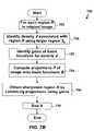
- FIG. 7Ba flowchart is shown of a method 720 that is used in one embodiment of the present invention by the system 600 to perform density or gray level-dependent sharpening using the basis functions B. Examples of techniques for generating the basis functions and associated gains will be described below with respect to FIGS. 2A-2D . Note that the basis functions B and the associated gains may be precomputed prior to the performance of the method 720 in FIG. 7B .
- the method 720enters a loop over each region R (e.g., each pixel) in the original image 602 (step 702 ).
- the method 720identifies the local density d of region R using a larger region S 0 that is a superset of R (step 704 ). Steps 702 and 704 may be performed in the manner described above with respect to FIG. 7A .
- the method 720identifies gains of the basis functions B for density d (step 722 ).
- the method 720computes projections P of the original image 602 onto the basis functions B (step 724 ).
- the method 720obtains a sharpened version of the region R by combining the projections P using the identified gains (step 726 ).
- the method 700repeats steps 704 , 722 , 724 , and 726 for the remaining regions in the original image 602 , thereby producing sharpened image 606 (step 710 ).
- the choice of the basis functionsis governed by two considerations.
- the basis functionsare chosen such that there is minimal perceivable degradation from the desired sharpening filter to the one that is achievable using the basis functions.
- the basis functionsare chosen such that the high frequency regime has low frequency resolution and the low frequency regime has high frequency resolution.
- FIG. 5a graph 500 of one set of basis functions 504 a - d having these properties is shown according to one embodiment of the present invention.
- amplitudeaxis 502 b
- frequencyaxis 502 a
- the basis functions 504 a - dbecome progressively broader at increasing frequencies.
- Such a set of basis functions 504 a - dmay be generated efficiently using a recursive multi-resolution framework, as will now be described in more detail.
- FIG. 6Ba block diagram is shown of a system 610 for performing density-dependent sharpening according to one embodiment of the present invention.
- the system 610includes a printer 620 for printing a digital image.
- Media blurring 622is introduced into the image 612 when the printed image 624 is viewed by the human eye.
- the sharpening filter 604is introduced prior to the printer 620 to “pre-sharpen” an original input digital image 612 .
- the filter 604includes basis functions 614 .
- the filter 604produces a pre-sharpened image 616 that is input to the printer 620 , with the intent that the resulting printed image 624 produced by the printer 620 and viewed by the human eye will be the same as the original input image 612 .
- FIG. 2Aa flowchart is shown of a method 200 that is used in one embodiment of the present invention to compute projections of the original 612 image onto the basis functions 614 .
- the original image at that resolutionis split into two frequency bands: a high-pass band and a low-pass band.
- x b (l) and x h (l)denote the low-pass and high-pass image, respectively, at level l.
- the method 200initializes the representation of the original image 602 at resolution level 0 to be equal to the original image 602 (step 201 ), as indicated by Equation 1.
- the method 200enters a loop over each resolution level l (step 202 ).
- the method 200computes the projection P of the original image 602 onto the basis function B for resolution l (step 203 ).
- the method 200repeats step 203 for the remaining resolutions (step 204 ).
- the result of the method 200is a plurality of projections P of the original image 602 , one for each of the resolutions.
- the method 200may be implemented in any of a variety of ways. For example, referring to FIG. 2B , a flowchart is shown of a method 205 that is used in one embodiment of the present invention to compute projections of the original image 612 onto the basis functions 614 , and thereby to implement the method 200 ( FIG. 2A ).
- the method 205initializes the representation of the original image 612 , as described above with respect to FIG. 2A (step 201 ).
- the method 200enters a loop over each resolution level l (step 202 ).
- the method 200obtains x (l+1) , the representation of the original image 612 at resolution level l+1, such as by using Equation 2 (step 206 ).
- the method 200may obtain low- and high-pass images at all resolution levels by repeating steps 206 - 208 (step 204 ).
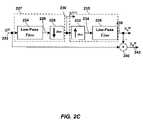
- FIG. 2Ca block diagram is shown which represents one layer of the multi-resolution decomposition process described above with respect to Equation 1-Equation 4 (i.e., one iteration of the loop in FIG. 2B ).
- decdenotes the down-sampling factor.
- the image x (l) 222 at resolution lis provided to a low-pass filter 224 , which produces a low-pass image 226 , which is in turn provided to a down-sampling operator 228 , which produces the image x (l+1) 230 at layer l+1.
- the down-sampling operator 228decreases the sampling rate by throwing away intermediate samples.
- the low-pass filter 224 and down-sampling operator 228in combination act as a decimation filter 227 to produce an original image at resolution l+1.
- the image x (l+1) 230represents the output of Equation 2.
- decimation filter 227into a separate low-pass filtering operation 224 and down-sampling operation 228 is for illustrative purposes only. In practice, for the sake of efficiency, the samples that are thrown out by the down-sampling operator 228 need not be computed by the low-pass filter 224 .
- the image x (l+1) 230is provided to an up-sampling operator 232 , which introduces intermediate zero samples to increase the sampling rate of the image x (l+1) 230 to produce an image 234 , which is in turn provided to low-pass filter 236 , which produces the low-pass image x b (l) 238 at resolution l.
- the up-sampling operator 232 and low-pass filter 236in combination act as an interpolation filter 235 .
- the image x b (l) 238represents the output of Equation 3.
- an adder 240subtracts the low-pass image x b (l) 238 from the original image x (l) 222 to produce the high-pass image x h (l) 242 at resolution l, representing the output of Equation 4.
- FIG. 2Cmay be duplicated for each layer l to produce the low-pass image x b (l) and the high-pass image x h (l) for each layer (i.e., for 0 ⁇ 1 ⁇ L).
- Equation 1Equation 2, and Equation 3 it may be seen that the impulse response of the filter that produces the low-pass image is given as I l+1 l I l l+1 ⁇ (l) and that the impulse response of the filter that produces the high-pass image is given as (1 ⁇ I l+1 l I l l+1 ) ⁇ (l) , where ⁇ (l) is the Kronecker delta function at resolution l.
- Sharpeningmay be achieved by gaining the high-pass image x h at each resolution (i.e., for 0 ⁇ 1 ⁇ L), and then reconstructing the image using the gained-up high-pass images.
- the gainsare selected to be functions of the local gray level and the resolution.
- image x g (l)denote the local gray level information at resolution l
- g(•,l)denote a function that gives the gain as a function of gray level and resolution.
- x s (l)denote the sharpened image at resolution l.
- x s (L)x (L) Equation 5
- x g (l)the local gray level that modulates the gain on the high-pass component in a space-varying fashion. Consequently, the computation of the image x g (l) would depend on the support of the locality that influences the blurring of the image.
- ⁇ (l)specifies the attenuation on the high-pass channel.
- the ⁇ (l)'sare restricted such that ⁇ (l) ⁇ (l+1) ⁇ 1, ⁇ l, since x g (l) will typically be a low-pass version of x (l) .
- the techniques described above for generating the sharpened image x s (0)are illustrated in the flowchart shown in FIG. 2D .
- the method 250 shown in FIG. 2 Dinitializes the sharpened image x s (l) at the coarsest resolution L to be the same as the original image x (L) at resolution L (step 252 ).
- the method 250sets the value of l to be equal to L ⁇ 1 (step 254 ).
- the method 250identifies the gain image G to be applied to resolution l (step 256 ), such as by applying Equation 8 to identify x g (l) and then identifying the gain image G as (1+g(x g (l) ,l)).
- the method 250identifies the projection P to apply to resolution l (step 258 ).
- the high-pass image x h (l)may be used as the projection of the original image onto the basis function B, in which case step 258 may be implemented using Equation 4.
- the method 250interpolates the sharpened image from resolution l+1 to resolution l (step 260 ).
- the method 250multiplies the projection P by the gain G to obtain PG (step 262 ).
- the method 240adds the results of steps 260 and 262 to obtain x s (l) , the sharpened image at resolution l (step 264 ).
- the same dependency map 400may also be used for interpolation purposes, but in this case one would need to employ nearest-neighbor interpolation, resulting in undesirable blocking artifacts in the image.
- the next-best alternative from a minimal computation point of viewis to choose linear interpolation with a data flow map 410 , as shown in FIG. 4 .
- performing the density-dependent sharpening algorithm in the embodiments described aboveinvolves the storage of two additional images at the different resolution levels, namely the gain image x g and the sharpened image x s . It may be difficult to provide such storage, especially in an embedded environment. Therefore, instead of performing multi-resolution decomposition into the basis functions and subsequent sharpening on the entire source image 612 as a whole, those of ordinary skill in the art will understand how to perform decimation and interpolation on portions of the image 612 in a blockwise fashion, thereby reducing the memory requirements of the sharpening filter 604 .
- the sharpened image 606is constructed by modulating and summing the high-pass images at the different layers.
- the high-pass channelstherefore form a basis for the sharpened image x s .
- the original image at the coarsest resolution Li.e., x (L)
- x (L)is also a basis function, but since it is not modulated, we focus only on the high-pass channels.
- the gain function g(d,l) in Equation 6is a function of both density and the resolution layer. It was stated above with respect to step 256 of the method 250 shown in FIG. 2D that the gain G for a layer l may be identified. Examples of techniques for estimating the gain function g(d,l) will now be described. Once the gain function g(d,l) has been estimated, it may be used, for example, to implement step 256 in the manner described above. Referring to FIG. 2E , a flowchart is shown of a method 280 for estimating the gain function g(d,l) in one embodiment of the present invention.
- ndenotes the spatial position of the impulse.
- the impulse response of the different layersis not shift-invariant; hence the need to include the spatial position of the input impulse in the notation for the impulse response.
- the number of unique phases for the impulse response of layer lis dec l+1 , where dec is the down-sampling factor 218 .
- This non-uniqueness of the basis functionposes a problem for determining the modulation coefficients or gain values of each layer. Since natural images would have edges at all possible positions, in one embodiment of the present invention, all of the dec l+1 impulse responses of layer l are averaged to obtain the basis function for that layer.
- Equation 11H ln denote the Fourier transform of h ln . Then the average basis function H 1 in the frequency domain is given by Equation 11:
- Equation 11e j2 ⁇ nf is a factor that spatially aligns all the different phases of the impulse response. Note that H ln may be complex if the impulse response for phase n is asymmetric. However, the average response is always symmetric and therefore H l (•) is real.
- the method 280enters a loop over each resolution l (step 282 ) and identifies the average basis function H l using, for example, Equation 11 (step 284 ).
- the method 280repeats step 284 for each layer l (step 286 ).
- Hdenote a matrix whose columns are the high-pass basis functions computed at a discrete set of frequencies by this repeated application of Equation 11.
- the basis functions 504 a - d for a 4-layer decompositionare shown where the decimation factor 218 is chosen to be 2 and linear interpolation and averaging are employed for interpolation and decimation operations, respectively. Note how the frequency resolution of the basis function increases as the spatial resolution of the layer decreases (along axis 502 a ).
- the method 280enters a loop over each density d (step 288 ) and identifies the desired frequency response at density d (step 290 ).
- Equation 12g(d,•) denotes a column vector containing the gains for each layer at print density d, and 1 denotes a column vector of all ones.
- S(d) ⁇ 1instead of S(d) in the least squares fit because, as previously noted, g(d,•) represents the additional contribution of the high-pass channel in the sharpened image over and above the original contribution.
- the method 280identifies the gains g(d,•) for density d based on the average basis functions H and the desired frequency response S(d) using, for example, Equation 12 (step 292 ).
- the method 280repeats steps 290 - 292 for the remaining densities and thereby identifies the corresponding gains (step 294 ).
- the desired frequency response S(f,d)is typically estimated from print samples and may suffer from high noise because of an inversion that needs to be performed as discussed in more detailed below.
- it is desirable to do a weighted least square fit. Since we are interested in the perceived sharpness of the printed image 624 , in one embodiment of the present invention we choose the contrast sensitivity function of the eye as the weighting function in the frequency domain. Let E denote a diagonal matrix containing the frequency response of the contrast sensitivity function. Then the layer gains are obtain using Equation 13: g ( d ,•)( H T EH ) ⁇ 1 H T E ( S ( d ) ⁇ 1) Equation 13
- Step 292 of method 280may include a step of identifying a weighting function (such as E) (step 302 ) and then identifying the gains for density d based on the average basis functions H, the weighting function E, and the desired frequency response S(d) using Equation 13 (step 304 ).
- a weighting functionsuch as E
- Equation 13may yield negative values for the gains of some layers for some desired response.
- the basis functions which result in such negative gainsare eliminated (e.g., by eliminating the columns of such basis functions from the matrix H).
- the weighted least squares fitis then redone, using only the remaining basis functions.
- the gains of the eliminated basis functionsare then set to zero.
- This techniquemay be applied, for example, by implementing step 292 of method 280 ( FIG. 2E ) in the manner illustrated in FIG. 2G .
- An initial set of gains g(d,•)is identified using, for example, Equation 12 (step 306 ). If none of the gains identified in step 306 is negative (step 308 ), the identified gains are retained for subsequent use in the sharpening filter 604 (step 310 ). If any of the gains is negative, the basis functions corresponding to such negative gains are discarded (step 312 ), the corresponding gains are set to zero (step 314 ), and the gains for the remaining basis functions are recomputed (step 306 ). Steps 306 , 308 , 312 , and 314 may be repeated as necessary to produce all non-negative gains.
- the entire sharpening system 610is shown according to one embodiment of the present invention.
- the density-dependent sharpening filter 604precedes the printer 620 and the subsequent media blurring 622 .
- the density-dependent sharpening filter 604sharpens the input image 612 to produce pre-sharpened image 616 , such that when operated upon by the system blur 618 (i.e., the combination of the media blur 622 and any blurring introduced by the printer 620 ), the original image 612 is reproduced in the printed image 624 .
- the order of the density-dependent sharpening filter 604 and the system blur 618are swapped, as shown in the system 630 of FIG. 6C .
- the system blur 618produces a blurred image 632 , which is sharpened by the density-dependent sharpening filter 604 to produce the (sharpened) printed image 624 .
- the system 630 shown in FIG. 6Cis equivalent to the system 610 shown in FIG. 6B if the system blur 618 and density-dependent filter 604 are linear systems. If they are not linear systems, the swap is valid so long as the system blur 618 and density-dependent filter 604 are locally linear.
- the advantage of the embodiment illustrated in FIG. 6Cis that the input and output of the density-dependent sharpening filter 604 are readily available, so that the desired frequency response of the filter 604 can be easily computed.
- a flowchartis shown of a method 320 that is performed in one embodiment of the present invention to estimate the desired sharpening response.
- the method 320enters a loop over each density d in the density range of the printer 620 (step 322 ).
- a step-edge with mean density dis printed (step 324 ), and the step-edge is scanned (step 326 ).
- the amplitudes of the step-edgesmay be selected to be small to ensure that the entire system 630 can be approximated as a linear system for these edges. If the amplitude of a step-edge is large, the two halves of the edge may be treated independently, since the response on the two ends will be different, given the large density variation.
- the line spread function of the step-edgeis computed (step 328 ), and the frequency transform of the line spread function is taken (step 330 ).
- the resultrepresents the frequency response of the printer/media system 630 .
- the frequency response of the printer/media system 630is inverted (step 332 ). Steps 324 - 332 may be repeated for each density d to obtain the desired response at each density.
- FIG. 8Ashows the estimated layer gain.
- the layer with the largest gaindepends on the print dpi and the viewing distance of the print.
- the print dpiwas 300 and the viewing distance was assumed to be 18 inches.
- layer 1has the largest gain since the layer's frequency response coincides with the peak in the contrast sensitivity function of the eye.
- the finest resolution layer 0has a very large gain due to the large high-frequency noise present in the estimate of S(d).
- the gain for layer 0is reasonable, as seen in FIG. 8A .
- the upper layersare only employed at low densities and disappear at the higher densities. This would make the sharpening filter support vary from approximately 32 pixels at the low density end to approximately 8 pixels at the high density end. This effect is clearly seen in FIG. 8B , which shows a number of step edges at various density levels processed using the density-dependent sharpening algorithm using the gains shown in FIG. 8A .
- graph 900compares the sharpness of the printed edges in a printer/media system with no density-dependent sharpening (curve 904 a ) to the system shown in FIG. 6C , in which the density-dependent filter 604 acts as an inverse system to the printer/media blurring 618 (curve 904 b ).
- the density-dependent sharpening filter 604effectively flattens the SQF, making it independent of the print density. There is a gain of 35 SQF units at the low density and a gain of 18 SQF units at the high density end.
- Embodiments of the present inventionhave a variety of advantages including, but not limited to, the following.
- embodiments of the present inventionenable sharpening to be performed in a manner that is density-dependent, with more sharpening being performed for densities in which more blurring occurs.
- lower densitiesare more susceptible to blurring than higher densities.
- embodiments of the present inventionmay be applied to perform more sharpening in regions of lower density than in regions of higher density.
- the techniques disclosed hereinmay apply a variable degree of sharpening within a single image in a manner that is tailored to the amount of blurring. The techniques disclosed herein may therefore obtain sharpening where and to the extent that it is necessary, without obtaining the detriments of sharpening where sharpening is not necessary.
- Another advantage of embodiments of the present inventionis that the use of the multi-resolution framework enables sharpening to be performed with a high degree of computational efficiency.
- the source imageis decomposed into multiple images at multiple resolutions. Filtering the lower-resolution images is significantly less computationally intensive than performing filtering on the entire image. Performing filtering on these lower-resolution images and recombining them produces high-quality sharpening without incurring the computational cost that would be incurred by filtering the entire image using conventional techniques.
- the techniques disclosed hereinare not limited to use in conjunction with the media 100 . Rather, the techniques disclosed herein may be used in conjunction with media having any number of layers and any combination of colors.
- the imaging layer(s)may be located anywhere within the structure of the media.
- the techniques described abovemay be implemented, for example, in hardware, software, firmware, or any combination thereof.
- the techniques described abovemay be implemented in one or more computer programs executing on a programmable computer including a processor, a storage medium readable by the processor (including, for example, volatile and non-volatile memory and/or storage elements), at least one input device, and at least one output device.
- Program codemay be applied to input entered using the input device to perform the functions described and to generate output.
- the outputmay be provided to one or more output devices.
- Each computer program within the scope of the claims belowmay be implemented in any programming language, such as assembly language, machine language, a high-level procedural programming language, or an object-oriented programming language.
- the programming languagemay, for example, be a compiled or interpreted programming language.
- Each such computer programmay be implemented in a computer program product tangibly embodied in a machine-readable storage device for execution by a computer processor.
- Method steps of the inventionmay be performed by a computer processor executing a program tangibly embodied on a computer-readable medium to perform functions of the invention by operating on input and generating output.
- Suitable processorsinclude, by way of example, both general and special purpose microprocessors.
- the processorreceives instructions and data from a read-only memory and/or a random access memory.
- Storage devices suitable for tangibly embodying computer program instructionsinclude, for example, all forms of non-volatile memory, such as semiconductor memory devices, including EPROM, EEPROM, and flash memory devices; magnetic disks such as internal hard disks and removable disks; magneto-optical disks; and CD-ROMs. Any of the foregoing may be supplemented by, or incorporated in, specially-designed ASICs (application-specific integrated circuits) or FPGAs (Field-Programmable Gate Arrays).
- a computercan generally also receive programs and data from a storage medium such as an internal disk (not shown) or a removable disk.
Landscapes
- Engineering & Computer Science (AREA)
- Multimedia (AREA)
- Signal Processing (AREA)
- Physics & Mathematics (AREA)
- General Physics & Mathematics (AREA)
- Theoretical Computer Science (AREA)
- Image Processing (AREA)
- Facsimile Image Signal Circuits (AREA)
Abstract
Description
x(0)=x Equation 1
x(l+1)=Ill+1x(l),l=0, . . . , L−1
xb(l)=Il+1lx(l+1) Equation 3
xh(l)=x(l)−xb(l) Equation 4
xs(L)=x(L) Equation 5
xs(l)=Il+1lxs(l+1)+(1+g(xg(l),l))xh(l), l=L−1, . . . , 0 Equation 6
xg(L)=x(L) Equation 7
xg(l)=Il+1lxg(l+1)+β(l)xh(l),l=L−1, . . . ,0 Equation 8
xg(l)=ILlxgL,l=L−1, . . . ,0 Equation 9
hln=Il0(1−Il+1lIll+1)I0lδn(0)
g(d,•)=(HTH)−1HT(S(d)−1) Equation 12
g(d,•)=(HTEH)−1HTE(S(d)−1) Equation 13
Claims (22)
Priority Applications (8)
| Application Number | Priority Date | Filing Date | Title |
|---|---|---|---|
| US10/960,143US7373011B2 (en) | 2004-10-07 | 2004-10-07 | Density-dependent sharpening |
| CN2005800420651ACN101073251B (en) | 2004-10-07 | 2005-10-06 | Density-dependent sharpening |
| JP2007535842AJP4883716B2 (en) | 2004-10-07 | 2005-10-06 | Density-dependent sharpening |
| EP05808927AEP1797709A1 (en) | 2004-10-07 | 2005-10-06 | Density-dependent sharpening |
| CA002583416ACA2583416A1 (en) | 2004-10-07 | 2005-10-06 | Density-dependent sharpening |
| KR1020077010386AKR20070063031A (en) | 2004-10-07 | 2005-10-06 | Density Dependent Sharpening |
| PCT/US2005/036187WO2006042126A1 (en) | 2004-10-07 | 2005-10-06 | Density-dependent sharpening |
| JP2010250115AJP2011040098A (en) | 2004-10-07 | 2010-11-08 | Density-dependent sharpening |
Applications Claiming Priority (1)
| Application Number | Priority Date | Filing Date | Title |
|---|---|---|---|
| US10/960,143US7373011B2 (en) | 2004-10-07 | 2004-10-07 | Density-dependent sharpening |
Publications (2)
| Publication Number | Publication Date |
|---|---|
| US20060077470A1 US20060077470A1 (en) | 2006-04-13 |
| US7373011B2true US7373011B2 (en) | 2008-05-13 |
Family
ID=35559415
Family Applications (1)
| Application Number | Title | Priority Date | Filing Date |
|---|---|---|---|
| US10/960,143Expired - Fee RelatedUS7373011B2 (en) | 2004-10-07 | 2004-10-07 | Density-dependent sharpening |
Country Status (7)
| Country | Link |
|---|---|
| US (1) | US7373011B2 (en) |
| EP (1) | EP1797709A1 (en) |
| JP (2) | JP4883716B2 (en) |
| KR (1) | KR20070063031A (en) |
| CN (1) | CN101073251B (en) |
| CA (1) | CA2583416A1 (en) |
| WO (1) | WO2006042126A1 (en) |
Cited By (3)
| Publication number | Priority date | Publication date | Assignee | Title |
|---|---|---|---|---|
| US20090285504A1 (en)* | 2008-05-15 | 2009-11-19 | Arcsoft, Inc. | Method for estimating noise according to multiresolution model |
| US20130033586A1 (en)* | 2010-04-21 | 2013-02-07 | Samir Hulyalkar | System, Method and Apparatus for Generation, Transmission and Display of 3D Content |
| US20220405889A1 (en)* | 2021-06-22 | 2022-12-22 | Ati Technologies Ulc | Sharpening of images in non-linear and linear formats |
Families Citing this family (9)
| Publication number | Priority date | Publication date | Assignee | Title |
|---|---|---|---|---|
| EP1821257B1 (en)* | 2006-02-15 | 2010-08-04 | Sony Deutschland GmbH | Method for processing digital image data |
| US7724980B1 (en) | 2006-07-24 | 2010-05-25 | Adobe Systems Incorporated | System and method for selective sharpening of images |
| US8538200B2 (en)* | 2008-11-19 | 2013-09-17 | Nec Laboratories America, Inc. | Systems and methods for resolution-invariant image representation |
| TWI413019B (en)* | 2010-12-07 | 2013-10-21 | Novatek Microelectronics Corp | Image adjusting circuit and image adjusting method |
| GB2501402B (en)* | 2010-12-21 | 2015-06-24 | Syndiant Inc | Spatial light modulator with storage reducer |
| CN107079094B (en)* | 2014-09-30 | 2018-07-13 | 富士胶片株式会社 | Image processing apparatus, image processing method and recording medium |
| WO2016052004A1 (en)* | 2014-09-30 | 2016-04-07 | 富士フイルム株式会社 | Image processing device, filter acquisition device, image processing method, filter acquisition method, program, and recording medium |
| US10075661B2 (en)* | 2015-03-18 | 2018-09-11 | Sony Corporation | Image processing apparatus, image processing method, and image capturing apparatus |
| CN109497887B (en)* | 2018-11-06 | 2020-10-30 | 浙江义乌舒美佳科技股份有限公司 | Safety barrel type dust collector |
Citations (15)
| Publication number | Priority date | Publication date | Assignee | Title |
|---|---|---|---|---|
| JPS58151773A (en) | 1982-03-05 | 1983-09-09 | Nec Corp | Facsimile capable of correcting intermediate gradation |
| JPS61230571A (en) | 1985-04-05 | 1986-10-14 | Dainippon Screen Mfg Co Ltd | Intensifying method for sharpness in picture scanning/ recording |
| JPH0336672A (en) | 1989-07-03 | 1991-02-18 | Nec Corp | Sharpening method for picture |
| US5392137A (en) | 1992-04-30 | 1995-02-21 | Ricoh Company, Ltd. | Image processing apparatus in which filtering is selected for input image characteristics |
| JPH07274004A (en) | 1994-03-29 | 1995-10-20 | Dainippon Screen Mfg Co Ltd | Sharpness emphasizing device for picture |
| US5867606A (en) | 1997-08-12 | 1999-02-02 | Hewlett-Packard Company | Apparatus and method for determining the appropriate amount of sharpening for an image |
| US6252995B1 (en) | 1997-08-25 | 2001-06-26 | Fuji Photo Film Co., Ltd. | Method of and apparatus for enhancing image sharpness |
| JP2001197311A (en) | 2000-01-14 | 2001-07-19 | Sharp Corp | Image processing device |
| US6304341B1 (en) | 1994-12-20 | 2001-10-16 | Canon Kabushiki Kaisha | Image processing method and apparatus and image forming method and apparatus using the same |
| US6411305B1 (en) | 1999-05-07 | 2002-06-25 | Picsurf, Inc. | Image magnification and selective image sharpening system and method |
| US20020097439A1 (en) | 2001-01-23 | 2002-07-25 | Oak Technology, Inc. | Edge detection and sharpening process for an image |
| US20020163670A1 (en) | 2001-03-30 | 2002-11-07 | Masayuki Takahira | Image processing method and apparatus, and recording medium |
| EP1330114A2 (en) | 2002-01-16 | 2003-07-23 | Noritsu Koki Co., Ltd. | Method and apparatus for improving sharpness of images |
| US6807299B2 (en)* | 2001-03-10 | 2004-10-19 | Hewlett-Packard Development Company, L.P. | Method for contrast mapping of digital images that converges on a solution |
| US7269300B2 (en)* | 2003-10-24 | 2007-09-11 | Eastman Kodak Company | Sharpening a digital image in accordance with magnification values |
Family Cites Families (10)
| Publication number | Priority date | Publication date | Assignee | Title |
|---|---|---|---|---|
| JP3738788B2 (en)* | 1995-09-29 | 2006-01-25 | 富士写真フイルム株式会社 | Image dynamic range compression processing method and apparatus |
| JP3816151B2 (en)* | 1995-09-29 | 2006-08-30 | 富士写真フイルム株式会社 | Image processing method and apparatus |
| JP4267159B2 (en)* | 1999-01-26 | 2009-05-27 | 富士フイルム株式会社 | Image processing method and apparatus, and recording medium |
| US7068851B1 (en)* | 1999-12-10 | 2006-06-27 | Ricoh Co., Ltd. | Multiscale sharpening and smoothing with wavelets |
| JP2002183727A (en)* | 2000-12-19 | 2002-06-28 | Konica Corp | Image processing device |
| JP4187134B2 (en)* | 2001-02-20 | 2008-11-26 | 株式会社リコー | Image processing apparatus, image processing method, program for executing the method, and recording medium storing the program |
| JP3918084B2 (en)* | 2001-04-02 | 2007-05-23 | 富士フイルム株式会社 | Image processing method, photographing apparatus, photographing system, and printer |
| JP4141712B2 (en)* | 2002-03-20 | 2008-08-27 | 株式会社リコー | Image processing device |
| JP2004086456A (en)* | 2002-08-26 | 2004-03-18 | Canon Inc | Image processing device |
| JP4359840B2 (en)* | 2004-07-23 | 2009-11-11 | 株式会社エムアンドシー | Image processing apparatus and image processing method |
- 2004
- 2004-10-07USUS10/960,143patent/US7373011B2/ennot_activeExpired - Fee Related
- 2005
- 2005-10-06CNCN2005800420651Apatent/CN101073251B/ennot_activeExpired - Fee Related
- 2005-10-06WOPCT/US2005/036187patent/WO2006042126A1/enactiveApplication Filing
- 2005-10-06CACA002583416Apatent/CA2583416A1/ennot_activeAbandoned
- 2005-10-06JPJP2007535842Apatent/JP4883716B2/ennot_activeExpired - Fee Related
- 2005-10-06KRKR1020077010386Apatent/KR20070063031A/ennot_activeAbandoned
- 2005-10-06EPEP05808927Apatent/EP1797709A1/ennot_activeWithdrawn
- 2010
- 2010-11-08JPJP2010250115Apatent/JP2011040098A/enactivePending
Patent Citations (15)
| Publication number | Priority date | Publication date | Assignee | Title |
|---|---|---|---|---|
| JPS58151773A (en) | 1982-03-05 | 1983-09-09 | Nec Corp | Facsimile capable of correcting intermediate gradation |
| JPS61230571A (en) | 1985-04-05 | 1986-10-14 | Dainippon Screen Mfg Co Ltd | Intensifying method for sharpness in picture scanning/ recording |
| JPH0336672A (en) | 1989-07-03 | 1991-02-18 | Nec Corp | Sharpening method for picture |
| US5392137A (en) | 1992-04-30 | 1995-02-21 | Ricoh Company, Ltd. | Image processing apparatus in which filtering is selected for input image characteristics |
| JPH07274004A (en) | 1994-03-29 | 1995-10-20 | Dainippon Screen Mfg Co Ltd | Sharpness emphasizing device for picture |
| US6304341B1 (en) | 1994-12-20 | 2001-10-16 | Canon Kabushiki Kaisha | Image processing method and apparatus and image forming method and apparatus using the same |
| US5867606A (en) | 1997-08-12 | 1999-02-02 | Hewlett-Packard Company | Apparatus and method for determining the appropriate amount of sharpening for an image |
| US6252995B1 (en) | 1997-08-25 | 2001-06-26 | Fuji Photo Film Co., Ltd. | Method of and apparatus for enhancing image sharpness |
| US6411305B1 (en) | 1999-05-07 | 2002-06-25 | Picsurf, Inc. | Image magnification and selective image sharpening system and method |
| JP2001197311A (en) | 2000-01-14 | 2001-07-19 | Sharp Corp | Image processing device |
| US20020097439A1 (en) | 2001-01-23 | 2002-07-25 | Oak Technology, Inc. | Edge detection and sharpening process for an image |
| US6807299B2 (en)* | 2001-03-10 | 2004-10-19 | Hewlett-Packard Development Company, L.P. | Method for contrast mapping of digital images that converges on a solution |
| US20020163670A1 (en) | 2001-03-30 | 2002-11-07 | Masayuki Takahira | Image processing method and apparatus, and recording medium |
| EP1330114A2 (en) | 2002-01-16 | 2003-07-23 | Noritsu Koki Co., Ltd. | Method and apparatus for improving sharpness of images |
| US7269300B2 (en)* | 2003-10-24 | 2007-09-11 | Eastman Kodak Company | Sharpening a digital image in accordance with magnification values |
Cited By (5)
| Publication number | Priority date | Publication date | Assignee | Title |
|---|---|---|---|---|
| US20090285504A1 (en)* | 2008-05-15 | 2009-11-19 | Arcsoft, Inc. | Method for estimating noise according to multiresolution model |
| US8000556B2 (en)* | 2008-05-15 | 2011-08-16 | Arcsoft, Inc. | Method for estimating noise according to multiresolution model |
| US20130033586A1 (en)* | 2010-04-21 | 2013-02-07 | Samir Hulyalkar | System, Method and Apparatus for Generation, Transmission and Display of 3D Content |
| US20220405889A1 (en)* | 2021-06-22 | 2022-12-22 | Ati Technologies Ulc | Sharpening of images in non-linear and linear formats |
| US12020408B2 (en)* | 2021-06-22 | 2024-06-25 | Ati Technologies Ulc | Sharpening of images in non-linear and linear formats |
Also Published As
| Publication number | Publication date |
|---|---|
| JP4883716B2 (en) | 2012-02-22 |
| KR20070063031A (en) | 2007-06-18 |
| WO2006042126A1 (en) | 2006-04-20 |
| JP2008516345A (en) | 2008-05-15 |
| EP1797709A1 (en) | 2007-06-20 |
| CA2583416A1 (en) | 2006-04-20 |
| CN101073251A (en) | 2007-11-14 |
| CN101073251B (en) | 2010-05-12 |
| JP2011040098A (en) | 2011-02-24 |
| US20060077470A1 (en) | 2006-04-13 |
Similar Documents
| Publication | Publication Date | Title |
|---|---|---|
| JP2011040098A (en) | Density-dependent sharpening | |
| US7280703B2 (en) | Method of spatially filtering a digital image using chrominance information | |
| Zhang et al. | Adaptive bilateral filter for sharpness enhancement and noise removal | |
| Lieberman et al. | A dual interpretation for direct binary search and its implications for tone reproduction and texture quality | |
| US5867606A (en) | Apparatus and method for determining the appropriate amount of sharpening for an image | |
| US7512288B1 (en) | Image blending using non-affine interpolation | |
| US20030161545A1 (en) | Method for sharpening a digital image with signal to noise estimation | |
| US6891977B2 (en) | Method for sharpening a digital image without amplifying noise | |
| EP1722330B1 (en) | A method and system for extending binary image data to contone image data | |
| US7120305B2 (en) | Adaptive nonlinear image enlargement using wavelet transform coefficients | |
| JP2000050081A (en) | Automatic tone control method by contrast gain control of edge | |
| JP2001136388A (en) | Adaptive error diffusion method | |
| US20100266183A1 (en) | Method of Generating a Multiscale Contrast Enhanced IMage | |
| Sun et al. | Scanned image descreening with image redundancy and adaptive filtering | |
| US8457434B2 (en) | Spatial diffusion in images | |
| EP2198402B1 (en) | Method of generating a multiscale contrast enhanced image | |
| Zhang et al. | On kernel selection of multivariate local polynomial modelling and its application to image smoothing and reconstruction | |
| Occorsio et al. | Image scaling by de la Vallée-Poussin filtered interpolation | |
| US7817871B2 (en) | Scaling of raster images without blurring of edges | |
| JP2011024049A (en) | Image processing apparatus, and method therein | |
| Ignácio et al. | Block-based image inpainting in the wavelet domain | |
| US7636488B2 (en) | User adjustable image enhancement filtering | |
| US20040169872A1 (en) | Blind inverse halftoning | |
| US6167414A (en) | System for adjusting size and scale of digital filters and creating digital filters | |
| Bonnier et al. | Measurement and compensation of printer modulation transfer function |
Legal Events
| Date | Code | Title | Description |
|---|---|---|---|
| AS | Assignment | Owner name:POLAROID CORPORATION, MASSACHUSETTS Free format text:ASSIGNMENT OF ASSIGNORS INTEREST;ASSIGNOR:SAQUIB, SUHAIL S.;REEL/FRAME:015881/0751 Effective date:20041007 | |
| AS | Assignment | Owner name:WILMINGTON TRUST COMPANY, AS COLLATERAL AGENT, DEL Free format text:ASSIGNMENT OF ASSIGNORS INTEREST;ASSIGNORS:POLAROLD HOLDING COMPANY;POLAROID CORPORATION;POLAROID ASIA PACIFIC LLC;AND OTHERS;REEL/FRAME:016602/0332 Effective date:20050428 Owner name:JPMORGAN CHASE BANK,N.A,AS ADMINISTRATIVE AGENT, W Free format text:SECURITY INTEREST;ASSIGNORS:POLAROID HOLDING COMPANY;POLAROID CORPORATION;POLAROID ASIA PACIFIC LLC;AND OTHERS;REEL/FRAME:016602/0603 Effective date:20050428 Owner name:WILMINGTON TRUST COMPANY, AS COLLATERAL AGENT,DELA Free format text:SECURITY AGREEMENT;ASSIGNORS:POLAROLD HOLDING COMPANY;POLAROID CORPORATION;POLAROID ASIA PACIFIC LLC;AND OTHERS;REEL/FRAME:016602/0332 Effective date:20050428 Owner name:JPMORGAN CHASE BANK,N.A,AS ADMINISTRATIVE AGENT,WI Free format text:SECURITY INTEREST;ASSIGNORS:POLAROID HOLDING COMPANY;POLAROID CORPORATION;POLAROID ASIA PACIFIC LLC;AND OTHERS;REEL/FRAME:016602/0603 Effective date:20050428 Owner name:WILMINGTON TRUST COMPANY, AS COLLATERAL AGENT, DEL Free format text:SECURITY AGREEMENT;ASSIGNORS:POLAROLD HOLDING COMPANY;POLAROID CORPORATION;POLAROID ASIA PACIFIC LLC;AND OTHERS;REEL/FRAME:016602/0332 Effective date:20050428 | |
| AS | Assignment | Owner name:POLAROID HOLDING COMPANY, MASSACHUSETTS Free format text:RELEASE OF SECURITY INTEREST IN PATENTS;ASSIGNOR:WILMINGTON TRUST COMPANY;REEL/FRAME:019699/0512 Effective date:20070425 Owner name:POLAROID CORPORATION, MASSACHUSETTS Free format text:RELEASE OF SECURITY INTEREST IN PATENTS;ASSIGNOR:WILMINGTON TRUST COMPANY;REEL/FRAME:019699/0512 Effective date:20070425 Owner name:POLAROID CAPITAL LLC, MASSACHUSETTS Free format text:RELEASE OF SECURITY INTEREST IN PATENTS;ASSIGNOR:WILMINGTON TRUST COMPANY;REEL/FRAME:019699/0512 Effective date:20070425 Owner name:POLAROID ASIA PACIFIC LLC, MASSACHUSETTS Free format text:RELEASE OF SECURITY INTEREST IN PATENTS;ASSIGNOR:WILMINGTON TRUST COMPANY;REEL/FRAME:019699/0512 Effective date:20070425 Owner name:POLAROID EYEWEAR LLC, MASSACHUSETTS Free format text:RELEASE OF SECURITY INTEREST IN PATENTS;ASSIGNOR:WILMINGTON TRUST COMPANY;REEL/FRAME:019699/0512 Effective date:20070425 Owner name:POLOROID INTERNATIONAL HOLDING LLC, MASSACHUSETTS Free format text:RELEASE OF SECURITY INTEREST IN PATENTS;ASSIGNOR:WILMINGTON TRUST COMPANY;REEL/FRAME:019699/0512 Effective date:20070425 Owner name:POLAROID INVESTMENT LLC, MASSACHUSETTS Free format text:RELEASE OF SECURITY INTEREST IN PATENTS;ASSIGNOR:WILMINGTON TRUST COMPANY;REEL/FRAME:019699/0512 Effective date:20070425 Owner name:POLAROID LATIN AMERICA I CORPORATION, MASSACHUSETT Free format text:RELEASE OF SECURITY INTEREST IN PATENTS;ASSIGNOR:WILMINGTON TRUST COMPANY;REEL/FRAME:019699/0512 Effective date:20070425 Owner name:POLAROID NEW BEDFORD REAL ESTATE LLC, MASSACHUSETT Free format text:RELEASE OF SECURITY INTEREST IN PATENTS;ASSIGNOR:WILMINGTON TRUST COMPANY;REEL/FRAME:019699/0512 Effective date:20070425 Owner name:POLAROID NORWOOD REAL ESTATE LLC, MASSACHUSETTS Free format text:RELEASE OF SECURITY INTEREST IN PATENTS;ASSIGNOR:WILMINGTON TRUST COMPANY;REEL/FRAME:019699/0512 Effective date:20070425 Owner name:POLAROID WALTHAM REAL ESTATE LLC, MASSACHUSETTS Free format text:RELEASE OF SECURITY INTEREST IN PATENTS;ASSIGNOR:WILMINGTON TRUST COMPANY;REEL/FRAME:019699/0512 Effective date:20070425 Owner name:PETTERS CONSUMER BRANDS, LLC, MASSACHUSETTS Free format text:RELEASE OF SECURITY INTEREST IN PATENTS;ASSIGNOR:WILMINGTON TRUST COMPANY;REEL/FRAME:019699/0512 Effective date:20070425 Owner name:PETTERS CONSUMER BRANDS INTERNATIONAL, LLC, MASSAC Free format text:RELEASE OF SECURITY INTEREST IN PATENTS;ASSIGNOR:WILMINGTON TRUST COMPANY;REEL/FRAME:019699/0512 Effective date:20070425 Owner name:ZINK INCORPORATED, MASSACHUSETTS Free format text:RELEASE OF SECURITY INTEREST IN PATENTS;ASSIGNOR:WILMINGTON TRUST COMPANY;REEL/FRAME:019699/0512 Effective date:20070425 Owner name:POLAROID HOLDING COMPANY,MASSACHUSETTS Free format text:RELEASE OF SECURITY INTEREST IN PATENTS;ASSIGNOR:WILMINGTON TRUST COMPANY;REEL/FRAME:019699/0512 Effective date:20070425 Owner name:POLAROID CORPORATION,MASSACHUSETTS Free format text:RELEASE OF SECURITY INTEREST IN PATENTS;ASSIGNOR:WILMINGTON TRUST COMPANY;REEL/FRAME:019699/0512 Effective date:20070425 Owner name:POLAROID CAPITAL LLC,MASSACHUSETTS Free format text:RELEASE OF SECURITY INTEREST IN PATENTS;ASSIGNOR:WILMINGTON TRUST COMPANY;REEL/FRAME:019699/0512 Effective date:20070425 Owner name:POLAROID ASIA PACIFIC LLC,MASSACHUSETTS Free format text:RELEASE OF SECURITY INTEREST IN PATENTS;ASSIGNOR:WILMINGTON TRUST COMPANY;REEL/FRAME:019699/0512 Effective date:20070425 Owner name:POLAROID EYEWEAR LLC,MASSACHUSETTS Free format text:RELEASE OF SECURITY INTEREST IN PATENTS;ASSIGNOR:WILMINGTON TRUST COMPANY;REEL/FRAME:019699/0512 Effective date:20070425 Owner name:POLOROID INTERNATIONAL HOLDING LLC,MASSACHUSETTS Free format text:RELEASE OF SECURITY INTEREST IN PATENTS;ASSIGNOR:WILMINGTON TRUST COMPANY;REEL/FRAME:019699/0512 Effective date:20070425 Owner name:POLAROID INVESTMENT LLC,MASSACHUSETTS Free format text:RELEASE OF SECURITY INTEREST IN PATENTS;ASSIGNOR:WILMINGTON TRUST COMPANY;REEL/FRAME:019699/0512 Effective date:20070425 Owner name:POLAROID LATIN AMERICA I CORPORATION,MASSACHUSETTS Free format text:RELEASE OF SECURITY INTEREST IN PATENTS;ASSIGNOR:WILMINGTON TRUST COMPANY;REEL/FRAME:019699/0512 Effective date:20070425 Owner name:POLAROID NEW BEDFORD REAL ESTATE LLC,MASSACHUSETTS Free format text:RELEASE OF SECURITY INTEREST IN PATENTS;ASSIGNOR:WILMINGTON TRUST COMPANY;REEL/FRAME:019699/0512 Effective date:20070425 Owner name:POLAROID NORWOOD REAL ESTATE LLC,MASSACHUSETTS Free format text:RELEASE OF SECURITY INTEREST IN PATENTS;ASSIGNOR:WILMINGTON TRUST COMPANY;REEL/FRAME:019699/0512 Effective date:20070425 Owner name:POLAROID WALTHAM REAL ESTATE LLC,MASSACHUSETTS Free format text:RELEASE OF SECURITY INTEREST IN PATENTS;ASSIGNOR:WILMINGTON TRUST COMPANY;REEL/FRAME:019699/0512 Effective date:20070425 Owner name:PETTERS CONSUMER BRANDS, LLC,MASSACHUSETTS Free format text:RELEASE OF SECURITY INTEREST IN PATENTS;ASSIGNOR:WILMINGTON TRUST COMPANY;REEL/FRAME:019699/0512 Effective date:20070425 Owner name:PETTERS CONSUMER BRANDS INTERNATIONAL, LLC,MASSACH Free format text:RELEASE OF SECURITY INTEREST IN PATENTS;ASSIGNOR:WILMINGTON TRUST COMPANY;REEL/FRAME:019699/0512 Effective date:20070425 Owner name:ZINK INCORPORATED,MASSACHUSETTS Free format text:RELEASE OF SECURITY INTEREST IN PATENTS;ASSIGNOR:WILMINGTON TRUST COMPANY;REEL/FRAME:019699/0512 Effective date:20070425 | |
| AS | Assignment | Owner name:POLAROID HOLDING COMPANY, MASSACHUSETTS Free format text:RELEASE OF SECURITY INTEREST IN PATENTS;ASSIGNOR:JPMORGAN CHASE BANK, N.A.;REEL/FRAME:020733/0001 Effective date:20080225 Owner name:POLAROID INTERNATIONAL HOLDING LLC, MASSACHUSETTS Free format text:RELEASE OF SECURITY INTEREST IN PATENTS;ASSIGNOR:JPMORGAN CHASE BANK, N.A.;REEL/FRAME:020733/0001 Effective date:20080225 Owner name:POLAROID INVESTMENT LLC, MASSACHUSETTS Free format text:RELEASE OF SECURITY INTEREST IN PATENTS;ASSIGNOR:JPMORGAN CHASE BANK, N.A.;REEL/FRAME:020733/0001 Effective date:20080225 Owner name:POLAROID LATIN AMERICA I CORPORATION, MASSACHUSETT Free format text:RELEASE OF SECURITY INTEREST IN PATENTS;ASSIGNOR:JPMORGAN CHASE BANK, N.A.;REEL/FRAME:020733/0001 Effective date:20080225 Owner name:POLAROID NEW BEDFORD REAL ESTATE LLC, MASSACHUSETT Free format text:RELEASE OF SECURITY INTEREST IN PATENTS;ASSIGNOR:JPMORGAN CHASE BANK, N.A.;REEL/FRAME:020733/0001 Effective date:20080225 Owner name:POLAROID NORWOOD REAL ESTATE LLC, MASSACHUSETTS Free format text:RELEASE OF SECURITY INTEREST IN PATENTS;ASSIGNOR:JPMORGAN CHASE BANK, N.A.;REEL/FRAME:020733/0001 Effective date:20080225 Owner name:POLAROID WALTHAM REAL ESTATE LLC, MASSACHUSETTS Free format text:RELEASE OF SECURITY INTEREST IN PATENTS;ASSIGNOR:JPMORGAN CHASE BANK, N.A.;REEL/FRAME:020733/0001 Effective date:20080225 Owner name:POLAROID CONSUMER ELECTRONICS, LLC, (FORMERLY KNOW Free format text:RELEASE OF SECURITY INTEREST IN PATENTS;ASSIGNOR:JPMORGAN CHASE BANK, N.A.;REEL/FRAME:020733/0001 Effective date:20080225 Owner name:POLAROID CONSUMER ELECTRONICS INTERNATIONAL, LLC, Free format text:RELEASE OF SECURITY INTEREST IN PATENTS;ASSIGNOR:JPMORGAN CHASE BANK, N.A.;REEL/FRAME:020733/0001 Effective date:20080225 Owner name:ZINK INCORPORATED, MASSACHUSETTS Free format text:RELEASE OF SECURITY INTEREST IN PATENTS;ASSIGNOR:JPMORGAN CHASE BANK, N.A.;REEL/FRAME:020733/0001 Effective date:20080225 Owner name:POLAROID CORPORATION, MASSACHUSETTS Free format text:RELEASE OF SECURITY INTEREST IN PATENTS;ASSIGNOR:JPMORGAN CHASE BANK, N.A.;REEL/FRAME:020733/0001 Effective date:20080225 Owner name:POLAROID ASIA PACIFIC LLC, MASSACHUSETTS Free format text:RELEASE OF SECURITY INTEREST IN PATENTS;ASSIGNOR:JPMORGAN CHASE BANK, N.A.;REEL/FRAME:020733/0001 Effective date:20080225 Owner name:POLAROID CAPITAL LLC, MASSACHUSETTS Free format text:RELEASE OF SECURITY INTEREST IN PATENTS;ASSIGNOR:JPMORGAN CHASE BANK, N.A.;REEL/FRAME:020733/0001 Effective date:20080225 Owner name:PLLAROID EYEWEAR I LLC, MASSACHUSETTS Free format text:RELEASE OF SECURITY INTEREST IN PATENTS;ASSIGNOR:JPMORGAN CHASE BANK, N.A.;REEL/FRAME:020733/0001 Effective date:20080225 Owner name:POLAROID HOLDING COMPANY,MASSACHUSETTS Free format text:RELEASE OF SECURITY INTEREST IN PATENTS;ASSIGNOR:JPMORGAN CHASE BANK, N.A.;REEL/FRAME:020733/0001 Effective date:20080225 Owner name:POLAROID INTERNATIONAL HOLDING LLC,MASSACHUSETTS Free format text:RELEASE OF SECURITY INTEREST IN PATENTS;ASSIGNOR:JPMORGAN CHASE BANK, N.A.;REEL/FRAME:020733/0001 Effective date:20080225 Owner name:POLAROID INVESTMENT LLC,MASSACHUSETTS Free format text:RELEASE OF SECURITY INTEREST IN PATENTS;ASSIGNOR:JPMORGAN CHASE BANK, N.A.;REEL/FRAME:020733/0001 Effective date:20080225 Owner name:POLAROID LATIN AMERICA I CORPORATION,MASSACHUSETTS Free format text:RELEASE OF SECURITY INTEREST IN PATENTS;ASSIGNOR:JPMORGAN CHASE BANK, N.A.;REEL/FRAME:020733/0001 Effective date:20080225 Owner name:POLAROID NEW BEDFORD REAL ESTATE LLC,MASSACHUSETTS Free format text:RELEASE OF SECURITY INTEREST IN PATENTS;ASSIGNOR:JPMORGAN CHASE BANK, N.A.;REEL/FRAME:020733/0001 Effective date:20080225 Owner name:POLAROID NORWOOD REAL ESTATE LLC,MASSACHUSETTS Free format text:RELEASE OF SECURITY INTEREST IN PATENTS;ASSIGNOR:JPMORGAN CHASE BANK, N.A.;REEL/FRAME:020733/0001 Effective date:20080225 Owner name:POLAROID WALTHAM REAL ESTATE LLC,MASSACHUSETTS Free format text:RELEASE OF SECURITY INTEREST IN PATENTS;ASSIGNOR:JPMORGAN CHASE BANK, N.A.;REEL/FRAME:020733/0001 Effective date:20080225 Owner name:ZINK INCORPORATED,MASSACHUSETTS Free format text:RELEASE OF SECURITY INTEREST IN PATENTS;ASSIGNOR:JPMORGAN CHASE BANK, N.A.;REEL/FRAME:020733/0001 Effective date:20080225 Owner name:POLAROID CORPORATION,MASSACHUSETTS Free format text:RELEASE OF SECURITY INTEREST IN PATENTS;ASSIGNOR:JPMORGAN CHASE BANK, N.A.;REEL/FRAME:020733/0001 Effective date:20080225 Owner name:POLAROID ASIA PACIFIC LLC,MASSACHUSETTS Free format text:RELEASE OF SECURITY INTEREST IN PATENTS;ASSIGNOR:JPMORGAN CHASE BANK, N.A.;REEL/FRAME:020733/0001 Effective date:20080225 Owner name:POLAROID CAPITAL LLC,MASSACHUSETTS Free format text:RELEASE OF SECURITY INTEREST IN PATENTS;ASSIGNOR:JPMORGAN CHASE BANK, N.A.;REEL/FRAME:020733/0001 Effective date:20080225 Owner name:PLLAROID EYEWEAR I LLC,MASSACHUSETTS Free format text:RELEASE OF SECURITY INTEREST IN PATENTS;ASSIGNOR:JPMORGAN CHASE BANK, N.A.;REEL/FRAME:020733/0001 Effective date:20080225 | |
| STCF | Information on status: patent grant | Free format text:PATENTED CASE | |
| FEPP | Fee payment procedure | Free format text:PAT HOLDER CLAIMS SMALL ENTITY STATUS, ENTITY STATUS SET TO SMALL (ORIGINAL EVENT CODE: LTOS); ENTITY STATUS OF PATENT OWNER: LARGE ENTITY | |
| AS | Assignment | Owner name:PLR IP HOLDINGS, LLC, MINNESOTA Free format text:NUNC PRO TUNC ASSIGNMENT;ASSIGNOR:POLAROID CORPORATION;REEL/FRAME:023119/0045 Effective date:20090819 Owner name:PLR IP HOLDINGS, LLC,MINNESOTA Free format text:NUNC PRO TUNC ASSIGNMENT;ASSIGNOR:POLAROID CORPORATION;REEL/FRAME:023119/0045 Effective date:20090819 | |
| AS | Assignment | Owner name:MITCHAM GLOBAL INVESTMENTS LTD.,VIRGIN ISLANDS, BR Free format text:ASSIGNMENT OF ASSIGNORS INTEREST;ASSIGNOR:PLR IP HOLDINGS, LLC;REEL/FRAME:024390/0743 Effective date:20100121 Owner name:MITCHAM GLOBAL INVESTMENTS LTD., VIRGIN ISLANDS, B Free format text:ASSIGNMENT OF ASSIGNORS INTEREST;ASSIGNOR:PLR IP HOLDINGS, LLC;REEL/FRAME:024390/0743 Effective date:20100121 | |
| FPAY | Fee payment | Year of fee payment:4 | |
| AS | Assignment | Owner name:DIGITECH IMAGE TECHNOLOGIES LLC, CALIFORNIA Free format text:ASSIGNMENT OF ASSIGNORS INTEREST;ASSIGNOR:MITCHAM GLOBAL INVESTMENTS LTD.;REEL/FRAME:028473/0433 Effective date:20120507 | |
| SULP | Surcharge for late payment | ||
| AS | Assignment | Owner name:MOROOD INTERNATIONAL, SPC, SAUDI ARABIA Free format text:SECURITY AGREEMENT;ASSIGNOR:ZINK IMAGING, INC.;REEL/FRAME:030820/0436 Effective date:20130508 | |
| REMI | Maintenance fee reminder mailed | ||
| FPAY | Fee payment | Year of fee payment:8 | |
| SULP | Surcharge for late payment | Year of fee payment:7 | |
| FEPP | Fee payment procedure | Free format text:MAINTENANCE FEE REMINDER MAILED (ORIGINAL EVENT CODE: REM.); ENTITY STATUS OF PATENT OWNER: LARGE ENTITY | |
| LAPS | Lapse for failure to pay maintenance fees | Free format text:PATENT EXPIRED FOR FAILURE TO PAY MAINTENANCE FEES (ORIGINAL EVENT CODE: EXP.); ENTITY STATUS OF PATENT OWNER: LARGE ENTITY | |
| STCH | Information on status: patent discontinuation | Free format text:PATENT EXPIRED DUE TO NONPAYMENT OF MAINTENANCE FEES UNDER 37 CFR 1.362 | |
| FP | Lapsed due to failure to pay maintenance fee | Effective date:20200513 |