US7370951B2 - Method for establishing jets for an ink jet printhead - Google Patents
Method for establishing jets for an ink jet printheadDownload PDFInfo
- Publication number
- US7370951B2 US7370951B2US11/673,695US67369507AUS7370951B2US 7370951 B2US7370951 B2US 7370951B2US 67369507 AUS67369507 AUS 67369507AUS 7370951 B2US7370951 B2US 7370951B2
- Authority
- US
- United States
- Prior art keywords
- pressure
- drop generator
- printhead
- jets
- reservoir
- Prior art date
- Legal status (The legal status is an assumption and is not a legal conclusion. Google has not performed a legal analysis and makes no representation as to the accuracy of the status listed.)
- Expired - Lifetime
Links
Images


Classifications
- B—PERFORMING OPERATIONS; TRANSPORTING
- B41—PRINTING; LINING MACHINES; TYPEWRITERS; STAMPS
- B41J—TYPEWRITERS; SELECTIVE PRINTING MECHANISMS, i.e. MECHANISMS PRINTING OTHERWISE THAN FROM A FORME; CORRECTION OF TYPOGRAPHICAL ERRORS
- B41J29/00—Details of, or accessories for, typewriters or selective printing mechanisms not otherwise provided for
- B41J29/38—Drives, motors, controls or automatic cut-off devices for the entire printing mechanism
- B41J29/393—Devices for controlling or analysing the entire machine ; Controlling or analysing mechanical parameters involving printing of test patterns
- B—PERFORMING OPERATIONS; TRANSPORTING
- B41—PRINTING; LINING MACHINES; TYPEWRITERS; STAMPS
- B41J—TYPEWRITERS; SELECTIVE PRINTING MECHANISMS, i.e. MECHANISMS PRINTING OTHERWISE THAN FROM A FORME; CORRECTION OF TYPOGRAPHICAL ERRORS
- B41J2/00—Typewriters or selective printing mechanisms characterised by the printing or marking process for which they are designed
- B41J2/005—Typewriters or selective printing mechanisms characterised by the printing or marking process for which they are designed characterised by bringing liquid or particles selectively into contact with a printing material
- B41J2/01—Ink jet
- B41J2/07—Ink jet characterised by jet control
Definitions
- the present embodimentsrelate to a continuous ink jet print station for detangled jets, in particular, to a method for establishing detangled jets in an ink jet printer.
- the present methods and devicesrelate to multi-jet generator devices useful in ink jet printers, such as those used as output devices for computers and the like, for printing, marking or plotting on various surfaces.
- Dropletsare formed in an ink jet print station by forcing a printing fluid, or ink, through a nozzle.
- the ink-jet devicestypically include a multitude of very small diameter nozzles or orifices.
- the method and equipment for detangling individual jets in an ink jet print stationutilizes a reservoir containing fluid and a printhead.
- the printheadhas drop generator, orifice structure connected to the drop generator for forming numerous jets, a catcher connected to the drop generator; and charge device secured to the catcher.
- a fluid supply systemis connected between the printhead and the reservoir.
- a controller and numerous actuatorsare connected to the drop generator and adapted to vibrate the drop generator.
- a fluid pumpis connected to the fluid supply line is operated by the controller and is adapted to raise the pressure on the drop generator to at least an operating pressure and lower the pressure on the drop generator to a minimal pressure to prevent entanglement of the jets.
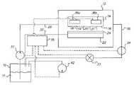
- FIG. 1depicts a schematic of the fluid system of the print station.
- FIG. 2depicts a detailed cross section of the orifice place used in the ink jet print station.
- FIG. 3depicts a block diagram of the method.
- the embodied methods and systemswere devised because ink jet printers with small orifice printheads produce jets that become tangled. Tangled jets cause the jets to short the charge device of the typical ink jet printhead. Shorted charge devices cause printhead errors and even a printhead shutdown.
- the embodied methods and systemswere devised to prevent shorts in the charge device, typically the charge plate, by establishing detangled jets of a jet array of an orifice structure.
- the present methods and systemsare for high resolution printheads with many small diameter orifices that create high quality images.
- the methods and systemspermit a printhead operation with higher concentrations of ink that generally provide an improved quality of image.
- the embodied methods and systemsextend the operating range of small diameter orifice printheads to allow for fluids with higher viscosity than known in the current art.
- the ability to allow higher viscosity fluids to operate through the printheadenables greater versatility of the printhead and more advanced applications.
- the methods and systemspermit even smaller holes to be used successfully on an orifice structure to result in even higher quality process images with more grey levels than other types of printheads with larger orifices.
- the embodied methods and systemsreduce labor time, avoid the need for operator intervention, and enable the systems to be more user friendly by permitting the use of a common state table for different viscosity inks.
- FIG. 1depicts a schematic of the improved print station used with the embodied methods.
- the print stationincludes a reservoir 10 for holding fluid 11 , such as ink jet ink.
- the reservoiris adapted to contain between 0.1 liters and 6 liters of fluid.
- the fluidcan be a cleaning fluid, a dye based ink, a pigment based ink, a water based ink, an oil based ink, or a solvent based ink or combinations of these inks and fluids.
- Water-based inks, such as a FD 1007 black ink,are readily available from Kodak Versamark of Dayton, Ohio.
- the printhead 12includes a drop generator 14 and an orifice structure 16 connected to the drop generator.
- the orifice structurehas numerous orifices for forming numerous jets 18 , 19 , 20 , and 21 .
- FIG. 1depicts only four jets, many more are typically used.
- the orifice structure 16can include more than 240 jets per inch.
- the orifice structure 16can have orifices that have a diameter ranging between 1 mil and 0.4 mils with a preferred range of less than 1 mil. Alternative embodiments have diameters between 0.7 mils and 0.4 mils, preferably less than 0.58 mils.
- Each orifice structurecan include an electroformed orifice structure with one or more sharp edges 38 , as depicted in more detail in FIG. 2 . The sharp edges 38 are located on the drop generator side 40 of the orifice structure.
- FIG. 2depicts the meniscus 23 of the jet 18 .
- the printhead 12includes a catcher 22 disposed in a spaced apart relationship from the drop generator 14 .
- a charge device 24is secured to the catcher for extending a charge to some of the droplets emanating from the jets 18 , 19 , 20 , and 21 .
- the fluid supply systemincludes a fluid supply line 28 connected between the drop generator 14 and the reservoir 10 .
- a return line 30connects to the drop generator 14 and the reservoir 10 .
- a catcher return line 32is connected between the catcher 22 and the reservoir 10 .
- the fluid supply line, the catcher return line and the return linemay all be a flexible line adapted to support pressures ranging between 10 psi and 200 psi without clogging or exploding.
- the return line and catcher return linestypically have outer diameters of about 0.375 inches.
- a controllable valve 33is located in the return line 30 .
- the controllable valve 33is adapted to open and close the return line. Examples of usable controllable valves 33 include two-way controllable valves that can be electrically controlled or otherwise controlled.
- a solenoid valvesis a preferred controllable valve.
- a pressure transducer 34is located in the return line 30 between the drop generator 14 and the controllable valve 33 .
- the printhead 12has a controller 35 that operates the controllable valve 33 in the fluid supply system.
- the controller 35can be an electronic controller with a central processing unit (CPU).
- the electronic controlleris adapted to control a fluid pump 37 , which can be an ink pump, any of the listed plurality of valves, or a vacuum pump 42 in the print station.
- the vacuum pumpis connected to the reservoir enabling the reservoir to provide a reduced pressure to the catcher return line and the return line.
- actuators 36 a and 36 bwhich can be piezoelectric actuators, are connected to the drop generator 14 and the controller 35 .
- the actuators 36 a and 36 bare adapted to vibrate the drop generator that in turn vibrates the orifice structure.
- the actuators 36 a and 36 bvibrate the drop generator at a rate between 50 kHz and 200 kHz.
- a fluid pump 37connects to the fluid supply line and is operated by the controller 35 .
- the fluid pump 37is adapted to raise the pressure on the drop generator 14 to at least an operating pressure of the printhead and to lower the pressure on the drop generator to a minimal pressure thereby preventing entanglement of the jets.
- the pump 37variably pumps the fluid at a pressure to collapse and expand, cyclically expanding and contracting the meniscus 23 of the jets projecting from the orifices, to maintain free flowing detangled jets.
- the pressure on the printheadis cycled between one and ten times, more preferably between three and eight times using an abrupt, non-gradual change in pressure to prevent jet tangling.
- Each cyclealternates between an operating pressure and a pressure lower than the operating pressure. The multiple cycling of the pressure ensures the jets maintain a free flowing and de-tangled orientation.
- Vacuum pump 42is connected to the reservoir. By including a vacuum pump 42 , the reservoir is able to provide a reduced pressure to the catcher return line and the return line.
- FIG. 3depicts a block diagram of a method for establishing detangled jets in an ink jet print station.
- the first embodiment of the methodbegins by inputting values from a state table to a controller for a print station (Step 100 ).
- the values input from the state tableinclude at least two states, the operating pressure for the drop generator and a pressure lower than the operating pressure.
- the print stationis depicted in FIG. 1 .
- the next stepinvolves sensing a pressure at the drop generator and transmitting the sensed pressure to the controller (Step 102 ).
- Step 104the sensed pressure is compared to the values input from the state table (Step 104 ) and if the sensed pressure is different from the input value of the state table, a signal is transmitted to the fluid pump to adjust the pressure of the fluid supply line to meet the value from the state table.
- controllercycles the drop generator pressure using abrupt, non gradual changes in pressure, wherein each cycle alternates between an operating pressure and a pressure lower than the operating pressure of the printhead to insure the jets maintain a free flowing, detangled orientation, as defined by the sequence of states in the state table.
- This cyclingcan be between one and ten cycles.
- a preferred examplehas the pressure of the drop generator cycling six cycles between 20 psi and 35 psi per cycle.
- Table 1depicts a representation of a state table from which values can be input to a controller according to the method.
- a “cycle”is viewed as the change from the high pressure to the low pressure and then back to the high pressure again.
- the embodied methodenables production of images with high resolutions of at least 300 dpi with between one grey level and five grey levels.
- the methodincludes vibrating the drop generator with actuators at a frequency ranging between 50 kHz and 200 kHz.
- the methodcan further include using the vacuum pump or another device to form a negative pressure on the reservoir to return ink from the printhead to the reservoir through the catcher return line and the return line with less energy usage.
- PARTS LIST 10reservoir 11. fluid 12. printhead 14. drop generator 16. orifice structure 18. jet 19. jet 20. jet 21. jet 22. catcher 23. meniscus 24. charge device 28. fluid supply line 30. return line 32. catcher return line 33. controllable valve 34 pressure transducer 35. controller 36a. piezoelectric actuator 36b. piezoelectric actuator 37. fluid pump 38. sharp edge 40. drop generator entrance side 42. vacuum pump 100. step - inputting values from a state table to a controller for a print station 101. step - sensing a pressure at the printhead and to transmit the sensed pressure to the controller 103. step - comparing sensed pressure to the values input from the state table 104. step - transmitting a signal to the pump to adjust the pressure of the fluid supply line to meet the value from the state table 106. step - cycling the pressure of the fluid supply line between three and eight cycles using an abrupt, non-gradual change in pressure
Landscapes
- Ink Jet (AREA)
- Particle Formation And Scattering Control In Inkjet Printers (AREA)
Abstract
Description
| TABLE 1 | ||||
| Pressure | ||||
| at | Vacuum | |||
| transducer, | at reservoir, | |||
| 34 | 10 | % of full | Controllable | Time |
| Psi | in Hg | output | Valve, 33 | Sec |
| 2 | 12 | 30 | 10 | ||
| 20 | 12 | 30 | Close | 6 | |
| 20 | 12 | Close | 10 | ||
| 35 | 12 | 0 | 10 | ||
| 20 | 12 | Close | 10 | ||
| 35 | 12 | Close | 10 | ||
| 20 | 12 | 0 | 10 | ||
| 35 | 12 | 0 | Close | 5 | |
| 10. | |
| 11. | |
| 12. | |
| 14. | |
| 16. | |
| 18. | jet |
| 19. | jet |
| 20. | jet |
| 21. | |
| 22. | |
| 23. | |
| 24. | |
| 28. | |
| 30. | return |
| 32. | |
| 33. | |
| 34 | |
| 35. | |
| 36a. | |
| 36b. | |
| 37. | |
| 38. | |
| 40. | drop |
| 42. | |
| 100. | step - inputting values from a state table to a controller for a print |
| station | |
| 101. | step - sensing a pressure at the printhead and to transmit the sensed |
| pressure to the controller | |
| 103. | step - comparing sensed pressure to the values input from the state |
| table | |
| 104. | step - transmitting a signal to the pump to adjust the pressure of the |
| fluid supply line to meet the value from the state table | |
| 106. | step - cycling the pressure of the fluid supply line between three |
| and eight cycles using an abrupt, non-gradual change in pressure | |
Claims (6)
Priority Applications (1)
| Application Number | Priority Date | Filing Date | Title |
|---|---|---|---|
| US11/673,695US7370951B2 (en) | 2004-05-05 | 2007-02-12 | Method for establishing jets for an ink jet printhead |
Applications Claiming Priority (2)
| Application Number | Priority Date | Filing Date | Title |
|---|---|---|---|
| US10/839,466US7207665B2 (en) | 2004-05-05 | 2004-05-05 | Method for establishing jets for an ink jet printhead |
| US11/673,695US7370951B2 (en) | 2004-05-05 | 2007-02-12 | Method for establishing jets for an ink jet printhead |
Related Parent Applications (1)
| Application Number | Title | Priority Date | Filing Date |
|---|---|---|---|
| US10/839,466DivisionUS7207665B2 (en) | 2004-05-05 | 2004-05-05 | Method for establishing jets for an ink jet printhead |
Publications (2)
| Publication Number | Publication Date |
|---|---|
| US20070126829A1 US20070126829A1 (en) | 2007-06-07 |
| US7370951B2true US7370951B2 (en) | 2008-05-13 |
Family
ID=35239059
Family Applications (2)
| Application Number | Title | Priority Date | Filing Date |
|---|---|---|---|
| US10/839,466Expired - LifetimeUS7207665B2 (en) | 2004-05-05 | 2004-05-05 | Method for establishing jets for an ink jet printhead |
| US11/673,695Expired - LifetimeUS7370951B2 (en) | 2004-05-05 | 2007-02-12 | Method for establishing jets for an ink jet printhead |
Family Applications Before (1)
| Application Number | Title | Priority Date | Filing Date |
|---|---|---|---|
| US10/839,466Expired - LifetimeUS7207665B2 (en) | 2004-05-05 | 2004-05-05 | Method for establishing jets for an ink jet printhead |
Country Status (1)
| Country | Link |
|---|---|
| US (2) | US7207665B2 (en) |
Families Citing this family (1)
| Publication number | Priority date | Publication date | Assignee | Title |
|---|---|---|---|---|
| CN110281656A (en)* | 2019-06-21 | 2019-09-27 | 佛山华派机械科技有限公司 | A kind of circulation ink system and ink road round-robin method for ink-jet printer |
Citations (7)
| Publication number | Priority date | Publication date | Assignee | Title |
|---|---|---|---|---|
| US4314254A (en) | 1980-06-06 | 1982-02-02 | Tamayo Abel C | Insulator for foldable elements of dipole TV antennas |
| US5408738A (en) | 1990-08-16 | 1995-04-25 | Hewlett-Packard Company | Method of making a nozzle member including ink flow channels |
| US5682191A (en) | 1994-01-24 | 1997-10-28 | Iris Graphics Inc. | Ink jet printing apparatus having modular components |
| US20010017642A1 (en) | 1997-07-28 | 2001-08-30 | Yoshihiro Shigemura | Ink jet recording apparatus provided with an improved ink supply route |
| US6299271B1 (en) | 1998-03-31 | 2001-10-09 | Brother Kogyo Kabushiki Kaisha | Ink droplet ejection apparatus and ink jet recorder |
| US6722752B2 (en) | 2002-09-04 | 2004-04-20 | Hewlett-Packard Development Company, L.P. | Pen maintenance system and method for operating same |
| US20050057627A1 (en)* | 2003-08-28 | 2005-03-17 | International Business Machine Corporation | Ink replenishment system and method for a continuous flow ink jet printer |
Family Cites Families (1)
| Publication number | Priority date | Publication date | Assignee | Title |
|---|---|---|---|---|
| US4314264A (en)* | 1980-08-15 | 1982-02-02 | The Mead Corporation | Ink supply system for an ink jet printer |
- 2004
- 2004-05-05USUS10/839,466patent/US7207665B2/ennot_activeExpired - Lifetime
- 2007
- 2007-02-12USUS11/673,695patent/US7370951B2/ennot_activeExpired - Lifetime
Patent Citations (7)
| Publication number | Priority date | Publication date | Assignee | Title |
|---|---|---|---|---|
| US4314254A (en) | 1980-06-06 | 1982-02-02 | Tamayo Abel C | Insulator for foldable elements of dipole TV antennas |
| US5408738A (en) | 1990-08-16 | 1995-04-25 | Hewlett-Packard Company | Method of making a nozzle member including ink flow channels |
| US5682191A (en) | 1994-01-24 | 1997-10-28 | Iris Graphics Inc. | Ink jet printing apparatus having modular components |
| US20010017642A1 (en) | 1997-07-28 | 2001-08-30 | Yoshihiro Shigemura | Ink jet recording apparatus provided with an improved ink supply route |
| US6299271B1 (en) | 1998-03-31 | 2001-10-09 | Brother Kogyo Kabushiki Kaisha | Ink droplet ejection apparatus and ink jet recorder |
| US6722752B2 (en) | 2002-09-04 | 2004-04-20 | Hewlett-Packard Development Company, L.P. | Pen maintenance system and method for operating same |
| US20050057627A1 (en)* | 2003-08-28 | 2005-03-17 | International Business Machine Corporation | Ink replenishment system and method for a continuous flow ink jet printer |
Also Published As
| Publication number | Publication date |
|---|---|
| US20050248630A1 (en) | 2005-11-10 |
| US7207665B2 (en) | 2007-04-24 |
| US20070126829A1 (en) | 2007-06-07 |
Similar Documents
| Publication | Publication Date | Title |
|---|---|---|
| US20120306954A1 (en) | Driving device for liquid discharging head, liquid discharging apparatus, and ink jet recording apparatus | |
| US6561622B1 (en) | Ink-jet recording apparatus | |
| US9849669B2 (en) | Recording method and recording apparatus | |
| US7513586B2 (en) | Waveform signal driven liquid ejection apparatus and image forming apparatus | |
| US11135846B2 (en) | Nozzle geometry for printheads | |
| CN107073953A (en) | fluid ejection equipment | |
| JP2018202713A (en) | Large format printer | |
| CN102785477A (en) | Liquid ejection apparatus and ejection control method for same, and inkjet apparatus | |
| JP2016049690A (en) | Liquid discharge device, control method of the same and control program of the same | |
| JP2017113965A (en) | Liquid ejection apparatus and liquid ejection method | |
| US20030146947A1 (en) | Ink-jet printing apparatus | |
| JP2017128113A (en) | Liquid ejecting apparatus, inkjet system, and flushing method | |
| US7370951B2 (en) | Method for establishing jets for an ink jet printhead | |
| US12059895B2 (en) | Liquid discharging head | |
| US7588308B2 (en) | Liquid ejection apparatus and air bubble determination method | |
| JP2008238469A (en) | Liquid discharge head, liquid discharge apparatus, and liquid discharge method | |
| CN101992595B (en) | Drive waveform for optimization of drop size and drop position | |
| US7478898B2 (en) | Recording head for inkjet recording device | |
| US20220305777A1 (en) | Driving waveform determining method, liquid ejecting apparatus, and non-transitory computer-readable storage medium storing computer program | |
| US9573381B2 (en) | Printing apparatus and bubble exhaust method therefor | |
| CN101111384B (en) | Printheads and systems employing printheads | |
| JP2021169190A (en) | Liquid injection device | |
| JP5549150B2 (en) | DRIVE SIGNAL GENERATION DEVICE, LIQUID DISCHARGE DEVICE, AND DRIVE SIGNAL GENERATION METHOD | |
| US20120056924A1 (en) | Fluid ejecting apparatus and fluid ejecting method | |
| US20250091353A1 (en) | Liquid jet head, liquid jet recording apparatus, and method of controlling liquid jet head |
Legal Events
| Date | Code | Title | Description |
|---|---|---|---|
| FEPP | Fee payment procedure | Free format text:PAYOR NUMBER ASSIGNED (ORIGINAL EVENT CODE: ASPN); ENTITY STATUS OF PATENT OWNER: LARGE ENTITY | |
| STCF | Information on status: patent grant | Free format text:PATENTED CASE | |
| FPAY | Fee payment | Year of fee payment:4 | |
| AS | Assignment | Owner name:CITICORP NORTH AMERICA, INC., AS AGENT, NEW YORK Free format text:SECURITY INTEREST;ASSIGNORS:EASTMAN KODAK COMPANY;PAKON, INC.;REEL/FRAME:028201/0420 Effective date:20120215 | |
| AS | Assignment | Owner name:WILMINGTON TRUST, NATIONAL ASSOCIATION, AS AGENT, Free format text:PATENT SECURITY AGREEMENT;ASSIGNORS:EASTMAN KODAK COMPANY;PAKON, INC.;REEL/FRAME:030122/0235 Effective date:20130322 Owner name:WILMINGTON TRUST, NATIONAL ASSOCIATION, AS AGENT, MINNESOTA Free format text:PATENT SECURITY AGREEMENT;ASSIGNORS:EASTMAN KODAK COMPANY;PAKON, INC.;REEL/FRAME:030122/0235 Effective date:20130322 | |
| AS | Assignment | Owner name:BANK OF AMERICA N.A., AS AGENT, MASSACHUSETTS Free format text:INTELLECTUAL PROPERTY SECURITY AGREEMENT (ABL);ASSIGNORS:EASTMAN KODAK COMPANY;FAR EAST DEVELOPMENT LTD.;FPC INC.;AND OTHERS;REEL/FRAME:031162/0117 Effective date:20130903 Owner name:JPMORGAN CHASE BANK, N.A., AS ADMINISTRATIVE, DELAWARE Free format text:INTELLECTUAL PROPERTY SECURITY AGREEMENT (FIRST LIEN);ASSIGNORS:EASTMAN KODAK COMPANY;FAR EAST DEVELOPMENT LTD.;FPC INC.;AND OTHERS;REEL/FRAME:031158/0001 Effective date:20130903 Owner name:BARCLAYS BANK PLC, AS ADMINISTRATIVE AGENT, NEW YORK Free format text:INTELLECTUAL PROPERTY SECURITY AGREEMENT (SECOND LIEN);ASSIGNORS:EASTMAN KODAK COMPANY;FAR EAST DEVELOPMENT LTD.;FPC INC.;AND OTHERS;REEL/FRAME:031159/0001 Effective date:20130903 Owner name:BARCLAYS BANK PLC, AS ADMINISTRATIVE AGENT, NEW YO Free format text:INTELLECTUAL PROPERTY SECURITY AGREEMENT (SECOND LIEN);ASSIGNORS:EASTMAN KODAK COMPANY;FAR EAST DEVELOPMENT LTD.;FPC INC.;AND OTHERS;REEL/FRAME:031159/0001 Effective date:20130903 Owner name:EASTMAN KODAK COMPANY, NEW YORK Free format text:RELEASE OF SECURITY INTEREST IN PATENTS;ASSIGNORS:CITICORP NORTH AMERICA, INC., AS SENIOR DIP AGENT;WILMINGTON TRUST, NATIONAL ASSOCIATION, AS JUNIOR DIP AGENT;REEL/FRAME:031157/0451 Effective date:20130903 Owner name:PAKON, INC., NEW YORK Free format text:RELEASE OF SECURITY INTEREST IN PATENTS;ASSIGNORS:CITICORP NORTH AMERICA, INC., AS SENIOR DIP AGENT;WILMINGTON TRUST, NATIONAL ASSOCIATION, AS JUNIOR DIP AGENT;REEL/FRAME:031157/0451 Effective date:20130903 Owner name:JPMORGAN CHASE BANK, N.A., AS ADMINISTRATIVE, DELA Free format text:INTELLECTUAL PROPERTY SECURITY AGREEMENT (FIRST LIEN);ASSIGNORS:EASTMAN KODAK COMPANY;FAR EAST DEVELOPMENT LTD.;FPC INC.;AND OTHERS;REEL/FRAME:031158/0001 Effective date:20130903 | |
| FPAY | Fee payment | Year of fee payment:8 | |
| AS | Assignment | Owner name:CREO MANUFACTURING AMERICA LLC, NEW YORK Free format text:RELEASE BY SECURED PARTY;ASSIGNOR:JP MORGAN CHASE BANK, N.A., AS ADMINISTRATIVE AGENT;REEL/FRAME:049814/0001 Effective date:20190617 Owner name:PAKON, INC., NEW YORK Free format text:RELEASE BY SECURED PARTY;ASSIGNOR:JP MORGAN CHASE BANK, N.A., AS ADMINISTRATIVE AGENT;REEL/FRAME:049814/0001 Effective date:20190617 Owner name:QUALEX, INC., NEW YORK Free format text:RELEASE BY SECURED PARTY;ASSIGNOR:JP MORGAN CHASE BANK, N.A., AS ADMINISTRATIVE AGENT;REEL/FRAME:049814/0001 Effective date:20190617 Owner name:KODAK AVIATION LEASING LLC, NEW YORK Free format text:RELEASE BY SECURED PARTY;ASSIGNOR:JP MORGAN CHASE BANK, N.A., AS ADMINISTRATIVE AGENT;REEL/FRAME:049814/0001 Effective date:20190617 Owner name:KODAK IMAGING NETWORK, INC., NEW YORK Free format text:RELEASE BY SECURED PARTY;ASSIGNOR:JP MORGAN CHASE BANK, N.A., AS ADMINISTRATIVE AGENT;REEL/FRAME:049814/0001 Effective date:20190617 Owner name:LASER PACIFIC MEDIA CORPORATION, NEW YORK Free format text:RELEASE BY SECURED PARTY;ASSIGNOR:JP MORGAN CHASE BANK, N.A., AS ADMINISTRATIVE AGENT;REEL/FRAME:049814/0001 Effective date:20190617 Owner name:FAR EAST DEVELOPMENT LTD., NEW YORK Free format text:RELEASE BY SECURED PARTY;ASSIGNOR:JP MORGAN CHASE BANK, N.A., AS ADMINISTRATIVE AGENT;REEL/FRAME:049814/0001 Effective date:20190617 Owner name:KODAK PHILIPPINES, LTD., NEW YORK Free format text:RELEASE BY SECURED PARTY;ASSIGNOR:JP MORGAN CHASE BANK, N.A., AS ADMINISTRATIVE AGENT;REEL/FRAME:049814/0001 Effective date:20190617 Owner name:KODAK (NEAR EAST), INC., NEW YORK Free format text:RELEASE BY SECURED PARTY;ASSIGNOR:JP MORGAN CHASE BANK, N.A., AS ADMINISTRATIVE AGENT;REEL/FRAME:049814/0001 Effective date:20190617 Owner name:NPEC, INC., NEW YORK Free format text:RELEASE BY SECURED PARTY;ASSIGNOR:JP MORGAN CHASE BANK, N.A., AS ADMINISTRATIVE AGENT;REEL/FRAME:049814/0001 Effective date:20190617 Owner name:KODAK AMERICAS, LTD., NEW YORK Free format text:RELEASE BY SECURED PARTY;ASSIGNOR:JP MORGAN CHASE BANK, N.A., AS ADMINISTRATIVE AGENT;REEL/FRAME:049814/0001 Effective date:20190617 Owner name:FPC, INC., NEW YORK Free format text:RELEASE BY SECURED PARTY;ASSIGNOR:JP MORGAN CHASE BANK, N.A., AS ADMINISTRATIVE AGENT;REEL/FRAME:049814/0001 Effective date:20190617 Owner name:KODAK REALTY, INC., NEW YORK Free format text:RELEASE BY SECURED PARTY;ASSIGNOR:JP MORGAN CHASE BANK, N.A., AS ADMINISTRATIVE AGENT;REEL/FRAME:049814/0001 Effective date:20190617 Owner name:KODAK PORTUGUESA LIMITED, NEW YORK Free format text:RELEASE BY SECURED PARTY;ASSIGNOR:JP MORGAN CHASE BANK, N.A., AS ADMINISTRATIVE AGENT;REEL/FRAME:049814/0001 Effective date:20190617 Owner name:EASTMAN KODAK COMPANY, NEW YORK Free format text:RELEASE BY SECURED PARTY;ASSIGNOR:JP MORGAN CHASE BANK, N.A., AS ADMINISTRATIVE AGENT;REEL/FRAME:049814/0001 Effective date:20190617 | |
| MAFP | Maintenance fee payment | Free format text:PAYMENT OF MAINTENANCE FEE, 12TH YEAR, LARGE ENTITY (ORIGINAL EVENT CODE: M1553); ENTITY STATUS OF PATENT OWNER: LARGE ENTITY Year of fee payment:12 | |
| AS | Assignment | Owner name:KODAK (NEAR EAST) INC., NEW YORK Free format text:RELEASE BY SECURED PARTY;ASSIGNOR:BARCLAYS BANK PLC;REEL/FRAME:052773/0001 Effective date:20170202 Owner name:NPEC INC., NEW YORK Free format text:RELEASE BY SECURED PARTY;ASSIGNOR:BARCLAYS BANK PLC;REEL/FRAME:052773/0001 Effective date:20170202 Owner name:KODAK REALTY INC., NEW YORK Free format text:RELEASE BY SECURED PARTY;ASSIGNOR:BARCLAYS BANK PLC;REEL/FRAME:052773/0001 Effective date:20170202 Owner name:KODAK AMERICAS LTD., NEW YORK Free format text:RELEASE BY SECURED PARTY;ASSIGNOR:BARCLAYS BANK PLC;REEL/FRAME:052773/0001 Effective date:20170202 Owner name:FAR EAST DEVELOPMENT LTD., NEW YORK Free format text:RELEASE BY SECURED PARTY;ASSIGNOR:BARCLAYS BANK PLC;REEL/FRAME:052773/0001 Effective date:20170202 Owner name:FPC INC., NEW YORK Free format text:RELEASE BY SECURED PARTY;ASSIGNOR:BARCLAYS BANK PLC;REEL/FRAME:052773/0001 Effective date:20170202 Owner name:LASER PACIFIC MEDIA CORPORATION, NEW YORK Free format text:RELEASE BY SECURED PARTY;ASSIGNOR:BARCLAYS BANK PLC;REEL/FRAME:052773/0001 Effective date:20170202 Owner name:QUALEX INC., NEW YORK Free format text:RELEASE BY SECURED PARTY;ASSIGNOR:BARCLAYS BANK PLC;REEL/FRAME:052773/0001 Effective date:20170202 Owner name:KODAK PHILIPPINES LTD., NEW YORK Free format text:RELEASE BY SECURED PARTY;ASSIGNOR:BARCLAYS BANK PLC;REEL/FRAME:052773/0001 Effective date:20170202 Owner name:EASTMAN KODAK COMPANY, NEW YORK Free format text:RELEASE BY SECURED PARTY;ASSIGNOR:BARCLAYS BANK PLC;REEL/FRAME:052773/0001 Effective date:20170202 | |
| AS | Assignment | Owner name:ALTER DOMUS (US) LLC, ILLINOIS Free format text:INTELLECTUAL PROPERTY SECURITY AGREEMENT;ASSIGNOR:EASTMAN KODAK COMPANY;REEL/FRAME:056733/0681 Effective date:20210226 Owner name:ALTER DOMUS (US) LLC, ILLINOIS Free format text:INTELLECTUAL PROPERTY SECURITY AGREEMENT;ASSIGNOR:EASTMAN KODAK COMPANY;REEL/FRAME:056734/0001 Effective date:20210226 Owner name:ALTER DOMUS (US) LLC, ILLINOIS Free format text:INTELLECTUAL PROPERTY SECURITY AGREEMENT;ASSIGNOR:EASTMAN KODAK COMPANY;REEL/FRAME:056734/0233 Effective date:20210226 Owner name:BANK OF AMERICA, N.A., AS AGENT, MASSACHUSETTS Free format text:NOTICE OF SECURITY INTERESTS;ASSIGNOR:EASTMAN KODAK COMPANY;REEL/FRAME:056984/0001 Effective date:20210226 |