US7370883B2 - Three dimensional occupant position sensor - Google Patents
Three dimensional occupant position sensorDownload PDFInfo
- Publication number
- US7370883B2 US7370883B2US10/161,021US16102102AUS7370883B2US 7370883 B2US7370883 B2US 7370883B2US 16102102 AUS16102102 AUS 16102102AUS 7370883 B2US7370883 B2US 7370883B2
- Authority
- US
- United States
- Prior art keywords
- occupant
- determining
- points
- dimension
- signal
- Prior art date
- Legal status (The legal status is an assumption and is not a legal conclusion. Google has not performed a legal analysis and makes no representation as to the accuracy of the status listed.)
- Expired - Fee Related, expires
Links
- 238000000034methodMethods0.000claimsabstractdescription17
- 238000004458analytical methodMethods0.000abstractdescription3
- 230000006870functionEffects0.000description13
- 238000003491arrayMethods0.000description6
- 238000005311autocorrelation functionMethods0.000description6
- 238000004364calculation methodMethods0.000description5
- 230000005684electric fieldEffects0.000description5
- 230000014509gene expressionEffects0.000description4
- 101100129500Caenorhabditis elegans max-2 geneProteins0.000description3
- 230000004044responseEffects0.000description3
- RYGMFSIKBFXOCR-UHFFFAOYSA-NCopperChemical compound[Cu]RYGMFSIKBFXOCR-UHFFFAOYSA-N0.000description2
- 108010076504Protein Sorting SignalsProteins0.000description2
- 230000003044adaptive effectEffects0.000description2
- 229910052802copperInorganic materials0.000description2
- 239000010949copperSubstances0.000description2
- 210000003127kneeAnatomy0.000description2
- 238000005259measurementMethods0.000description2
- 238000005070samplingMethods0.000description2
- 238000001228spectrumMethods0.000description2
- 208000027418Wounds and injuryDiseases0.000description1
- 230000003321amplificationEffects0.000description1
- 238000013459approachMethods0.000description1
- 235000019504cigarettesNutrition0.000description1
- 239000004020conductorSubstances0.000description1
- 238000013527convolutional neural networkMethods0.000description1
- 230000006378damageEffects0.000description1
- 238000000354decomposition reactionMethods0.000description1
- 230000003247decreasing effectEffects0.000description1
- 238000006073displacement reactionMethods0.000description1
- 230000000694effectsEffects0.000description1
- 238000011156evaluationMethods0.000description1
- 238000002474experimental methodMethods0.000description1
- 208000014674injuryDiseases0.000description1
- 239000011159matrix materialSubstances0.000description1
- 230000000116mitigating effectEffects0.000description1
- 238000003199nucleic acid amplification methodMethods0.000description1
- 230000003287optical effectEffects0.000description1
Images


Classifications
- B—PERFORMING OPERATIONS; TRANSPORTING
- B60—VEHICLES IN GENERAL
- B60R—VEHICLES, VEHICLE FITTINGS, OR VEHICLE PARTS, NOT OTHERWISE PROVIDED FOR
- B60R21/00—Arrangements or fittings on vehicles for protecting or preventing injuries to occupants or pedestrians in case of accidents or other traffic risks
- B60R21/01—Electrical circuits for triggering passive safety arrangements, e.g. airbags, safety belt tighteners, in case of vehicle accidents or impending vehicle accidents
- B60R21/015—Electrical circuits for triggering passive safety arrangements, e.g. airbags, safety belt tighteners, in case of vehicle accidents or impending vehicle accidents including means for detecting the presence or position of passengers, passenger seats or child seats, and the related safety parameters therefor, e.g. speed or timing of airbag inflation in relation to occupant position or seat belt use
- B60R21/01512—Passenger detection systems
- B60R21/01542—Passenger detection systems detecting passenger motion
- B—PERFORMING OPERATIONS; TRANSPORTING
- B60—VEHICLES IN GENERAL
- B60R—VEHICLES, VEHICLE FITTINGS, OR VEHICLE PARTS, NOT OTHERWISE PROVIDED FOR
- B60R21/00—Arrangements or fittings on vehicles for protecting or preventing injuries to occupants or pedestrians in case of accidents or other traffic risks
- B60R21/01—Electrical circuits for triggering passive safety arrangements, e.g. airbags, safety belt tighteners, in case of vehicle accidents or impending vehicle accidents
- B60R21/015—Electrical circuits for triggering passive safety arrangements, e.g. airbags, safety belt tighteners, in case of vehicle accidents or impending vehicle accidents including means for detecting the presence or position of passengers, passenger seats or child seats, and the related safety parameters therefor, e.g. speed or timing of airbag inflation in relation to occupant position or seat belt use
- B60R21/01512—Passenger detection systems
- B60R21/0153—Passenger detection systems using field detection presence sensors
- B60R21/01532—Passenger detection systems using field detection presence sensors using electric or capacitive field sensors
- B—PERFORMING OPERATIONS; TRANSPORTING
- B60—VEHICLES IN GENERAL
- B60R—VEHICLES, VEHICLE FITTINGS, OR VEHICLE PARTS, NOT OTHERWISE PROVIDED FOR
- B60R21/00—Arrangements or fittings on vehicles for protecting or preventing injuries to occupants or pedestrians in case of accidents or other traffic risks
- B60R21/01—Electrical circuits for triggering passive safety arrangements, e.g. airbags, safety belt tighteners, in case of vehicle accidents or impending vehicle accidents
- B60R21/015—Electrical circuits for triggering passive safety arrangements, e.g. airbags, safety belt tighteners, in case of vehicle accidents or impending vehicle accidents including means for detecting the presence or position of passengers, passenger seats or child seats, and the related safety parameters therefor, e.g. speed or timing of airbag inflation in relation to occupant position or seat belt use
- B60R21/01512—Passenger detection systems
- B60R21/0153—Passenger detection systems using field detection presence sensors
- B60R21/01534—Passenger detection systems using field detection presence sensors using electromagneticwaves, e.g. infrared
Definitions
- the present inventionrelates to vehicle occupant safety systems, and more particularly, to a vehicle occupant proximity sensor for use with a vehicle occupant safety system.
- a vehiclemay contain automatic safety restraint actuators such as front and side air bags, seat belt pretensioners, and deployable knee bolsters.
- the occupant protection systemmay further include a collision/crash sensor for sensing the occurrence of a vehicle crash and for providing an electrical signal indicative of the crash severity.
- occupant protection systemsinclude an occupant position sensor that senses the position of the occupant with respect to an associated inflatable protection module.
- the occupant position sensor for such a systemcould be an ultrasonic sensor, an infrared sensor, and a capacitive sensor, and/or a weight sensor.
- a controllerwhich is connected to the sensors, controls the inflatable protection module in response to the sensed position of the occupant.
- one or more deployment aspects of the air bagmay be adjusted.
- a protection system with adjustable aspects of deploymentis commonly referred to as an “adaptive” protection system.
- An occupant who is very near the protection moduleis referred to as being within an occupant out-of-position zone. Deploying the air bag for an occupant who is within the occupant out-of-position zone may not enhance protection of the occupant.
- the determination of occupant's positionis an important part of adaptive occupant protection system.
- proximity sensorssuch as ultrasonic sensor, a video sensor, a capacitive sensor, and an infrared sensor.
- Different obstaclessuch as a map, a book, or a newspaper could occlude signals from ultrasonic and video sensors.
- a lighter or cigarettecould blind an infrared sensor.
- This inventionis based on the conductivity of the human body. This phenomenon allows the occupant to be used as a transmitting antenna, determining his/her position within a defined space by measurement of electromagnetic values induced on a set of receivers.
- the present inventionprovides an occupant position sensor utilizing an occupant's conductivity to determine the occupant's height and position by measuring the capacity between the occupant's head and a plurality of roof-mounted sensors (electrodes).
- a transmitting electrodeis mounted in a vehicle seat.
- An arrangement of receiving electrodesis mounted to the ceiling of the vehicle above the occupant's seat.
- the sensorutilizes the human body's conductivity by using the occupant as a transmitter.
- the highest point of an occupant's bodyis considered as source for the electromagnetic waveform.
- the values of the signals induced on each electrodeis measured by the control unit and then processed in order to determine the position and to track the motion of the highest point of an occupant's body.
- the method presented in this inventionprovides the ability to determine a three-dimensional position of the highest point of an occupant's body within the sensing space.
- FIG. 1illustrates the vehicle occupant proximity sensor installed in a vehicle passenger compartment with an occupant safety system.
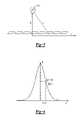
- FIG. 2is a schematic representation illustrating the calculation of the position and height of the occupant.
- FIG. 3is another schematic illustrating the method of calculating the position and height of the occupant.
- FIG. 4is a graph illustrating the linear interpolation between neighboring samples of the autocorrelation function.
- FIG. 5 ais a graph of a source signal.
- FIG. 5 bshows graphs of functions f1(K i ) (line 1), f2(K i ) (line 2), f1(K i ) ⁇ f2(K i ) (line 3) which were calculated for the source signal as illustrated in FIG. 5 a.
- FIG. 6 ais a graph of a source signal in an example when two objects create a resolution element in a signal.
- FIG. 6 bis a graph of the autocorrelation function for the source signal of FIG. 6 b.
- FIG. 6 cis a graph of f1(line 1), f2 (line 2) and f1 ⁇ f2 (line 4) for the source signal for FIG. 6 a.
- FIG. 1illustrates a vehicle occupant proximity sensor 10 for determining the height and position of an occupant 12 in a vehicle seat 14 , and more particularly, for determining the three-dimensional position of the occupant's head 15 .
- the occupant 12 and vehicle seat 14are installed in a vehicle passenger compartment 16 having an occupant safety system, including an automatic safety restraint, such as an airbag 18 .
- an automatic safety restraintsuch as an airbag 18 .
- a steering wheel mounted airbag 18is illustrated as an example, it should also be understood that the present invention is also useful for side airbags, seatbelt pre-tensioners, deployable knee bolsters, and any other automatic safety restraint actuators.
- Crash detector 19such as a crash sensor of any known type, is used to determine the occurrence of a vehicle crash and to determine the crash severity.
- the vehicle occupant proximity sensor 10comprises a transmitting electrode 20 generating an electromagnetic signal and a first array 22 of receiving electrodes 22 a - n perpendicularly intersecting a second array 23 of receiving electrodes 23 a - n .
- the receiving electrodes 22 a - n , 23 a - nreceive the electromagnetic signal generated by the transmitting electrode 20 .
- a control unit 24receives electrical signals from the receiving electrodes 22 a - n , 23 a - n based upon the electromagnetic signal received by the electrodes 22 a - n , 23 a - n .
- the control unit 24may also receive a signal from seat track position sensor 26 indicating the position of the vehicle seat 14 on a vehicle track (not shown) in the passenger compartment 16 .
- the transmitting electrode 20is mounted in the base of vehicle seat 14 .
- the transmitting electrode 20may comprise a coil of wire or a copper sheet and can be made from any conductive material, but preferably comprises a mesh of copper wires approximately one inch apart. Generally, it is preferred to cover a large area of the base of the seat 14 with the transmitting electrode 20 and to wrap the transmitting electrode around the front of the seat. It should be insured that the transmitting electrode is not shorted to ground via the frame of the vehicle.
- a frequency generator 27generates a 10 KHz signal to the transmitting electrode 20 , which is then transmitted as an electromagnetic signal in the passenger compartment 16 .
- the receiving electrode arrays 22 , 23are mounted in the vehicle headliner 28 in the passenger compartment 16 above the occupant 12 .
- the receiving electrodes 22 a - n , 23 a - neach comprise a small conductive surface, preferably a 6.5 cm by 9 cm piece of printed circuit board.
- the receiving electrodes 22 a - n , 23 a - nare connected to the control unit 24 via a multiplexer 29 and amplifier 30 . Again, it must be insured that none of the receiving electrodes 22 a - n , 23 a - n are shorted to ground via the frame.
- the multiplexer 29enables the control unit 24 to sequentially read values from the receiving electrodes 22 a - n , 23 a - n to determine the three dimensional position of the occupant 12 according the method described below.
- Analog-to-digital converters(not shown) would convert the signals from amplifiers 30 to a computer-readable format.
- the control unit 24generally comprises a CPU 31 having memory 32 , for example, RAM, ROM, DVD, CD, a hard drive, or other electronic, optical, magnetic, or any other computer readable medium onto which is stored programs for performing the steps and algorithms described herein.
- the CPU 31is suitably programmed to perform the functions described herein and a person of ordinary skill in the art could program the CPU 31 accordingly and supply any additional hardware not shown but needed to implement the present invention based upon the description herein.
- the control unit 24controls generator 27 to generate a 10 KHz signal to the transmitting electrode 20 .
- the transmitting electrode 20transmits a 10 KHz signal as an electromagnetic wave inside the vehicle passenger compartment 16 .
- the electromagnetic signalpasses through occupant 12 and is received by the receiving electrodes 22 a - n , 23 a - n .
- the signal received by each receiving electrodeis based upon the capacity between it and the transmitting electrode 20 , which in turn will vary depending upon the proximity of the occupant 12 to each receiving electrode 22 a - n , 23 a - n .
- the size, spacing and number of electrodes in each of the receiving electrode arrays 22 , 23may vary for different applications and different vehicles.
- the control unit 24controls multiplexer 29 to sequentially read each of the receiving electrodes 22 a - n , 23 a - n in arrays 22 , 23 . Although performed sequentially, it is performed sufficiently quickly relative to normal motion of a vehicle occupant 12 to provide what is effectively an instantaneous snapshot of sufficient information to determine the height and position of the occupant 12 in the passenger compartment 16 .
- the capacity at each receiving electrode 22 a - n , 23 a - ndepends on the proximity of the occupant 12 to each receiving electrode 22 a - n , 23 a - n . Thus, the highest capacity will be measured at the receiving electrode closest to head 15 of the vehicle occupant 12 .
- the occupantis coupled to the oscillator via the seat-mounted electrode to provide a capacitive connection.
- the electromagnetic waveis transmitted from the highest point of the occupant and is induced on each electrode.
- the value of the signal on each electrodeis a function of the distance between the highest point of the occupant and the electrode (see FIG. 2 ).
- Amplifiers 30send these values to the control unit 24 .
- the values of the signal on each electrodeare processed independently for each row to obtain the x (or y) position coordinates along the row and the perpendicular distance h x (or h y ) to each row.
- 2D coordinates for each roware determined by using signal shape according to the following:
- the electric field at the rowis determined by measuring the electric field induced on the flat electrode.
- the linear size of the electrode and the typical object's sizeare significantly bigger than adequate accuracy. Therefore the determination of an absolute occupant position is solved using the calibration approach.
- both the signal from a typical object, which is used as a calibration signal, and the absolute position of the objectare stored in memory 32 .
- the position of a real objectis determined as displacement of the object signal relative to the calibration signal.
- the electric field of a complex objectis a superposition of point sources of charge, so the presented system is a linear shift-invariant system for the given height. Convolution of a current signal with stored calibration signal is used to determine position along the row.
- Convolution K nis calculated by Fourier transform according to convolution theorem is:
- S nis a signal sample's sequence
- C ncalibration signal sequence
- ⁇ and ⁇ ⁇ 1is a pair of discrete Fourier transforms, defined as:
- the Fast Fourier Transform (FFT) algorithmis used to calculate the discrete Fourier transform.
- the system and method of the present inventionalso determine the height coordinate. Let's call a signal created by a point electric charge, a ‘simple wave.’ Point charge creates an electric field:
- H 2 x 2K ⁇ ( x ) K ⁇ ( 0 ) - K ⁇ ( x ) ( 12 )
- hmay be evaluated not only by using the signal, but also by the signal autocorrelation function.
- This functionrepresents an integral characteristic of the signal and thus is less sensitive to noise.
- this functionis symmetric by its nature and has a maximum exactly at x equal to zero. Thus the problem of an accurate maximum position definition is not a present concern.
- expression (12) for hworks very well. However, one weak dependence was found, h depends on the level of the hardware amplification, which differs for different K(x) parts. For better comprehension we will make the following analysis of K(x) shape.
- H(K)should be a constant and therefore its derivative should be zero.
- FIG. 5 bshows functions f1(K i ) (line 1), f2(K i ) (line 2 ), f1(K i ) ⁇ f2(K i ) (line 3) which were calculated for a source signal as illustrated in FIG. 5 a.
- FIG. 6shows an example when two objects create a resolution element in a signal.
- FIG. 6 ais a source signal
- FIG. 6 bis its autocorrelation function
- FIG. 6 cshows f1(line 1), f2(line 2 ) and f1 ⁇ f2(line 4).
- This algorithminvolves one 16-point FFT, one 64-point FFT, one 32-point FFT and a few vector operations such as multiplication, subtraction and maximum search to determine 2D position for each row.
- the control unit 24monitors the information from the receiving electrode array 22 over time. For example, the position of the head 15 of occupant 12 cannot change instantaneously; it must follow a path from one point to another.
- the control unit 24may additionally take information from the vehicle seat track sensor 26 , which indicates the position of the vehicle seat 14 on a vehicle seat track.
- control unit 24determines whether to deploy the airbag 18 (or other safety restraint device) based upon a crash detected by crash detector 19 and the severity of a crash. For example, if the control unit 24 determines, based upon information from receiving electrode array 22 , that the occupant 12 is too close to airbag 18 , the control unit 24 may determine not to activate airbag 18 in the event of a crash, or the control unit 24 may determine that airbag 18 should be deployed with less force.
- control unit 24determines based upon information from receiving electrode arrays 22 , 23 that occupant is at a distance from airbag 18 in excess of a predetermined threshold, the control unit 24 will cause airbag 18 to deploy, or will cause airbag 18 to deploy with higher force, depending upon the severity of the crash as determined by crash detector 19 .
- the control unit 24also determines the force with which the airbag 18 (or other sarety restraint device) should deploy based upon the height of the occupant 12 .
- information from seat track sensor 26may be utilized with the proximity information to determine whether and/or how airbag 18 should be deployed. For example, if seat track sensor 26 indicates that the vehicle seat 14 is adjusted forward in the vehicle passenger compartment 16 , and the receiving electrode arrays 22 , 23 indicate that the occupant 12 is also forward, the control unit 24 may determine not to deploy airbag 18 in the event of a crash. On the other hand, if the seat track position sensor indicates that the vehicle seat 14 is too far forward, the control unit 24 may decide not to deploy airbag 18 , even though the receiving electrode arrays 22 , 23 indicate that the head 15 of the occupant 12 is sufficiently rearward for deployment. This would occur in the event that the occupant 12 has the vehicle seat 14 reclined significantly.
- control unit 24may determine that if the head 15 of the occupant 12 is sufficiently rearward, the airbag 18 may be deployed in the event of a crash even though the vehicle seat track position sensor 26 indicates that the vehicle seat 14 is too far forward. This would indicate that the occupant 12 again has the vehicle seat 14 reclined significantly and sufficiently that the airbag 18 should be deployed.
- control unit 24utilizing the above and many additional rules for whether to fire airbag 18 , and for a multiple stage airbag 18 , how much force airbag 18 should be deployed.
- the present inventionprovides additional information to the control unit 24 , such that those of ordinary skill in the art could take in this additional information to properly determine whether and with how much force to activate airbag 18 .
Landscapes
- Engineering & Computer Science (AREA)
- Mechanical Engineering (AREA)
- Physics & Mathematics (AREA)
- Electromagnetism (AREA)
- Air Bags (AREA)
Abstract
Description
h2=hx2−y2=hy2−x2 (1)
where Snis a signal sample's sequence, Cn—calibration signal sequence, Ψ and Ψ−1is a pair of discrete Fourier transforms, defined as:
where q is electric charge value, r—is the distance between charge and measurement point, and a—is a constant.
which looks like (8) with H=2h.
0≦K≦K max (13)
which is obtained from (15) and (17), when H=2·h.
Claims (11)
Priority Applications (5)
| Application Number | Priority Date | Filing Date | Title |
|---|---|---|---|
| US10/161,021US7370883B2 (en) | 2002-06-03 | 2002-06-03 | Three dimensional occupant position sensor |
| PCT/CA2003/000834WO2003101785A1 (en) | 2002-06-03 | 2003-06-03 | Three dimensional occupant position sensor |
| AU2003238591AAU2003238591A1 (en) | 2002-06-03 | 2003-06-03 | Three dimensional occupant position sensor |
| EP03732151AEP1509425B1 (en) | 2002-06-03 | 2003-06-03 | Three dimensional occupant position sensor |
| DE60308020TDE60308020T2 (en) | 2002-06-03 | 2003-06-03 | THREE-DIMENSIONAL INSULATED POSITION SENSOR |
Applications Claiming Priority (1)
| Application Number | Priority Date | Filing Date | Title |
|---|---|---|---|
| US10/161,021US7370883B2 (en) | 2002-06-03 | 2002-06-03 | Three dimensional occupant position sensor |
Publications (2)
| Publication Number | Publication Date |
|---|---|
| US20030222440A1 US20030222440A1 (en) | 2003-12-04 |
| US7370883B2true US7370883B2 (en) | 2008-05-13 |
Family
ID=29583331
Family Applications (1)
| Application Number | Title | Priority Date | Filing Date |
|---|---|---|---|
| US10/161,021Expired - Fee RelatedUS7370883B2 (en) | 2002-06-03 | 2002-06-03 | Three dimensional occupant position sensor |
Country Status (5)
| Country | Link |
|---|---|
| US (1) | US7370883B2 (en) |
| EP (1) | EP1509425B1 (en) |
| AU (1) | AU2003238591A1 (en) |
| DE (1) | DE60308020T2 (en) |
| WO (1) | WO2003101785A1 (en) |
Cited By (25)
| Publication number | Priority date | Publication date | Assignee | Title |
|---|---|---|---|---|
| US20080246318A1 (en)* | 2004-03-19 | 2008-10-09 | Hans-Dieter Bothe | Device for Adjusting Seat Components |
| US20090183125A1 (en)* | 2008-01-14 | 2009-07-16 | Prime Sense Ltd. | Three-dimensional user interface |
| US20100241309A1 (en)* | 2009-03-20 | 2010-09-23 | Toyota Motor Engineering & Manufacturing NA (TEMA) | Electronic control system, electronic control unit and associated methodology of adapting a vehicle system based on visually detected vehicle occupant information |
| US20110074916A1 (en)* | 2009-09-29 | 2011-03-31 | Toyota Motor Engin. & Manufact. N.A. (TEMA) | Electronic control system, electronic control unit and associated methodology of adapting 3d panoramic views of vehicle surroundings by predicting driver intent |
| US20110211754A1 (en)* | 2010-03-01 | 2011-09-01 | Primesense Ltd. | Tracking body parts by combined color image and depth processing |
| US20140047381A1 (en)* | 2012-08-10 | 2014-02-13 | Microsoft Corporation | 3d data environment navigation tool |
| US8872762B2 (en) | 2010-12-08 | 2014-10-28 | Primesense Ltd. | Three dimensional user interface cursor control |
| US8881051B2 (en) | 2011-07-05 | 2014-11-04 | Primesense Ltd | Zoom-based gesture user interface |
| US8933876B2 (en) | 2010-12-13 | 2015-01-13 | Apple Inc. | Three dimensional user interface session control |
| US8959013B2 (en) | 2010-09-27 | 2015-02-17 | Apple Inc. | Virtual keyboard for a non-tactile three dimensional user interface |
| US9030498B2 (en) | 2011-08-15 | 2015-05-12 | Apple Inc. | Combining explicit select gestures and timeclick in a non-tactile three dimensional user interface |
| US9035876B2 (en) | 2008-01-14 | 2015-05-19 | Apple Inc. | Three-dimensional user interface session control |
| US9122311B2 (en) | 2011-08-24 | 2015-09-01 | Apple Inc. | Visual feedback for tactile and non-tactile user interfaces |
| US9158375B2 (en) | 2010-07-20 | 2015-10-13 | Apple Inc. | Interactive reality augmentation for natural interaction |
| US9201501B2 (en) | 2010-07-20 | 2015-12-01 | Apple Inc. | Adaptive projector |
| US9218063B2 (en) | 2011-08-24 | 2015-12-22 | Apple Inc. | Sessionless pointing user interface |
| US9229534B2 (en) | 2012-02-28 | 2016-01-05 | Apple Inc. | Asymmetric mapping for tactile and non-tactile user interfaces |
| US9285874B2 (en) | 2011-02-09 | 2016-03-15 | Apple Inc. | Gaze detection in a 3D mapping environment |
| US9377865B2 (en) | 2011-07-05 | 2016-06-28 | Apple Inc. | Zoom-based gesture user interface |
| US9377863B2 (en) | 2012-03-26 | 2016-06-28 | Apple Inc. | Gaze-enhanced virtual touchscreen |
| US9459758B2 (en) | 2011-07-05 | 2016-10-04 | Apple Inc. | Gesture-based interface with enhanced features |
| US9555739B1 (en)* | 2016-01-13 | 2017-01-31 | International Business Machines Corporation | Vehicle safety belt bypass warning system |
| US9919670B2 (en) | 2015-06-17 | 2018-03-20 | Ford Global Technologies, Llc | System and method for occupant height |
| US9931964B2 (en) | 2015-06-17 | 2018-04-03 | Ford Global Technologies, Llc | Occupant weight and height estimation |
| US20190039549A1 (en)* | 2017-08-01 | 2019-02-07 | Ford Global Technologies, Llc | Restraint system |
Families Citing this family (26)
| Publication number | Priority date | Publication date | Assignee | Title |
|---|---|---|---|---|
| US8152198B2 (en)* | 1992-05-05 | 2012-04-10 | Automotive Technologies International, Inc. | Vehicular occupant sensing techniques |
| US20080023946A1 (en)* | 2004-01-30 | 2008-01-31 | Daimlerchrysler Ag | Driver Restraining System in a Motor Vehicle |
| US7457692B2 (en)* | 2004-10-12 | 2008-11-25 | Ford Global Technologies Llc | Occupant classification sensor calibration system |
| US20070154045A1 (en)* | 2005-12-29 | 2007-07-05 | Basir Otman A | Directing a microphone toward a vehicle occupant |
| US20100014711A1 (en)* | 2008-07-16 | 2010-01-21 | Volkswagen Group Of America, Inc. | Method for controlling an illumination in a vehicle interior in dependence on a head pose detected with a 3D sensor |
| US10307104B2 (en) | 2011-07-05 | 2019-06-04 | Saudi Arabian Oil Company | Chair pad system and associated, computer medium and computer-implemented methods for monitoring and improving health and productivity of employees |
| US9844344B2 (en) | 2011-07-05 | 2017-12-19 | Saudi Arabian Oil Company | Systems and method to monitor health of employee when positioned in association with a workstation |
| US9962083B2 (en) | 2011-07-05 | 2018-05-08 | Saudi Arabian Oil Company | Systems, computer medium and computer-implemented methods for monitoring and improving biomechanical health of employees |
| US9526455B2 (en)* | 2011-07-05 | 2016-12-27 | Saudi Arabian Oil Company | Systems, computer medium and computer-implemented methods for monitoring and improving health and productivity of employees |
| US9492120B2 (en) | 2011-07-05 | 2016-11-15 | Saudi Arabian Oil Company | Workstation for monitoring and improving health and productivity of employees |
| US9710788B2 (en) | 2011-07-05 | 2017-07-18 | Saudi Arabian Oil Company | Computer mouse system and associated, computer medium and computer-implemented methods for monitoring and improving health and productivity of employees |
| US10108783B2 (en) | 2011-07-05 | 2018-10-23 | Saudi Arabian Oil Company | Systems, computer medium and computer-implemented methods for monitoring health of employees using mobile devices |
| JP2014525086A (en) | 2011-07-05 | 2014-09-25 | サウジ アラビアン オイル カンパニー | Floor mat system and associated computer media for monitoring and improving employee health and productivity, and computer-implemented methods |
| DE102011118431A1 (en)* | 2011-11-12 | 2013-05-16 | Audi Ag | Method for recognizing mounting of luggage rack at roof rail of vehicle e.g. motor car, involves recognizing mounting of luggage rack based on detected bypass resistance and detected coupling capacitance between detection surfaces |
| US20130304315A1 (en)* | 2012-05-10 | 2013-11-14 | Elesys North America Inc. | Operator recognition system |
| US10052972B2 (en) | 2013-03-26 | 2018-08-21 | Intel Corporation | Vehicular occupancy assessment |
| US9722472B2 (en) | 2013-12-11 | 2017-08-01 | Saudi Arabian Oil Company | Systems, computer medium and computer-implemented methods for harvesting human energy in the workplace |
| US20160117074A1 (en)* | 2014-05-15 | 2016-04-28 | T+Ink, Inc. | Area input device and virtual keyboard |
| US9889311B2 (en) | 2015-12-04 | 2018-02-13 | Saudi Arabian Oil Company | Systems, protective casings for smartphones, and associated methods to enhance use of an automated external defibrillator (AED) device |
| US10475351B2 (en) | 2015-12-04 | 2019-11-12 | Saudi Arabian Oil Company | Systems, computer medium and methods for management training systems |
| US10642955B2 (en) | 2015-12-04 | 2020-05-05 | Saudi Arabian Oil Company | Devices, methods, and computer medium to provide real time 3D visualization bio-feedback |
| US10628770B2 (en) | 2015-12-14 | 2020-04-21 | Saudi Arabian Oil Company | Systems and methods for acquiring and employing resiliency data for leadership development |
| US10824132B2 (en) | 2017-12-07 | 2020-11-03 | Saudi Arabian Oil Company | Intelligent personal protective equipment |
| DE102020204286A1 (en) | 2020-04-02 | 2021-10-07 | Continental Automotive Gmbh | Methods and apparatus for locating a moving subject |
| US12246668B2 (en) | 2022-12-14 | 2025-03-11 | GM Global Technology Operations LLC | Motor vehicle with selective airbag suppression based on occupant position and seatbelt usage |
| US20240198941A1 (en)* | 2022-12-14 | 2024-06-20 | GM Global Technology Operations LLC | Vehicle with occupant trajectory-based airbag suppression |
Citations (35)
| Publication number | Priority date | Publication date | Assignee | Title |
|---|---|---|---|---|
| US3843924A (en) | 1972-09-20 | 1974-10-22 | Farad Ab | Apparatus for determining the coordinates of an object, moveable along at least one coordinate axis |
| US4305074A (en) | 1980-05-12 | 1981-12-08 | The United States Of America As Represented By The Secretary Of The Army | Electromagnetic detection apparatus |
| US4796013A (en)* | 1985-10-18 | 1989-01-03 | Aisin Seiki Kabushiki Kaisha | Capacitive occupancy detector apparatus |
| US5118134A (en) | 1990-02-22 | 1992-06-02 | Robert Bosch Gmbh | Method and apparatus for protecting motor vehicle occupants |
| US5214388A (en) | 1992-05-28 | 1993-05-25 | The United States Of America As Represented By The Administrator Of The National Aeronautics And Space Administration | Phase discriminating capacitive array sensor system |
| US5247261A (en) | 1991-10-09 | 1993-09-21 | The Massachusetts Institute Of Technology | Method and apparatus for electromagnetic non-contact position measurement with respect to one or more axes |
| US5247281A (en) | 1991-07-08 | 1993-09-21 | Societe Anonyme Dite Bertin & Cie | Capacitive phase shift proximity detector |
| US5330226A (en) | 1992-12-04 | 1994-07-19 | Trw Vehicle Safety Systems Inc. | Method and apparatus for detecting an out of position occupant |
| US5439249A (en) | 1993-12-02 | 1995-08-08 | Trw Vehicle Safety Systems Inc. | Vehicle occupant restraint system including occupant position sensor mounted in seat back |
| US5482314A (en)* | 1994-04-12 | 1996-01-09 | Aerojet General Corporation | Automotive occupant sensor system and method of operation by sensor fusion |
| US5691693A (en) | 1995-09-28 | 1997-11-25 | Advanced Safety Concepts, Inc. | Impaired transportation vehicle operator system |
| US5770997A (en) | 1995-06-26 | 1998-06-23 | Alliedsignal Inc. | Vehicle occupant sensing system |
| US5772686A (en) | 1995-04-27 | 1998-06-30 | Caruana; Patrick | Pelvic retroverter |
| US5802479A (en) | 1994-09-23 | 1998-09-01 | Advanced Safety Concepts, Inc. | Motor vehicle occupant sensing systems |
| US5844415A (en) | 1994-02-03 | 1998-12-01 | Massachusetts Institute Of Technology | Method for three-dimensional positions, orientation and mass distribution |
| US5871232A (en)* | 1997-01-17 | 1999-02-16 | Automotive Systems, Laboratory, Inc. | Occupant position sensing system |
| DE19841399A1 (en) | 1997-09-11 | 1999-03-25 | Toyota Motor Co Ltd | Use-status determination arrangement for vehicle seat, e.g. to determine if seat is occupied to control airbag |
| US5948031A (en) | 1996-02-23 | 1999-09-07 | Nec Technologies, Inc. | Vehicle passenger sensing system and method |
| US5954360A (en) | 1997-09-18 | 1999-09-21 | Breed Automotive Technology, Inc. | Vehicle occupant sensing apparatus and method |
| US6007095A (en) | 1997-02-05 | 1999-12-28 | Automotive Systems Laboratory, Inc. | Vehicle occupant position sensor |
| US6043743A (en) | 1997-02-26 | 2000-03-28 | Nec Corporation | Passenger detecting system and passenger detecting method |
| US6051981A (en)* | 1994-02-03 | 2000-04-18 | Massachusetts Institute Of Technology | Method and apparatus for characterizing movement of a mass within a defined space |
| US6078854A (en)* | 1995-06-07 | 2000-06-20 | Automotive Technologies International, Inc. | Apparatus and method for adjusting a vehicle component |
| US6079738A (en) | 1997-08-22 | 2000-06-27 | Breed Automotive Technology, Inc. | Occupant presence and position sensing system |
| US6088640A (en) | 1997-12-17 | 2000-07-11 | Automotive Technologies International, Inc. | Apparatus for determining the location of a head of an occupant in the presence of objects that obscure the head |
| US6094610A (en) | 1998-03-30 | 2000-07-25 | Trw Vehicle Safety Systems Inc. | Characterizing a proximately located occupant body portion with a sensor matrix |
| US6104972A (en) | 1997-10-22 | 2000-08-15 | Nec Corporation | Passenger sensing system |
| DE10026383A1 (en) | 1999-07-14 | 2001-01-18 | Volkswagen Ag | Method and device for recognizing the position of an object like a passenger on a vehicle seat uses a first sensor and a second infrared sensor only activated for adjusting and calibrating the first sensor. |
| US6234520B1 (en)* | 1992-05-05 | 2001-05-22 | Automotive Technologies International, Inc. | Method and apparatus for disabling an airbag system in a vehicle |
| US20010003168A1 (en) | 1995-06-07 | 2001-06-07 | Breed David S. | Vehicular occupant detection arrangements |
| US6302438B1 (en)* | 1998-04-21 | 2001-10-16 | Automotive Systems Laboratory, Inc. | Occupant detection system |
| US6341252B1 (en)* | 1999-12-21 | 2002-01-22 | Trw Inc. | Method and apparatus for controlling an actuatable occupant protection device |
| US6378900B1 (en)* | 1999-05-11 | 2002-04-30 | Automotive Systems Laboratory, Inc. | Occupant detection system |
| US6439333B2 (en)* | 2000-03-23 | 2002-08-27 | Siemens Aktiengesellschaft | Sensor system and method for determining the position of vehicle occupants in vehicles |
| US6442465B2 (en)* | 1992-05-05 | 2002-08-27 | Automotive Technologies International, Inc. | Vehicular component control systems and methods |
- 2002
- 2002-06-03USUS10/161,021patent/US7370883B2/ennot_activeExpired - Fee Related
- 2003
- 2003-06-03AUAU2003238591Apatent/AU2003238591A1/ennot_activeAbandoned
- 2003-06-03WOPCT/CA2003/000834patent/WO2003101785A1/enactiveIP Right Grant
- 2003-06-03DEDE60308020Tpatent/DE60308020T2/ennot_activeExpired - Lifetime
- 2003-06-03EPEP03732151Apatent/EP1509425B1/ennot_activeExpired - Lifetime
Patent Citations (38)
| Publication number | Priority date | Publication date | Assignee | Title |
|---|---|---|---|---|
| US3843924A (en) | 1972-09-20 | 1974-10-22 | Farad Ab | Apparatus for determining the coordinates of an object, moveable along at least one coordinate axis |
| US4305074A (en) | 1980-05-12 | 1981-12-08 | The United States Of America As Represented By The Secretary Of The Army | Electromagnetic detection apparatus |
| US4796013A (en)* | 1985-10-18 | 1989-01-03 | Aisin Seiki Kabushiki Kaisha | Capacitive occupancy detector apparatus |
| US5118134A (en) | 1990-02-22 | 1992-06-02 | Robert Bosch Gmbh | Method and apparatus for protecting motor vehicle occupants |
| US5247281A (en) | 1991-07-08 | 1993-09-21 | Societe Anonyme Dite Bertin & Cie | Capacitive phase shift proximity detector |
| US5247261A (en) | 1991-10-09 | 1993-09-21 | The Massachusetts Institute Of Technology | Method and apparatus for electromagnetic non-contact position measurement with respect to one or more axes |
| US6442465B2 (en)* | 1992-05-05 | 2002-08-27 | Automotive Technologies International, Inc. | Vehicular component control systems and methods |
| US6234520B1 (en)* | 1992-05-05 | 2001-05-22 | Automotive Technologies International, Inc. | Method and apparatus for disabling an airbag system in a vehicle |
| US5214388A (en) | 1992-05-28 | 1993-05-25 | The United States Of America As Represented By The Administrator Of The National Aeronautics And Space Administration | Phase discriminating capacitive array sensor system |
| US5330226A (en) | 1992-12-04 | 1994-07-19 | Trw Vehicle Safety Systems Inc. | Method and apparatus for detecting an out of position occupant |
| US5439249A (en) | 1993-12-02 | 1995-08-08 | Trw Vehicle Safety Systems Inc. | Vehicle occupant restraint system including occupant position sensor mounted in seat back |
| US6051981A (en)* | 1994-02-03 | 2000-04-18 | Massachusetts Institute Of Technology | Method and apparatus for characterizing movement of a mass within a defined space |
| US5844415A (en) | 1994-02-03 | 1998-12-01 | Massachusetts Institute Of Technology | Method for three-dimensional positions, orientation and mass distribution |
| US6025726A (en) | 1994-02-03 | 2000-02-15 | Massachusetts Institute Of Technology | Method and apparatus for determining three-dimensional position, orientation and mass distribution |
| US5890085A (en)* | 1994-04-12 | 1999-03-30 | Robert Bosch Corporation | Methods of occupancy state determination and computer programs |
| US5482314A (en)* | 1994-04-12 | 1996-01-09 | Aerojet General Corporation | Automotive occupant sensor system and method of operation by sensor fusion |
| US5802479A (en) | 1994-09-23 | 1998-09-01 | Advanced Safety Concepts, Inc. | Motor vehicle occupant sensing systems |
| US5772686A (en) | 1995-04-27 | 1998-06-30 | Caruana; Patrick | Pelvic retroverter |
| US20010003168A1 (en) | 1995-06-07 | 2001-06-07 | Breed David S. | Vehicular occupant detection arrangements |
| US6078854A (en)* | 1995-06-07 | 2000-06-20 | Automotive Technologies International, Inc. | Apparatus and method for adjusting a vehicle component |
| US5770997A (en) | 1995-06-26 | 1998-06-23 | Alliedsignal Inc. | Vehicle occupant sensing system |
| US6020812A (en) | 1995-06-26 | 2000-02-01 | Breed Automotive Technologies, Inc. | Vehicle occupant sensing system |
| US5691693A (en) | 1995-09-28 | 1997-11-25 | Advanced Safety Concepts, Inc. | Impaired transportation vehicle operator system |
| US5948031A (en) | 1996-02-23 | 1999-09-07 | Nec Technologies, Inc. | Vehicle passenger sensing system and method |
| US5871232A (en)* | 1997-01-17 | 1999-02-16 | Automotive Systems, Laboratory, Inc. | Occupant position sensing system |
| US6007095A (en) | 1997-02-05 | 1999-12-28 | Automotive Systems Laboratory, Inc. | Vehicle occupant position sensor |
| US6043743A (en) | 1997-02-26 | 2000-03-28 | Nec Corporation | Passenger detecting system and passenger detecting method |
| US6079738A (en) | 1997-08-22 | 2000-06-27 | Breed Automotive Technology, Inc. | Occupant presence and position sensing system |
| DE19841399A1 (en) | 1997-09-11 | 1999-03-25 | Toyota Motor Co Ltd | Use-status determination arrangement for vehicle seat, e.g. to determine if seat is occupied to control airbag |
| US5954360A (en) | 1997-09-18 | 1999-09-21 | Breed Automotive Technology, Inc. | Vehicle occupant sensing apparatus and method |
| US6104972A (en) | 1997-10-22 | 2000-08-15 | Nec Corporation | Passenger sensing system |
| US6088640A (en) | 1997-12-17 | 2000-07-11 | Automotive Technologies International, Inc. | Apparatus for determining the location of a head of an occupant in the presence of objects that obscure the head |
| US6094610A (en) | 1998-03-30 | 2000-07-25 | Trw Vehicle Safety Systems Inc. | Characterizing a proximately located occupant body portion with a sensor matrix |
| US6302438B1 (en)* | 1998-04-21 | 2001-10-16 | Automotive Systems Laboratory, Inc. | Occupant detection system |
| US6378900B1 (en)* | 1999-05-11 | 2002-04-30 | Automotive Systems Laboratory, Inc. | Occupant detection system |
| DE10026383A1 (en) | 1999-07-14 | 2001-01-18 | Volkswagen Ag | Method and device for recognizing the position of an object like a passenger on a vehicle seat uses a first sensor and a second infrared sensor only activated for adjusting and calibrating the first sensor. |
| US6341252B1 (en)* | 1999-12-21 | 2002-01-22 | Trw Inc. | Method and apparatus for controlling an actuatable occupant protection device |
| US6439333B2 (en)* | 2000-03-23 | 2002-08-27 | Siemens Aktiengesellschaft | Sensor system and method for determining the position of vehicle occupants in vehicles |
Non-Patent Citations (3)
| Title |
|---|
| J. R. Smith, "Field mice: Extracting hand geometry from electric field measurements", 1996, published in IBM Systems Journal, vol. 35, Nos. 3 & 4, pp. 587-608.* |
| J.R. Smith: "Field mice: Extracting hand geometry from electric field measurements", IBM Systems Journal. vol. 35. No. 3&4, 1996, pp. 587-608. |
| PCT International Search Report, dated Aug. 20, 2003. |
Cited By (37)
| Publication number | Priority date | Publication date | Assignee | Title |
|---|---|---|---|---|
| US7740096B2 (en)* | 2004-03-19 | 2010-06-22 | Robert Bosch Gmbh | Device for adjusting seat components |
| US20080246318A1 (en)* | 2004-03-19 | 2008-10-09 | Hans-Dieter Bothe | Device for Adjusting Seat Components |
| US8166421B2 (en)* | 2008-01-14 | 2012-04-24 | Primesense Ltd. | Three-dimensional user interface |
| US20090183125A1 (en)* | 2008-01-14 | 2009-07-16 | Prime Sense Ltd. | Three-dimensional user interface |
| US9035876B2 (en) | 2008-01-14 | 2015-05-19 | Apple Inc. | Three-dimensional user interface session control |
| US20100241309A1 (en)* | 2009-03-20 | 2010-09-23 | Toyota Motor Engineering & Manufacturing NA (TEMA) | Electronic control system, electronic control unit and associated methodology of adapting a vehicle system based on visually detected vehicle occupant information |
| US8135511B2 (en)* | 2009-03-20 | 2012-03-13 | Toyota Motor Engineering & Manufacturing North America (Tema) | Electronic control system, electronic control unit and associated methodology of adapting a vehicle system based on visually detected vehicle occupant information |
| US8502860B2 (en)* | 2009-09-29 | 2013-08-06 | Toyota Motor Engineering & Manufacturing North America (Tema) | Electronic control system, electronic control unit and associated methodology of adapting 3D panoramic views of vehicle surroundings by predicting driver intent |
| US20110074916A1 (en)* | 2009-09-29 | 2011-03-31 | Toyota Motor Engin. & Manufact. N.A. (TEMA) | Electronic control system, electronic control unit and associated methodology of adapting 3d panoramic views of vehicle surroundings by predicting driver intent |
| US20110211754A1 (en)* | 2010-03-01 | 2011-09-01 | Primesense Ltd. | Tracking body parts by combined color image and depth processing |
| US8787663B2 (en) | 2010-03-01 | 2014-07-22 | Primesense Ltd. | Tracking body parts by combined color image and depth processing |
| US9201501B2 (en) | 2010-07-20 | 2015-12-01 | Apple Inc. | Adaptive projector |
| US9158375B2 (en) | 2010-07-20 | 2015-10-13 | Apple Inc. | Interactive reality augmentation for natural interaction |
| US8959013B2 (en) | 2010-09-27 | 2015-02-17 | Apple Inc. | Virtual keyboard for a non-tactile three dimensional user interface |
| US8872762B2 (en) | 2010-12-08 | 2014-10-28 | Primesense Ltd. | Three dimensional user interface cursor control |
| US8933876B2 (en) | 2010-12-13 | 2015-01-13 | Apple Inc. | Three dimensional user interface session control |
| US9454225B2 (en) | 2011-02-09 | 2016-09-27 | Apple Inc. | Gaze-based display control |
| US9285874B2 (en) | 2011-02-09 | 2016-03-15 | Apple Inc. | Gaze detection in a 3D mapping environment |
| US9342146B2 (en) | 2011-02-09 | 2016-05-17 | Apple Inc. | Pointing-based display interaction |
| US9459758B2 (en) | 2011-07-05 | 2016-10-04 | Apple Inc. | Gesture-based interface with enhanced features |
| US8881051B2 (en) | 2011-07-05 | 2014-11-04 | Primesense Ltd | Zoom-based gesture user interface |
| US9377865B2 (en) | 2011-07-05 | 2016-06-28 | Apple Inc. | Zoom-based gesture user interface |
| US9030498B2 (en) | 2011-08-15 | 2015-05-12 | Apple Inc. | Combining explicit select gestures and timeclick in a non-tactile three dimensional user interface |
| US9218063B2 (en) | 2011-08-24 | 2015-12-22 | Apple Inc. | Sessionless pointing user interface |
| US9122311B2 (en) | 2011-08-24 | 2015-09-01 | Apple Inc. | Visual feedback for tactile and non-tactile user interfaces |
| US9229534B2 (en) | 2012-02-28 | 2016-01-05 | Apple Inc. | Asymmetric mapping for tactile and non-tactile user interfaces |
| US11169611B2 (en) | 2012-03-26 | 2021-11-09 | Apple Inc. | Enhanced virtual touchpad |
| US9377863B2 (en) | 2012-03-26 | 2016-06-28 | Apple Inc. | Gaze-enhanced virtual touchscreen |
| US20140047381A1 (en)* | 2012-08-10 | 2014-02-13 | Microsoft Corporation | 3d data environment navigation tool |
| US9881396B2 (en) | 2012-08-10 | 2018-01-30 | Microsoft Technology Licensing, Llc | Displaying temporal information in a spreadsheet application |
| US9996953B2 (en) | 2012-08-10 | 2018-06-12 | Microsoft Technology Licensing, Llc | Three-dimensional annotation facing |
| US10008015B2 (en) | 2012-08-10 | 2018-06-26 | Microsoft Technology Licensing, Llc | Generating scenes and tours in a spreadsheet application |
| US9317963B2 (en) | 2012-08-10 | 2016-04-19 | Microsoft Technology Licensing, Llc | Generating scenes and tours in a spreadsheet application |
| US9919670B2 (en) | 2015-06-17 | 2018-03-20 | Ford Global Technologies, Llc | System and method for occupant height |
| US9931964B2 (en) | 2015-06-17 | 2018-04-03 | Ford Global Technologies, Llc | Occupant weight and height estimation |
| US9555739B1 (en)* | 2016-01-13 | 2017-01-31 | International Business Machines Corporation | Vehicle safety belt bypass warning system |
| US20190039549A1 (en)* | 2017-08-01 | 2019-02-07 | Ford Global Technologies, Llc | Restraint system |
Also Published As
| Publication number | Publication date |
|---|---|
| EP1509425A1 (en) | 2005-03-02 |
| US20030222440A1 (en) | 2003-12-04 |
| AU2003238591A1 (en) | 2003-12-19 |
| DE60308020D1 (en) | 2006-10-12 |
| EP1509425B1 (en) | 2006-08-30 |
| DE60308020T2 (en) | 2007-04-12 |
| WO2003101785A1 (en) | 2003-12-11 |
Similar Documents
| Publication | Publication Date | Title |
|---|---|---|
| US7370883B2 (en) | Three dimensional occupant position sensor | |
| US6693442B2 (en) | Vehicle occupant proximity sensor | |
| US6563231B1 (en) | Occupant sensor | |
| US5964478A (en) | Electric field sensing air bag danger zone sensor | |
| US5871232A (en) | Occupant position sensing system | |
| EP1775174B1 (en) | Occupant sensor and method for seat belt or other monitoring | |
| US6416080B1 (en) | Apparatus and method for protecting a vehicle occupant utilizing a correlation between an occupant-associated center and a distance to an occupant-associated surface | |
| EP1427612B1 (en) | Conductive e-field occupant sensing | |
| US20030047983A1 (en) | Seat occupation judging apparatus for a vehicle | |
| JPH05193439A (en) | Method and apparatus for controlling crew restriction system using real time vector analysis | |
| KR20020029128A (en) | Method and device for controlling the operation of an occupant-protection device allocated to a seat, in particular, in a motor vehicle | |
| US6989496B2 (en) | Vehicle occupant weight estimation apparatus | |
| US6292727B1 (en) | Vehicle occupant presence and position sensing system | |
| US6968263B1 (en) | Vehicle occupant presence and position sensing system | |
| US6584387B1 (en) | Vehicle occupant presence and position sensing system | |
| JP2005526666A (en) | Occupant detection system | |
| JP3353817B2 (en) | Occupant detection system | |
| EP0897835A2 (en) | Vehicle occupant sensing system | |
| Fritzsche et al. | Vehicle Occupant Monitoring with Capacitive Arrays |
Legal Events
| Date | Code | Title | Description |
|---|---|---|---|
| AS | Assignment | Owner name:INTELLIGENT MECHATRONIC SYSTEMS, INC., ONTARIO Free format text:ASSIGNMENT OF ASSIGNORS INTEREST;ASSIGNORS:BASIR, OTMAN ADAM;KARRAY, FAKHREDDINE;KOTLYACHKOV, MICHAEL;AND OTHERS;REEL/FRAME:012972/0816 Effective date:20020521 | |
| STCF | Information on status: patent grant | Free format text:PATENTED CASE | |
| CC | Certificate of correction | ||
| FPAY | Fee payment | Year of fee payment:4 | |
| AS | Assignment | Owner name:INFINITE POTENTIAL TECHNOLOGIES LP, CANADA Free format text:SECURITY AGREEMENT;ASSIGNOR:INTELLIGENT MECHATRONIC SYSTEMS INC.;REEL/FRAME:029155/0179 Effective date:20121018 | |
| AS | Assignment | Owner name:INTELLIGENT MECHATRONIC SYSTEMS INC., CANADA Free format text:RELEASE OF SECURITY INTEREST;ASSIGNOR:INFINITE POTENTIAL TECHNOLOGIES LP,;REEL/FRAME:030311/0483 Effective date:20130213 | |
| FPAY | Fee payment | Year of fee payment:8 | |
| AS | Assignment | Owner name:APPY RISK TECHNOLOGIES LIMITED, ENGLAND Free format text:ASSIGNMENT OF ASSIGNORS INTEREST;ASSIGNOR:INTELLIGENT MECHATRONIC SYSTEMS INC.;REEL/FRAME:049293/0085 Effective date:20190308 | |
| FEPP | Fee payment procedure | Free format text:MAINTENANCE FEE REMINDER MAILED (ORIGINAL EVENT CODE: REM.); ENTITY STATUS OF PATENT OWNER: SMALL ENTITY | |
| LAPS | Lapse for failure to pay maintenance fees | Free format text:PATENT EXPIRED FOR FAILURE TO PAY MAINTENANCE FEES (ORIGINAL EVENT CODE: EXP.); ENTITY STATUS OF PATENT OWNER: SMALL ENTITY | |
| STCH | Information on status: patent discontinuation | Free format text:PATENT EXPIRED DUE TO NONPAYMENT OF MAINTENANCE FEES UNDER 37 CFR 1.362 |