US7370238B2 - System, method and software for isolating dual-channel memory during diagnostics - Google Patents
System, method and software for isolating dual-channel memory during diagnosticsDownload PDFInfo
- Publication number
- US7370238B2 US7370238B2US10/699,305US69930503AUS7370238B2US 7370238 B2US7370238 B2US 7370238B2US 69930503 AUS69930503 AUS 69930503AUS 7370238 B2US7370238 B2US 7370238B2
- Authority
- US
- United States
- Prior art keywords
- memory
- memory system
- software
- information handling
- devices
- Prior art date
- Legal status (The legal status is an assumption and is not a legal conclusion. Google has not performed a legal analysis and makes no representation as to the accuracy of the status listed.)
- Expired - Lifetime, expires
Links
Images


Classifications
- G—PHYSICS
- G06—COMPUTING OR CALCULATING; COUNTING
- G06F—ELECTRIC DIGITAL DATA PROCESSING
- G06F11/00—Error detection; Error correction; Monitoring
- G06F11/22—Detection or location of defective computer hardware by testing during standby operation or during idle time, e.g. start-up testing
- G06F11/26—Functional testing
- G06F11/267—Reconfiguring circuits for testing, e.g. LSSD, partitioning
Definitions
- the present disclosurerelates generally to information handling systems and, more particularly, to diagnostic testing of complex information handling systems.
- An information handling systemgenerally processes, compiles, stores, and/or communicates information or data for business, personal, or other purposes thereby allowing users to take advantage of the value of the information.
- information handling systemsmay also vary regarding what information is handled, how the information is handled, how much information is processed, stored, or communicated, and how quickly and efficiently the information may be processed, stored, or communicated.
- the variations in information handling systemsallow for information handling systems to be general or configured for a specific user or specific use such as financial transaction processing, airline reservations, enterprise data storage, or global communications.
- information handling systemsmay include a variety of hardware and software components that may be configured to process, store, and communicate information and may include one or more computer systems, data storage systems, and networking systems.
- DDRdual-channel double data rate
- dual-channel DDR memorygenerally involves concurrent operation of at least two memory controllers. For every clock cycle, there are preferably two reads executed into the memory.
- dual-channel DDR memory systemstypically simultaneously employ at least two memory cards or memory sticks. The simultaneous use of multiple devices in dual-channel DDR memory systems in particular, creates significant problems in diagnosing information handling system memory errors.
- DIMMdual-inline-memory-module
- Alternate methods for identifying failing DIMMs in a dual-channel memory systemtypically involve the expenditure of man hours iteratively disassembling the computer system and alternating the DIMMs included in the information handling system throughout repeated boots.
- computer manufacturers dispatching replacement parts for such systemswill frequently need to dispatch entire sets of replacement parts instead of sending replacement parts for only those parts legitimately suspected as defective or faulty.
- a dispatch of multiple DIMMsmust typically be sent to fix the problem when in fact only one DIMM is defective or faulty.
- Such scenarioscreate additional costs and expenses for information handling system servicers or providers in the form of dispatching multiple DIMMs first, and second in the form of later information handling system providers testing of those DIMMs received from the customer to identify those DIMMs which are indeed defective and those which are still operational.
- software embodied in computer readable media for diagnosing a memory system including a plurality of memory system devicesis provided.
- the softwareis preferably operable to select at least one memory system device for isolation, facilitate isolation of the at least one selected memory device and perform at least one diagnostic test on the isolated device.
- softwareembodied in a computer readable media for managing a memory system having a plurality of memory system devices is provided.
- the softwarewhen executed is preferably operable to receive an operating state selection for a selected information handling system memory system device and alter a current memory system device operating state in accordance with the operating state selection.
- an information handling systemincluding a plurality of memory slots operable in at least one of a plurality of operating states, at least one processor and a program of instructions executable by the processor is provided.
- the program of instructionsis preferably operable to effect a selected operating state for at least one of the plurality of memory slots.
- a method for identifying faulty devices in a memory systemincluding a plurality of memory slots and a plurality of memory modules disposed in at least a portion of the plurality of memory slots.
- the memory slotsare controllable from a basic input-output system (BIOS) utility.
- the methodpreferably performs at least the operations of isolating, via a BIOS utility setting, a memory system device and performing at least one diagnostic test on the isolated memory system device, the diagnostic test operable to produce at least one result.
- teachings of the present disclosureprovide the technical advantage of a means by which an individual may disable selected DIMMs in a dual-channel memory system without requiring that individual perform any disassembly of the information handling system.
- teachings of the present disclosureprovide the technical advantage of enabling isolation down to an exact DIMM in a dual-channel DDR information handling system memory system, that DIMM deemed most likely the cause of information handling system memory errors.
- teachings of the present disclosureprovide the technical advantage of allowing a user to continue substantially normal use of their information handling system by isolating a defective DIMM until a replacement DIMM is received.
- teachings of the present disclosureprovide the technical advantage of a diagnostic routine capable of testing one or more components in a memory system of an information handling system employing dual-channel DDR memory devices or components and where such a diagnostic system itself is preferably operable to selectively disable and enable one or more of the memory system devices or components.
- FIG. 1is a block diagram illustrating one embodiment of an information handling system according to teachings of the present disclosure
- FIG. 2is a perspective view with portions cut away of one embodiment of components in a memory system of an information handling system according to teachings of the present disclosure
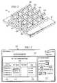
- FIG. 3is a block diagram depicting one embodiment of a BIOS interface screen display according to teachings of the present disclosure
- FIG. 4is a flow diagram depicting one embodiment of a method of operation of a BIOS according to teachings of the present disclosure.
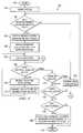
- FIG. 5is a flow diagram depicting one embodiment of a diagnostic routine for identifying one or more defective memory system devices according to teachings of the present disclosure.
- FIGS. 1 through 5Preferred embodiments and their advantages are best understood by reference to FIGS. 1 through 5 , wherein like numbers are used to indicate like and corresponding parts.
- an information handling systemmay include any instrumentality or aggregate of instrumentalities operable to compute, classify, process, transmit, receive, retrieve, originate, switch, store, display, manifest, detect, record, reproduce, handle, or utilize any form of information, intelligence, or data for business, scientific, control, or other purposes.
- an information handling systemmay be a personal computer, a network storage device, or any other suitable device and may vary in size, shape, performance, functionality, and price.
- the information handling systemmay include random access memory (RAM), one or more processing resources such as a central processing unit (CPU) or hardware or software control logic, ROM, and/or other types of nonvolatile memory.
- Additional components of the information handling systemmay include one or more disk drives, one or more network ports for communicating with external devices as well as various input and output (I/O) devices, such as a keyboard, a mouse, and a video display.
- the information handling systemmay also include one or more buses operable to transmit communications between the various hardware components.
- Information handling system or computer system 10preferably includes at least one microprocessor or central processing unit (CPU) 12 .
- CPU 12may include processor 14 for handling integer operations and coprocessor 16 for handling floating point operations.
- CPU 12is preferably coupled to cache 18 and memory controller 20 via CPU bus 22 .
- System controller I/O trap 24preferably couples CPU bus 22 to local bus 26 and may be generally characterized as part of a system controller.
- Main memory 28 of dynamic random access memory (DRAM) modulesis preferably coupled to CPU bus 22 by a memory controller 20 .
- main memory 28 and memory controller 20are two components or devices of a dual-channel memory system.
- memory controller 20may achieve dual-channel support through the employment of two independent memory controllers (not expressly shown).
- Memory controller 20is also preferably compatible with DDR (double data rate) main memory 28 , memory capable of transferring data on both the rising and falling edges of each clock cycle.
- Main memory 28may include a plurality of memory media, such as memory cards, memory sticks, etc.
- BIOS memory 30is also preferably coupled to local bus 26 .
- FLASH memory or other nonvolatile memorymay be used as BIOS memory 30 .
- a BIOS program(not expressly shown) is typically stored in BIOS memory 30 .
- the BIOS programpreferably includes software which facilitates interaction with and between the devices of information handling system 10 and such devices as a keyboard (not expressly shown), a mouse (not expressly shown), or one or more I/O devices.
- BIOS memory 30may also store system code (note expressly shown) operable to control a plurality of basic information handling system 10 operations. Additional detail of preferred BIOS capabilities will be discussed below with reference to FIGS. 3 through 5 .
- Graphics controller 32is preferably coupled to local bus 26 and to video memory 34 .
- Video memory 34is preferably operable to store information to be displayed on one or more display panels 36 .
- Display panel 36may be an active matrix or passive matrix liquid crystal display (LCD), a cathode ray tube (CRT) display or other display technology.
- LCDliquid crystal display
- CRTcathode ray tube
- graphics controller 32may also be coupled to an integrated display, such as in a portable information handling system implementation.
- Bus interface controller or expansion bus controller 38preferably couples local bus 26 to expansion bus 40 .
- expansion bus 40may be configured as an Industry Standard Architecture (“ISA”) bus.
- ISAIndustry Standard Architecture
- PCIPeripheral Component Interconnect
- One or more devicesmay be coupled to expansion bus 40 via one or more expansion card slots (not expressly shown).
- PCMCIA controller 42may also be included and is preferably coupled to expansion bus 40 as shown.
- PCMCIA controller 42is preferably coupled to a plurality of information handling system expansion slots 44 .
- Expansion slots 44may be configured to receive one or more PCMCIA expansion cards such as modems, fax cards, communications cards, and other input/output (I/O) devices.
- Interrupt request generator 46is also preferably coupled to expansion bus 40 .
- Interrupt request generator 46is preferably operable to issue an interrupt service request over a predetermined interrupt request line in response to receipt of a request to issue interrupt instruction from CPU 12 .
- I/O controller 48is also preferably coupled to expansion bus 40 .
- I/O controller 48preferably interfaces to an integrated drive electronics (IDE) hard drive device (HDD) 50 , CD-ROM (compact disk-read only memory) drive 52 and/or a floppy disk drive (FDD) 54 .
- IDEintegrated drive electronics
- HDDhard drive device
- CD-ROMcompact disk-read only memory
- FDDfloppy disk drive
- Other disk drive devices(not expressly shown) which may be interfaced to the I/O controller include a removable hard drive, a zip drive, a CD-RW (compact disk-read/write) drive, and a CD-DVD (compact disk—digital versatile disk) drive.
- Communication controller 56is preferably provided and enables information handling system 10 to communicate with communication network 58 , e.g., an Ethernet network.
- Communication network 58may include a local area network (LAN), wide area network (WAN), Internet, Intranet, wireless broadband or the like.
- Communication controller 56may be employed to form a network interface for communicating with other information handling systems (not expressly shown) coupled to communication network 58 .
- information handling system 10preferably includes power supply 60 , which provides power to the many components and/or devices that form information handling system 10 .
- Power supply 60may be a rechargeable battery, such as a nickel metal hydride (“NiMH”) or lithium ion battery, when information handling system 10 is embodied as a portable or notebook computer, an A/C (alternating current) power source, an uninterruptible power supply (UPS) or other power source.
- NiMHnickel metal hydride
- UPSuninterruptible power supply
- Power supply 60is preferably coupled to power management microcontroller 62 .
- Power management microcontroller 62preferably controls the distribution of power from power supply 60 . More specifically, power management microcontroller 62 preferably includes power output 64 coupled to main power plane 66 which may supply power to CPU 12 as well as other information handling system components. Power management microcontroller 62 may also be coupled to a power plane (not expressly shown) operable to supply power to an integrated panel display (not expressly shown), as well as to additional power delivery planes preferably included in information handling system 10 .
- Power management microcontroller 62preferably monitors a charge level of an attached battery or UPS to determine when and when not to charge the battery or UPS. Power management microcontroller 62 is preferably also coupled to main power switch 68 , which the user may actuate to turn information handling system 10 on and off. While power management microcontroller 62 powers down one or more portions or components of information handling system 10 , e.g., CPU 12 , display 36 , or HDD 50 , etc., when not in use to conserve power, power management microcontroller 62 itself is preferably substantially always coupled to a source of power, preferably power supply 60 .
- information handling system 10may also include screen lid switch or indicator 70 which provides an indication of when an integrated display is in an open position and an indication of when the integrated display is in a closed position.
- screen lid switch or indicator 70provides an indication of when an integrated display is in an open position and an indication of when the integrated display is in a closed position.
- an integrated panel displaymay be located in the same location in a lid (not expressly shown) of the computer as is typical for clamshell configurations of portable computers such as laptop or notebook computers. In this manner, the integrated display may form an integral part of the lid of the system, which swings from an open position to permit user interaction to a closed position.
- Computer system 10may also include power management chip set 72 .
- Power management chip set 72is preferably coupled to CPU 12 via local bus 26 so that power management chip set 72 may receive power management and control commands from CPU 12 .
- Power management chip set 72is preferably connected to a plurality of individual power planes operable to supply power to respective components of information handling system 10 , e.g., HDD 50 , FDD 54 , etc. In this manner, power management chip set 72 preferably acts under the direction of CPU 12 to control the power supplied to the various power planes and components of a system.
- Real-time clock (RTC) 74may also be coupled to I/O controller 48 and power management chip set 72 . Inclusion of RTC 74 permits timed events or alarms to be transmitted to power management chip set 72 . Real-time clock 74 may be programmed to generate an alarm signal at a predetermined time as well as to perform other operations.
- system or main memory 28is preferably implemented as dual-channel DDR memory.
- system or main memory 28is preferably implemented as dual-channel DDR memory.
- dual-channel DDR memory systemsnecessitates the use of a dual-channel memory controller with DDR capable memory devices.
- Memory controller 20the interface between the CPU and system memory, is typically included on the northbridge portion of the motherboard chip set. Besides handling data flow to and from the processor, memory controller 20 preferably also governs information handling system 10 memory system support for different types and speeds of memory, along with the maximum memory module size and installable memory ceiling.
- the standard configuration for most of today's information handling systemsis a single channel architecture.
- single channel architecturesIn addition to providing high availability, single channel architectures generally have the advantage of low cost and excellent memory compatibility and flexibility.
- a single channel memory controllertypically becomes a performance bottleneck when it cannot keep up with the CPU and CPU bus, leaving the processor to waste clock cycles with nothing to process.
- dual-channel memory architecturesTo cure the performance bottleneck typically experienced with single channel memory architectures, information handling system manufacturers have been quick to embrace the benefits of dual-channel memory architectures.
- the basic concept of dual-channel memory architecturesis adding a second memory channel to theoretically double the bandwidth of the memory system.
- the dual-channel memory architecture conceptturns older, slower, and cheaper memory into an up-to-date architecture by adding a second, parallel memory pathway.
- dual-channel controllerssimply take what is widely available and double it.
- dual-channel memory architecturesinclude two independent memory controllers. In operation, both memory controllers typically operate concurrently with one another and thereby hide latencies associated with conventional chip sets. For example, controller “A” may read or write to main memory while controller “B” prepares for the next access, and vice versa.
- DDR memoryreferring to that memory which transfers data on both the rising and falling edges of each clock cycle
- main memory 28 and memory controller 20 of information handling system 10typically increases performance significantly over single channel architectures and non DDR dual-channel memory architectures.
- main memory 28is preferably mounted to system board or motherboard 90 via slots 92 , 94 , 96 and 98 .
- DIMMs 100 , 102 , 104 and 106are preferably DDR enabled memory modules.
- memory slots 92 , 94 , 96 and 98are preferably operably coupled to dual-channel DDR memory controller 20 and processor 12 , dual-channel memory controller 20 being operably coupled to processor 12 via CPU bus 22 . While the present discussion refers to DIMMs, other memory device implementations are contemplated, e.g., single inline memory modules (SIMMs), memory sticks, etc.
- SIMMssingle inline memory modules
- a user or software applicationmay selectively enable and disable one or more devices of an information handling system memory system.
- such a systemmay convey many benefits on users of information handling systems employing dual-channel DDR memory systems.
- such capabilitiesmay enable a user or software application to more efficiently determine defective or faulty memory system devices or components in a dual-channel memory system implementation without requiring the typical iterative process of adding and removing DIMMs into memory slots of the system in an attempt to isolate either a defective DIMM or a defective memory slot.
- FIG. 3a block diagram depicting one embodiment of a BIOS interface incorporating teachings of the present disclosure is shown.
- FIG. 3generally illustrates an application interface through which a user or another application may selectively enable or disable one or more components of an information handling system memory system.
- Illustrated generally at 108 in FIG. 3is a screen shot or display of a portion of a BIOS utility whereby a user or diagnostic application may selectively control aspects of main memory 28 and/or memory controller 20 of information handing system 10 .
- the application responsible for generating display 108is preferably also capable of interacting with processor 12 , memory controller 20 and/or main memory 28 to enable one or more memory slots or DIMMs of main memory 28 to be selectively enabled, disabled or otherwise isolated.
- Such selective isolationpreferably enables the user or an additional software application to identify one or more devices of main memory 28 which may be causing one or more memory errors on information handling system 10 .
- Examples of memory errors which may prompt a user or additional software application to interrogate or otherwise query the memory system of information handling system 10 as to the operability of one or more memory devices included thereininclude, but are not limited to, failure of a memory diagnostic routine, the “blue screen” associated with Windows® based operating systems, as well as others.
- utility information section 110In the embodiment of display or screen shot 108 depicted in FIG. 3 , utility information section 110 , help or instruction section 112 and memory system device or component information and configuration section 114 are preferably included.
- memory system utility information section 110Preferably included in memory system utility information section 110 are such information as a memory system utility version number, directory information such as a page number, exit or escape information, as well as other information.
- help or instruction section 112are one or more instructions on the use of one or more components of the memory system configuration components in a BIOS utility incorporating teachings of the present disclosure.
- Memory system device or component information and configuration section 114 of display 108preferably communicates a number of items pertaining to one or more aspects of the memory system of information handling system 10 .
- memory system device or component information and configuration section 114preferably includes one or more memory system device or component representations 116 .
- memory system or device component representation section 116may include one or more representations for each DIMM or memory module of main memory 28 on information handling system 10 , one or more representations for each memory slot included in the memory system of information handling system 10 , a combination of the DIMMs and memory slots available on information handling system 10 , as well as other information.
- display 108preferably includes memory system device or component operating status section 118 in memory system device or component information and configuration section 114 .
- memory system device or component operating status section 118is an indication of the operating state of an associated memory system device or component. For example, in an embodiment of information handling system 10 including three DIMMs disposed in three respective memory slots, memory system device or component operating status section 118 will preferably reflect whether each of the DIMMs and/or memory slots containing a corresponding DIMM is currently disabled, enabled or in some alternative operating state.
- memory system device or component operating status section 118may serve as an interface enabling the user to selectively alter the operating status of a selected DIMM or memory slot.
- a usermay select memory slot two (2) or the DIMM disposed in memory slot two (2) to be disabled.
- one means for altering the operating state of a selected memory system device or componentmay be through the use of up or down cursor keys on a keyboard associated with information handling system 10 . Additional detail regarding selective enabling and disabling or otherwise altering a memory system DIMM or memory slot will be discussed in greater detail below with respect to FIGS. 4 and 5 .
- display 108may be adapted to convey additional information to a user or an additional software utility.
- memory system device or component information section 114may convey to a user whether each of the memory slots included on information handling system 10 is currently populated with a memory module such as a DIMM, SIMM, etc.
- memory system device or component information and configuration section 114may also convey one or more characteristics of a selected memory slot or a memory component disposed in a corresponding memory slot such as a memory device size or capacity, as indicated at 120 in FIG. 3 . Additional or alternative information may also be conveyed in display 108 without departing from the spirit and scope of teachings of the present disclosure.
- method 150 of FIG. 4preferably enables a user to view and alter the operating state of one or more devices of an information handling system memory system.
- method 150preferably proceeds to 154 where the BIOS, within which method 150 may be implemented, preferably queries information handling system 10 to identify one or more components thereof.
- information handling system 10is preferably queried at 154 to identify the one or more memory devices or components making up the memory system preferably included on information handling system 10 .
- the operating status of the one or more memory devices or components of the memory system of information handling system 10may be determined.
- additional aspects, characteristics or traits of the one or more devices or components included in the memory system of information handling system 10may be determined at 154 , e.g., memory card capacity, memory slot population, address ranges for the respective memory slots and memory cards.
- method 150preferably proceeds to 156 .
- user interaction with the BIOSis preferably monitored to identify user selection of the memory system device or component information and configuration page included therein. If at 156 it is determined that the user is not currently leveraging capabilities incorporated in the BIOS regarding enabling and disabling one or more memory system devices or components, method 150 preferably proceeds to 158 where other BIOS operations may be performed. Alternatively, if at 156 it is determined that the user has selected memory system device and component information and configuration capabilities included in the BIOS, method 150 preferably proceeds to 160 .
- method 150preferably enables display to the user, one or more memory system device or component representations. For example, display or screen shot 108 of FIG. 3 .
- method 150preferably also provides for the display of an operating status for each of the displayed memory system device or component representations at 162 , the operating status generally corresponding to a current operating state for a respective memory system device or component. For example, operating status region 118 of screen shot or display 108 generally illustrated in FIG. 3 .
- method 150preferably proceeds to 164 where a user entry may be awaited.
- the user entryUpon detection of a user entry, the user entry is preferably analyzed to determine whether the entry concerns alteration of one or more characteristics of a memory system device or component displayed or the user entry concerns other BIOS operations at 166 . If it is determined that the detected user entry concerns alteration of one or more characteristics of a memory system device or component, method 150 preferably proceeds to 168 . At 168 , a user desired operating state setting is preferably received by method 150 before proceeding to 170 . The displayed operating status for the selected memory system device or component is preferably changed at 170 , to reflect the user desired operating state for the selected memory system device or component. Upon effecting the change of display at 170 , method 150 preferably returns to 164 to await additional user entries.
- method 150preferably proceeds to 172 .
- the detected user entryis preferably evaluated to determine whether it is an escape or exit operation or whether it is an additional BIOS operation. If at 172 it is determined that the detected user entry is an additional BIOS operation, method 150 preferably proceeds to 158 where other BIOS operations may be performed before returning to 156 . Alternatively, if at 172 it is determined that the user entry is an escape or exit entry, method 150 preferably proceeds to 174 .
- the usermay be prompted to verify their desire to escape or exit the BIOS utility or, alternatively, to verify their desire to escape or exit the memory system component or device configuration and alteration capabilities of the BIOS. If at 174 the user indicates that they in fact do not desire to exit the BIOS utility or the memory system device or component alteration capabilities of the BIOS utility, method 150 preferably returns to 166 . Alternatively, if at 174 the user verifies their desire to exit or escape from the BIOS utility or the memory system device component configuration and alteration capabilities of the BIOS utility, method 150 preferably proceeds to 176 where the user may be prompted as to their desire to save any changes made during the current BIOS utility session.
- method 150preferably ends at 178 .
- method 150preferably proceeds to 180 where the selected changes are preferably effected by one or more BIOS operations, including effecting those changes to the operating state of the one or more selected memory devices or components. Method 150 then preferably ends at 178 .
- the information handling systemmay be operated in a variety of manners including, but not limited to, booting the system to an operating system or running one or more diagnostics routines.
- booting the systemto an operating system or running one or more diagnostics routines.
- diagnostics routinesmay be made with respect to method 150 without departing from the spirit and scope of teachings of the present disclosure.
- Method 200 of FIG. 5preferably includes the capability of selectively enabling and disabling memory system devices, in particular in dual-channel DDR memory system implementations, such that suspected faulty or defective memory system devices or components may be accurately diagnosed and subsequently repaired.
- method 200Upon initiation at 202 , for example, in response to user initiation of an information handling system memory system diagnostics routine, method 200 preferably proceeds to 204 where BIOS level memory system control teachings of the present disclosure may be accessed. Upon entering the memory system control BIOS utility at 204 , method 200 may utilize one or more methods to select one or more memory system devices or components for isolation and subsequent diagnostics testing. As discussed above, dual-channel DDR memory systems are generally difficult to diagnose. According to teachings of the present disclosure, temporarily reducing the complexity of such a memory system, such as by enabling only one device, the isolated device may be tested or diagnosed to determine its operational integrity.
- Isolating one or more memory system components or devices, DIMMs or memory slots for example,may be effected using a variety of methodologies.
- method 200may cooperate with a BIOS level memory system control to identify those memory system devices or components currently enabled and available for diagnostic testing.
- a log of previously tested memory system devices or componentsmay be accessed by method 200 and/or memory system information and configuration BIOS utility to identify those memory system devices or components still needing diagnostic testing.
- method 200may cooperate with a memory system control BIOS utility incorporating teachings of the present disclosure and perform diagnostic testing on each memory system device or component in sequential order, as presented by a BIOS included on information handling system 10 .
- method 200preferably proceeds to 208 where isolation of the selected memory system devices or components is preferably facilitated.
- facilitating isolation of one or more memory system devices or componentsmay involve disabling the memory slot associated with a particular memory module desired to be subjected to diagnostic testing.
- an address rangemay be associated with each memory slot such that facilitating isolation of one or more memory system devices or components may involve disabling or masking an address range associated with the memory devices or components selected to be isolated.
- one or more memory devices or componentsmay be effectively isolated by first permitting an application incorporating teachings of the present disclosure may facilitate switching of the memory system from dual-channel to single channel.
- additional hardwaremay be incorporated into information handling system 10 such that effective isolation of one or more memory system memory slots, memory cards or other memory system devices or components may be effected.
- diagnostic testingare preferably performed on the one or more isolated memory system devices or components.
- diagnostic testingmay assume many forms, e.g., a dedicated memory diagnostics application, booting to an operating system and observing any errors, etc.
- diagnosticsmay be run within the BIOS application, external to the BIOS, as well as using other implementations.
- method 200preferably logs the results from the diagnostic tests at 212 . For example, if DIMM A was tested and passed, a log entry indicating DIMM A successfully completed the diagnostic routine would preferably be made. Such a log may be maintained in a memory accessible by the BIOS, a diagnostic routine, an operating system, etc., and such that the log is not at risk for loss during an isolation routine.
- method 200preferably determined whether each memory system device or component to be subjected to diagnostic testing has been so subjected. For example, if a plurality of memory system devices or components were isolated at 206 and 208 , method 200 may first ensure each member of the plurality has been subjected to desired testing prior to looking to any remaining memory system device or components. In such a case, if the isolated plurality passes diagnostic testing, isolation of the individual components may be skipped and those memory systems devices or components excluded from the plurality may be tested in accordance with method 200 .
- method 200preferably returns to 206 where the next memory system component or device may be selected for isolation. Alternatively, if at 214 it has been determined that all memory system devices or components have been desirably tested, method 200 preferably proceeds to 216 .
- those devices whose diagnostic test results indicate faulty or defective hardwareare preferably disabled by the diagnostic routine incorporating teachings of the present disclosure.
- teachings of the present disclosuresuggest the software level capability of the present disclosure be incorporated in information handling system 10 which enables selective enabling and disabling of one or more memory system devices or components.
- method 200upon reviewing the log created at 212 , for example, may identify those devices whose diagnostic test results indicate faulty or failing devices or components and subsequently cooperate with a BIOS level memory system device or component control to disable such faulty or defective memory system devices or components at 216 .
- teachings of the present disclosureprovide for the maintaining of the disabled memory system devices or components throughout subsequent uses of information handling system 10 , such as until the faulty or defective memory system device or component is repaired, replaced or passes additional diagnostic testing.
- method 200preferably proceeds to 218 where the one or more memory system devices or components identified as defective or faulty and subsequently disabled may be reported to the user. Reporting such devices to the user may include display of one or more memory system device or component representations indicating the memory slot or DIMM modules disabled as a result of their failing diagnostic testing.
- method 200preferably proceeds to 220 where information handling system 10 may be returned to normal operations; e.g., rebooted to an operating system or a diagnostic routine, or other application without the services of the one or more disabled memory system devices or components. Method 200 then preferably ends at 222 .
Landscapes
- Engineering & Computer Science (AREA)
- General Engineering & Computer Science (AREA)
- Theoretical Computer Science (AREA)
- Computer Hardware Design (AREA)
- Quality & Reliability (AREA)
- Physics & Mathematics (AREA)
- General Physics & Mathematics (AREA)
- Techniques For Improving Reliability Of Storages (AREA)
Abstract
Description
Claims (23)
Priority Applications (1)
| Application Number | Priority Date | Filing Date | Title |
|---|---|---|---|
| US10/699,305US7370238B2 (en) | 2003-10-31 | 2003-10-31 | System, method and software for isolating dual-channel memory during diagnostics |
Applications Claiming Priority (1)
| Application Number | Priority Date | Filing Date | Title |
|---|---|---|---|
| US10/699,305US7370238B2 (en) | 2003-10-31 | 2003-10-31 | System, method and software for isolating dual-channel memory during diagnostics |
Publications (2)
| Publication Number | Publication Date |
|---|---|
| US20050102568A1 US20050102568A1 (en) | 2005-05-12 |
| US7370238B2true US7370238B2 (en) | 2008-05-06 |
Family
ID=34550921
Family Applications (1)
| Application Number | Title | Priority Date | Filing Date |
|---|---|---|---|
| US10/699,305Expired - LifetimeUS7370238B2 (en) | 2003-10-31 | 2003-10-31 | System, method and software for isolating dual-channel memory during diagnostics |
Country Status (1)
| Country | Link |
|---|---|
| US (1) | US7370238B2 (en) |
Cited By (18)
| Publication number | Priority date | Publication date | Assignee | Title |
|---|---|---|---|---|
| US20060117152A1 (en)* | 2004-01-05 | 2006-06-01 | Smart Modular Technologies Inc., A California Corporation | Transparent four rank memory module for standard two rank sub-systems |
| US20060277355A1 (en)* | 2005-06-01 | 2006-12-07 | Mark Ellsberry | Capacity-expanding memory device |
| US20090254732A1 (en)* | 2008-04-08 | 2009-10-08 | International Business Machines Corporation | Enabling Memory Module Slots In A Computing System After A Repair Action |
| US20090292910A1 (en)* | 2008-05-21 | 2009-11-26 | Dell Products, Lp | System and method of accessing bios change summary information within a bios operating environment |
| US20100082967A1 (en)* | 2008-09-26 | 2010-04-01 | Asustek Computer Inc. | Method for detecting memory training result and computer system using such method |
| US20100091540A1 (en)* | 2004-03-05 | 2010-04-15 | Netlist, Inc. | Memory module decoder |
| US20100128507A1 (en)* | 2004-03-05 | 2010-05-27 | Netlist, Inc. | Circuit providing load isolation and memory domain translation for memory module |
| US20100293410A1 (en)* | 2009-05-14 | 2010-11-18 | International Business Machines Corporation | Memory Downsizing In A Computer Memory Subsystem |
| US20110016269A1 (en)* | 2009-07-16 | 2011-01-20 | Hyun Lee | System and method of increasing addressable memory space on a memory board |
| US7916574B1 (en) | 2004-03-05 | 2011-03-29 | Netlist, Inc. | Circuit providing load isolation and memory domain translation for memory module |
| US8516185B2 (en) | 2009-07-16 | 2013-08-20 | Netlist, Inc. | System and method utilizing distributed byte-wise buffers on a memory module |
| US8843126B1 (en)* | 2012-08-03 | 2014-09-23 | The United States Of America As Represented By The Secretary Of The Navy | System for isolation testing of RF transmitters and receivers |
| US8848470B2 (en) | 2012-08-29 | 2014-09-30 | International Business Machines Corporation | Memory operation upon failure of one of two paired memory devices |
| US8996935B2 (en) | 2012-12-07 | 2015-03-31 | International Business Machines Corporation | Memory operation of paired memory devices |
| US9037809B1 (en) | 2008-04-14 | 2015-05-19 | Netlist, Inc. | Memory module with circuit providing load isolation and noise reduction |
| US9128632B2 (en) | 2009-07-16 | 2015-09-08 | Netlist, Inc. | Memory module with distributed data buffers and method of operation |
| US10324841B2 (en) | 2013-07-27 | 2019-06-18 | Netlist, Inc. | Memory module with local synchronization |
| US10657002B2 (en) | 2017-11-10 | 2020-05-19 | International Business Machines Corporation | Method and apparatus to rollback memory DIMM lane sparing |
Families Citing this family (9)
| Publication number | Priority date | Publication date | Assignee | Title |
|---|---|---|---|---|
| US8028207B1 (en)* | 2005-09-28 | 2011-09-27 | Google Inc. | Early memory test |
| JP4586750B2 (en)* | 2006-03-10 | 2010-11-24 | 日本電気株式会社 | Computer system and start monitoring method |
| US20090119422A1 (en)* | 2007-11-07 | 2009-05-07 | International Business Machines Corporation | Method and apparatus for performing maintenance operations on peripheral devices |
| TWI474260B (en)* | 2009-02-16 | 2015-02-21 | Asustek Comp Inc | Computer system, memory circuit and booting method thereof |
| US9262418B2 (en) | 2010-09-22 | 2016-02-16 | Hewlett-Packard Development Company, L.P. | Method and system for performing system maintenance in a computing device |
| US8788883B2 (en) | 2010-12-16 | 2014-07-22 | Dell Products L.P. | System and method for recovering from a configuration error |
| US10762006B2 (en)* | 2017-03-31 | 2020-09-01 | Intel Corporation | Techniques to dynamically enable memory channels on a compute platform |
| CN109254862B (en)* | 2018-08-21 | 2022-04-12 | 奇酷互联网络科技(深圳)有限公司 | Method for automatically repairing DDR (double data Rate) upset, mobile terminal and storage medium |
| US11948661B2 (en)* | 2020-06-05 | 2024-04-02 | Micron Technology, Inc. | Methods for tuning command/address bus timing and memory devices and memory systems using the same |
Citations (15)
| Publication number | Priority date | Publication date | Assignee | Title |
|---|---|---|---|---|
| US5119486A (en) | 1989-01-17 | 1992-06-02 | Prime Computer | Memory board selection method and apparatus |
| US5848018A (en)* | 1996-01-19 | 1998-12-08 | Stmicroelectronics, Inc. | Memory-row selector having a test function |
| US6055653A (en)* | 1998-04-27 | 2000-04-25 | Compaq Computer Corporation | Method and apparatus for testing gang memory modules |
| US20020010891A1 (en)* | 2000-05-12 | 2002-01-24 | International Business Machines Corporation | Redundant memory access system |
| US6408334B1 (en)* | 1999-01-13 | 2002-06-18 | Dell Usa, L.P. | Communications system for multiple computer system management circuits |
| US6421798B1 (en)* | 1999-07-14 | 2002-07-16 | Computer Service Technology, Inc. | Chipset-based memory testing for hot-pluggable memory |
| US6762615B2 (en)* | 2001-03-10 | 2004-07-13 | Samsung Electronics Co., Ltd. | Parallel test board used in testing semiconductor memory devices |
| US6766474B2 (en)* | 2000-12-21 | 2004-07-20 | Intel Corporation | Multi-staged bios-based memory testing |
| US20040158701A1 (en)* | 2003-02-12 | 2004-08-12 | Dell Products L.P. | Method of decreasing boot up time in a computer system |
| US6792561B1 (en)* | 1999-10-20 | 2004-09-14 | Kabushiki Kaisha Toshiba | Apparatus and method for controlling access to expansion memory for a computer system |
| US20040199830A1 (en)* | 2003-03-20 | 2004-10-07 | International Business Machines Corporation | Method and apparatus for isolating uncorrectable errors while system continues to run |
| US6862695B2 (en)* | 2001-03-30 | 2005-03-01 | Giga-Byte Technology Co., Ltd. | Method and device for identifying failed devices in computer |
| US20050257109A1 (en)* | 2003-03-20 | 2005-11-17 | Averbuj Roberto F | Built-in self-test (BIST) architecture having distributed interpretation and generalized command protocol |
| US6971049B2 (en)* | 2002-05-23 | 2005-11-29 | International Business Machines Corporation | Method and apparatus for detecting and isolating failures in equipment connected to a data bus |
| US7000159B2 (en)* | 2003-03-10 | 2006-02-14 | Dell Products L.P. | System and method for testing memory |
- 2003
- 2003-10-31USUS10/699,305patent/US7370238B2/ennot_activeExpired - Lifetime
Patent Citations (15)
| Publication number | Priority date | Publication date | Assignee | Title |
|---|---|---|---|---|
| US5119486A (en) | 1989-01-17 | 1992-06-02 | Prime Computer | Memory board selection method and apparatus |
| US5848018A (en)* | 1996-01-19 | 1998-12-08 | Stmicroelectronics, Inc. | Memory-row selector having a test function |
| US6055653A (en)* | 1998-04-27 | 2000-04-25 | Compaq Computer Corporation | Method and apparatus for testing gang memory modules |
| US6408334B1 (en)* | 1999-01-13 | 2002-06-18 | Dell Usa, L.P. | Communications system for multiple computer system management circuits |
| US6421798B1 (en)* | 1999-07-14 | 2002-07-16 | Computer Service Technology, Inc. | Chipset-based memory testing for hot-pluggable memory |
| US6792561B1 (en)* | 1999-10-20 | 2004-09-14 | Kabushiki Kaisha Toshiba | Apparatus and method for controlling access to expansion memory for a computer system |
| US20020010891A1 (en)* | 2000-05-12 | 2002-01-24 | International Business Machines Corporation | Redundant memory access system |
| US6766474B2 (en)* | 2000-12-21 | 2004-07-20 | Intel Corporation | Multi-staged bios-based memory testing |
| US6762615B2 (en)* | 2001-03-10 | 2004-07-13 | Samsung Electronics Co., Ltd. | Parallel test board used in testing semiconductor memory devices |
| US6862695B2 (en)* | 2001-03-30 | 2005-03-01 | Giga-Byte Technology Co., Ltd. | Method and device for identifying failed devices in computer |
| US6971049B2 (en)* | 2002-05-23 | 2005-11-29 | International Business Machines Corporation | Method and apparatus for detecting and isolating failures in equipment connected to a data bus |
| US20040158701A1 (en)* | 2003-02-12 | 2004-08-12 | Dell Products L.P. | Method of decreasing boot up time in a computer system |
| US7000159B2 (en)* | 2003-03-10 | 2006-02-14 | Dell Products L.P. | System and method for testing memory |
| US20040199830A1 (en)* | 2003-03-20 | 2004-10-07 | International Business Machines Corporation | Method and apparatus for isolating uncorrectable errors while system continues to run |
| US20050257109A1 (en)* | 2003-03-20 | 2005-11-17 | Averbuj Roberto F | Built-in self-test (BIST) architecture having distributed interpretation and generalized command protocol |
Non-Patent Citations (3)
| Title |
|---|
| ASUS TR-DLS Dual Socket 370 Motherboard User's Manual, Nov. 2001, ASUSTek Computer Inc., p. 67.* |
| AWARDBIOS 6.0 User Guide, Award Software International Inc., 1999, pp. 48-54.* |
| Rambus, Rambus RDRAM Overview, [retrieved on Jun. 2, 2006], Retrieved from the Internet: <URL: http//web.archive.org/web/20030201092035/http://www.rambus.com/products/rdram/>.* |
Cited By (48)
| Publication number | Priority date | Publication date | Assignee | Title |
|---|---|---|---|---|
| US20110125966A1 (en)* | 2004-01-05 | 2011-05-26 | Smart Modular Technologies, Inc. | Multi-rank memory module that emulates a memory module having a different number of ranks |
| US10755757B2 (en) | 2004-01-05 | 2020-08-25 | Smart Modular Technologies, Inc. | Multi-rank memory module that emulates a memory module having a different number of ranks |
| US20060117152A1 (en)* | 2004-01-05 | 2006-06-01 | Smart Modular Technologies Inc., A California Corporation | Transparent four rank memory module for standard two rank sub-systems |
| US8990489B2 (en) | 2004-01-05 | 2015-03-24 | Smart Modular Technologies, Inc. | Multi-rank memory module that emulates a memory module having a different number of ranks |
| US8626998B1 (en) | 2004-01-05 | 2014-01-07 | Smart Modular Technologies, Inc. | Multi-rank memory module that emulates a memory module having a different number of ranks |
| US8250295B2 (en) | 2004-01-05 | 2012-08-21 | Smart Modular Technologies, Inc. | Multi-rank memory module that emulates a memory module having a different number of ranks |
| US9858215B1 (en) | 2004-03-05 | 2018-01-02 | Netlist, Inc. | Memory module with data buffering |
| US8756364B1 (en) | 2004-03-05 | 2014-06-17 | Netlist, Inc. | Multirank DDR memory modual with load reduction |
| US7864627B2 (en) | 2004-03-05 | 2011-01-04 | Netlist, Inc. | Memory module decoder |
| US12222878B2 (en) | 2004-03-05 | 2025-02-11 | Netlist, Inc. | Memory module with data buffering |
| US7881150B2 (en) | 2004-03-05 | 2011-02-01 | Netlist, Inc. | Circuit providing load isolation and memory domain translation for memory module |
| US7916574B1 (en) | 2004-03-05 | 2011-03-29 | Netlist, Inc. | Circuit providing load isolation and memory domain translation for memory module |
| US20110085406A1 (en)* | 2004-03-05 | 2011-04-14 | Netlist, Inc. | Circuit providing load isolation and memory domain translation for memory module |
| US20110090749A1 (en)* | 2004-03-05 | 2011-04-21 | Netlist, Inc. | Circuit for providing chip-select signals to a plurality of ranks of a ddr memory module |
| US20100128507A1 (en)* | 2004-03-05 | 2010-05-27 | Netlist, Inc. | Circuit providing load isolation and memory domain translation for memory module |
| US11093417B2 (en) | 2004-03-05 | 2021-08-17 | Netlist, Inc. | Memory module with data buffering |
| US10489314B2 (en) | 2004-03-05 | 2019-11-26 | Netlist, Inc. | Memory module with data buffering |
| US8072837B1 (en) | 2004-03-05 | 2011-12-06 | Netlist, Inc. | Circuit providing load isolation and memory domain translation for memory module |
| US8081537B1 (en) | 2004-03-05 | 2011-12-20 | Netlist, Inc. | Circuit for providing chip-select signals to a plurality of ranks of a DDR memory module |
| US8081536B1 (en) | 2004-03-05 | 2011-12-20 | Netlist, Inc. | Circuit for memory module |
| US8081535B2 (en) | 2004-03-05 | 2011-12-20 | Netlist, Inc. | Circuit for providing chip-select signals to a plurality of ranks of a DDR memory module |
| US20100091540A1 (en)* | 2004-03-05 | 2010-04-15 | Netlist, Inc. | Memory module decoder |
| US8516188B1 (en) | 2004-03-05 | 2013-08-20 | Netlist, Inc. | Circuit for memory module |
| US20060277355A1 (en)* | 2005-06-01 | 2006-12-07 | Mark Ellsberry | Capacity-expanding memory device |
| US8006028B2 (en)* | 2008-04-08 | 2011-08-23 | International Business Machines Corporation | Enabling memory module slots in a computing system after a repair action |
| US20090254732A1 (en)* | 2008-04-08 | 2009-10-08 | International Business Machines Corporation | Enabling Memory Module Slots In A Computing System After A Repair Action |
| US9037809B1 (en) | 2008-04-14 | 2015-05-19 | Netlist, Inc. | Memory module with circuit providing load isolation and noise reduction |
| US20090292910A1 (en)* | 2008-05-21 | 2009-11-26 | Dell Products, Lp | System and method of accessing bios change summary information within a bios operating environment |
| US8504811B2 (en)* | 2008-05-21 | 2013-08-06 | Dell Products, Lp | System and method of accessing BIOS change summary information within a BIOS operating environment |
| US20100082967A1 (en)* | 2008-09-26 | 2010-04-01 | Asustek Computer Inc. | Method for detecting memory training result and computer system using such method |
| US20100293410A1 (en)* | 2009-05-14 | 2010-11-18 | International Business Machines Corporation | Memory Downsizing In A Computer Memory Subsystem |
| US7984326B2 (en)* | 2009-05-14 | 2011-07-19 | International Business Machines Corporation | Memory downsizing in a computer memory subsystem |
| US20110016269A1 (en)* | 2009-07-16 | 2011-01-20 | Hyun Lee | System and method of increasing addressable memory space on a memory board |
| US11994982B2 (en) | 2009-07-16 | 2024-05-28 | Netlist, Inc. | Memory module with distributed data buffers |
| US9128632B2 (en) | 2009-07-16 | 2015-09-08 | Netlist, Inc. | Memory module with distributed data buffers and method of operation |
| US8417870B2 (en) | 2009-07-16 | 2013-04-09 | Netlist, Inc. | System and method of increasing addressable memory space on a memory board |
| US8516185B2 (en) | 2009-07-16 | 2013-08-20 | Netlist, Inc. | System and method utilizing distributed byte-wise buffers on a memory module |
| US11762788B2 (en) | 2012-07-27 | 2023-09-19 | Netlist, Inc. | Memory module with timing-controlled data buffering |
| US10268608B2 (en) | 2012-07-27 | 2019-04-23 | Netlist, Inc. | Memory module with timing-controlled data paths in distributed data buffers |
| US10860506B2 (en) | 2012-07-27 | 2020-12-08 | Netlist, Inc. | Memory module with timing-controlled data buffering |
| US8843126B1 (en)* | 2012-08-03 | 2014-09-23 | The United States Of America As Represented By The Secretary Of The Navy | System for isolation testing of RF transmitters and receivers |
| US8848470B2 (en) | 2012-08-29 | 2014-09-30 | International Business Machines Corporation | Memory operation upon failure of one of two paired memory devices |
| US8964495B2 (en) | 2012-08-29 | 2015-02-24 | International Business Machines Corporation | Memory operation upon failure of one of two paired memory devices |
| US9147499B2 (en) | 2012-12-07 | 2015-09-29 | International Business Machines Corporation | Memory operation of paired memory devices |
| US8996935B2 (en) | 2012-12-07 | 2015-03-31 | International Business Machines Corporation | Memory operation of paired memory devices |
| US10884923B2 (en) | 2013-07-27 | 2021-01-05 | Netlist, Inc. | Memory module with local synchronization and method of operation |
| US10324841B2 (en) | 2013-07-27 | 2019-06-18 | Netlist, Inc. | Memory module with local synchronization |
| US10657002B2 (en) | 2017-11-10 | 2020-05-19 | International Business Machines Corporation | Method and apparatus to rollback memory DIMM lane sparing |
Also Published As
| Publication number | Publication date |
|---|---|
| US20050102568A1 (en) | 2005-05-12 |
Similar Documents
| Publication | Publication Date | Title |
|---|---|---|
| US7370238B2 (en) | System, method and software for isolating dual-channel memory during diagnostics | |
| US6216226B1 (en) | Method and system for dynamically selecting a boot process within a data processing system | |
| TWI317868B (en) | System and method to detect errors and predict potential failures | |
| US9218893B2 (en) | Memory testing in a data processing system | |
| US20030126498A1 (en) | Method and apparatus for functional redundancy check mode recovery | |
| US20030079007A1 (en) | Redundant source event log | |
| US9176837B2 (en) | In situ processor re-characterization | |
| US6550019B1 (en) | Method and apparatus for problem identification during initial program load in a multiprocessor system | |
| CN103430158B (en) | Use Execution Single Step to Diagnose Coding | |
| US6725396B2 (en) | Identifying field replaceable units responsible for faults detected with processor timeouts utilizing IPL boot progress indicator status | |
| US11360839B1 (en) | Systems and methods for storing error data from a crash dump in a computer system | |
| US8117430B2 (en) | Boot test system and method thereof | |
| US7228364B2 (en) | System and method of SCSI and SAS hardware validation | |
| US6625728B1 (en) | Method and apparatus for locating and displaying a defective component in a data processing system during a system startup using location and progress codes associated with the component | |
| US20140143601A1 (en) | Debug device and debug method | |
| US5894549A (en) | System and method for fault detection in microcontroller program memory | |
| US20050033952A1 (en) | Dynamic scheduling of diagnostic tests to be performed during a system boot process | |
| US8516311B2 (en) | System and method for testing peripheral component interconnect express switch | |
| US7529890B1 (en) | System, apparatus and method for facilitating on-chip testing | |
| US20090276615A1 (en) | Servo device auto-booted upon power supply recovery and method thereof | |
| US7984219B2 (en) | Enhanced CPU RASUM feature in ISS servers | |
| CN113407394B (en) | Method, device, equipment and medium for server RAS function test | |
| US7290128B2 (en) | Fault resilient boot method for multi-rail processors in a computer system by disabling processor with the failed voltage regulator to control rebooting of the processors | |
| EP4425338A1 (en) | Systems and methods for usage of spare cores in connection with in-field tests of operational cores | |
| US20080127229A1 (en) | Multiple interface standard support for redundant array of independent disks |
Legal Events
| Date | Code | Title | Description |
|---|---|---|---|
| AS | Assignment | Owner name:DELL PRODUCTS L.P., TEXAS Free format text:ASSIGNMENT OF ASSIGNORS INTEREST;ASSIGNORS:BILLICK, STEPHEN J.;KUMAR, SAURABH;REEL/FRAME:014673/0612 Effective date:20031030 | |
| STCF | Information on status: patent grant | Free format text:PATENTED CASE | |
| FEPP | Fee payment procedure | Free format text:PAYOR NUMBER ASSIGNED (ORIGINAL EVENT CODE: ASPN); ENTITY STATUS OF PATENT OWNER: LARGE ENTITY | |
| FPAY | Fee payment | Year of fee payment:4 | |
| AS | Assignment | Owner name:BANK OF AMERICA, N.A., AS ADMINISTRATIVE AGENT, TE Free format text:PATENT SECURITY AGREEMENT (ABL);ASSIGNORS:DELL INC.;APPASSURE SOFTWARE, INC.;ASAP SOFTWARE EXPRESS, INC.;AND OTHERS;REEL/FRAME:031898/0001 Effective date:20131029 Owner name:BANK OF AMERICA, N.A., AS COLLATERAL AGENT, NORTH CAROLINA Free format text:PATENT SECURITY AGREEMENT (TERM LOAN);ASSIGNORS:DELL INC.;APPASSURE SOFTWARE, INC.;ASAP SOFTWARE EXPRESS, INC.;AND OTHERS;REEL/FRAME:031899/0261 Effective date:20131029 Owner name:BANK OF AMERICA, N.A., AS ADMINISTRATIVE AGENT, TEXAS Free format text:PATENT SECURITY AGREEMENT (ABL);ASSIGNORS:DELL INC.;APPASSURE SOFTWARE, INC.;ASAP SOFTWARE EXPRESS, INC.;AND OTHERS;REEL/FRAME:031898/0001 Effective date:20131029 Owner name:BANK OF NEW YORK MELLON TRUST COMPANY, N.A., AS FIRST LIEN COLLATERAL AGENT, TEXAS Free format text:PATENT SECURITY AGREEMENT (NOTES);ASSIGNORS:APPASSURE SOFTWARE, INC.;ASAP SOFTWARE EXPRESS, INC.;BOOMI, INC.;AND OTHERS;REEL/FRAME:031897/0348 Effective date:20131029 Owner name:BANK OF AMERICA, N.A., AS COLLATERAL AGENT, NORTH Free format text:PATENT SECURITY AGREEMENT (TERM LOAN);ASSIGNORS:DELL INC.;APPASSURE SOFTWARE, INC.;ASAP SOFTWARE EXPRESS, INC.;AND OTHERS;REEL/FRAME:031899/0261 Effective date:20131029 Owner name:BANK OF NEW YORK MELLON TRUST COMPANY, N.A., AS FI Free format text:PATENT SECURITY AGREEMENT (NOTES);ASSIGNORS:APPASSURE SOFTWARE, INC.;ASAP SOFTWARE EXPRESS, INC.;BOOMI, INC.;AND OTHERS;REEL/FRAME:031897/0348 Effective date:20131029 | |
| FPAY | Fee payment | Year of fee payment:8 | |
| AS | Assignment | Owner name:DELL USA L.P., TEXAS Free format text:RELEASE BY SECURED PARTY;ASSIGNOR:BANK OF AMERICA, N.A., AS ADMINISTRATIVE AGENT;REEL/FRAME:040065/0216 Effective date:20160907 Owner name:FORCE10 NETWORKS, INC., CALIFORNIA Free format text:RELEASE BY SECURED PARTY;ASSIGNOR:BANK OF AMERICA, N.A., AS ADMINISTRATIVE AGENT;REEL/FRAME:040065/0216 Effective date:20160907 Owner name:COMPELLANT TECHNOLOGIES, INC., MINNESOTA Free format text:RELEASE BY SECURED PARTY;ASSIGNOR:BANK OF AMERICA, N.A., AS ADMINISTRATIVE AGENT;REEL/FRAME:040065/0216 Effective date:20160907 Owner name:PEROT SYSTEMS CORPORATION, TEXAS Free format text:RELEASE BY SECURED PARTY;ASSIGNOR:BANK OF AMERICA, N.A., AS ADMINISTRATIVE AGENT;REEL/FRAME:040065/0216 Effective date:20160907 Owner name:DELL SOFTWARE INC., CALIFORNIA Free format text:RELEASE BY SECURED PARTY;ASSIGNOR:BANK OF AMERICA, N.A., AS ADMINISTRATIVE AGENT;REEL/FRAME:040065/0216 Effective date:20160907 Owner name:DELL MARKETING L.P., TEXAS Free format text:RELEASE BY SECURED PARTY;ASSIGNOR:BANK OF AMERICA, N.A., AS ADMINISTRATIVE AGENT;REEL/FRAME:040065/0216 Effective date:20160907 Owner name:WYSE TECHNOLOGY L.L.C., CALIFORNIA Free format text:RELEASE BY SECURED PARTY;ASSIGNOR:BANK OF AMERICA, N.A., AS ADMINISTRATIVE AGENT;REEL/FRAME:040065/0216 Effective date:20160907 Owner name:CREDANT TECHNOLOGIES, INC., TEXAS Free format text:RELEASE BY SECURED PARTY;ASSIGNOR:BANK OF AMERICA, N.A., AS ADMINISTRATIVE AGENT;REEL/FRAME:040065/0216 Effective date:20160907 Owner name:DELL INC., TEXAS Free format text:RELEASE BY SECURED PARTY;ASSIGNOR:BANK OF AMERICA, N.A., AS ADMINISTRATIVE AGENT;REEL/FRAME:040065/0216 Effective date:20160907 Owner name:ASAP SOFTWARE EXPRESS, INC., ILLINOIS Free format text:RELEASE BY SECURED PARTY;ASSIGNOR:BANK OF AMERICA, N.A., AS ADMINISTRATIVE AGENT;REEL/FRAME:040065/0216 Effective date:20160907 Owner name:APPASSURE SOFTWARE, INC., VIRGINIA Free format text:RELEASE BY SECURED PARTY;ASSIGNOR:BANK OF AMERICA, N.A., AS ADMINISTRATIVE AGENT;REEL/FRAME:040065/0216 Effective date:20160907 Owner name:DELL PRODUCTS L.P., TEXAS Free format text:RELEASE BY SECURED PARTY;ASSIGNOR:BANK OF AMERICA, N.A., AS ADMINISTRATIVE AGENT;REEL/FRAME:040065/0216 Effective date:20160907 Owner name:SECUREWORKS, INC., GEORGIA Free format text:RELEASE BY SECURED PARTY;ASSIGNOR:BANK OF AMERICA, N.A., AS ADMINISTRATIVE AGENT;REEL/FRAME:040065/0216 Effective date:20160907 | |
| AS | Assignment | Owner name:DELL PRODUCTS L.P., TEXAS Free format text:RELEASE BY SECURED PARTY;ASSIGNOR:BANK OF AMERICA, N.A., AS COLLATERAL AGENT;REEL/FRAME:040040/0001 Effective date:20160907 Owner name:DELL MARKETING L.P., TEXAS Free format text:RELEASE BY SECURED PARTY;ASSIGNOR:BANK OF AMERICA, N.A., AS COLLATERAL AGENT;REEL/FRAME:040040/0001 Effective date:20160907 Owner name:SECUREWORKS, INC., GEORGIA Free format text:RELEASE BY SECURED PARTY;ASSIGNOR:BANK OF AMERICA, N.A., AS COLLATERAL AGENT;REEL/FRAME:040040/0001 Effective date:20160907 Owner name:COMPELLENT TECHNOLOGIES, INC., MINNESOTA Free format text:RELEASE BY SECURED PARTY;ASSIGNOR:BANK OF AMERICA, N.A., AS COLLATERAL AGENT;REEL/FRAME:040040/0001 Effective date:20160907 Owner name:PEROT SYSTEMS CORPORATION, TEXAS Free format text:RELEASE BY SECURED PARTY;ASSIGNOR:BANK OF AMERICA, N.A., AS COLLATERAL AGENT;REEL/FRAME:040040/0001 Effective date:20160907 Owner name:WYSE TECHNOLOGY L.L.C., CALIFORNIA Free format text:RELEASE BY SECURED PARTY;ASSIGNOR:BANK OF AMERICA, N.A., AS COLLATERAL AGENT;REEL/FRAME:040040/0001 Effective date:20160907 Owner name:APPASSURE SOFTWARE, INC., VIRGINIA Free format text:RELEASE BY SECURED PARTY;ASSIGNOR:BANK OF AMERICA, N.A., AS COLLATERAL AGENT;REEL/FRAME:040040/0001 Effective date:20160907 Owner name:ASAP SOFTWARE EXPRESS, INC., ILLINOIS Free format text:RELEASE BY SECURED PARTY;ASSIGNOR:BANK OF AMERICA, N.A., AS COLLATERAL AGENT;REEL/FRAME:040040/0001 Effective date:20160907 Owner name:DELL INC., TEXAS Free format text:RELEASE BY SECURED PARTY;ASSIGNOR:BANK OF AMERICA, N.A., AS COLLATERAL AGENT;REEL/FRAME:040040/0001 Effective date:20160907 Owner name:CREDANT TECHNOLOGIES, INC., TEXAS Free format text:RELEASE BY SECURED PARTY;ASSIGNOR:BANK OF AMERICA, N.A., AS COLLATERAL AGENT;REEL/FRAME:040040/0001 Effective date:20160907 Owner name:DELL USA L.P., TEXAS Free format text:RELEASE BY SECURED PARTY;ASSIGNOR:BANK OF AMERICA, N.A., AS COLLATERAL AGENT;REEL/FRAME:040040/0001 Effective date:20160907 Owner name:FORCE10 NETWORKS, INC., CALIFORNIA Free format text:RELEASE BY SECURED PARTY;ASSIGNOR:BANK OF AMERICA, N.A., AS COLLATERAL AGENT;REEL/FRAME:040040/0001 Effective date:20160907 Owner name:DELL SOFTWARE INC., CALIFORNIA Free format text:RELEASE BY SECURED PARTY;ASSIGNOR:BANK OF AMERICA, N.A., AS COLLATERAL AGENT;REEL/FRAME:040040/0001 Effective date:20160907 Owner name:DELL USA L.P., TEXAS Free format text:RELEASE BY SECURED PARTY;ASSIGNOR:BANK OF NEW YORK MELLON TRUST COMPANY, N.A., AS COLLATERAL AGENT;REEL/FRAME:040065/0618 Effective date:20160907 Owner name:ASAP SOFTWARE EXPRESS, INC., ILLINOIS Free format text:RELEASE BY SECURED PARTY;ASSIGNOR:BANK OF NEW YORK MELLON TRUST COMPANY, N.A., AS COLLATERAL AGENT;REEL/FRAME:040065/0618 Effective date:20160907 Owner name:WYSE TECHNOLOGY L.L.C., CALIFORNIA Free format text:RELEASE BY SECURED PARTY;ASSIGNOR:BANK OF NEW YORK MELLON TRUST COMPANY, N.A., AS COLLATERAL AGENT;REEL/FRAME:040065/0618 Effective date:20160907 Owner name:CREDANT TECHNOLOGIES, INC., TEXAS Free format text:RELEASE BY SECURED PARTY;ASSIGNOR:BANK OF NEW YORK MELLON TRUST COMPANY, N.A., AS COLLATERAL AGENT;REEL/FRAME:040065/0618 Effective date:20160907 Owner name:COMPELLENT TECHNOLOGIES, INC., MINNESOTA Free format text:RELEASE BY SECURED PARTY;ASSIGNOR:BANK OF NEW YORK MELLON TRUST COMPANY, N.A., AS COLLATERAL AGENT;REEL/FRAME:040065/0618 Effective date:20160907 Owner name:PEROT SYSTEMS CORPORATION, TEXAS Free format text:RELEASE BY SECURED PARTY;ASSIGNOR:BANK OF NEW YORK MELLON TRUST COMPANY, N.A., AS COLLATERAL AGENT;REEL/FRAME:040065/0618 Effective date:20160907 Owner name:DELL MARKETING L.P., TEXAS Free format text:RELEASE BY SECURED PARTY;ASSIGNOR:BANK OF NEW YORK MELLON TRUST COMPANY, N.A., AS COLLATERAL AGENT;REEL/FRAME:040065/0618 Effective date:20160907 Owner name:DELL PRODUCTS L.P., TEXAS Free format text:RELEASE BY SECURED PARTY;ASSIGNOR:BANK OF NEW YORK MELLON TRUST COMPANY, N.A., AS COLLATERAL AGENT;REEL/FRAME:040065/0618 Effective date:20160907 Owner name:APPASSURE SOFTWARE, INC., VIRGINIA Free format text:RELEASE BY SECURED PARTY;ASSIGNOR:BANK OF NEW YORK MELLON TRUST COMPANY, N.A., AS COLLATERAL AGENT;REEL/FRAME:040065/0618 Effective date:20160907 Owner name:DELL SOFTWARE INC., CALIFORNIA Free format text:RELEASE BY SECURED PARTY;ASSIGNOR:BANK OF NEW YORK MELLON TRUST COMPANY, N.A., AS COLLATERAL AGENT;REEL/FRAME:040065/0618 Effective date:20160907 Owner name:FORCE10 NETWORKS, INC., CALIFORNIA Free format text:RELEASE BY SECURED PARTY;ASSIGNOR:BANK OF NEW YORK MELLON TRUST COMPANY, N.A., AS COLLATERAL AGENT;REEL/FRAME:040065/0618 Effective date:20160907 Owner name:DELL INC., TEXAS Free format text:RELEASE BY SECURED PARTY;ASSIGNOR:BANK OF NEW YORK MELLON TRUST COMPANY, N.A., AS COLLATERAL AGENT;REEL/FRAME:040065/0618 Effective date:20160907 Owner name:SECUREWORKS, INC., GEORGIA Free format text:RELEASE BY SECURED PARTY;ASSIGNOR:BANK OF NEW YORK MELLON TRUST COMPANY, N.A., AS COLLATERAL AGENT;REEL/FRAME:040065/0618 Effective date:20160907 | |
| AS | Assignment | Owner name:CREDIT SUISSE AG, CAYMAN ISLANDS BRANCH, AS COLLATERAL AGENT, NORTH CAROLINA Free format text:SECURITY AGREEMENT;ASSIGNORS:ASAP SOFTWARE EXPRESS, INC.;AVENTAIL LLC;CREDANT TECHNOLOGIES, INC.;AND OTHERS;REEL/FRAME:040134/0001 Effective date:20160907 Owner name:THE BANK OF NEW YORK MELLON TRUST COMPANY, N.A., AS NOTES COLLATERAL AGENT, TEXAS Free format text:SECURITY AGREEMENT;ASSIGNORS:ASAP SOFTWARE EXPRESS, INC.;AVENTAIL LLC;CREDANT TECHNOLOGIES, INC.;AND OTHERS;REEL/FRAME:040136/0001 Effective date:20160907 Owner name:CREDIT SUISSE AG, CAYMAN ISLANDS BRANCH, AS COLLAT Free format text:SECURITY AGREEMENT;ASSIGNORS:ASAP SOFTWARE EXPRESS, INC.;AVENTAIL LLC;CREDANT TECHNOLOGIES, INC.;AND OTHERS;REEL/FRAME:040134/0001 Effective date:20160907 Owner name:THE BANK OF NEW YORK MELLON TRUST COMPANY, N.A., A Free format text:SECURITY AGREEMENT;ASSIGNORS:ASAP SOFTWARE EXPRESS, INC.;AVENTAIL LLC;CREDANT TECHNOLOGIES, INC.;AND OTHERS;REEL/FRAME:040136/0001 Effective date:20160907 | |
| AS | Assignment | Owner name:THE BANK OF NEW YORK MELLON TRUST COMPANY, N.A., T Free format text:SECURITY AGREEMENT;ASSIGNORS:CREDANT TECHNOLOGIES, INC.;DELL INTERNATIONAL L.L.C.;DELL MARKETING L.P.;AND OTHERS;REEL/FRAME:049452/0223 Effective date:20190320 Owner name:THE BANK OF NEW YORK MELLON TRUST COMPANY, N.A., TEXAS Free format text:SECURITY AGREEMENT;ASSIGNORS:CREDANT TECHNOLOGIES, INC.;DELL INTERNATIONAL L.L.C.;DELL MARKETING L.P.;AND OTHERS;REEL/FRAME:049452/0223 Effective date:20190320 | |
| MAFP | Maintenance fee payment | Free format text:PAYMENT OF MAINTENANCE FEE, 12TH YEAR, LARGE ENTITY (ORIGINAL EVENT CODE: M1553); ENTITY STATUS OF PATENT OWNER: LARGE ENTITY Year of fee payment:12 | |
| AS | Assignment | Owner name:THE BANK OF NEW YORK MELLON TRUST COMPANY, N.A., TEXAS Free format text:SECURITY AGREEMENT;ASSIGNORS:CREDANT TECHNOLOGIES INC.;DELL INTERNATIONAL L.L.C.;DELL MARKETING L.P.;AND OTHERS;REEL/FRAME:053546/0001 Effective date:20200409 | |
| AS | Assignment | Owner name:WYSE TECHNOLOGY L.L.C., CALIFORNIA Free format text:RELEASE BY SECURED PARTY;ASSIGNOR:CREDIT SUISSE AG, CAYMAN ISLANDS BRANCH;REEL/FRAME:058216/0001 Effective date:20211101 Owner name:SCALEIO LLC, MASSACHUSETTS Free format text:RELEASE BY SECURED PARTY;ASSIGNOR:CREDIT SUISSE AG, CAYMAN ISLANDS BRANCH;REEL/FRAME:058216/0001 Effective date:20211101 Owner name:MOZY, INC., WASHINGTON Free format text:RELEASE BY SECURED PARTY;ASSIGNOR:CREDIT SUISSE AG, CAYMAN ISLANDS BRANCH;REEL/FRAME:058216/0001 Effective date:20211101 Owner name:MAGINATICS LLC, CALIFORNIA Free format text:RELEASE BY SECURED PARTY;ASSIGNOR:CREDIT SUISSE AG, CAYMAN ISLANDS BRANCH;REEL/FRAME:058216/0001 Effective date:20211101 Owner name:FORCE10 NETWORKS, INC., CALIFORNIA Free format text:RELEASE BY SECURED PARTY;ASSIGNOR:CREDIT SUISSE AG, CAYMAN ISLANDS BRANCH;REEL/FRAME:058216/0001 Effective date:20211101 Owner name:EMC IP HOLDING COMPANY LLC, TEXAS Free format text:RELEASE BY SECURED PARTY;ASSIGNOR:CREDIT SUISSE AG, CAYMAN ISLANDS BRANCH;REEL/FRAME:058216/0001 Effective date:20211101 Owner name:EMC CORPORATION, MASSACHUSETTS Free format text:RELEASE BY SECURED PARTY;ASSIGNOR:CREDIT SUISSE AG, CAYMAN ISLANDS BRANCH;REEL/FRAME:058216/0001 Effective date:20211101 Owner name:DELL SYSTEMS CORPORATION, TEXAS Free format text:RELEASE BY SECURED PARTY;ASSIGNOR:CREDIT SUISSE AG, CAYMAN ISLANDS BRANCH;REEL/FRAME:058216/0001 Effective date:20211101 Owner name:DELL SOFTWARE INC., CALIFORNIA Free format text:RELEASE BY SECURED PARTY;ASSIGNOR:CREDIT SUISSE AG, CAYMAN ISLANDS BRANCH;REEL/FRAME:058216/0001 Effective date:20211101 Owner name:DELL PRODUCTS L.P., TEXAS Free format text:RELEASE BY SECURED PARTY;ASSIGNOR:CREDIT SUISSE AG, CAYMAN ISLANDS BRANCH;REEL/FRAME:058216/0001 Effective date:20211101 Owner name:DELL MARKETING L.P., TEXAS Free format text:RELEASE BY SECURED PARTY;ASSIGNOR:CREDIT SUISSE AG, CAYMAN ISLANDS BRANCH;REEL/FRAME:058216/0001 Effective date:20211101 Owner name:DELL INTERNATIONAL, L.L.C., TEXAS Free format text:RELEASE BY SECURED PARTY;ASSIGNOR:CREDIT SUISSE AG, CAYMAN ISLANDS BRANCH;REEL/FRAME:058216/0001 Effective date:20211101 Owner name:DELL USA L.P., TEXAS Free format text:RELEASE BY SECURED PARTY;ASSIGNOR:CREDIT SUISSE AG, CAYMAN ISLANDS BRANCH;REEL/FRAME:058216/0001 Effective date:20211101 Owner name:CREDANT TECHNOLOGIES, INC., TEXAS Free format text:RELEASE BY SECURED PARTY;ASSIGNOR:CREDIT SUISSE AG, CAYMAN ISLANDS BRANCH;REEL/FRAME:058216/0001 Effective date:20211101 Owner name:AVENTAIL LLC, CALIFORNIA Free format text:RELEASE BY SECURED PARTY;ASSIGNOR:CREDIT SUISSE AG, CAYMAN ISLANDS BRANCH;REEL/FRAME:058216/0001 Effective date:20211101 Owner name:ASAP SOFTWARE EXPRESS, INC., ILLINOIS Free format text:RELEASE BY SECURED PARTY;ASSIGNOR:CREDIT SUISSE AG, CAYMAN ISLANDS BRANCH;REEL/FRAME:058216/0001 Effective date:20211101 | |
| AS | Assignment | Owner name:SCALEIO LLC, MASSACHUSETTS Free format text:RELEASE OF SECURITY INTEREST IN PATENTS PREVIOUSLY RECORDED AT REEL/FRAME (040136/0001);ASSIGNOR:THE BANK OF NEW YORK MELLON TRUST COMPANY, N.A., AS NOTES COLLATERAL AGENT;REEL/FRAME:061324/0001 Effective date:20220329 Owner name:EMC IP HOLDING COMPANY LLC (ON BEHALF OF ITSELF AND AS SUCCESSOR-IN-INTEREST TO MOZY, INC.), TEXAS Free format text:RELEASE OF SECURITY INTEREST IN PATENTS PREVIOUSLY RECORDED AT REEL/FRAME (040136/0001);ASSIGNOR:THE BANK OF NEW YORK MELLON TRUST COMPANY, N.A., AS NOTES COLLATERAL AGENT;REEL/FRAME:061324/0001 Effective date:20220329 Owner name:EMC CORPORATION (ON BEHALF OF ITSELF AND AS SUCCESSOR-IN-INTEREST TO MAGINATICS LLC), MASSACHUSETTS Free format text:RELEASE OF SECURITY INTEREST IN PATENTS PREVIOUSLY RECORDED AT REEL/FRAME (040136/0001);ASSIGNOR:THE BANK OF NEW YORK MELLON TRUST COMPANY, N.A., AS NOTES COLLATERAL AGENT;REEL/FRAME:061324/0001 Effective date:20220329 Owner name:DELL MARKETING CORPORATION (SUCCESSOR-IN-INTEREST TO FORCE10 NETWORKS, INC. AND WYSE TECHNOLOGY L.L.C.), TEXAS Free format text:RELEASE OF SECURITY INTEREST IN PATENTS PREVIOUSLY RECORDED AT REEL/FRAME (040136/0001);ASSIGNOR:THE BANK OF NEW YORK MELLON TRUST COMPANY, N.A., AS NOTES COLLATERAL AGENT;REEL/FRAME:061324/0001 Effective date:20220329 Owner name:DELL PRODUCTS L.P., TEXAS Free format text:RELEASE OF SECURITY INTEREST IN PATENTS PREVIOUSLY RECORDED AT REEL/FRAME (040136/0001);ASSIGNOR:THE BANK OF NEW YORK MELLON TRUST COMPANY, N.A., AS NOTES COLLATERAL AGENT;REEL/FRAME:061324/0001 Effective date:20220329 Owner name:DELL INTERNATIONAL L.L.C., TEXAS Free format text:RELEASE OF SECURITY INTEREST IN PATENTS PREVIOUSLY RECORDED AT REEL/FRAME (040136/0001);ASSIGNOR:THE BANK OF NEW YORK MELLON TRUST COMPANY, N.A., AS NOTES COLLATERAL AGENT;REEL/FRAME:061324/0001 Effective date:20220329 Owner name:DELL USA L.P., TEXAS Free format text:RELEASE OF SECURITY INTEREST IN PATENTS PREVIOUSLY RECORDED AT REEL/FRAME (040136/0001);ASSIGNOR:THE BANK OF NEW YORK MELLON TRUST COMPANY, N.A., AS NOTES COLLATERAL AGENT;REEL/FRAME:061324/0001 Effective date:20220329 Owner name:DELL MARKETING L.P. (ON BEHALF OF ITSELF AND AS SUCCESSOR-IN-INTEREST TO CREDANT TECHNOLOGIES, INC.), TEXAS Free format text:RELEASE OF SECURITY INTEREST IN PATENTS PREVIOUSLY RECORDED AT REEL/FRAME (040136/0001);ASSIGNOR:THE BANK OF NEW YORK MELLON TRUST COMPANY, N.A., AS NOTES COLLATERAL AGENT;REEL/FRAME:061324/0001 Effective date:20220329 Owner name:DELL MARKETING CORPORATION (SUCCESSOR-IN-INTEREST TO ASAP SOFTWARE EXPRESS, INC.), TEXAS Free format text:RELEASE OF SECURITY INTEREST IN PATENTS PREVIOUSLY RECORDED AT REEL/FRAME (040136/0001);ASSIGNOR:THE BANK OF NEW YORK MELLON TRUST COMPANY, N.A., AS NOTES COLLATERAL AGENT;REEL/FRAME:061324/0001 Effective date:20220329 | |
| AS | Assignment | Owner name:SCALEIO LLC, MASSACHUSETTS Free format text:RELEASE OF SECURITY INTEREST IN PATENTS PREVIOUSLY RECORDED AT REEL/FRAME (045455/0001);ASSIGNOR:THE BANK OF NEW YORK MELLON TRUST COMPANY, N.A., AS NOTES COLLATERAL AGENT;REEL/FRAME:061753/0001 Effective date:20220329 Owner name:EMC IP HOLDING COMPANY LLC (ON BEHALF OF ITSELF AND AS SUCCESSOR-IN-INTEREST TO MOZY, INC.), TEXAS Free format text:RELEASE OF SECURITY INTEREST IN PATENTS PREVIOUSLY RECORDED AT REEL/FRAME (045455/0001);ASSIGNOR:THE BANK OF NEW YORK MELLON TRUST COMPANY, N.A., AS NOTES COLLATERAL AGENT;REEL/FRAME:061753/0001 Effective date:20220329 Owner name:EMC CORPORATION (ON BEHALF OF ITSELF AND AS SUCCESSOR-IN-INTEREST TO MAGINATICS LLC), MASSACHUSETTS Free format text:RELEASE OF SECURITY INTEREST IN PATENTS PREVIOUSLY RECORDED AT REEL/FRAME (045455/0001);ASSIGNOR:THE BANK OF NEW YORK MELLON TRUST COMPANY, N.A., AS NOTES COLLATERAL AGENT;REEL/FRAME:061753/0001 Effective date:20220329 Owner name:DELL MARKETING CORPORATION (SUCCESSOR-IN-INTEREST TO FORCE10 NETWORKS, INC. AND WYSE TECHNOLOGY L.L.C.), TEXAS Free format text:RELEASE OF SECURITY INTEREST IN PATENTS PREVIOUSLY RECORDED AT REEL/FRAME (045455/0001);ASSIGNOR:THE BANK OF NEW YORK MELLON TRUST COMPANY, N.A., AS NOTES COLLATERAL AGENT;REEL/FRAME:061753/0001 Effective date:20220329 Owner name:DELL PRODUCTS L.P., TEXAS Free format text:RELEASE OF SECURITY INTEREST IN PATENTS PREVIOUSLY RECORDED AT REEL/FRAME (045455/0001);ASSIGNOR:THE BANK OF NEW YORK MELLON TRUST COMPANY, N.A., AS NOTES COLLATERAL AGENT;REEL/FRAME:061753/0001 Effective date:20220329 Owner name:DELL INTERNATIONAL L.L.C., TEXAS Free format text:RELEASE OF SECURITY INTEREST IN PATENTS PREVIOUSLY RECORDED AT REEL/FRAME (045455/0001);ASSIGNOR:THE BANK OF NEW YORK MELLON TRUST COMPANY, N.A., AS NOTES COLLATERAL AGENT;REEL/FRAME:061753/0001 Effective date:20220329 Owner name:DELL USA L.P., TEXAS Free format text:RELEASE OF SECURITY INTEREST IN PATENTS PREVIOUSLY RECORDED AT REEL/FRAME (045455/0001);ASSIGNOR:THE BANK OF NEW YORK MELLON TRUST COMPANY, N.A., AS NOTES COLLATERAL AGENT;REEL/FRAME:061753/0001 Effective date:20220329 Owner name:DELL MARKETING L.P. (ON BEHALF OF ITSELF AND AS SUCCESSOR-IN-INTEREST TO CREDANT TECHNOLOGIES, INC.), TEXAS Free format text:RELEASE OF SECURITY INTEREST IN PATENTS PREVIOUSLY RECORDED AT REEL/FRAME (045455/0001);ASSIGNOR:THE BANK OF NEW YORK MELLON TRUST COMPANY, N.A., AS NOTES COLLATERAL AGENT;REEL/FRAME:061753/0001 Effective date:20220329 Owner name:DELL MARKETING CORPORATION (SUCCESSOR-IN-INTEREST TO ASAP SOFTWARE EXPRESS, INC.), TEXAS Free format text:RELEASE OF SECURITY INTEREST IN PATENTS PREVIOUSLY RECORDED AT REEL/FRAME (045455/0001);ASSIGNOR:THE BANK OF NEW YORK MELLON TRUST COMPANY, N.A., AS NOTES COLLATERAL AGENT;REEL/FRAME:061753/0001 Effective date:20220329 | |
| AS | Assignment | Owner name:DELL MARKETING L.P. (ON BEHALF OF ITSELF AND AS SUCCESSOR-IN-INTEREST TO CREDANT TECHNOLOGIES, INC.), TEXAS Free format text:RELEASE OF SECURITY INTEREST IN PATENTS PREVIOUSLY RECORDED AT REEL/FRAME (053546/0001);ASSIGNOR:THE BANK OF NEW YORK MELLON TRUST COMPANY, N.A., AS NOTES COLLATERAL AGENT;REEL/FRAME:071642/0001 Effective date:20220329 Owner name:DELL INTERNATIONAL L.L.C., TEXAS Free format text:RELEASE OF SECURITY INTEREST IN PATENTS PREVIOUSLY RECORDED AT REEL/FRAME (053546/0001);ASSIGNOR:THE BANK OF NEW YORK MELLON TRUST COMPANY, N.A., AS NOTES COLLATERAL AGENT;REEL/FRAME:071642/0001 Effective date:20220329 Owner name:DELL PRODUCTS L.P., TEXAS Free format text:RELEASE OF SECURITY INTEREST IN PATENTS PREVIOUSLY RECORDED AT REEL/FRAME (053546/0001);ASSIGNOR:THE BANK OF NEW YORK MELLON TRUST COMPANY, N.A., AS NOTES COLLATERAL AGENT;REEL/FRAME:071642/0001 Effective date:20220329 Owner name:DELL USA L.P., TEXAS Free format text:RELEASE OF SECURITY INTEREST IN PATENTS PREVIOUSLY RECORDED AT REEL/FRAME (053546/0001);ASSIGNOR:THE BANK OF NEW YORK MELLON TRUST COMPANY, N.A., AS NOTES COLLATERAL AGENT;REEL/FRAME:071642/0001 Effective date:20220329 Owner name:EMC CORPORATION, MASSACHUSETTS Free format text:RELEASE OF SECURITY INTEREST IN PATENTS PREVIOUSLY RECORDED AT REEL/FRAME (053546/0001);ASSIGNOR:THE BANK OF NEW YORK MELLON TRUST COMPANY, N.A., AS NOTES COLLATERAL AGENT;REEL/FRAME:071642/0001 Effective date:20220329 Owner name:DELL MARKETING CORPORATION (SUCCESSOR-IN-INTEREST TO FORCE10 NETWORKS, INC. AND WYSE TECHNOLOGY L.L.C.), TEXAS Free format text:RELEASE OF SECURITY INTEREST IN PATENTS PREVIOUSLY RECORDED AT REEL/FRAME (053546/0001);ASSIGNOR:THE BANK OF NEW YORK MELLON TRUST COMPANY, N.A., AS NOTES COLLATERAL AGENT;REEL/FRAME:071642/0001 Effective date:20220329 Owner name:EMC IP HOLDING COMPANY LLC, TEXAS Free format text:RELEASE OF SECURITY INTEREST IN PATENTS PREVIOUSLY RECORDED AT REEL/FRAME (053546/0001);ASSIGNOR:THE BANK OF NEW YORK MELLON TRUST COMPANY, N.A., AS NOTES COLLATERAL AGENT;REEL/FRAME:071642/0001 Effective date:20220329 |