US7367967B2 - Catheter with sheathed hypotube - Google Patents
Catheter with sheathed hypotubeDownload PDFInfo
- Publication number
- US7367967B2 US7367967B2US10/664,132US66413203AUS7367967B2US 7367967 B2US7367967 B2US 7367967B2US 66413203 AUS66413203 AUS 66413203AUS 7367967 B2US7367967 B2US 7367967B2
- Authority
- US
- United States
- Prior art keywords
- tubular member
- distal outer
- end region
- catheter
- catheter assembly
- Prior art date
- Legal status (The legal status is an assumption and is not a legal conclusion. Google has not performed a legal analysis and makes no representation as to the accuracy of the status listed.)
- Expired - Lifetime, expires
Links
Images


Classifications
- A—HUMAN NECESSITIES
- A61—MEDICAL OR VETERINARY SCIENCE; HYGIENE
- A61M—DEVICES FOR INTRODUCING MEDIA INTO, OR ONTO, THE BODY; DEVICES FOR TRANSDUCING BODY MEDIA OR FOR TAKING MEDIA FROM THE BODY; DEVICES FOR PRODUCING OR ENDING SLEEP OR STUPOR
- A61M25/00—Catheters; Hollow probes
- A61M25/10—Balloon catheters
- A61M25/104—Balloon catheters used for angioplasty
- A—HUMAN NECESSITIES
- A61—MEDICAL OR VETERINARY SCIENCE; HYGIENE
- A61M—DEVICES FOR INTRODUCING MEDIA INTO, OR ONTO, THE BODY; DEVICES FOR TRANSDUCING BODY MEDIA OR FOR TAKING MEDIA FROM THE BODY; DEVICES FOR PRODUCING OR ENDING SLEEP OR STUPOR
- A61M25/00—Catheters; Hollow probes
- A61M25/0021—Catheters; Hollow probes characterised by the form of the tubing
- A61M25/0023—Catheters; Hollow probes characterised by the form of the tubing by the form of the lumen, e.g. cross-section, variable diameter
- A61M25/0026—Multi-lumen catheters with stationary elements
- A61M25/0032—Multi-lumen catheters with stationary elements characterized by at least one unconventionally shaped lumen, e.g. polygons, ellipsoids, wedges or shapes comprising concave and convex parts
- A—HUMAN NECESSITIES
- A61—MEDICAL OR VETERINARY SCIENCE; HYGIENE
- A61M—DEVICES FOR INTRODUCING MEDIA INTO, OR ONTO, THE BODY; DEVICES FOR TRANSDUCING BODY MEDIA OR FOR TAKING MEDIA FROM THE BODY; DEVICES FOR PRODUCING OR ENDING SLEEP OR STUPOR
- A61M25/00—Catheters; Hollow probes
- A61M25/01—Introducing, guiding, advancing, emplacing or holding catheters
- A61M2025/0183—Rapid exchange or monorail catheters
Definitions
- the present inventionis directed to a variety of embodiments. At least one embodiment of the invention is directed to the field of intravascular medical devices, and more particularly to the field of catheters such as angioplasty, neurological and guide catheters, among others, which may be used in various medical procedures such as percutaneous transluminal angioplasty (PTA), percutaneous transluminal coronary angioplasty (PTCA) as well as in procedures involving the placement of medicines and medical devices within the body.
- PTApercutaneous transluminal angioplasty
- PTCApercutaneous transluminal coronary angioplasty
- Some embodiments of the inventionare directed to all forms of catheters which may be advanced through a body lumen or vessel.
- cathetersare over-the-wire (OTW) catheters, such as are described in U.S. Pat. No. 5,047,045; single-operator-exchange (SOE) balloon catheters, such as are described in U.S. Pat. No. 5,156,594 and U.S. Pat. No. 5,549,552.
- OGWover-the-wire
- SOEsingle-operator-exchange
- Other examples of catheters which may incorporate the unique features of the present inventioninclude rapid-exchange style balloon catheters, MONORAIL® dilatation catheters available from SciMed Life Systems, Inc. of Maple Grove, Minn., etc.
- Intravascular diseasesare commonly treated by relatively non-invasive techniques such as PTA and PTCA. These angioplasty techniques typically involve the use of a balloon catheter. In these procedures, a balloon catheter is advanced through the vasculature of a patient such that the balloon is positioned proximate a constriction in a diseased vessel. The balloon is then inflated and the constriction in the vessel is opened. In other uses a catheter may be used to deliver an endoprosthesis such as a stent, graft, stent-graft, filter or other implantable or optionally implantable device or devices herein after collectively referred to as a stent or stents.
- an endoprosthesissuch as a stent, graft, stent-graft, filter or other implantable or optionally implantable device or devices herein after collectively referred to as a stent or stents.
- the cathetermay include one or more inflatable portions or balloons.
- the stentis retained in the predelivery state about the catheter shaft, or a portion thereof such as a balloon, by crimping and/or through the use of a retaining mechanism such as sleeve, sheath or sock.
- Balloons and balloon cathetersmay be particularly useful for the delivery of stents.
- Stents and catheters used in their deliveryare commonly used and as such their structure and function are well known.
- a proximal portionoften include a hypotube which can be constructed from a variety of non-thermoplastic and/or metallic material(s).
- This hypotubeis joined to a distal outer shaft portion of the catheter at a port area by using a mid-shaft tube that connects the catheter sections together.
- the outer shaftis at least partially constructed of a polymer substance.
- the port areais the area of the catheter where the proximal guide wire exits the catheter assembly such as is shown in the PRIOR ART drawing labeled FIG. 1 .
- a core wire or other membercan aid in support of the mid-shaft area.
- a goal of the present inventionis to provide a more simplified and efficient catheter assembly design that avoids the necessity of a mid-shaft tube to link the distal outer to the hypotube, as well as to avoid the use of a core wire.
- the present inventionmay be embodied in a variety of forms.
- the inventionis directed to a catheter assembly which avoids the use of a mid-shaft tube by directly engaging the proximal shaft portion or hypotube directly to the distal outer by providing at least a distal portion of the hypotube with a polymeric sheath which may be bonded directly to the distal outer.
- a guide wire portis required, a portion of the sheath is bonded to the distal outer and a portion is bonded to the inner shaft which defines the proximal guide wire port.
- a portion of the hypotubeextends distally a predetermined length beyond the guide wire port. In this manner the hypotube supports the mid-shaft region of the catheter without the need of an additional mind-shaft tube or core wire support.
- the hypotube sheathcomprises one or more materials such as polyesters; polyurethanes; polyamides; polyolefins including polyethylene and polypropylene; and any copolymers thereof.
- suitable materialsinclude, but are not limited to: nylon; polyester elastomer; polyether/block polyamide, such as Pebax, Hytrel, and/or Arnitel; polyamid such as Grilamid; flouro-polymer, such as Kynar; polyether ether ketone (PEEK); polyethylene (PE); polyurethane; polyolefin copolymer (POC); tetrafluoroethylenes, such as polytetrafluoroethylene (PTFE); etc.
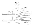
- FIG. 1is a longitudinal side view of a mid-shaft region of a catheter assembly which is representative of a PRIOR ART assembly.
- FIG. 2is a longitudinal side view of an embodiment of the invention.
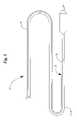
- FIG. 3is a perspective side view of a hypotube configuration suitable for use in the embodiment shown in FIG. 2 .
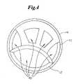
- FIG. 4is a cross-sectional view of the embodiment shown in FIG. 2
- FIG. 5is a side elevational view of a balloon dilatation catheter with the embodiment of FIG. 2 .
- FIG. 6is a cross-sectional view of the embodiment shown in FIG. 2 with a butt-weld engagement between the outer shaft and the coating.
- FIG. 1shows a longitudinal cross-section of a PRIOR ART catheter assembly 100 , which employs a mid-shaft tube 110 to connect the proximal shaft or hypotube 112 and distal outer 114 .
- the mid-shaft tube 110is welded, bonded or otherwise engaged to the proximal shaft 112 via a polymeric coating 117 .
- the mid-shaft tube 110supports the inner shaft 122 which defines a proximal guide wire lumen 124 .
- a core wire 120extends through an inflation lumen 126 defined by the hypotube 112 to provide further support and reinforcement of the port bond 118 of the mid-shaft region shown.
- a catheter assemblyis assembled without employing a mid-shaft tube and/or a core wire such as previously described.
- the catheter assemblymay be a balloon catheter 10 , as illustrated in FIG. 5 .
- a proximal shaft or hypotube 12includes a sheath or coating 14 of one or more polymeric materials such as polyesters; polyurethanes; polyamides; polyolefins including polyethylene and polypropylene; and any copolymers thereof.
- polymeric materialssuch as polyesters; polyurethanes; polyamides; polyolefins including polyethylene and polypropylene; and any copolymers thereof.
- suitable materialsinclude, but are not limited to: nylon; polyester elastomer; polyether/block polyamide, such as Pebax, Hytrel, and/or Arnitel; polyamid such as Grilamid; flouro-polymer, such as Kynar; polyether ether ketone (PEEK); polyethylene (PE); polyurethane; polyolefin copolymer (POC); tetrafluoroethylenes, such as polytetrafluoroethylene (PTFE); etc.
- Coating 14may be applied to the external surface 16 of at least a portion of the hypotube 12 , or may be a tubular member of material disposed thereabout.
- the hypotube 12is at least partially constructed from one or more non-thermoplastic polymers and/or metal.
- at least one side, of the distal end, of the hypotube 12is engaged to the interior surface 22 of the distal outer shaft 20 , in an overlapping configuration.
- the coating 14is welded or otherwise bonded to the distal outer shaft 20 .
- the coating 14may form a continuous polymeric layer of material with the distal outer shaft 20 .
- the distal outer shaft 20radially overlaps at least a portion of the coating 14 , or alternatively the coating 14 radially overlaps at least a portion of the distal outer shaft 20 .
- an end-to-end (butt-weld) engagement configuration ( 48 )is provided between the outer shaft 20 and the coating 14 , as shown in FIG. 6 .
- the catheter assembly 10has three engagement regions 42 , 44 and 46 .
- the engagement of the hypotube 12 and the distal outer shaft 20forms a first engagement region 42 .
- the engagement of the hypotube 12 and the inner shaft 24forms a second engagement region 44 .
- the engagement of the inner shaft 24 and the outer shaft 20forms a third engagement region 46 .
- the coating 14may act as a lubricious polymer shrinkable tube that is suitable for thermal welding of polymers of the adjacent structures.
- the hypotube 12is at least partially constructed of one or more metals such as stainless steel, titanium, nickel, and/or alloys thereof.
- the distal end of the hypotube 12may extend beyond the region where the distal outer is bonded to the hypotube 12 via coating 14 to provide greater radial support to the port bond 18 and push strength to the catheter 10 . Because only a portion of the hypotube 12 is bonded to the distal outer shaft 20 as previously described, flexibility of the port bond region is enhanced.
- the coating 14similarly provides for direct engagement of the inner shaft 24 to at least one side of the hypotube 12 as well.
- the inner shaft 24defines a lumen 26 through which a guide wire 28 is passed.
- Inner shaft 24also defines the port 29 where the guide wire 28 exits the catheter 10 .
- the coated hypotube 12may be directly engaged to the distal outer tube 20 by welding, bonding, physical engagement, or other engagement method(s) without the need of a mandrel or other support member.
- the hypotube 12is provided with sides 30 and 32 which are of equal or unequal length. Where one side 32 of the hypotube 12 is longer than other side 30 , the longer side 32 acts in place of the core wire to provide strain relief. As a result, the use of a core wire, such as has been previously described, is avoided in the present invention. As is shown in the embodiment depicted in FIG. 3 , at least a portion of the hypotube 12 may be provided with one or more indentations, spaces or cuts 34 in a spiral, helical or other geometric configuration. By providing the hypotube 12 with a spiral cut 34 strain relief as well as flexibility is further enhanced.
- hypotube 12As the distal end of the hypotube 12 advances through the port bond 18 of the catheter the hypotube 12 is deformed or otherwise provided with a more elliptical cross-sectional shape, such as is shown in FIG. 4 .
- the unique curvature of the hypotube 12 where it extends through the port bondallows the hypotube 12 to act as a supportive bridge or keystone in an arch to provide significant compression resistance to prevent collapse of the inflation lumen(s) 40 .
- any dependent claim which followsshould be taken as alternatively written in a multiple dependent form from all prior claims which possess all antecedents referenced in such dependent claim if such multiple dependent format is an accepted format within the jurisdiction (e.g. each claim depending directly from claim 1 should be alternatively taken as depending from all previous claims).
- each claim depending directly from claim 1should be alternatively taken as depending from all previous claims.
- the following dependent claimsshould each be also taken as alternatively written in each singly dependent claim format which creates a dependency from a prior antecedent-possessing claim other than the specific claim listed in such dependent claim below.
Landscapes
- Health & Medical Sciences (AREA)
- Life Sciences & Earth Sciences (AREA)
- Heart & Thoracic Surgery (AREA)
- Anesthesiology (AREA)
- Hematology (AREA)
- Biophysics (AREA)
- Pulmonology (AREA)
- Engineering & Computer Science (AREA)
- Veterinary Medicine (AREA)
- Biomedical Technology (AREA)
- Public Health (AREA)
- Animal Behavior & Ethology (AREA)
- General Health & Medical Sciences (AREA)
- Child & Adolescent Psychology (AREA)
- Vascular Medicine (AREA)
- Physics & Mathematics (AREA)
- Geometry (AREA)
- Materials For Medical Uses (AREA)
- Media Introduction/Drainage Providing Device (AREA)
Abstract
Description
Claims (23)
Priority Applications (8)
| Application Number | Priority Date | Filing Date | Title |
|---|---|---|---|
| US10/664,132US7367967B2 (en) | 2003-09-17 | 2003-09-17 | Catheter with sheathed hypotube |
| DE602004018793TDE602004018793D1 (en) | 2003-09-17 | 2004-07-23 | CATHETER WITH HYPOROLE WITH SLEEVE |
| ES04779044TES2319301T3 (en) | 2003-09-17 | 2004-07-23 | HIPOTUBE CATHETER WITH SHEATH. |
| AT04779044TATE419032T1 (en) | 2003-09-17 | 2004-07-23 | CATHETER WITH HYPOTUBE WITH SLEEVE |
| PCT/US2004/023809WO2005035044A1 (en) | 2003-09-17 | 2004-07-23 | Catheter with sheathed hypotube |
| JP2006526876AJP4637104B2 (en) | 2003-09-17 | 2004-07-23 | Catheter with coated hypotube |
| CA2531897ACA2531897C (en) | 2003-09-17 | 2004-07-23 | Catheter with sheathed hypotube |
| EP04779044AEP1663378B1 (en) | 2003-09-17 | 2004-07-23 | Catheter with sheathed hypotube |
Applications Claiming Priority (1)
| Application Number | Priority Date | Filing Date | Title |
|---|---|---|---|
| US10/664,132US7367967B2 (en) | 2003-09-17 | 2003-09-17 | Catheter with sheathed hypotube |
Publications (2)
| Publication Number | Publication Date |
|---|---|
| US20050059959A1 US20050059959A1 (en) | 2005-03-17 |
| US7367967B2true US7367967B2 (en) | 2008-05-06 |
Family
ID=34274525
Family Applications (1)
| Application Number | Title | Priority Date | Filing Date |
|---|---|---|---|
| US10/664,132Expired - LifetimeUS7367967B2 (en) | 2003-09-17 | 2003-09-17 | Catheter with sheathed hypotube |
Country Status (8)
| Country | Link |
|---|---|
| US (1) | US7367967B2 (en) |
| EP (1) | EP1663378B1 (en) |
| JP (1) | JP4637104B2 (en) |
| AT (1) | ATE419032T1 (en) |
| CA (1) | CA2531897C (en) |
| DE (1) | DE602004018793D1 (en) |
| ES (1) | ES2319301T3 (en) |
| WO (1) | WO2005035044A1 (en) |
Cited By (22)
| Publication number | Priority date | Publication date | Assignee | Title |
|---|---|---|---|---|
| US20080281229A1 (en)* | 2007-04-23 | 2008-11-13 | Juan Carlos Parodi | Guidewire with adjustable stiffness |
| US20090054874A1 (en)* | 2007-08-23 | 2009-02-26 | C. R. Bard, Inc. | Multi-lumen catheter including a lumen having a variable cross sectional area |
| US20100217234A1 (en)* | 2009-02-20 | 2010-08-26 | Boston Scientific Scimed, Inc. | Catheter With Skived Tubular Member |
| US20100217374A1 (en)* | 2009-02-20 | 2010-08-26 | Boston Scientific Scimed, Inc. | Torqueable Balloon Catheter |
| US20100305475A1 (en)* | 2007-04-23 | 2010-12-02 | Hinchliffe Peter W J | Guidewire with adjustable stiffness |
| US20110009942A1 (en)* | 2009-02-20 | 2011-01-13 | Boston Scientific Scimed, Inc. | Balloon catheter |
| USD684258S1 (en)* | 2012-03-29 | 2013-06-11 | Biotronik Ag | Hypotube hub |
| CN103313750A (en)* | 2010-10-20 | 2013-09-18 | 斯瑞克公司 | Stent delivery catheter with rapid exchange capabilities |
| US20150005803A1 (en)* | 2012-03-23 | 2015-01-01 | Terumo Kabushiki Kaisha | Balloon catheter |
| US9079000B2 (en) | 2011-10-18 | 2015-07-14 | Boston Scientific Scimed, Inc. | Integrated crossing balloon catheter |
| US9332999B2 (en) | 2012-08-13 | 2016-05-10 | Covidien Lp | Apparatus and methods for clot disruption and evacuation |
| US9332998B2 (en) | 2012-08-13 | 2016-05-10 | Covidien Lp | Apparatus and methods for clot disruption and evacuation |
| US10617847B2 (en) | 2014-11-04 | 2020-04-14 | Orbusneich Medical Pte. Ltd. | Variable flexibility catheter support frame |
| US10888354B2 (en)* | 2006-11-21 | 2021-01-12 | Bridgepoint Medical, Inc. | Endovascular devices and methods for exploiting intramural space |
| US11364363B2 (en) | 2016-12-08 | 2022-06-21 | Abiomed, Inc. | Overmold technique for peel-away introducer design |
| US11793977B2 (en) | 2018-05-16 | 2023-10-24 | Abiomed, Inc. | Peel-away sheath assembly |
| US11839722B2 (en) | 2014-11-04 | 2023-12-12 | Orbusneich Medical Pte. Ltd. | Progressive flexibility catheter support frame |
| US12274497B2 (en) | 2019-12-18 | 2025-04-15 | Bolt Medical, Inc. | Multiplexer for laser-driven intravascular lithotripsy device |
| US12274485B2 (en) | 2021-01-12 | 2025-04-15 | Bolt Medical, Inc. | Balloon assembly for valvuloplasty catheter system |
| US12280223B2 (en) | 2019-06-26 | 2025-04-22 | Boston Scientific Scimed, Inc. | Focusing element for plasma system to disrupt vascular lesions |
| US12295654B2 (en) | 2020-06-03 | 2025-05-13 | Boston Scientific Scimed, Inc. | System and method for maintaining balloon integrity within intravascular lithotripsy device with plasma generator |
| US12402946B2 (en) | 2019-06-19 | 2025-09-02 | Boston Scientific Scimed, Inc. | Breakdown of laser pulse energy for breakup of vascular calcium |
Families Citing this family (10)
| Publication number | Priority date | Publication date | Assignee | Title |
|---|---|---|---|---|
| WO2008088766A1 (en)* | 2002-03-22 | 2008-07-24 | Cordis Corporation | Rapid-exchange balloon catheter shaft and method |
| US8252014B2 (en) | 2004-03-03 | 2012-08-28 | Innovational Holdings Llc. | Rapid exchange balloon catheter with braided shaft |
| US20060229657A1 (en)* | 2005-03-30 | 2006-10-12 | Wasicek Lawrence D | Single operator exchange embolic protection filter |
| EP2244775B1 (en)* | 2007-12-26 | 2018-02-28 | Cook Medical Technologies LLC | Deployment catheter and delivery system thereof |
| US20090209941A1 (en)* | 2008-02-19 | 2009-08-20 | William Cook Europe, Aps | Implant deployment catheter |
| US9211389B2 (en) | 2009-12-07 | 2015-12-15 | Cook Medical Technologies Llc | Offset soft tip with proposed tooling |
| JP5614773B2 (en)* | 2011-02-15 | 2014-10-29 | 朝日インテック株式会社 | Balloon catheter |
| EP3275495A4 (en)* | 2015-03-25 | 2018-12-05 | Olympus Corporation | Treatment instrument |
| JP6831366B2 (en)* | 2016-03-16 | 2021-02-17 | テルモ株式会社 | Method for manufacturing balloon catheter and long member for balloon catheter |
| CN110461403B (en)* | 2017-03-31 | 2022-07-29 | 泰尔茂株式会社 | Balloon catheter and method for producing medical elongated body |
Citations (49)
| Publication number | Priority date | Publication date | Assignee | Title |
|---|---|---|---|---|
| US4251305A (en) | 1978-11-01 | 1981-02-17 | Baxter Travenol Laboratories, Inc. | Method of radiant heat sealing of a balloon onto a catheter employing tinted shrink tubing |
| US4636272A (en) | 1985-02-19 | 1987-01-13 | Cordis Corporation | Process for thermally bonding plastic tubes |
| US4943278A (en) | 1988-02-29 | 1990-07-24 | Scimed Life Systems, Inc. | Dilatation balloon catheter |
| US4964409A (en) | 1989-05-11 | 1990-10-23 | Advanced Cardiovascular Systems, Inc. | Flexible hollow guiding member with means for fluid communication therethrough |
| US5046497A (en) | 1986-11-14 | 1991-09-10 | Millar Instruments, Inc. | Structure for coupling a guidewire and a catheter |
| US5047045A (en) | 1989-04-13 | 1991-09-10 | Scimed Life Systems, Inc. | Multi-section coaxial angioplasty catheter |
| US5100381A (en) | 1989-11-13 | 1992-03-31 | Scimed Life Systems, Inc. | Angioplasty catheter |
| US5154725A (en) | 1991-06-07 | 1992-10-13 | Advanced Cardiovascular Systems, Inc. | Easily exchangeable catheter system |
| US5156594A (en) | 1990-08-28 | 1992-10-20 | Scimed Life Systems, Inc. | Balloon catheter with distal guide wire lumen |
| US5261879A (en) | 1992-09-03 | 1993-11-16 | Scimed Life Systems, Inc. | Coaxial/side-by-side lumen perfusion dilatation catheter |
| US5279562A (en) | 1991-07-24 | 1994-01-18 | Advanced Cardiovascular Systems, Inc. | Low profile perfusion-type dilatation catheter |
| US5281203A (en) | 1991-07-05 | 1994-01-25 | Scimed Life Systems, Inc. | Guide wire and sheath for single operator exchange |
| US5295961A (en) | 1991-06-03 | 1994-03-22 | Schneider (Europe) A.G. | Catheter system for mechanical dilatation of coronary stenoses |
| US5304134A (en) | 1992-01-17 | 1994-04-19 | Danforth Biomedical, Inc. | Lubricious yet bondable catheter channel sleeve for over-the-wire catheters |
| US5306247A (en) | 1991-12-11 | 1994-04-26 | Schneider (Europe) A.G. | Balloon catheter |
| US5383853A (en) | 1992-11-12 | 1995-01-24 | Medtronic, Inc. | Rapid exchange catheter |
| US5387193A (en) | 1994-02-09 | 1995-02-07 | Baxter International Inc. | Balloon dilation catheter with hypotube |
| US5395334A (en) | 1990-08-28 | 1995-03-07 | Scimed Life Systems, Inc. | Balloon catheter with distal guide wire lumen |
| US5397306A (en) | 1989-12-20 | 1995-03-14 | Terumo Kabushiki Kaisha | Catheter |
| US5480383A (en) | 1994-05-27 | 1996-01-02 | Advanced Cardiovascular Systems, Inc. | Dilation catheter with a smooth transition between a stiff proximal portion and a flexible distal portion |
| US5490837A (en) | 1991-07-05 | 1996-02-13 | Scimed Life Systems, Inc. | Single operator exchange catheter having a distal catheter shaft section |
| US5549556A (en) | 1992-11-19 | 1996-08-27 | Medtronic, Inc. | Rapid exchange catheter with external wire lumen |
| US5549552A (en) | 1995-03-02 | 1996-08-27 | Scimed Life Systems, Inc. | Balloon dilation catheter with improved pushability, trackability and crossability |
| US5567203A (en) | 1988-02-29 | 1996-10-22 | Scimed Life Systems, Inc. | Balloon dilatation catheter with proximal hypotube |
| US5976107A (en) | 1991-07-05 | 1999-11-02 | Scimed Life Systems. Inc. | Catheter having extendable guide wire lumen |
| US5980484A (en) | 1993-04-29 | 1999-11-09 | Scimed Life Systems, Inc. | Dilation balloon for a single operator exchange catheter or similar device |
| US6102890A (en) | 1998-10-23 | 2000-08-15 | Scimed Life Systems, Inc. | Catheter having improved proximal shaft design |
| US6129708A (en) | 1989-01-30 | 2000-10-10 | Medtronic Ave, Inc. | Rapidly exchangeable coronary catheter |
| US6179810B1 (en) | 1999-08-17 | 2001-01-30 | Advanced Cardiovascular Systems, Inc. | Catheter with a flexible and pushable shaft |
| US6193686B1 (en) | 1999-06-30 | 2001-02-27 | Advanced Cardiovascular Systems, Inc. | Catheter with enhanced flexibility |
| US6238376B1 (en) | 1997-03-18 | 2001-05-29 | Advanced Cardiovascular Systems, Inc. | Bonding a polymer member to a metallic member |
| US6319229B1 (en) | 1998-02-19 | 2001-11-20 | Medtronic Percusurge, Inc. | Balloon catheter and method of manufacture |
| WO2001089621A1 (en) | 2000-05-23 | 2001-11-29 | Advanced Cardiovascular Systems, Inc. | Catheter with improved transition |
| US6361529B1 (en) | 1998-09-09 | 2002-03-26 | Schneider (Usa) Inc. | Stiffening member in a rapid exchange dilation catheter |
| US6398799B2 (en) | 1991-06-11 | 2002-06-04 | Advanced Cardiovascular Systems, Inc. | Catheter system with catheter and guidewire exchange |
| US6458099B2 (en) | 1999-12-17 | 2002-10-01 | Advanced Cardiovascular Systems, Inc. | Catheters having rapid-exchange and over-the-wire operating modes |
| US6458867B1 (en) | 1999-09-28 | 2002-10-01 | Scimed Life Systems, Inc. | Hydrophilic lubricant coatings for medical devices |
| US6461347B1 (en) | 1997-03-06 | 2002-10-08 | Progenix, Llc | Low profile catheter shaft |
| US6475187B1 (en) | 1998-03-04 | 2002-11-05 | Scimed Life Systems, Inc. | Convertible catheter incorporating distal force transfer mechanism |
| US6488655B1 (en) | 1999-06-30 | 2002-12-03 | Advanced Cardiovascular Systems, Inc. | Polymer jacket with adhesive inner layer |
| US6503223B1 (en) | 1998-03-18 | 2003-01-07 | Nippon Zeon Co., Ltd. | Balloon catheter |
| US6520951B1 (en) | 1996-09-13 | 2003-02-18 | Scimed Life Systems, Inc. | Rapid exchange catheter with detachable hood |
| US6548010B1 (en) | 2000-03-23 | 2003-04-15 | Scimed Life Systems, Inc. | Transition region for an intravascular catheter |
| US6558401B1 (en) | 1998-08-04 | 2003-05-06 | Medtronic Percusurge, Inc. | Low profile catheter for angioplasty and occlusion |
| WO2003037418A2 (en) | 2001-11-01 | 2003-05-08 | Advanced Cardiovascular Systems, Inc. | Catheter having improved rapid exchange junction |
| US6589207B1 (en) | 1999-12-21 | 2003-07-08 | Advanced Cardiovascular Systems, Inc. | Rapid exchange catheter having a support mandrel |
| US6605062B1 (en) | 1999-09-02 | 2003-08-12 | Advanced Cardiovascular Systems, Inc. | Catheter for guidewire support or exchange |
| US6605057B2 (en) | 1996-10-24 | 2003-08-12 | Medtronic Ave, Inc. | Reinforced monorail balloon catheter |
| US6613066B1 (en) | 1998-10-05 | 2003-09-02 | Kaneka Corporation | Balloon catheter and production method therefor |
- 2003
- 2003-09-17USUS10/664,132patent/US7367967B2/ennot_activeExpired - Lifetime
- 2004
- 2004-07-23WOPCT/US2004/023809patent/WO2005035044A1/enactiveApplication Filing
- 2004-07-23EPEP04779044Apatent/EP1663378B1/ennot_activeExpired - Lifetime
- 2004-07-23DEDE602004018793Tpatent/DE602004018793D1/ennot_activeExpired - Lifetime
- 2004-07-23ATAT04779044Tpatent/ATE419032T1/ennot_activeIP Right Cessation
- 2004-07-23ESES04779044Tpatent/ES2319301T3/ennot_activeExpired - Lifetime
- 2004-07-23JPJP2006526876Apatent/JP4637104B2/ennot_activeExpired - Fee Related
- 2004-07-23CACA2531897Apatent/CA2531897C/ennot_activeExpired - Fee Related
Patent Citations (59)
| Publication number | Priority date | Publication date | Assignee | Title |
|---|---|---|---|---|
| US4251305A (en) | 1978-11-01 | 1981-02-17 | Baxter Travenol Laboratories, Inc. | Method of radiant heat sealing of a balloon onto a catheter employing tinted shrink tubing |
| US4636272A (en) | 1985-02-19 | 1987-01-13 | Cordis Corporation | Process for thermally bonding plastic tubes |
| US5046497A (en) | 1986-11-14 | 1991-09-10 | Millar Instruments, Inc. | Structure for coupling a guidewire and a catheter |
| US4943278A (en) | 1988-02-29 | 1990-07-24 | Scimed Life Systems, Inc. | Dilatation balloon catheter |
| US5567203A (en) | 1988-02-29 | 1996-10-22 | Scimed Life Systems, Inc. | Balloon dilatation catheter with proximal hypotube |
| US6129708A (en) | 1989-01-30 | 2000-10-10 | Medtronic Ave, Inc. | Rapidly exchangeable coronary catheter |
| US5047045A (en) | 1989-04-13 | 1991-09-10 | Scimed Life Systems, Inc. | Multi-section coaxial angioplasty catheter |
| US5370655A (en) | 1989-04-13 | 1994-12-06 | Scimed Life Systems, Inc. | Angioplasty catheter |
| US4964409A (en) | 1989-05-11 | 1990-10-23 | Advanced Cardiovascular Systems, Inc. | Flexible hollow guiding member with means for fluid communication therethrough |
| US5100381A (en) | 1989-11-13 | 1992-03-31 | Scimed Life Systems, Inc. | Angioplasty catheter |
| US5397306A (en) | 1989-12-20 | 1995-03-14 | Terumo Kabushiki Kaisha | Catheter |
| US5370616A (en) | 1990-08-28 | 1994-12-06 | Scimed Life Systems, Inc. | Balloon catheter with disial guide wire lumen |
| US6273879B1 (en) | 1990-08-28 | 2001-08-14 | Scimed Life Systems Inc | Balloon catheter with distal guide wire lumen |
| US5522818A (en) | 1990-08-28 | 1996-06-04 | Scimed Life Systems, Inc. | Balloon catheter with distal guide wire lumen |
| US5702439A (en)* | 1990-08-28 | 1997-12-30 | Scimed Life Systems, Inc. | Balloon catheter with distal guide wire lumen |
| US5395334A (en) | 1990-08-28 | 1995-03-07 | Scimed Life Systems, Inc. | Balloon catheter with distal guide wire lumen |
| US5156594A (en) | 1990-08-28 | 1992-10-20 | Scimed Life Systems, Inc. | Balloon catheter with distal guide wire lumen |
| US5295961A (en) | 1991-06-03 | 1994-03-22 | Schneider (Europe) A.G. | Catheter system for mechanical dilatation of coronary stenoses |
| US5154725A (en) | 1991-06-07 | 1992-10-13 | Advanced Cardiovascular Systems, Inc. | Easily exchangeable catheter system |
| US5346505A (en) | 1991-06-07 | 1994-09-13 | Advanced Cardiovascular Systems, Inc. | Easily exchangeable catheter system |
| US6398799B2 (en) | 1991-06-11 | 2002-06-04 | Advanced Cardiovascular Systems, Inc. | Catheter system with catheter and guidewire exchange |
| US5976107A (en) | 1991-07-05 | 1999-11-02 | Scimed Life Systems. Inc. | Catheter having extendable guide wire lumen |
| US5281203A (en) | 1991-07-05 | 1994-01-25 | Scimed Life Systems, Inc. | Guide wire and sheath for single operator exchange |
| US5490837A (en) | 1991-07-05 | 1996-02-13 | Scimed Life Systems, Inc. | Single operator exchange catheter having a distal catheter shaft section |
| US5279562A (en) | 1991-07-24 | 1994-01-18 | Advanced Cardiovascular Systems, Inc. | Low profile perfusion-type dilatation catheter |
| US5306247A (en) | 1991-12-11 | 1994-04-26 | Schneider (Europe) A.G. | Balloon catheter |
| US5304134A (en) | 1992-01-17 | 1994-04-19 | Danforth Biomedical, Inc. | Lubricious yet bondable catheter channel sleeve for over-the-wire catheters |
| US5261879A (en) | 1992-09-03 | 1993-11-16 | Scimed Life Systems, Inc. | Coaxial/side-by-side lumen perfusion dilatation catheter |
| US5383853A (en) | 1992-11-12 | 1995-01-24 | Medtronic, Inc. | Rapid exchange catheter |
| US5549556A (en) | 1992-11-19 | 1996-08-27 | Medtronic, Inc. | Rapid exchange catheter with external wire lumen |
| US5980484A (en) | 1993-04-29 | 1999-11-09 | Scimed Life Systems, Inc. | Dilation balloon for a single operator exchange catheter or similar device |
| US5439447A (en) | 1994-02-09 | 1995-08-08 | Baxter International Inc. | Balloon dilation catheter with hypotube |
| US5387193A (en) | 1994-02-09 | 1995-02-07 | Baxter International Inc. | Balloon dilation catheter with hypotube |
| US5480383A (en) | 1994-05-27 | 1996-01-02 | Advanced Cardiovascular Systems, Inc. | Dilation catheter with a smooth transition between a stiff proximal portion and a flexible distal portion |
| US5549552A (en) | 1995-03-02 | 1996-08-27 | Scimed Life Systems, Inc. | Balloon dilation catheter with improved pushability, trackability and crossability |
| US6520951B1 (en) | 1996-09-13 | 2003-02-18 | Scimed Life Systems, Inc. | Rapid exchange catheter with detachable hood |
| US6605057B2 (en) | 1996-10-24 | 2003-08-12 | Medtronic Ave, Inc. | Reinforced monorail balloon catheter |
| US6461347B1 (en) | 1997-03-06 | 2002-10-08 | Progenix, Llc | Low profile catheter shaft |
| US6238376B1 (en) | 1997-03-18 | 2001-05-29 | Advanced Cardiovascular Systems, Inc. | Bonding a polymer member to a metallic member |
| US6319229B1 (en) | 1998-02-19 | 2001-11-20 | Medtronic Percusurge, Inc. | Balloon catheter and method of manufacture |
| US6475187B1 (en) | 1998-03-04 | 2002-11-05 | Scimed Life Systems, Inc. | Convertible catheter incorporating distal force transfer mechanism |
| US6503223B1 (en) | 1998-03-18 | 2003-01-07 | Nippon Zeon Co., Ltd. | Balloon catheter |
| US6558401B1 (en) | 1998-08-04 | 2003-05-06 | Medtronic Percusurge, Inc. | Low profile catheter for angioplasty and occlusion |
| US6361529B1 (en) | 1998-09-09 | 2002-03-26 | Schneider (Usa) Inc. | Stiffening member in a rapid exchange dilation catheter |
| US6613066B1 (en) | 1998-10-05 | 2003-09-02 | Kaneka Corporation | Balloon catheter and production method therefor |
| US6387075B1 (en) | 1998-10-23 | 2002-05-14 | Scimed Life Systems, Inc. | Catheter having improved proximal shaft design |
| US6102890A (en) | 1998-10-23 | 2000-08-15 | Scimed Life Systems, Inc. | Catheter having improved proximal shaft design |
| US6193686B1 (en) | 1999-06-30 | 2001-02-27 | Advanced Cardiovascular Systems, Inc. | Catheter with enhanced flexibility |
| US6488655B1 (en) | 1999-06-30 | 2002-12-03 | Advanced Cardiovascular Systems, Inc. | Polymer jacket with adhesive inner layer |
| US20020038103A1 (en) | 1999-06-30 | 2002-03-28 | Advanced Cardiovascular Systems, Inc. | Catheter with enhanced flexibility |
| US6179810B1 (en) | 1999-08-17 | 2001-01-30 | Advanced Cardiovascular Systems, Inc. | Catheter with a flexible and pushable shaft |
| US6605062B1 (en) | 1999-09-02 | 2003-08-12 | Advanced Cardiovascular Systems, Inc. | Catheter for guidewire support or exchange |
| US6458867B1 (en) | 1999-09-28 | 2002-10-01 | Scimed Life Systems, Inc. | Hydrophilic lubricant coatings for medical devices |
| US6458099B2 (en) | 1999-12-17 | 2002-10-01 | Advanced Cardiovascular Systems, Inc. | Catheters having rapid-exchange and over-the-wire operating modes |
| US6589207B1 (en) | 1999-12-21 | 2003-07-08 | Advanced Cardiovascular Systems, Inc. | Rapid exchange catheter having a support mandrel |
| US6548010B1 (en) | 2000-03-23 | 2003-04-15 | Scimed Life Systems, Inc. | Transition region for an intravascular catheter |
| WO2001089621A1 (en) | 2000-05-23 | 2001-11-29 | Advanced Cardiovascular Systems, Inc. | Catheter with improved transition |
| US6575958B1 (en) | 2000-05-23 | 2003-06-10 | Advanced Cardiovascular Systems, Inc. | Catheter with improved transition |
| WO2003037418A2 (en) | 2001-11-01 | 2003-05-08 | Advanced Cardiovascular Systems, Inc. | Catheter having improved rapid exchange junction |
Cited By (37)
| Publication number | Priority date | Publication date | Assignee | Title |
|---|---|---|---|---|
| US10888354B2 (en)* | 2006-11-21 | 2021-01-12 | Bridgepoint Medical, Inc. | Endovascular devices and methods for exploiting intramural space |
| US20080281228A1 (en)* | 2007-04-23 | 2008-11-13 | Juan Carlos Parodi | Guidewire with adjustable stiffness |
| US20090143768A1 (en)* | 2007-04-23 | 2009-06-04 | Interventional & Surgical Innovations, Llc | Guidewire with adjustable stiffness |
| US9498603B2 (en) | 2007-04-23 | 2016-11-22 | Cardioguidance Biomedical, Llc | Guidewire with adjustable stiffness |
| US9387309B2 (en) | 2007-04-23 | 2016-07-12 | Cardioguidance Biomedical, Llc | Guidewire with adjustable stiffness |
| US20100305475A1 (en)* | 2007-04-23 | 2010-12-02 | Hinchliffe Peter W J | Guidewire with adjustable stiffness |
| US9387308B2 (en) | 2007-04-23 | 2016-07-12 | Cardioguidance Biomedical, Llc | Guidewire with adjustable stiffness |
| US10258773B2 (en) | 2007-04-23 | 2019-04-16 | Cardioguidance Biomedical, Llc | Guidewire with adjustable stiffness |
| US20080281229A1 (en)* | 2007-04-23 | 2008-11-13 | Juan Carlos Parodi | Guidewire with adjustable stiffness |
| US20090054874A1 (en)* | 2007-08-23 | 2009-02-26 | C. R. Bard, Inc. | Multi-lumen catheter including a lumen having a variable cross sectional area |
| US8512282B2 (en) | 2009-02-20 | 2013-08-20 | Boston Scientific Scimed, Inc. | Catheter with skived tubular member |
| US9011511B2 (en) | 2009-02-20 | 2015-04-21 | Boston Scientific Scimed, Inc. | Balloon catheter |
| US9687634B2 (en) | 2009-02-20 | 2017-06-27 | Boston Scientific Scimed, Inc. | Catheter with skived tubular member |
| US8057430B2 (en) | 2009-02-20 | 2011-11-15 | Boston Scientific Scimed, Inc. | Catheter with skived tubular member |
| US20110009942A1 (en)* | 2009-02-20 | 2011-01-13 | Boston Scientific Scimed, Inc. | Balloon catheter |
| US20100217374A1 (en)* | 2009-02-20 | 2010-08-26 | Boston Scientific Scimed, Inc. | Torqueable Balloon Catheter |
| US20100217234A1 (en)* | 2009-02-20 | 2010-08-26 | Boston Scientific Scimed, Inc. | Catheter With Skived Tubular Member |
| CN103313750A (en)* | 2010-10-20 | 2013-09-18 | 斯瑞克公司 | Stent delivery catheter with rapid exchange capabilities |
| CN103313750B (en)* | 2010-10-20 | 2015-08-19 | 斯瑞克公司 | There is the stent delivery catheter of rapid exchange capability |
| US9079000B2 (en) | 2011-10-18 | 2015-07-14 | Boston Scientific Scimed, Inc. | Integrated crossing balloon catheter |
| US20150005803A1 (en)* | 2012-03-23 | 2015-01-01 | Terumo Kabushiki Kaisha | Balloon catheter |
| US9364645B2 (en)* | 2012-03-23 | 2016-06-14 | Terumo Kabushiki Kaisha | Balloon catheter |
| USD684258S1 (en)* | 2012-03-29 | 2013-06-11 | Biotronik Ag | Hypotube hub |
| US9332998B2 (en) | 2012-08-13 | 2016-05-10 | Covidien Lp | Apparatus and methods for clot disruption and evacuation |
| US9332999B2 (en) | 2012-08-13 | 2016-05-10 | Covidien Lp | Apparatus and methods for clot disruption and evacuation |
| US9808266B2 (en) | 2012-08-13 | 2017-11-07 | Covidien Lp | Apparatus and methods for clot disruption and evacuation |
| US10617847B2 (en) | 2014-11-04 | 2020-04-14 | Orbusneich Medical Pte. Ltd. | Variable flexibility catheter support frame |
| US11839722B2 (en) | 2014-11-04 | 2023-12-12 | Orbusneich Medical Pte. Ltd. | Progressive flexibility catheter support frame |
| US12076497B2 (en) | 2016-12-08 | 2024-09-03 | Abiomed, Inc. | Overmold technique for peel-away introducer design |
| US11364363B2 (en) | 2016-12-08 | 2022-06-21 | Abiomed, Inc. | Overmold technique for peel-away introducer design |
| US11717640B2 (en) | 2016-12-08 | 2023-08-08 | Abiomed, Inc. | Overmold technique for peel-away introducer design |
| US11793977B2 (en) | 2018-05-16 | 2023-10-24 | Abiomed, Inc. | Peel-away sheath assembly |
| US12402946B2 (en) | 2019-06-19 | 2025-09-02 | Boston Scientific Scimed, Inc. | Breakdown of laser pulse energy for breakup of vascular calcium |
| US12280223B2 (en) | 2019-06-26 | 2025-04-22 | Boston Scientific Scimed, Inc. | Focusing element for plasma system to disrupt vascular lesions |
| US12274497B2 (en) | 2019-12-18 | 2025-04-15 | Bolt Medical, Inc. | Multiplexer for laser-driven intravascular lithotripsy device |
| US12295654B2 (en) | 2020-06-03 | 2025-05-13 | Boston Scientific Scimed, Inc. | System and method for maintaining balloon integrity within intravascular lithotripsy device with plasma generator |
| US12274485B2 (en) | 2021-01-12 | 2025-04-15 | Bolt Medical, Inc. | Balloon assembly for valvuloplasty catheter system |
Also Published As
| Publication number | Publication date |
|---|---|
| CA2531897A1 (en) | 2005-04-21 |
| US20050059959A1 (en) | 2005-03-17 |
| ES2319301T3 (en) | 2009-05-06 |
| JP4637104B2 (en) | 2011-02-23 |
| ATE419032T1 (en) | 2009-01-15 |
| JP2007505683A (en) | 2007-03-15 |
| EP1663378A1 (en) | 2006-06-07 |
| WO2005035044A1 (en) | 2005-04-21 |
| EP1663378B1 (en) | 2008-12-31 |
| DE602004018793D1 (en) | 2009-02-12 |
| CA2531897C (en) | 2012-09-25 |
Similar Documents
| Publication | Publication Date | Title |
|---|---|---|
| US7367967B2 (en) | Catheter with sheathed hypotube | |
| US6970734B2 (en) | Flexible marker bands | |
| US7273470B2 (en) | Catheter having improved rapid exchange junction | |
| EP1683540B1 (en) | Balloon Catheter having a soft distal tip | |
| US7195611B1 (en) | Rapid exchange balloon catheter having a reinforced inner tubular member | |
| EP1284779B1 (en) | Catheter with improved transition | |
| US8012300B2 (en) | Balloon catheter having a shaft with a variable stiffness inner tubular member | |
| US7488304B2 (en) | Covered hypotube to distal port bond | |
| US20030208221A1 (en) | Catheter with a coiled support member |
Legal Events
| Date | Code | Title | Description |
|---|---|---|---|
| AS | Assignment | Owner name:SCIMED LIFE SYSTEMS, INC., MINNESOTA Free format text:ASSIGNMENT OF ASSIGNORS INTEREST;ASSIGNOR:EIDENSCHINK, TRACEE;REEL/FRAME:014510/0124 Effective date:20030915 | |
| AS | Assignment | Owner name:BOSTON SCIENTIFIC SCIMED, INC., MINNESOTA Free format text:CHANGE OF NAME;ASSIGNOR:SCIMED LIFE SYSTEMS, INC.;REEL/FRAME:018505/0868 Effective date:20050101 Owner name:BOSTON SCIENTIFIC SCIMED, INC.,MINNESOTA Free format text:CHANGE OF NAME;ASSIGNOR:SCIMED LIFE SYSTEMS, INC.;REEL/FRAME:018505/0868 Effective date:20050101 | |
| FEPP | Fee payment procedure | Free format text:PAYOR NUMBER ASSIGNED (ORIGINAL EVENT CODE: ASPN); ENTITY STATUS OF PATENT OWNER: LARGE ENTITY | |
| STCF | Information on status: patent grant | Free format text:PATENTED CASE | |
| FPAY | Fee payment | Year of fee payment:4 | |
| FPAY | Fee payment | Year of fee payment:8 | |
| MAFP | Maintenance fee payment | Free format text:PAYMENT OF MAINTENANCE FEE, 12TH YEAR, LARGE ENTITY (ORIGINAL EVENT CODE: M1553); ENTITY STATUS OF PATENT OWNER: LARGE ENTITY Year of fee payment:12 |