US7367319B2 - Method and apparatus to determine magnitude of combustion chamber deposits - Google Patents
Method and apparatus to determine magnitude of combustion chamber depositsDownload PDFInfo
- Publication number
- US7367319B2 US7367319B2US11/399,194US39919406AUS7367319B2US 7367319 B2US7367319 B2US 7367319B2US 39919406 AUS39919406 AUS 39919406AUS 7367319 B2US7367319 B2US 7367319B2
- Authority
- US
- United States
- Prior art keywords
- combustion
- control system
- combustion chamber
- parameter
- engine
- Prior art date
- Legal status (The legal status is an assumption and is not a legal conclusion. Google has not performed a legal analysis and makes no representation as to the accuracy of the status listed.)
- Expired - Fee Related, expires
Links
Images


Classifications
- F—MECHANICAL ENGINEERING; LIGHTING; HEATING; WEAPONS; BLASTING
- F02—COMBUSTION ENGINES; HOT-GAS OR COMBUSTION-PRODUCT ENGINE PLANTS
- F02B—INTERNAL-COMBUSTION PISTON ENGINES; COMBUSTION ENGINES IN GENERAL
- F02B23/00—Other engines characterised by special shape or construction of combustion chambers to improve operation
- F02B23/02—Other engines characterised by special shape or construction of combustion chambers to improve operation with compression ignition
- F02B23/06—Other engines characterised by special shape or construction of combustion chambers to improve operation with compression ignition the combustion space being arranged in working piston
- F02B23/0672—Omega-piston bowl, i.e. the combustion space having a central projection pointing towards the cylinder head and the surrounding wall being inclined towards the cylinder center axis
- F—MECHANICAL ENGINEERING; LIGHTING; HEATING; WEAPONS; BLASTING
- F02—COMBUSTION ENGINES; HOT-GAS OR COMBUSTION-PRODUCT ENGINE PLANTS
- F02D—CONTROLLING COMBUSTION ENGINES
- F02D13/00—Controlling the engine output power by varying inlet or exhaust valve operating characteristics, e.g. timing
- F02D13/02—Controlling the engine output power by varying inlet or exhaust valve operating characteristics, e.g. timing during engine operation
- F02D13/0223—Variable control of the intake valves only
- F02D13/0234—Variable control of the intake valves only changing the valve timing only
- F—MECHANICAL ENGINEERING; LIGHTING; HEATING; WEAPONS; BLASTING
- F02—COMBUSTION ENGINES; HOT-GAS OR COMBUSTION-PRODUCT ENGINE PLANTS
- F02D—CONTROLLING COMBUSTION ENGINES
- F02D35/00—Controlling engines, dependent on conditions exterior or interior to engines, not otherwise provided for
- F02D35/02—Controlling engines, dependent on conditions exterior or interior to engines, not otherwise provided for on interior conditions
- F02D35/023—Controlling engines, dependent on conditions exterior or interior to engines, not otherwise provided for on interior conditions by determining the cylinder pressure
- F—MECHANICAL ENGINEERING; LIGHTING; HEATING; WEAPONS; BLASTING
- F02—COMBUSTION ENGINES; HOT-GAS OR COMBUSTION-PRODUCT ENGINE PLANTS
- F02D—CONTROLLING COMBUSTION ENGINES
- F02D35/00—Controlling engines, dependent on conditions exterior or interior to engines, not otherwise provided for
- F02D35/02—Controlling engines, dependent on conditions exterior or interior to engines, not otherwise provided for on interior conditions
- F02D35/025—Controlling engines, dependent on conditions exterior or interior to engines, not otherwise provided for on interior conditions by determining temperatures inside the cylinder, e.g. combustion temperatures
- F—MECHANICAL ENGINEERING; LIGHTING; HEATING; WEAPONS; BLASTING
- F02—COMBUSTION ENGINES; HOT-GAS OR COMBUSTION-PRODUCT ENGINE PLANTS
- F02D—CONTROLLING COMBUSTION ENGINES
- F02D35/00—Controlling engines, dependent on conditions exterior or interior to engines, not otherwise provided for
- F02D35/02—Controlling engines, dependent on conditions exterior or interior to engines, not otherwise provided for on interior conditions
- F02D35/028—Controlling engines, dependent on conditions exterior or interior to engines, not otherwise provided for on interior conditions by determining the combustion timing or phasing
- Y—GENERAL TAGGING OF NEW TECHNOLOGICAL DEVELOPMENTS; GENERAL TAGGING OF CROSS-SECTIONAL TECHNOLOGIES SPANNING OVER SEVERAL SECTIONS OF THE IPC; TECHNICAL SUBJECTS COVERED BY FORMER USPC CROSS-REFERENCE ART COLLECTIONS [XRACs] AND DIGESTS
- Y02—TECHNOLOGIES OR APPLICATIONS FOR MITIGATION OR ADAPTATION AGAINST CLIMATE CHANGE
- Y02T—CLIMATE CHANGE MITIGATION TECHNOLOGIES RELATED TO TRANSPORTATION
- Y02T10/00—Road transport of goods or passengers
- Y02T10/10—Internal combustion engine [ICE] based vehicles
- Y02T10/12—Improving ICE efficiencies
Definitions
- This inventionpertains generally to internal combustion engine control systems, and more specifically to operation of a homogeneous charge compression ignition engine.
- CCDcombustion chamber deposits
- the depositsare typically derived from fuels and fuel additives, lubricating oils and oil additives, and other elements, as is known.
- thermal characteristics of the enginechange. This is primarily due to the combustion chamber deposits acting as an insulating layer on the combustion chamber surfaces, which affects combustion.
- the result of the formation of the insulating layerincludes a decrease in maximum and average heat flux away from the combustion chamber, a decrease in heat transfer to engine coolant, and a decrease in engine breathability, i.e. air flow, leading to a reduced volumetric efficiency.
- the resultant effectsinclude reduced engine power, a potential for increase in NOx emissions, and an increased likelihood of pre-ignition, or knock. There may be a benefit of improved fuel economy and reduced CO 2 emissions.
- One engine system being developed for controlled auto-ignition combustion operationcomprises an internal combustion engine designed to operate under an Otto cycle.
- the engineis preferably equipped with direct in-cylinder fuel-injection and a spark ignition system to supplement the auto-ignition process under limited operating conditions.
- Such enginesare referred to as Homogeneous Charge Compression Ignition, or HCCI engines.
- HCCI engineIn the HCCI engine, a charge mixture of combusted gases, air, and fuel is created in a combustion chamber, and auto-ignition is initiated simultaneously from many ignition sites within the charge mixture during a compression stroke, resulting in stable power output and high thermal efficiency. Since combustion is highly diluted and uniformly distributed throughout the charge mixture, the burnt gas temperature and hence NOx emissions are typically substantially lower than NOx emissions of a traditional spark ignition engine, and of a traditional diesel engine.
- a typical HCCI engineis distinguishable from a spark-ignition engine in that ignition of the charge mixture is caused by compression of the charge mixture.
- a typical HCCI engineis distinguishable from a compression-ignition engine in that the compression-ignition engine initiates ignition of the combustion charge by injection of fuel, whereas the fuel charge for the typical HCCI engine is preferably injected into the combustion chamber at a time prior to start of ignition of the charge mixture.
- the present inventionrelates to an apparatus and method to dynamically determine a parametric value for combustion chamber deposits in a controlled auto-ignition engine.
- the key enablercomprises a method and apparatus for in-situ evaluation of thickness of combustion chamber deposits, based on a signal from a sensing device.
- a method and control systemcomprising a spark-ignition, four-stroke, internal combustion engine including a variable volume combustion chamber, wherein the control system is adapted to monitor a combustion parameter; and, determine a combustion chamber deposit parameter based upon the surface temperature characteristic or combustion parameter.
- An aspect of the inventionincludes the control system signally connected to a temperature sensing device operative to monitor temperature of a surface of the combustion chamber.
- the control systemis signally connected to a crank sensor, it is operable to determine the combustion chamber deposit parameter based upon an engine crank angle at which a peak combustion chamber surface temperature occurs during an engine cycle.
- Another aspect of the inventioncomprises the control system adapted to determine a combustion chamber deposit parameter, employing a pressure sensing device operative to determine an in-cylinder pressure parameter.
- the control systemis operable to determine the combustion chamber deposit parameter based upon crank angle location of a peak in-cylinder pressure parameter.
- Thiscan include an in-cylinder pressure sensor or a pressure sensor operatively connected external to the combustion chamber, e.g. a spark-plug device.
- a further aspect of the inventioncomprises the pressure sensing device operative to determine an in-cylinder pressure parameter, including crank angle location of a peak pressure, using a signal from a spark-ionization sensing device.
- Another aspect of the inventioncomprises a method and control system for an internal combustion engine operative in a controlled auto-ignition combustion mode that is adapted to monitor a combustion parameter, and determine a combustion chamber deposit parameter based upon the combustion parameter.
- FIG. 1is a schematic illustration of an internal combustion engine, in accordance with the present invention.
- FIG. 2is a schematic illustration of a detail of an internal combustion engine, in accordance with the present invention.
- FIGS. 3 , 4 , 5 , and 6comprise datagraphs, in accordance with the present invention.
- FIGS. 1 and 2comprise schematic diagrams of an internal combustion engine 10 and control system 25 which has been constructed in accordance with an embodiment of the present invention.
- the inventionis applied as an element of an overall control scheme for an internal combustion engine.
- the exemplary enginecomprises a multi-cylinder spark ignition, direct-injection, gasoline, four-stroke internal combustion engine adapted to operate under a controlled auto-ignition process, also referred to as homogenous-charge, compression-ignition (‘HCCI’).
- HCCIhomogenous-charge, compression-ignition
- the exemplary engine 10comprises: a cast-metal engine block with a plurality of cylinders formed therein, one of which is shown, and an engine head 27 .
- Each cylindercomprises a closed-end cylinder having a moveable, reciprocating piston 11 inserted therein.
- a variable volume combustion chamber 20is formed in each cylinder, and is defined by walls of the cylinder, the moveable piston 11 , and the head 27 .
- the engine blockpreferably includes coolant passages 29 through which engine coolant fluid passes.
- a coolant sensor 37operable to monitor temperature of the coolant fluid, is located at an appropriate location, and provides a parametric signal input to the control system 25 useable to control the engine.
- Each moveable piston 11comprises a device designed in accordance with known piston forming methods, and includes a top and a body which conform substantially to the cylinder in which it operates. The top area of the piston, or crown, is exposed in the combustion chamber.
- Each pistonis connected via a pin 34 and connecting rod 33 to a crankshaft 35 .
- the crankshaft 35is rotatably attached to the engine block at a main bearing area near a bottom portion of the engine block, such that the crankshaft is able to rotate around an axis that is perpendicular to a longitudinal axis defined by each cylinder.
- a crank sensor 31is placed in an appropriate location, operable to generate a signal that is useable by the controller 25 to measure crank angle, and which is translatable to provide measures of crankshaft rotation, speed, and acceleration that are useable in various control schemes.
- each piston 11moves up and down in the cylinder in a reciprocating fashion due to connection to and rotation of the crankshaft 35 and the combustion process.
- the rotation action of the crankshafteffects translation of linear force exerted on each piston during combustion to an angular torque output from the crankshaft, which can be transmitted to another device, e.g. a vehicle driveline.
- the engine head 27comprises a cast-metal device having one or more intake ports 17 and one or more exhaust ports 19 which flow to the combustion chamber 20 .
- the intake port 17supplies air to the combustion chamber 20 .
- Combusted (burned) gasesflow from the combustion chamber 20 via exhaust port 19 .
- Flow of air through each intake portis controlled by actuation of one or more intake valves 21 .
- Flow of combusted gases through each exhaust portis controlled by actuation of one or more exhaust valves 23 .
- a direct injection fuel injector 12 , spark plug 14 , and a combustion chamber deposit sensing device 16are each preferably mounted in the engine head, as described hereinbelow.
- the direct injection fuel injector 12 , spark plug 14 , and combustion chamber deposit sensing device 16are each signally and/or operatively connected to the control system 25 .
- the intake and exhaust valves 21 , 23each have a head portion that includes a top surface that is exposed to the combustion chamber.
- Each valve 21 , 23has a stem that is connected to a valve actuation device.
- Valve actuation devicescan comprise any one of a plurality of known devices that are operable to control timing, duration, and magnitude of opening and closing of each of the valves, either in concert, e.g. a camshaft, or separately using individual actuation devices, and are not described in detail herein.
- the valve actuation devicesare preferably operably controlled by the control system 25 according to known predetermined control schemes. Specific details of control schemes to control opening and closing of the valves are known and not detailed herein.
- Airis inlet to the intake port 17 through an intake manifold runner 50 , which receives filtered air passing through a known air metering device and a throttle device (not shown).
- Exhaust gaspasses from the exhaust port 19 to an exhaust manifold 42 , which includes exhaust gas sensors 40 operative to monitor constituents of the exhaust gas feedstream, and determine parameters associated therewith.
- the exhaust gas sensor 40can comprises any one of several known sensing devices operative to provide parametric values for the exhaust gas feedstream, including air/fuel ratio, exhaust gas constituents, e.g. NOx, CO, HC, and others.
- the aforementioned sensors and metering deviceseach provide a signal as a parametric input to the control system 25 . These parametric inputs can be used by the control system to determine combustion performance measurements.
- the control system 25preferably comprises a subset of an overall control architecture operable to provide coordinated system control of the engine 10 and other systems.
- the control system 25is operable to synthesize operator inputs, ambient conditions, engine operating parameters, and combustion performance measurements, and execute algorithms to control various actuators to achieve targets for control parameters, including such parameters as fuel economy, emissions, performance, and, driveability.
- the control system 25is operably connected to a plurality of devices through which an operator typically controls or directs operation of the engine. Exemplary operator inputs include an accelerator pedal, a brake pedal, transmission gear selector, and, vehicle speed cruise control when the engine is employed in a vehicle.
- the control systemmay communicate with other controllers, sensors, and actuators via a local area network (‘LAN’) bus (not shown) which preferably allows for structured communication of control parameters and commands between various controllers.
- LANlocal area network
- the control system 25is operably connected to the engine 10 , and functions to acquire parametric data from sensors, and control a variety of actuators, respectively, of the engine 10 over a plurality of discrete lines collectively shown as aggregate line 45
- the control system 25receives an engine torque command, and generates a desired torque output, based upon the operator inputs.
- Engine operating parametersthat are typically sensed by control system 25 using the aforementioned sensors include engine coolant temperature, crankshaft rotational speed (‘RPM’) and position, manifold absolute pressure, ambient air flow and temperature, and, ambient air pressure.
- Combustion performance measurementstypically comprise measured and inferred combustion parameters, including air/fuel ratio, location of peak combustion pressure (‘LPP’), amongst others.
- the control system 25preferably comprises a general-purpose digital computer generally comprising a microprocessor or central processing unit, read only memory (ROM), random access memory (RAM), electrically programmable read only memory (EPROM), high speed clock, analog to digital (AID) and digital to analog (D/A) circuitry, and input/output circuitry and devices (I/O) and appropriate signal conditioning and buffer circuitry.
- ROMread only memory
- RAMrandom access memory
- EPROMelectrically programmable read only memory
- high speed clockclock
- AIDanalog to digital
- D/Adigital to analog
- I/Oinput/output circuitry and devices
- Each controllerhas a set of control algorithms, comprising resident program instructions and calibrations stored in ROM and executed to provide the respective functions of each computer.
- Algorithms for engine controlare typically executed during preset loop cycles such that each algorithm is executed at least once each loop cycle.
- Algorithms stored in the non-volatile memory devicesare executed by the central processing unit and are operable to monitor inputs from the sensing devices and execute control and diagnostic routines to control operation of the engine, using preset calibrations.
- Loop cyclesare typically executed at regular intervals, for example each 3.125, 6.25, 12.5, 25 and 100 milliseconds during ongoing engine operation. Alternatively, algorithms may be executed in response to occurrence of an event.
- Combustion chamber deposit parameterscan be employed by an engine control system.
- An exemplary method and apparatus to control and operate an internal combustion engine using combustion chamber deposit parameteris disclosed in detail in commonly assigned U.S. patent application Ser. No. 11/398,776, entitled M ETHOD AND APPARATUS TO O PERATE A H OMOGENEOUS C HARGE C OMPRESSION -I GNITION E NGINE , which is incorporated herein by reference.
- the inventioncomprises a method and apparatus to operate an exemplary engine to compensate for effects of CCDs on combustion and overall engine operation.
- the inventioncomprises a method and a control system for the aforementioned internal combustion engine, wherein a combustion parameter is monitored, and a combustion chamber deposit parameter is determined based upon the monitored surface temperature characteristics or other combustion parameters.
- Monitoring the combustion parametercomprises the control system signally connected to one of several exemplary sensing devices 16 , described hereinbelow, which are operative to monitor parameters of the combustion chamber.
- the sensing device 16 to determine a parameter for CCDsincludes, for example, an in-cylinder device operable to detect changes in heat flux caused by a layer of deposits.
- the sensing devicecan comprise some form of in-cylinder pressure measurement.
- the sensing devicecan comprise a device to determine fluorescence of a thermo-sensitive coating on a wall of the combustion chamber.
- the sensing device 16comprises a temperature sensing device.
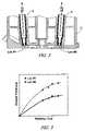
- FIG. 2is a schematic diagram showing the exemplary engine cylinder head 27 having a pair of exemplary temperature sensors 16 inserted therein, at two locations, Loc # 1 and Loc # 2 .
- Location of a temperature sensor in a specific combustion chamberis application-specific, with a location defined based upon an ability to accurately measure CCDs in the chamber and other factors.
- a given applicationmay have a single sensor for an engine, a single sensor for each cylinder, or multiple sensors for one or more cylinders, depending on factors outside the scope of the this invention.
- the temperature sensor 16comprises known fast-response coaxial J-type thermocouples used for measurement of instantaneous surface temperature and heat flux at the surface of the combustion chamber on the head 27 .
- Each sensoris mounted in the cylinder head so that a distal tip surface of the sensor is flush with the combustion chamber surface.
- the sensoris preferably attached to the end of long sleeves which are themselves mounted into the cylinder head.
- a tip surface of each sensor 16is exposed to combustion gases in the combustion chamber. Combustion chamber deposits are able to form on the end of the tip surface, thus affecting temperature monitoring performance of the sensor.
- CCD growth rateschange and the thickness on the tip surface varies, as depicted in FIG. 3 for Loc # 1 and Loc # 2 .
- the formation of CCD on the sensor tip surfacechanges the measured surface temperature profile, directly measurable in accordance with the level of CCD deposition on top of it.
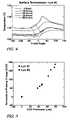
- FIGS. 4 and 5comprise exemplary datagraphs, derived experimentally using an experimental HCCI engine consistent with the engine described with reference to FIG. 1 , having the heat-flux sensors 16 as shown in FIG. 2 and as described hereinabove.
- FIG. 4there is shown a relationship between the magnitude of peak temperature and the phasing of peak temperature relative to engine crank angle (measured with the crank sensor 31 ) and CCD thickness at the tip surface, based on an analysis of a one-dimensional heat diffusion process.
- FIG. 5the datagraph demonstrates results of an analysis which shows a relationship between in-cylinder CCD formation and signal output from the sensor 16 .
- the sensor 16comprising the fast thermocouple device located in the cylinder head to obtain surface temperature measurements, can be used to monitor CCD thickness, based upon the relationship between phasing of the peak temperature and the CCD layer thickness, which can be the CCD input signal to the control system 25 .
- FIG. 6a data graph analogous to the data previously referenced with regard to FIGS. 4 and 5 , is shown.
- the results in FIG. 6demonstrate a change in location of peak cylinder pressure (‘LPP’) measured in crank angle (after top-dead-center, or ‘ATDC’) as a function of operating time.
- LPPpeak cylinder pressure
- ADCtop-dead-center
- FIGS. 4 , 5 , and 6clearly demonstrate that a causal relationship can be established between surface temperature, which is measurable, CCD thickness, and LPP, the combustion performance characteristic of interest which can be used in a control system for controlling the HCCI engine.
- the sensing device 16can comprise a cylinder pressure sensing device, wherein the pressure sensing device has a sensing element operable to directly measure in-cylinder pressure in real-time.
- the cylinder pressure sensing devicecan comprise a device having a sensing element operable to measure an external indicator of in-cylinder pressure, including, e.g. a pressure sensor mounted at a spark-plug boss operative to monitor pressure thereat which is correlatable to in-cylinder pressure.
- the sensorquantifies a combustion parameter comprising a measure of cylinder pressure, including a peak pressure level measured each engine cycle, and correlated to an angular location, to provide a combustion parameter interpretable as the location of peak pressure (‘LPP’).
- control systemis operative to learn, or map, combustion rates and corresponding cylinder pressures for ‘normal’ operation at specific engine operating points, i.e. engine speed/load conditions.
- the control system 25can then infer that a pressure deviation from the mapped pressure at a specific operating point indicates a change in magnitude of CCDs.
- the inferenceis based upon an analysis that a change in combustion, either in a crank angle location of peak pressure, and/or a magnitude of peak pressure, is caused by a change in magnitude of CCDs.
- This difference in magnitude and location of peak pressurecan be used as an input to the engine control system which can then compensate for the degree of CCD coverage in the chamber and its influence on HCCI combustion.
- the sensing device 16can comprise a device and system which characterizes combustion, including a device which monitors an electrical signal from the spark plug, e.g. an ionization signal, and determines in-cylinder characteristics therefrom.
- a known ionization sensing devicecan be used to determine crank angle location of peak cylinder pressure, which is useable as described hereinabove.
- a laser diagnostic devicelocated to monitor in-cylinder operation can be used to quantify in-cylinder CCD formation status.
- phosphorescent coatingsare applied to at least a portion of the combustion chamber, e.g. the head, a valve, or a portion of the top of the piston.
- the applied phosphorous coatingsbecome excited when exposed to particular wavelengths of laser light.
- the decay time of this excitationdirectly correlates with the temperature of the coating, and the combustion chamber surface to which it is applied.
- the changes in either instantaneous or average local temperaturecan be detected using the laser diagnostic device.
- CCD form over a coated surfacethey affect temperatures and this result can be used as an indicator in the control system 25 .
Landscapes
- Engineering & Computer Science (AREA)
- Chemical & Material Sciences (AREA)
- Combustion & Propulsion (AREA)
- Mechanical Engineering (AREA)
- General Engineering & Computer Science (AREA)
- Combined Controls Of Internal Combustion Engines (AREA)
- Electrical Control Of Air Or Fuel Supplied To Internal-Combustion Engine (AREA)
Abstract
Description
Claims (15)
Priority Applications (2)
| Application Number | Priority Date | Filing Date | Title |
|---|---|---|---|
| US11/399,194US7367319B2 (en) | 2005-11-16 | 2006-04-06 | Method and apparatus to determine magnitude of combustion chamber deposits |
| US12/048,477US7637251B2 (en) | 2005-11-16 | 2008-03-14 | Method and apparatus to determine magnitude of combustion chamber deposits |
Applications Claiming Priority (2)
| Application Number | Priority Date | Filing Date | Title |
|---|---|---|---|
| US73715605P | 2005-11-16 | 2005-11-16 | |
| US11/399,194US7367319B2 (en) | 2005-11-16 | 2006-04-06 | Method and apparatus to determine magnitude of combustion chamber deposits |
Related Child Applications (1)
| Application Number | Title | Priority Date | Filing Date |
|---|---|---|---|
| US12/048,477DivisionUS7637251B2 (en) | 2005-11-16 | 2008-03-14 | Method and apparatus to determine magnitude of combustion chamber deposits |
Publications (2)
| Publication Number | Publication Date |
|---|---|
| US20070107695A1 US20070107695A1 (en) | 2007-05-17 |
| US7367319B2true US7367319B2 (en) | 2008-05-06 |
Family
ID=38039457
Family Applications (2)
| Application Number | Title | Priority Date | Filing Date |
|---|---|---|---|
| US11/399,194Expired - Fee RelatedUS7367319B2 (en) | 2005-11-16 | 2006-04-06 | Method and apparatus to determine magnitude of combustion chamber deposits |
| US12/048,477Expired - Fee RelatedUS7637251B2 (en) | 2005-11-16 | 2008-03-14 | Method and apparatus to determine magnitude of combustion chamber deposits |
Family Applications After (1)
| Application Number | Title | Priority Date | Filing Date |
|---|---|---|---|
| US12/048,477Expired - Fee RelatedUS7637251B2 (en) | 2005-11-16 | 2008-03-14 | Method and apparatus to determine magnitude of combustion chamber deposits |
Country Status (1)
| Country | Link |
|---|---|
| US (2) | US7367319B2 (en) |
Cited By (27)
| Publication number | Priority date | Publication date | Assignee | Title |
|---|---|---|---|---|
| US20080183372A1 (en)* | 2007-01-31 | 2008-07-31 | Snyder Bryan R | Method and apparatus to determine pressure in an unfired cylinder |
| US20090099816A1 (en)* | 2007-10-10 | 2009-04-16 | Hiroshi Kuzuyama | Failure diagnosis apparatus for homogeneous charge compression ignition engine |
| US20110048374A1 (en)* | 2008-01-07 | 2011-03-03 | Mcalister Technologies, Llc | Methods and systems for reducing the formation of oxides of nitrogen during combustion in engines |
| US20110146619A1 (en)* | 2008-01-07 | 2011-06-23 | Mcalister Technologies, Llc | Adaptive control system for fuel injectors and igniters |
| US8297254B2 (en) | 2008-01-07 | 2012-10-30 | Mcalister Technologies, Llc | Multifuel storage, metering and ignition system |
| US8297265B2 (en) | 2010-02-13 | 2012-10-30 | Mcalister Technologies, Llc | Methods and systems for adaptively cooling combustion chambers in engines |
| US8365700B2 (en) | 2008-01-07 | 2013-02-05 | Mcalister Technologies, Llc | Shaping a fuel charge in a combustion chamber with multiple drivers and/or ionization control |
| US8413634B2 (en) | 2008-01-07 | 2013-04-09 | Mcalister Technologies, Llc | Integrated fuel injector igniters with conductive cable assemblies |
| US8528519B2 (en) | 2010-10-27 | 2013-09-10 | Mcalister Technologies, Llc | Integrated fuel injector igniters suitable for large engine applications and associated methods of use and manufacture |
| US8555860B2 (en) | 2008-01-07 | 2013-10-15 | Mcalister Technologies, Llc | Integrated fuel injectors and igniters and associated methods of use and manufacture |
| US8561591B2 (en) | 2010-12-06 | 2013-10-22 | Mcalister Technologies, Llc | Integrated fuel injector igniters having force generating assemblies for injecting and igniting fuel and associated methods of use and manufacture |
| US8561598B2 (en) | 2008-01-07 | 2013-10-22 | Mcalister Technologies, Llc | Method and system of thermochemical regeneration to provide oxygenated fuel, for example, with fuel-cooled fuel injectors |
| US8683988B2 (en) | 2011-08-12 | 2014-04-01 | Mcalister Technologies, Llc | Systems and methods for improved engine cooling and energy generation |
| US8727242B2 (en) | 2010-02-13 | 2014-05-20 | Mcalister Technologies, Llc | Fuel injector assemblies having acoustical force modifiers and associated methods of use and manufacture |
| US8746197B2 (en) | 2012-11-02 | 2014-06-10 | Mcalister Technologies, Llc | Fuel injection systems with enhanced corona burst |
| US8820275B2 (en) | 2011-02-14 | 2014-09-02 | Mcalister Technologies, Llc | Torque multiplier engines |
| US8851046B2 (en) | 2009-08-27 | 2014-10-07 | Mcalister Technologies, Llc | Shaping a fuel charge in a combustion chamber with multiple drivers and/or ionization control |
| US8919377B2 (en) | 2011-08-12 | 2014-12-30 | Mcalister Technologies, Llc | Acoustically actuated flow valve assembly including a plurality of reed valves |
| US8997718B2 (en) | 2008-01-07 | 2015-04-07 | Mcalister Technologies, Llc | Fuel injector actuator assemblies and associated methods of use and manufacture |
| US9115325B2 (en) | 2012-11-12 | 2015-08-25 | Mcalister Technologies, Llc | Systems and methods for utilizing alcohol fuels |
| US9169814B2 (en) | 2012-11-02 | 2015-10-27 | Mcalister Technologies, Llc | Systems, methods, and devices with enhanced lorentz thrust |
| US9169821B2 (en) | 2012-11-02 | 2015-10-27 | Mcalister Technologies, Llc | Fuel injection systems with enhanced corona burst |
| US9194337B2 (en) | 2013-03-14 | 2015-11-24 | Advanced Green Innovations, LLC | High pressure direct injected gaseous fuel system and retrofit kit incorporating the same |
| US9200561B2 (en) | 2012-11-12 | 2015-12-01 | Mcalister Technologies, Llc | Chemical fuel conditioning and activation |
| US9371787B2 (en) | 2008-01-07 | 2016-06-21 | Mcalister Technologies, Llc | Adaptive control system for fuel injectors and igniters |
| US9410474B2 (en) | 2010-12-06 | 2016-08-09 | Mcalister Technologies, Llc | Integrated fuel injector igniters configured to inject multiple fuels and/or coolants and associated methods of use and manufacture |
| US20160245210A1 (en)* | 2013-10-04 | 2016-08-25 | Toyota Jidosha Kabushiki Kaisha | Control device for internal combustion engine |
Families Citing this family (9)
| Publication number | Priority date | Publication date | Assignee | Title |
|---|---|---|---|---|
| US7822529B2 (en)* | 2007-03-06 | 2010-10-26 | Gm Global Technology Operations, Inc. | Method and apparatus for determining a parameter for normalized instantaneous heat release in an internal combustion engine |
| JP2009167853A (en)* | 2008-01-15 | 2009-07-30 | Denso Corp | Controller for internal combustion engine |
| US8645044B2 (en)* | 2010-05-24 | 2014-02-04 | GM Global Technology Operations LLC | Method and apparatus for operating an internal combustion engine in a homogeneous-charge compression-ignition combustion mode |
| US9053468B2 (en)* | 2011-04-07 | 2015-06-09 | General Electric Company | Methods and systems for monitoring operation of equipment |
| US20130080030A1 (en)* | 2011-09-25 | 2013-03-28 | John N. Chi | System and method for determining engine cylinder peak operating parameters |
| US9957887B2 (en)* | 2016-07-29 | 2018-05-01 | Caterpillar Inc. | System for determining piston damage based on carbon deposit growth |
| US11119005B2 (en) | 2019-11-01 | 2021-09-14 | Caterpillar Inc. | Grading a piston with deposits using measurement data and thermal scan data |
| CN113818970B (en)* | 2021-08-10 | 2022-12-23 | 浙江吉利控股集团有限公司 | A kind of engine cylinder head, engine, vehicle and sediment treatment method |
| CN113532870B (en)* | 2021-08-11 | 2022-11-08 | 中国科学院力学研究所 | Online identification system for working mode of engine |
Citations (31)
| Publication number | Priority date | Publication date | Assignee | Title |
|---|---|---|---|---|
| US4074671A (en) | 1974-10-31 | 1978-02-21 | Pennila Simo A O | Thin and low specific heat ceramic coating and method for increasing operating efficiency of internal combustion engines |
| US4612880A (en) | 1982-12-20 | 1986-09-23 | Union Oil Company Of California | Method for control of octane requirement increase in an internal combustion engine having manifold and/or combustion surfaces which inhibit the formation of engine deposits |
| US5097807A (en) | 1987-08-12 | 1992-03-24 | Mitsubishi Motors Corporation | Combustion chamber for diesel engines |
| US5544635A (en)* | 1993-11-12 | 1996-08-13 | Cosmo Research Institute | Spark-ignition engine and a method of adaptive control on the ignition timing thereof |
| US5546915A (en) | 1994-08-25 | 1996-08-20 | Nippondenso Co., Ltd. | Exhaust gas recirculating system with reduced deposit |
| US5766693A (en) | 1995-10-06 | 1998-06-16 | Ford Global Technologies, Inc. | Method of depositing composite metal coatings containing low friction oxides |
| US5854990A (en) | 1995-06-06 | 1998-12-29 | Daimler-Benz Ag | Process and apparatus for controlling the combustion course in an Otto combustion engine |
| US5960772A (en) | 1998-06-08 | 1999-10-05 | Cummins Engine Company, Inc. | Apparatus and method for knock detection in internal combustion engines |
| US6159554A (en) | 1995-10-31 | 2000-12-12 | Volkswagen Ag | Method of producing a molybdenum-steel slide surface on a light metal alloy |
| US6280796B1 (en) | 1995-10-31 | 2001-08-28 | Volkswagen Ag | Method of producing a slide surface on a light metal alloy |
| US6390054B1 (en) | 2000-08-26 | 2002-05-21 | Ford Global Technologies, Inc. | Engine control strategy for a hybrid HCCI engine |
| US6484694B2 (en)* | 2000-12-05 | 2002-11-26 | Detroit Diesel Corporation | Method of controlling an internal combustion engine |
| US20030136367A1 (en) | 2002-01-24 | 2003-07-24 | Southerland Don Randolph | HCCI engine combustion control apparatus and method |
| US20030150419A1 (en) | 2001-12-27 | 2003-08-14 | Mehdi Daragheh | Piston having ceramic-coated ring groove |
| US6640754B1 (en) | 2000-09-14 | 2003-11-04 | Yamaha Hatsudoki Kabushiki Kaisha | Ignition timing system for homogeneous charge compression engine |
| US6662785B1 (en) | 2003-01-06 | 2003-12-16 | General Motors Corporation | Method of operating HCCI engines at low speed and low load |
| US6701882B2 (en) | 2002-02-27 | 2004-03-09 | Sulzer Metco Ag | Surface layer for the working surface of the cylinders of a combustion engine and process of applying the surface layer |
| US20040050359A1 (en) | 2002-09-12 | 2004-03-18 | Siemens Vdo Automotive Corporation | Method of optimizing direct injector tip position in a homogeneous charge engine for minimum injector deposits |
| US20040069286A1 (en) | 2002-10-12 | 2004-04-15 | Desmond Knowles | Method and apparatus for treating crankcase emissions |
| US20040089260A1 (en) | 2002-09-19 | 2004-05-13 | Kioritz Corporation | Cylinder for internal combustion engine and method of treating inner surface of the cylinder |
| US20040226547A1 (en) | 2003-02-07 | 2004-11-18 | Johann Holzleitner | Plasma coating for cylinder liner and method for applying the same |
| US6845314B2 (en)* | 2002-12-12 | 2005-01-18 | Mirenco, Inc. | Method and apparatus for remote communication of vehicle combustion performance parameters |
| US20050028764A1 (en) | 2003-06-30 | 2005-02-10 | Toyota Jidosha Kabushiki Kaisha | Deposit removal for internal combustion engine |
| US20050065706A1 (en) | 2002-08-08 | 2005-03-24 | Gray Charles L. | Methods of operation for controlled temperature combustion engines using gasoline-like fuel, particularly multicylinder homogenous charge compression ignition (HCCI) engines |
| US6877473B2 (en) | 2000-06-16 | 2005-04-12 | Mahle Gmbh | Diesel engine piston |
| US6923167B2 (en) | 2003-05-30 | 2005-08-02 | The Regents Of The University Of California | Controlling and operating homogeneous charge compression ignition (HCCI) engines |
| US20050288846A1 (en) | 2004-06-23 | 2005-12-29 | Zhengbai Liu | Strategy for fueling a diesel engine by selective use of fueling maps to provide HCCI+RVT, HCCI+IVC, HCCI+IVC+EVC, and CDcombustion modes |
| US20050284441A1 (en) | 2004-06-23 | 2005-12-29 | Zhengbai Liu | Strategy for fueling a diesel engine by selective use of fueling maps to provide HCCI, HCCI+CD, and CD combustion modes |
| US7000596B2 (en)* | 2003-10-03 | 2006-02-21 | Cummins Westport Inc. | Method and apparatus for controlling an internal combustion engine using combustion chamber pressure sensing |
| US7134427B2 (en) | 2003-05-22 | 2006-11-14 | Afton Chemical Intangibles Llc | Delivery of organomolybdenum via vapor phase from a lubricant source into a fuel combustion system |
| US7246597B2 (en) | 2005-11-16 | 2007-07-24 | Gm Global Technology Operations, Inc. | Method and apparatus to operate a homogeneous charge compression-ignition engine |
Family Cites Families (35)
| Publication number | Priority date | Publication date | Assignee | Title |
|---|---|---|---|---|
| US78613A (en)* | 1868-06-02 | Composition foe | ||
| US4489595A (en) | 1983-03-28 | 1984-12-25 | General Motors Corporation | Engine air inlet pressure measurement |
| US4463601A (en) | 1983-05-23 | 1984-08-07 | General Motors Corporation | Method and apparatus for measuring mass airflow |
| JP2545401B2 (en)* | 1987-07-30 | 1996-10-16 | 株式会社日立製作所 | Engine controller |
| US4827883A (en) | 1988-04-15 | 1989-05-09 | General Motors Corporation | Variable swirl inlet port |
| US4969330A (en) | 1989-06-21 | 1990-11-13 | General Motors Corporation | Two cycle engine catalytic emission control |
| US4919088A (en) | 1989-06-21 | 1990-04-24 | General Motors Corporation | Two cycle engine scavenging heat control |
| DE19804988C1 (en)* | 1998-02-07 | 1999-06-10 | Daimler Chrysler Ag | Method of operation of four stroke internal combustion engine |
| JP3835142B2 (en)* | 1999-09-07 | 2006-10-18 | 日産自動車株式会社 | Control device for self-ignition / spark ignition internal combustion engine |
| JP3760725B2 (en)* | 2000-05-16 | 2006-03-29 | 日産自動車株式会社 | Compression self-ignition gasoline engine |
| US20020028764A1 (en)* | 2000-09-04 | 2002-03-07 | Aarhus Amt. | Treatment of acute and chronic liver disease |
| FR2816989B1 (en)* | 2000-11-20 | 2003-05-16 | Saime Sarl | METHOD FOR OPTIMIZING THE COMBUSTION OF AN INTERNAL COMBUSTION ENGINE OPERATING IN SELF-IGNITION |
| US6450136B1 (en) | 2001-05-14 | 2002-09-17 | General Motors Corporation | Variable compression ratio control system for an internal combustion engine |
| US6494178B1 (en) | 2001-08-13 | 2002-12-17 | General Motors Corporation | Combustion chamber including piston for a spark-ignition, direct-injection combustion system |
| US6595181B2 (en) | 2001-09-28 | 2003-07-22 | General Motors Corporation | Dual mode engine combustion process |
| US6588396B1 (en) | 2002-02-01 | 2003-07-08 | General Motors Corporation | Spark ignition direct injection engine with oval fuel spray into oblong piston bowl |
| US6805099B2 (en)* | 2002-10-31 | 2004-10-19 | Delphi Technologies, Inc. | Wavelet-based artificial neural net combustion sensing |
| US6926167B2 (en)* | 2003-06-23 | 2005-08-09 | Lazhar Mazlout | Carton dispensing machine |
| US7004124B2 (en) | 2003-07-01 | 2006-02-28 | General Motors Corporation | Valve strategy for operating a controlled auto-ignition four-stroke internal combustion engine |
| US6983732B2 (en) | 2003-07-01 | 2006-01-10 | General Motors Corporation | Injection strategy for operating a direct-injection controlled auto-ignition four-stroke internal combustion engine |
| US6848421B1 (en)* | 2003-09-12 | 2005-02-01 | Delphi Technologies, Inc. | Engine control method and apparatus using ion sense combustion monitoring |
| US6994072B2 (en) | 2004-07-12 | 2006-02-07 | General Motors Corporation | Method for mid load operation of auto-ignition combustion |
| US7080613B2 (en) | 2004-07-12 | 2006-07-25 | General Motors Corporation | Method for auto-ignition combustion control |
| US7059281B2 (en) | 2004-07-12 | 2006-06-13 | General Motors Corporation | Four stroke engine auto-ignition combustion |
| US6971365B1 (en) | 2004-07-12 | 2005-12-06 | General Motors Corporation | Auto-ignition gasoline engine combustion chamber and method |
| US7128062B2 (en) | 2004-07-12 | 2006-10-31 | General Motors Corporation | Method for mid load operation of auto-ignition combustion |
| US7152559B2 (en) | 2004-07-26 | 2006-12-26 | General Motors Corporation | Valve and fueling strategy for operating a controlled auto-ignition four-stroke internal combustion engine |
| US7021277B2 (en) | 2004-07-26 | 2006-04-04 | General Motors Corporation | Valve and fueling strategy for operating a controlled auto-ignition four-stroke internal combustion engine |
| US7128047B2 (en) | 2004-07-26 | 2006-10-31 | General Motors Corporation | Valve and fueling strategy for operating a controlled auto-ignition four-stroke internal combustion engine |
| US7150250B2 (en) | 2004-07-26 | 2006-12-19 | General Motors Corporation | Valve and fueling strategy for operating a controlled auto-ignition four-stroke internal combustion engine |
| US7111454B2 (en) | 2004-08-13 | 2006-09-26 | General Motors Corporation | Fuel control compensation for secondary air system flow variation |
| US7040266B1 (en) | 2005-05-10 | 2006-05-09 | Gm Global Technology Operations, Inc. | Electro-hydraulic engine valve actuation |
| US7802553B2 (en) | 2005-10-18 | 2010-09-28 | Gm Global Technology Operations, Inc. | Method to improve combustion stability in a controlled auto-ignition combustion engine |
| US7178507B1 (en)* | 2005-10-31 | 2007-02-20 | Gm Global Technology Operations, Inc. | Engine cylinder-to-cylinder variation control |
| US7480558B2 (en)* | 2007-02-28 | 2009-01-20 | Gm Global Technology Operations, Inc. | Method and apparatus for controlling a homogeneous charge compression ignition engine |
- 2006
- 2006-04-06USUS11/399,194patent/US7367319B2/ennot_activeExpired - Fee Related
- 2008
- 2008-03-14USUS12/048,477patent/US7637251B2/ennot_activeExpired - Fee Related
Patent Citations (32)
| Publication number | Priority date | Publication date | Assignee | Title |
|---|---|---|---|---|
| US4074671A (en) | 1974-10-31 | 1978-02-21 | Pennila Simo A O | Thin and low specific heat ceramic coating and method for increasing operating efficiency of internal combustion engines |
| US4612880A (en) | 1982-12-20 | 1986-09-23 | Union Oil Company Of California | Method for control of octane requirement increase in an internal combustion engine having manifold and/or combustion surfaces which inhibit the formation of engine deposits |
| US5097807A (en) | 1987-08-12 | 1992-03-24 | Mitsubishi Motors Corporation | Combustion chamber for diesel engines |
| US5544635A (en)* | 1993-11-12 | 1996-08-13 | Cosmo Research Institute | Spark-ignition engine and a method of adaptive control on the ignition timing thereof |
| US5546915A (en) | 1994-08-25 | 1996-08-20 | Nippondenso Co., Ltd. | Exhaust gas recirculating system with reduced deposit |
| US5854990A (en) | 1995-06-06 | 1998-12-29 | Daimler-Benz Ag | Process and apparatus for controlling the combustion course in an Otto combustion engine |
| US5766693A (en) | 1995-10-06 | 1998-06-16 | Ford Global Technologies, Inc. | Method of depositing composite metal coatings containing low friction oxides |
| US6159554A (en) | 1995-10-31 | 2000-12-12 | Volkswagen Ag | Method of producing a molybdenum-steel slide surface on a light metal alloy |
| US6280796B1 (en) | 1995-10-31 | 2001-08-28 | Volkswagen Ag | Method of producing a slide surface on a light metal alloy |
| US5960772A (en) | 1998-06-08 | 1999-10-05 | Cummins Engine Company, Inc. | Apparatus and method for knock detection in internal combustion engines |
| US6877473B2 (en) | 2000-06-16 | 2005-04-12 | Mahle Gmbh | Diesel engine piston |
| US6390054B1 (en) | 2000-08-26 | 2002-05-21 | Ford Global Technologies, Inc. | Engine control strategy for a hybrid HCCI engine |
| US6640754B1 (en) | 2000-09-14 | 2003-11-04 | Yamaha Hatsudoki Kabushiki Kaisha | Ignition timing system for homogeneous charge compression engine |
| US6484694B2 (en)* | 2000-12-05 | 2002-11-26 | Detroit Diesel Corporation | Method of controlling an internal combustion engine |
| US20030150419A1 (en) | 2001-12-27 | 2003-08-14 | Mehdi Daragheh | Piston having ceramic-coated ring groove |
| US20030136367A1 (en) | 2002-01-24 | 2003-07-24 | Southerland Don Randolph | HCCI engine combustion control apparatus and method |
| US6701882B2 (en) | 2002-02-27 | 2004-03-09 | Sulzer Metco Ag | Surface layer for the working surface of the cylinders of a combustion engine and process of applying the surface layer |
| US20050065706A1 (en) | 2002-08-08 | 2005-03-24 | Gray Charles L. | Methods of operation for controlled temperature combustion engines using gasoline-like fuel, particularly multicylinder homogenous charge compression ignition (HCCI) engines |
| US20040050359A1 (en) | 2002-09-12 | 2004-03-18 | Siemens Vdo Automotive Corporation | Method of optimizing direct injector tip position in a homogeneous charge engine for minimum injector deposits |
| US6832593B2 (en) | 2002-09-12 | 2004-12-21 | Siemens Vdo Automotive Corporation | Method of optimizing direct injector tip position in a homogeneous charge engine for minimum injector deposits |
| US20040089260A1 (en) | 2002-09-19 | 2004-05-13 | Kioritz Corporation | Cylinder for internal combustion engine and method of treating inner surface of the cylinder |
| US20040069286A1 (en) | 2002-10-12 | 2004-04-15 | Desmond Knowles | Method and apparatus for treating crankcase emissions |
| US6845314B2 (en)* | 2002-12-12 | 2005-01-18 | Mirenco, Inc. | Method and apparatus for remote communication of vehicle combustion performance parameters |
| US6662785B1 (en) | 2003-01-06 | 2003-12-16 | General Motors Corporation | Method of operating HCCI engines at low speed and low load |
| US20040226547A1 (en) | 2003-02-07 | 2004-11-18 | Johann Holzleitner | Plasma coating for cylinder liner and method for applying the same |
| US7134427B2 (en) | 2003-05-22 | 2006-11-14 | Afton Chemical Intangibles Llc | Delivery of organomolybdenum via vapor phase from a lubricant source into a fuel combustion system |
| US6923167B2 (en) | 2003-05-30 | 2005-08-02 | The Regents Of The University Of California | Controlling and operating homogeneous charge compression ignition (HCCI) engines |
| US20050028764A1 (en) | 2003-06-30 | 2005-02-10 | Toyota Jidosha Kabushiki Kaisha | Deposit removal for internal combustion engine |
| US7000596B2 (en)* | 2003-10-03 | 2006-02-21 | Cummins Westport Inc. | Method and apparatus for controlling an internal combustion engine using combustion chamber pressure sensing |
| US20050288846A1 (en) | 2004-06-23 | 2005-12-29 | Zhengbai Liu | Strategy for fueling a diesel engine by selective use of fueling maps to provide HCCI+RVT, HCCI+IVC, HCCI+IVC+EVC, and CDcombustion modes |
| US20050284441A1 (en) | 2004-06-23 | 2005-12-29 | Zhengbai Liu | Strategy for fueling a diesel engine by selective use of fueling maps to provide HCCI, HCCI+CD, and CD combustion modes |
| US7246597B2 (en) | 2005-11-16 | 2007-07-24 | Gm Global Technology Operations, Inc. | Method and apparatus to operate a homogeneous charge compression-ignition engine |
Non-Patent Citations (6)
| Title |
|---|
| Assanis, D, Evaluation of Alternative Thermocouple Designs for Transient Heat Transfer Measurements in Metal and Ceramic Engines, SAE Technical Paper Series, Feb. 27, 1989, pp. 168-184, No. 890571, SAE, Warrendale, PA, USA. |
| Cheng, S.S., Effect of Engine Operating Parameters on Engine Combustion Chamber Deposits, SAE Technical Paper Series, Oct. 22, 1990, No. 902108, SAE, Warrendale, PA USA. |
| Hopwood, A.B., A Technique to Measure Thermal Diffusivity and Thickness of Combustion Chamber Deposits In-Situ, SAE Technical Paper Series, Oct. 19, 1998, pp. 1-10, No. 982590 SAE, Warrendale, PA, USA. |
| Kamo, R., Thin Thermal Barrier Coatings for Engines, SAE Technical Paper Series, Feb. 27, 1989, pp. 23-28, No. 890143, SAE, Warrendale, PA, USA. |
| Nakic, D.J., Effect of Elevated Piston Temperature on Combustion Chamber Deposit Growth, SAE Technical Paper Series, 1994, pp. 1-13, No. 940948, SAE, Warrendale, PA, USA. |
| Nishiwaki, K., The Determination of Thermal Properties of Engine Combustion Chamber Deposits, SAE Technical Paper Series, Mar. 6, 2000, pp. 1-14, No. 2000-01-1215, SAE, Warrendale, PA, USA. |
Cited By (39)
| Publication number | Priority date | Publication date | Assignee | Title |
|---|---|---|---|---|
| US7529637B2 (en)* | 2007-01-31 | 2009-05-05 | Gm Global Technology Operations, Inc. | Method and apparatus to determine pressure in an unfired cylinder |
| US20080183372A1 (en)* | 2007-01-31 | 2008-07-31 | Snyder Bryan R | Method and apparatus to determine pressure in an unfired cylinder |
| US8036855B2 (en)* | 2007-10-10 | 2011-10-11 | Kabushiki Kaisha Toyota Jidoshokki | Failure diagnosis apparatus for homogeneous charge compression ignition engine |
| US20090099816A1 (en)* | 2007-10-10 | 2009-04-16 | Hiroshi Kuzuyama | Failure diagnosis apparatus for homogeneous charge compression ignition engine |
| DE102008042717B4 (en)* | 2007-10-10 | 2016-08-11 | Kabushiki Kaisha Toyota Jidoshokki | Fault diagnostic device for a homogeneous charge compression ignition engine |
| US8733331B2 (en) | 2008-01-07 | 2014-05-27 | Mcalister Technologies, Llc | Adaptive control system for fuel injectors and igniters |
| US8297254B2 (en) | 2008-01-07 | 2012-10-30 | Mcalister Technologies, Llc | Multifuel storage, metering and ignition system |
| US9581116B2 (en) | 2008-01-07 | 2017-02-28 | Mcalister Technologies, Llc | Integrated fuel injectors and igniters and associated methods of use and manufacture |
| US8365700B2 (en) | 2008-01-07 | 2013-02-05 | Mcalister Technologies, Llc | Shaping a fuel charge in a combustion chamber with multiple drivers and/or ionization control |
| US8387599B2 (en)* | 2008-01-07 | 2013-03-05 | Mcalister Technologies, Llc | Methods and systems for reducing the formation of oxides of nitrogen during combustion in engines |
| US8413634B2 (en) | 2008-01-07 | 2013-04-09 | Mcalister Technologies, Llc | Integrated fuel injector igniters with conductive cable assemblies |
| US20110048374A1 (en)* | 2008-01-07 | 2011-03-03 | Mcalister Technologies, Llc | Methods and systems for reducing the formation of oxides of nitrogen during combustion in engines |
| US8555860B2 (en) | 2008-01-07 | 2013-10-15 | Mcalister Technologies, Llc | Integrated fuel injectors and igniters and associated methods of use and manufacture |
| US9371787B2 (en) | 2008-01-07 | 2016-06-21 | Mcalister Technologies, Llc | Adaptive control system for fuel injectors and igniters |
| US8561598B2 (en) | 2008-01-07 | 2013-10-22 | Mcalister Technologies, Llc | Method and system of thermochemical regeneration to provide oxygenated fuel, for example, with fuel-cooled fuel injectors |
| US8635985B2 (en) | 2008-01-07 | 2014-01-28 | Mcalister Technologies, Llc | Integrated fuel injectors and igniters and associated methods of use and manufacture |
| US8997718B2 (en) | 2008-01-07 | 2015-04-07 | Mcalister Technologies, Llc | Fuel injector actuator assemblies and associated methods of use and manufacture |
| US8997725B2 (en) | 2008-01-07 | 2015-04-07 | Mcallister Technologies, Llc | Methods and systems for reducing the formation of oxides of nitrogen during combustion of engines |
| US20110146619A1 (en)* | 2008-01-07 | 2011-06-23 | Mcalister Technologies, Llc | Adaptive control system for fuel injectors and igniters |
| US8851046B2 (en) | 2009-08-27 | 2014-10-07 | Mcalister Technologies, Llc | Shaping a fuel charge in a combustion chamber with multiple drivers and/or ionization control |
| US8297265B2 (en) | 2010-02-13 | 2012-10-30 | Mcalister Technologies, Llc | Methods and systems for adaptively cooling combustion chambers in engines |
| US8905011B2 (en) | 2010-02-13 | 2014-12-09 | Mcalister Technologies, Llc | Methods and systems for adaptively cooling combustion chambers in engines |
| US8727242B2 (en) | 2010-02-13 | 2014-05-20 | Mcalister Technologies, Llc | Fuel injector assemblies having acoustical force modifiers and associated methods of use and manufacture |
| US8528519B2 (en) | 2010-10-27 | 2013-09-10 | Mcalister Technologies, Llc | Integrated fuel injector igniters suitable for large engine applications and associated methods of use and manufacture |
| US8561591B2 (en) | 2010-12-06 | 2013-10-22 | Mcalister Technologies, Llc | Integrated fuel injector igniters having force generating assemblies for injecting and igniting fuel and associated methods of use and manufacture |
| US9410474B2 (en) | 2010-12-06 | 2016-08-09 | Mcalister Technologies, Llc | Integrated fuel injector igniters configured to inject multiple fuels and/or coolants and associated methods of use and manufacture |
| US8820275B2 (en) | 2011-02-14 | 2014-09-02 | Mcalister Technologies, Llc | Torque multiplier engines |
| US8919377B2 (en) | 2011-08-12 | 2014-12-30 | Mcalister Technologies, Llc | Acoustically actuated flow valve assembly including a plurality of reed valves |
| US8683988B2 (en) | 2011-08-12 | 2014-04-01 | Mcalister Technologies, Llc | Systems and methods for improved engine cooling and energy generation |
| US9169814B2 (en) | 2012-11-02 | 2015-10-27 | Mcalister Technologies, Llc | Systems, methods, and devices with enhanced lorentz thrust |
| US9169821B2 (en) | 2012-11-02 | 2015-10-27 | Mcalister Technologies, Llc | Fuel injection systems with enhanced corona burst |
| US8752524B2 (en) | 2012-11-02 | 2014-06-17 | Mcalister Technologies, Llc | Fuel injection systems with enhanced thrust |
| US8746197B2 (en) | 2012-11-02 | 2014-06-10 | Mcalister Technologies, Llc | Fuel injection systems with enhanced corona burst |
| US9631592B2 (en) | 2012-11-02 | 2017-04-25 | Mcalister Technologies, Llc | Fuel injection systems with enhanced corona burst |
| US9200561B2 (en) | 2012-11-12 | 2015-12-01 | Mcalister Technologies, Llc | Chemical fuel conditioning and activation |
| US9115325B2 (en) | 2012-11-12 | 2015-08-25 | Mcalister Technologies, Llc | Systems and methods for utilizing alcohol fuels |
| US9194337B2 (en) | 2013-03-14 | 2015-11-24 | Advanced Green Innovations, LLC | High pressure direct injected gaseous fuel system and retrofit kit incorporating the same |
| US20160245210A1 (en)* | 2013-10-04 | 2016-08-25 | Toyota Jidosha Kabushiki Kaisha | Control device for internal combustion engine |
| US9840978B2 (en)* | 2013-10-04 | 2017-12-12 | Toyota Jidosha Kabushiki Kaisha | Control device for internal combustion engine |
Also Published As
| Publication number | Publication date |
|---|---|
| US20080156081A1 (en) | 2008-07-03 |
| US20070107695A1 (en) | 2007-05-17 |
| US7637251B2 (en) | 2009-12-29 |
Similar Documents
| Publication | Publication Date | Title |
|---|---|---|
| US7367319B2 (en) | Method and apparatus to determine magnitude of combustion chamber deposits | |
| US7246597B2 (en) | Method and apparatus to operate a homogeneous charge compression-ignition engine | |
| CN101675232B (en) | Engine warm-up for homogeneous charge compression ignition engines | |
| US7574983B2 (en) | Method and apparatus for extending high load operation in a homogeneous charge compression ignition engine | |
| US7684925B2 (en) | Engine warm-up of a homogeneous charge compression ignition engine | |
| US8437945B2 (en) | Method of multiple injection timing control | |
| US7367318B2 (en) | Control system and control method of internal combustion engine | |
| US7802553B2 (en) | Method to improve combustion stability in a controlled auto-ignition combustion engine | |
| US7418336B2 (en) | Method for internal combustion engine control using pressure ratios | |
| US8046156B2 (en) | Control apparatus of internal combustion engine | |
| US7946263B2 (en) | Approach for adaptive control of cam profile switching for combustion mode transitions | |
| CN101903628B (en) | A Method for Enhancing Light-Load HCCI Combustion Control Using Cylinder Pressure Measurement | |
| US7845335B2 (en) | Operating strategy for HCCI combustion during engine warm-up | |
| EP1681452A1 (en) | Internal combustion engine and method for auto-ignition operation of said engine | |
| CN101476509B (en) | Method for controlling engine intake airflow | |
| US8645044B2 (en) | Method and apparatus for operating an internal combustion engine in a homogeneous-charge compression-ignition combustion mode | |
| WO2008109307A1 (en) | Method and apparatus for controlling fuel injection in a homogeneous charge compression ignition engine | |
| CN107795389A (en) | For controlling the method and device of operation of internal combustion engine | |
| US7726277B2 (en) | Engine idle warm-up of a homogeneous charge compression ignition engine | |
| US20070144481A1 (en) | Method for controlling the compression ignition mode of an internal combustion engine | |
| JP2008025406A (en) | Control device for internal combustion engine | |
| JP4277279B2 (en) | Control device and control method for internal combustion engine | |
| EP1609973A1 (en) | Method and arrangement for estimation of spark timing in an internal combustion engine |
Legal Events
| Date | Code | Title | Description |
|---|---|---|---|
| AS | Assignment | Owner name:GM GLOBAL TECHNOLOGY OPERATIONS, INC., MICHIGAN Free format text:ASSIGNMENT OF ASSIGNORS INTEREST;ASSIGNORS:KUO, TANG-WEI;NAJT, PAUL M.;ENG, JAMES A.;AND OTHERS;REEL/FRAME:017659/0464;SIGNING DATES FROM 20060317 TO 20060329 Owner name:MICHIGAN, UNIVERSITY OF, MICHIGAN Free format text:ASSIGNMENT OF ASSIGNORS INTEREST;ASSIGNORS:KUO, TANG-WEI;NAJT, PAUL M.;ENG, JAMES A.;AND OTHERS;REEL/FRAME:017659/0464;SIGNING DATES FROM 20060317 TO 20060329 Owner name:GM GLOBAL TECHNOLOGY OPERATIONS, INC.,MICHIGAN Free format text:ASSIGNMENT OF ASSIGNORS INTEREST;ASSIGNORS:KUO, TANG-WEI;NAJT, PAUL M.;ENG, JAMES A.;AND OTHERS;SIGNING DATES FROM 20060317 TO 20060329;REEL/FRAME:017659/0464 Owner name:MICHIGAN, UNIVERSITY OF,MICHIGAN Free format text:ASSIGNMENT OF ASSIGNORS INTEREST;ASSIGNORS:KUO, TANG-WEI;NAJT, PAUL M.;ENG, JAMES A.;AND OTHERS;SIGNING DATES FROM 20060317 TO 20060329;REEL/FRAME:017659/0464 | |
| STCF | Information on status: patent grant | Free format text:PATENTED CASE | |
| AS | Assignment | Owner name:UNITED STATES DEPARTMENT OF THE TREASURY, DISTRICT Free format text:SECURITY AGREEMENT;ASSIGNOR:GM GLOBAL TECHNOLOGY OPERATIONS, INC.;REEL/FRAME:022201/0448 Effective date:20081231 Owner name:UNITED STATES DEPARTMENT OF THE TREASURY,DISTRICT Free format text:SECURITY AGREEMENT;ASSIGNOR:GM GLOBAL TECHNOLOGY OPERATIONS, INC.;REEL/FRAME:022201/0448 Effective date:20081231 | |
| AS | Assignment | Owner name:CITICORP USA, INC. AS AGENT FOR BANK PRIORITY SECU Free format text:SECURITY AGREEMENT;ASSIGNOR:GM GLOBAL TECHNOLOGY OPERATIONS, INC.;REEL/FRAME:022553/0493 Effective date:20090409 Owner name:CITICORP USA, INC. AS AGENT FOR HEDGE PRIORITY SEC Free format text:SECURITY AGREEMENT;ASSIGNOR:GM GLOBAL TECHNOLOGY OPERATIONS, INC.;REEL/FRAME:022553/0493 Effective date:20090409 | |
| AS | Assignment | Owner name:GM GLOBAL TECHNOLOGY OPERATIONS, INC., MICHIGAN Free format text:RELEASE BY SECURED PARTY;ASSIGNOR:UNITED STATES DEPARTMENT OF THE TREASURY;REEL/FRAME:023124/0519 Effective date:20090709 Owner name:GM GLOBAL TECHNOLOGY OPERATIONS, INC.,MICHIGAN Free format text:RELEASE BY SECURED PARTY;ASSIGNOR:UNITED STATES DEPARTMENT OF THE TREASURY;REEL/FRAME:023124/0519 Effective date:20090709 | |
| AS | Assignment | Owner name:GM GLOBAL TECHNOLOGY OPERATIONS, INC., MICHIGAN Free format text:RELEASE BY SECURED PARTY;ASSIGNORS:CITICORP USA, INC. AS AGENT FOR BANK PRIORITY SECURED PARTIES;CITICORP USA, INC. AS AGENT FOR HEDGE PRIORITY SECURED PARTIES;REEL/FRAME:023127/0402 Effective date:20090814 Owner name:GM GLOBAL TECHNOLOGY OPERATIONS, INC.,MICHIGAN Free format text:RELEASE BY SECURED PARTY;ASSIGNORS:CITICORP USA, INC. AS AGENT FOR BANK PRIORITY SECURED PARTIES;CITICORP USA, INC. AS AGENT FOR HEDGE PRIORITY SECURED PARTIES;REEL/FRAME:023127/0402 Effective date:20090814 | |
| AS | Assignment | Owner name:UNITED STATES DEPARTMENT OF THE TREASURY, DISTRICT Free format text:SECURITY AGREEMENT;ASSIGNOR:GM GLOBAL TECHNOLOGY OPERATIONS, INC.;REEL/FRAME:023156/0142 Effective date:20090710 Owner name:UNITED STATES DEPARTMENT OF THE TREASURY,DISTRICT Free format text:SECURITY AGREEMENT;ASSIGNOR:GM GLOBAL TECHNOLOGY OPERATIONS, INC.;REEL/FRAME:023156/0142 Effective date:20090710 | |
| AS | Assignment | Owner name:UAW RETIREE MEDICAL BENEFITS TRUST, MICHIGAN Free format text:SECURITY AGREEMENT;ASSIGNOR:GM GLOBAL TECHNOLOGY OPERATIONS, INC.;REEL/FRAME:023162/0093 Effective date:20090710 Owner name:UAW RETIREE MEDICAL BENEFITS TRUST,MICHIGAN Free format text:SECURITY AGREEMENT;ASSIGNOR:GM GLOBAL TECHNOLOGY OPERATIONS, INC.;REEL/FRAME:023162/0093 Effective date:20090710 | |
| AS | Assignment | Owner name:GM GLOBAL TECHNOLOGY OPERATIONS, INC., MICHIGAN Free format text:RELEASE BY SECURED PARTY;ASSIGNOR:UNITED STATES DEPARTMENT OF THE TREASURY;REEL/FRAME:025245/0587 Effective date:20100420 | |
| AS | Assignment | Owner name:GM GLOBAL TECHNOLOGY OPERATIONS, INC., MICHIGAN Free format text:RELEASE BY SECURED PARTY;ASSIGNOR:UAW RETIREE MEDICAL BENEFITS TRUST;REEL/FRAME:025314/0901 Effective date:20101026 | |
| AS | Assignment | Owner name:WILMINGTON TRUST COMPANY, DELAWARE Free format text:SECURITY AGREEMENT;ASSIGNOR:GM GLOBAL TECHNOLOGY OPERATIONS, INC.;REEL/FRAME:025327/0041 Effective date:20101027 | |
| AS | Assignment | Owner name:GM GLOBAL TECHNOLOGY OPERATIONS LLC, MICHIGAN Free format text:CHANGE OF NAME;ASSIGNOR:GM GLOBAL TECHNOLOGY OPERATIONS, INC.;REEL/FRAME:025781/0001 Effective date:20101202 | |
| FPAY | Fee payment | Year of fee payment:4 | |
| AS | Assignment | Owner name:GM GLOBAL TECHNOLOGY OPERATIONS LLC, MICHIGAN Free format text:RELEASE BY SECURED PARTY;ASSIGNOR:WILMINGTON TRUST COMPANY;REEL/FRAME:034192/0299 Effective date:20141017 | |
| FPAY | Fee payment | Year of fee payment:8 | |
| FEPP | Fee payment procedure | Free format text:MAINTENANCE FEE REMINDER MAILED (ORIGINAL EVENT CODE: REM.); ENTITY STATUS OF PATENT OWNER: LARGE ENTITY | |
| LAPS | Lapse for failure to pay maintenance fees | Free format text:PATENT EXPIRED FOR FAILURE TO PAY MAINTENANCE FEES (ORIGINAL EVENT CODE: EXP.); ENTITY STATUS OF PATENT OWNER: LARGE ENTITY | |
| STCH | Information on status: patent discontinuation | Free format text:PATENT EXPIRED DUE TO NONPAYMENT OF MAINTENANCE FEES UNDER 37 CFR 1.362 | |
| FP | Lapsed due to failure to pay maintenance fee | Effective date:20200506 |