US7366416B2 - Hub for a passive optical network hub - Google Patents
Hub for a passive optical network hubDownload PDFInfo
- Publication number
- US7366416B2 US7366416B2US10/638,954US63895403AUS7366416B2US 7366416 B2US7366416 B2US 7366416B2US 63895403 AUS63895403 AUS 63895403AUS 7366416 B2US7366416 B2US 7366416B2
- Authority
- US
- United States
- Prior art keywords
- optical
- hub
- splitter
- coupled
- pump source
- Prior art date
- Legal status (The legal status is an assumption and is not a legal conclusion. Google has not performed a legal analysis and makes no representation as to the accuracy of the status listed.)
- Expired - Lifetime, expires
Links
- 230000003287optical effectEffects0.000titleclaimsabstractdescription228
- 239000000835fiberSubstances0.000claimsabstractdescription124
- 230000005540biological transmissionEffects0.000claimsabstractdescription43
- 229910052761rare earth metalInorganic materials0.000claimsabstractdescription32
- 150000002910rare earth metalsChemical class0.000claimsabstractdescription30
- 230000008878couplingEffects0.000claimsdescription15
- 238000010168coupling processMethods0.000claimsdescription15
- 238000005859coupling reactionMethods0.000claimsdescription15
- 229910052691ErbiumInorganic materials0.000claimsdescription12
- UYAHIZSMUZPPFV-UHFFFAOYSA-NerbiumChemical group[Er]UYAHIZSMUZPPFV-UHFFFAOYSA-N0.000claimsdescription11
- 229910052727yttriumInorganic materials0.000claimsdescription5
- VWQVUPCCIRVNHF-UHFFFAOYSA-Nyttrium atomChemical compound[Y]VWQVUPCCIRVNHF-UHFFFAOYSA-N0.000claimsdescription5
- 238000012544monitoring processMethods0.000claims1
- 238000005253claddingMethods0.000description15
- -1rare-earth ionsChemical class0.000description3
- VYPSYNLAJGMNEJ-UHFFFAOYSA-NSilicium dioxideChemical compoundO=[Si]=OVYPSYNLAJGMNEJ-UHFFFAOYSA-N0.000description2
- 239000013307optical fiberSubstances0.000description2
- 230000002411adverseEffects0.000description1
- 238000003491arrayMethods0.000description1
- 230000001427coherent effectEffects0.000description1
- 230000008030eliminationEffects0.000description1
- 238000003379elimination reactionMethods0.000description1
- 238000003780insertionMethods0.000description1
- 230000037431insertionEffects0.000description1
- 150000002500ionsChemical class0.000description1
- 238000012423maintenanceMethods0.000description1
- 229920000642polymerPolymers0.000description1
- 239000000377silicon dioxideSubstances0.000description1
- 230000003595spectral effectEffects0.000description1
- 238000001228spectrumMethods0.000description1
- 230000003068static effectEffects0.000description1
- 239000002699waste materialSubstances0.000description1
Images


Classifications
- H—ELECTRICITY
- H04—ELECTRIC COMMUNICATION TECHNIQUE
- H04B—TRANSMISSION
- H04B10/00—Transmission systems employing electromagnetic waves other than radio-waves, e.g. infrared, visible or ultraviolet light, or employing corpuscular radiation, e.g. quantum communication
- H04B10/27—Arrangements for networking
- H04B10/272—Star-type networks or tree-type networks
- H—ELECTRICITY
- H04—ELECTRIC COMMUNICATION TECHNIQUE
- H04B—TRANSMISSION
- H04B10/00—Transmission systems employing electromagnetic waves other than radio-waves, e.g. infrared, visible or ultraviolet light, or employing corpuscular radiation, e.g. quantum communication
- H04B10/29—Repeaters
- H04B10/291—Repeaters in which processing or amplification is carried out without conversion of the main signal from optical form
- H04B10/293—Signal power control
- H04B10/2933—Signal power control considering the whole optical path
- H04B10/2939—Network aspects
Definitions
- the present inventionrelates generally to passive optical networks, and more particularly to a passive optical network having a hub or head end that employs a cladding pumped erbium doped optical amplifier.
- PONsPassive Optical Networks
- Such networksuse some form of passive component such as an optical star coupler or a static wavelength router and thus do not have any active switching elements.
- a primary advantage of a PONis its reliability, ease of maintenance and the fact that the field-deployed network does not need to be powered. Accordingly, PONs are often used as access networks by cable TV and telecommunications providers for the purpose of distributing their services from their facility to the customer premises (e.g., a home or business).
- FIG. 1shows the architecture of a PON in its most generalized form.
- the PON 100includes a hub 102 , remote nodes 104 that are deployed in the field, and network interface units (NIUs) 106 .
- the hub 102 , remote nodes 104 and NIUs 106are in communication with one another over optical fiber links. If the PON 100 is a telecommunications network, hub 102 is a central office. If the PON 100 is a CATV network, hub 102 is generally called a head end.
- the NIUs 106may be terminal equipment located on the customer premises or they may serve multiple customers, in which case the NIUs 106 simply provide another level in the network hierarchy below the remote nodes.
- FIG. 2shows a portion of a conventional PON 200 that is sometimes employed in a cable TV system.
- PON 200includes a head end 202 having a driver amplifier 204 , a 1 ⁇ N splitter 206 and a high power optical amplifier 208 that is coupled to one of the outputs of splitter 206 .
- additional optical amplifiersmay be coupled to the remaining outputs of the splitter 206 as the capacity of the network is increased.
- the output of the high power optical optical amplifier 208is coupled to an input of a second 1 ⁇ N splitter 210 .
- Each output from the splitter 210is coupled to a remote node 212 , which may be located in the field or on customer premises.
- driver amplifier 204typically receives an optical signal with about 1-4 mw of power and provides an amplified optical signal with about 100 mw of power to the 1 ⁇ N splitter 206 . If 1 ⁇ N splitter 206 is an 1 ⁇ 8 splitter, high power optical amplifier 208 receives an optical signal with about 10-12 mw of power, after losses in the splitter are taken into account. In turn, the high power optical amplifier 208 provides an optical signal to the second splitter 210 .
- Driver amplifier 204 and high power amplifier 208are generally rare-earth doped fiber amplifiers that use rare-earth ions as the active element.
- the ionsare doped in a fiber core and pumped optically to provide gain. While many different rare-earth ions can be used to provide gain in different parts of the spectrum, erbium-doped fiber amplifiers (EDFAs) have proven to be particularly attractive because they are operable in the spectral region where optical loss in the fiber is minimal. Because of the electronic structure of the erbium ion, EDFAs can be pumped with optical energy at a wavelength of 980 nm or 1480 nm.
- Driver amplifier 204is typically supplied with pump energy at 980 nm to achieve a lower noise figure and high power amplifier 208 is generally supplied with pump energy at 1480 nm to achieve higher output power (at the expense of an increase in noise relative to the driver amplifier 204 ).
- One advantage of the arrangement shown in FIG. 2is its scalability. That is, as demand for service grows, additional high power optical amplifiers can be added to the remaining unused outputs of the 1 ⁇ N splitter 206 .
- the driver amplifier 204 and splitter 206are generally located in a common chassis and the high power optical amplifiers are modules that plug into the chassis. Thus, increasing capacity simply requires the provision of additional modules into the chassis. Moreover, capacity can be increased in this manner without any interruption in service.
- This arrangementis also highly reliable and requires minimal upfront cost.
- One disadvantage of this arrangementis that as demand continues to grow, the increasing number of high power amplifier modules that are required makes the head end increasingly expensive.
- a hubfor use in a passive optical network (PON).
- the hubincludes a transmission fiber on which an information-bearing optical signal is received, a double-cladded, rare-earth doped fiber located along the transmission fiber for imparting gain to the information-bearing optical signal, and a combiner having an output coupled to the transmission fiber and a plurality of inputs.
- the outputis coupled to the transmission fiber such that optical energy at pump energy wavelengths but not signal wavelengths are communicated therebetween.
- At least one pump sourceis optically coupled to one of the inputs of the combiner for providing optical pump energy to the double-cladded, rare-earth doped fiber.
- An optical splitteris also provided.
- the optical splitterhas an input coupled to the transmission fiber for receiving an amplified, information-bearing optical signal and a plurality of outputs for directing portions of the amplified, information-bearing optical signal to remote nodes in the PON.
- the PONis CATV access network.
- the rare-earth doped fiberis an erbium doped fiber.
- the rare-earth doped fiberis an erbium and yttrium doped fiber.
- the pump sourceis a multimode pump source.
- an initial optical amplifieris also provided.
- the initial optical amplifierprovides the information-bearing optical signal onto the transmission fiber.
- a plurality of pump sourcesare respectively coupled to the plurality of inputs of the combiner.
- a hubfor use in a passive optical network (PON)
- the hubincludes a transmission fiber on which an information-bearing optical signal is received, a double-cladded, rare-earth doped fiber located along the transmission fiber for imparting gain to the information-bearing optical signal, and a combiner having an output coupled to the transmission fiber and a plurality of inputs.
- the output of the combineris coupled to the transmission fiber such that optical energy at pump energy wavelengths but not signal wavelengths are communicated therebetween.
- At least one integrated pump source/splitter moduleis optically coupled to one of the inputs of the combiner for providing optical pump energy to the double-cladded, rare-earth doped fiber.
- a first optical splitterhas an input receiving the amplified, information-bearing optical signal from the doped fiber and a plurality of outputs. At least one of the outputs is coupled to the integrated pump source/splitter module.
- a second optical splitterhas an input coupled to a splitter output of the integrated pump source/splitter and a plurality of outputs for directing portions of the amplified, information-bearing optical signal to remote nodes in the PON.
- a hubfor use in a passive optical network (PON).
- the hubincludes a transmission fiber on which an information-bearing optical signal is received, a double-cladded, rare-earth doped fiber located along the transmission fiber for imparting gain to the information-bearing optical signal, and a combiner having an output coupled to the transmission fiber and a plurality of inputs.
- the output of the combineris coupled to the transmission fiber such that optical energy at pump energy wavelengths but not signal wavelengths are communicated therebetween.
- At least one integrated pump source/splitter moduleis optically coupled to one of the inputs of the combiner for providing optical pump energy to the double-cladded, rare-earth doped fiber.
- a first variable ratio couplerhas first and second outputs and an input receiving the amplified, information-bearing optical signal from the doped fiber.
- a first of the outputs of the VRCis coupled to a splitter input of the integrated pump source/splitter module.
- An optical splitterhas an input coupled to a splitter output of the integrated pump source/splitter module and a plurality of outputs for directing portions of the amplified, information-bearing optical signal to remote nodes in the PON.
- a hubfor use in a passive optical network (PON).
- the hubincludes a transmission fiber on which an information-bearing optical signal is received, a double-cladded, rare-earth doped fiber located along the transmission fiber for imparting gain to the information-bearing optical signal, and a combiner having an output coupled to the transmission fiber and a plurality of inputs.
- the output of the coupleris coupled to the transmission fiber such that optical energy at pump energy wavelengths but not signal wavelengths are communicated therebetween.
- At least one integrated pump source/splitter moduleis optically coupled to one of the inputs of the combiner for providing optical pump energy to the double-cladded, rare-earth doped fiber.
- the moduleincludes a pump source, a first optical splitter and a first 1 ⁇ N optical switch having N inputs, where N is an integer greater than or equal to two, and an output coupled to an input of the optical splitter.
- a third optical splitterhas an input coupled to a splitter output of the first optical splitter in the integrated pump source/splitter module and a plurality of outputs for directing portions of the amplified, information-bearing optical signal to remote nodes in the PON.
- FIG. 1shows the high-level architecture of a conventional PON.
- FIG. 2shows a portion of a conventional PON that is sometimes employed in a cable TV system.
- FIG. 3shows a hub for use in a PON constructed in accordance with the present invention.
- FIGS. 4-8show various alternative embodiments of the hub constructed in accordance with the present invention.
- FIGS. 9-11shows the arrangement of the switches employed in the hub depicted in FIG. 8 as additional two pump/splitter modules are inserted into the head end.
- FIG. 12shows yet another alternative embodiment of the hub constructed in accordance with the present invention.
- the present inventorhas recognized that the hub of a passive optical network (PON) can be reduced in cost by replacing the conventional EDFAs that serve as the high power amplifiers with cladding pumped EDFAs.
- PONpassive optical network
- cladding pumped EDFAscan use less expensive, multimode pump sources instead of the more expensive single mode pump sources required by conventional EDFAs.
- Cladding pumped EDFAsovercome a problem that arises in a conventional EDFA when attempting to increase their output power by increasing the pump power with which they are supplied.
- the pump sourceis a laser diode.
- a common way of increasing the output power of the laser diodeis to increase its emitting area. This makes it possible to increase the power without increasing the power density at the output facet of the device.
- the resulting broad-area laser diodeis multimode, and its output is no longer sufficiently coherent to be coupled into a single-mode fiber.
- Such a diodecan, however, be coupled into a multimode fiber to provide an essentially incoherent, high power multimode source.
- a typical cladding-pumped fiber devicecomprises a single-mode core and a plurality of cladding layers.
- the inner cladding surrounding the coreis typically a silica cladding of large cross-sectional area (as compared to the core) and high numerical aperture. It is usually non-circular (rectangular or star-shaped) to ensure that the modes of the inner cladding will have good overlap with the core.
- the outer claddingis commonly composed of a low refractive index polymer. The index of the core is greater than that of the inner cladding which, in turn, is greater than the outer cladding.
- a major advantage of the cladding pumped fiberis that it can convert light from low-brightness, multimode sources into light of high brightness in a single mode fiber.
- Light from low brightness sourcessuch as diode arrays can be coupled into the inner cladding due to its large cross-sectional area and high numerical aperture.
- Such multimode sourceshave the advantage of being significantly less expensive than single mode pump sources.
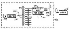
- FIG. 3shows a hub for use in a PON constructed in accordance with the present invention. While for purposes of illustration only the hub will be sometimes referred to as a head end for a PON employed in a CATV network, those of ordinary skill in the art will recognize that the invention could also serve as the hub for any PON in a telephone access system, for example.
- the head end 302 in FIG. 3replaces the high power optical amplifiers 208 with a cladding pumped EDFA that comprises a single, double-cladded doped fiber 308 and one or more pump sources 309 (only one of which is shown in FIG. 3 ), which advantageously may be multimode pump sources.
- a combiner 314is used to couple the pump energy from the pump sources 309 to signal fiber 311 .
- the doped fiber 308which is located at an intermediate point along the signal fiber 311 , amplifies the signal using the pump energy it receives from the pump sources 309 via the combiner 314 .
- An isolator 307is provided between the driver amplifier 304 and the doped fiber 308 to prevent counter-propagating pump energy from reaching the driver amplifier 304 .
- the combiner 314may be built into the backplane of the head end chassis.
- the modules that are inserted into the chassisare simply pump source modules rather than optical amplifier modules.
- pump sources 309may be multimode pumps, which are less expensive than the single mode pump sources required by the hub in FIG. 2 .
- the inventionalso contemplates a similar arrangement in which the doped fiber 308 is co-pumped.
- One disadvantage of the head end 302 shown in FIG. 3arises because all the optical signals are amplified by the cladding pumped EDFA on the signal fiber 311 before the signal reaches the splitters 306 and 310 .
- the power of the optical signals being transmitted to all the customers via splitters 306 and 310is increased.
- an optical amplifier 208is added in FIG. 2 to increase capacity, the power level of the signals being amplified by the previously installed optical amplifiers 208 will be unchanged.
- the customerwill need to make appropriate adjustments to the network such as rearranging splitter loss to accommodate the increase in signal power.
- the PONwill necessarily experience some operational downtime whenever capacity is increased in this manner. This problem is overcome with the embodiment of the invention depicted in FIG. 4 .
- FIGS. 3 and 4pump energy is supplied from the pump sources 309 to doped fiber 308 in the same manner as in FIG. 3 .
- a 1 ⁇ N splitter 316is also provided, which has an input port that receives the amplified optical signals from the doped fiber 308 .
- pump source 309now includes an integrated splitter 313 located in the same module as the pump source 309 , thereby forming a pump/splitter module 315 . That is, in this embodiment of the invention the modules that are inserted into the chassis are pump/splitter modules rather than the pump modules employed in FIG. 3 . In this embodiment of the invention both the combiner 314 and the splitter 316 may be located in the backplane of the head end chassis.
- one of the output ports of the splitter 316 on which a portion of the optical signal is now carriedis coupled to an input of the splitter in the pump/splitter module 315 .
- the pump/splitter modules 315will be coupled to an unused input of the combiner 314 (for supplying pump energy) and to an unused output of the splitter 316 (to receive a portion of the optical signal). In this way the power level of the signals provided by previously installed ones of the pump/splitter module 315 will not be affected when capacity is increased.
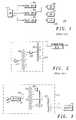
- FIG. 5shows another embodiment of the invention that avoids the need for the splitter 316 used in FIG. 4 while still maintaining the power level of the signals provided by previously installed ones of the pump/splitter module 315 when capacity is increased.
- the amplified optical signals received from doped fiber 308 on signal fiber 311are directed to a pump/splitter module 315 of the type depicted in FIG. 4 .
- Pump/splitter module 315includes pump source 316 and splitter 313 .
- the power level of the amplified optical signals received by each of the pump/splitter modules 315will increase.
- VRCvariable ratio coupler
- the VRC 318has an input that receives the amplified optical signals from signal fiber 311 and two outputs. The first output directs a portion of the amplified optical signals to the splitter 313 and the second output directs the remaining portion of the amplified optical signals to a tap fiber 319 for elimination.
- the VRC 318has a variable coupling ratio, which determines the distribution of power between its two outputs. In this way the signal power provided to the splitter 313 can be maintained at a constant level even as additional pump/splitter modules 315 are added to the head end.
- FIG. 6shows yet another embodiment of the invention that avoids such wastage by reusing excess optical power that arises when additional pump/splitter modules 315 are added.
- FIG. 6is similar to FIG. 5 except that in FIG. 6 two pump/splitter modules 315 1 and 315 2 are shown. Also, in FIG. 6 , the tap fiber 319 of the first pump/splitter module 315 1 is coupled to the input of the VRC 318 of the second pump/splitter module 315 2 . In this way excess optical signal power that is unused by the first pump/splitter module 315 1 can be used by the second pump/splitter module 315 2 . Likewise, if a third pump/splitter module 315 (not shown in FIG.
- excess optical signal power that is not used by the second pump/splitter module 315 2can be used by the third pump/splitter module by coupling the tap fiber 319 of the second pump splitter module 315 2 to the input of the VRC 318 of the third pump/splitter module.
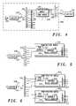
- FIG. 7shows a further enhancement of the present invention that may be employed in connection with either of the embodiments shown in FIGS. 5 and 6 .
- the coupling ratio of the VRCs 318are automatically adjusted when the optical signal power varies as a result of adding (or removing) pump/splitter modules 315 , thereby reducing operational downtime.
- the pump/splitter modules 315include a photodiode 322 that receives, via a tap 320 , a small portion of the optical signal power being directed from the output of the VRC 318 to the input of the splitter 313 .
- the photodiode 322monitors the power level of the optical signal being directed to the splitter 313 and sends an electrical reference signal to a controller 324 .
- the VRC 318is connected to the controller 324 so that control signals sent from the controller to the VRC 318 varies the coupling ratio of the VRC 318 .
- the controller 324is programmed (via software, firmware, hardware, or any combination thereof) to adjust the coupling ratio of the VRC 318 so that the photodiode 320 always detects the same amount of optical power.
- the controller 324 in any given one of the previously installed pump/splitter modules 315will send a control signal to its VRC 318 to adjust the coupling ratio so that the optical power being monitored is reduced, while the optical power being directed by the VRC 318 to the tap fiber is increased.
- This change in the coupling ratiowill result in more excess optical power being directed from the tap fiber 319 of each pump/splitter module 315 to its subsequent pump/splitter module.
- FIGS. 6 and 7One limitation of the embodiments of the invention shown in FIGS. 6 and 7 is that if one of the pump/splitter modules 315 becomes inoperable, all subsequent downstream modules 315 will be adversely impacted because they will not receive the optical signal from the inoperable module 315 .
- This problemis overcome with the embodiment of the invention shown in FIG. 8 in which two 1 ⁇ N optical switches 330 and 340 are employed. While in the particular embodiment of the invention depicted in FIG. 8 N is equal to 8, those ordinary skill in the art will recognize that N may be any integer greater than 2.
- optical switch 330is located in the head end chassis and receives at its input the amplified optical signal from the doped fiber 308 .
- N splitters 350 1 , 350 2 , . . . 350 Nare also provided in the head end chassis. It should be noted that while for simplicity of presentation reference numeral 350 1 is referred to as a splitter, it is actually a single fiber, which for purposes herein may be considered a splitter with a single input and output port.
- Each splitter 350 ihas i output ports.
- splitter 350 4has 4 output ports and splitter 350 8 has 8 output ports.
- the input port of each splitter 350is sequencially coupled to the output ports of the 1 ⁇ N optical switch 330 .
- optical switch 350is switched to its fifth output, for instance, the amplified optical signal is directed to the input of the five-port splitter 350 5 .
- 1 ⁇ N optical switch 340is located in the pump splitter/module 315 .
- Optical switch 340is arranged so that its N input ports are sequentially coupled to an output of the N splitters 350 (i.e., input port j of optical switch 340 is coupled to an output of splitter 350 j ).
- the output of optical switch 340is coupled to the input of the splitter 313 that is integrated with pump/splitter module 315 .
- optical switch 330 located in the head end chassisis switched to its first output position so that the amplified optical signal is directed to splitter (i.e. optical fiber) 350 1 .
- optical switch 340 located in pump/splitter module 315is switched to its first input position so that it received the amplified optical signal form splitter 350 1 and directs it to the splitter 313 .
- Optical switches 330 and 340may be configured annually, or alternatively, they may be configured automatically using microprocessor control.
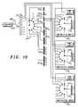
- FIG. 9shows the arrangement of switches 330 and 340 when two pump/splitter modules 315 1 and 315 2 are inserted into the head end.
- optical switch 330is switched to its second output position so that the amplified optical signal is directed to splitter 350 2 .
- optical switch 340 1 in module 315 1 and optical switch 340 2 in module 315 2are both switched to their respective second input positions. In this way the portions of the amplified optical signal that are split between the two outputs of splitter 350 2 are received by pump/splitter modules 315 1 and 315 2 , respectively.
- the optical switches 340 1 and 340 2direct the optical signals to their respective splitters 313 1 and 313 2 .
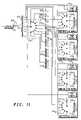
- FIGS. 10-11shows the arrangement of switches 330 and 340 as additional pump/modules 315 are added.
- three pump/splitter modules 315 1 , 315 2 , and 315 3are employed.
- optical switch 330is switched to its third output position and optical switches 340 1 , 340 2 , and 340 3 are switched to their third input position.
- four pump/modules 315are employed and the switches 330 and 340 1 , 340 2 , 340 3 , and 340 4 are all in their fourth position.
- FIGS. 8-11one important advantage of the embodiment of the invention shown in FIGS. 8-11 is that if any given pump/splitter module 315 were to fail, the remaining pump/splitter modules would be unaffected. Another advantage of this embodiment of the invention arises if one of the splitters 350 should fail. For example, referring to FIG. 11 , assume splitter 350 4 fails so that the optical signals cannot be transmitted from splitter 350 4 to the modules 315 1 , 315 2 , 315 3 , and 315 4 . In this case power can be restored to the modules by switching optical switch 330 and optical switches 340 1 , 340 2 , 340 3 and 340 4 to their fifth position.
- FIG. 12shows another embodiment of the invention that overcomes this problem by providing a degree of redundancy.
- a second optical switch 360is located in the head end chassis to which the optical signal can be diverted by a VRC 362 in the event that the optical switch 330 should fail.
- VRC 362has an input that receives the amplified optical signal from doped fiber 308 along signal fiber 311 .
- VRC 362has two outputs that are respectively coupled to the inputs of optical switches 330 and 360 .
- a series of VRCs 380are also provided, which interconnect the outputs of switches 330 and 360 to the splitters 350 , respectively.
- the VRCs 380have two inputs and a single output.
- the outputs of optical switch 330are respectively coupled to one of the inputs of the VRCs 380 .
- the outputs of optical switch 360are respectively coupled to the other input of the VRCs 380 .
- the outputs of the VRCs 380are respectively coupled to the inputs of the splitters 350 .
- the splitters 350are connected to the pump/splitter modules 315 in the previously described manner.
- VRCs 362 and 380instead of VRCs 362 and 380 , other switching elements may be employed, such as a 1 ⁇ 2 switch, for example.
- a 1 ⁇ 2 switchfor example.
- the coupling ratio of VRC 362is adjusted so that all the signal power is directed to optical switch 330 .
- the coupling ratio of VRCs 380are adjusted so that all the signal power arriving from the outputs of switch 330 and received on the first input of the VRCs 380 are directed to the splitters 350 .
- the coupling ratio of VRC 362is adjusted so that all the signal power is directed to optical switch 360 .
- the coupling ratio of VRCs 380are adjusted so that all the signal power arriving from the outputs of switch 360 and received on the second input of the VRCs 380 are directed to the splitters 350 .
Landscapes
- Engineering & Computer Science (AREA)
- Physics & Mathematics (AREA)
- Electromagnetism (AREA)
- Computer Networks & Wireless Communication (AREA)
- Signal Processing (AREA)
- Computing Systems (AREA)
- Optical Communication System (AREA)
- Lasers (AREA)
Abstract
Description
Claims (41)
Priority Applications (1)
| Application Number | Priority Date | Filing Date | Title |
|---|---|---|---|
| US10/638,954US7366416B2 (en) | 2003-08-11 | 2003-08-11 | Hub for a passive optical network hub |
Applications Claiming Priority (1)
| Application Number | Priority Date | Filing Date | Title |
|---|---|---|---|
| US10/638,954US7366416B2 (en) | 2003-08-11 | 2003-08-11 | Hub for a passive optical network hub |
Publications (2)
| Publication Number | Publication Date |
|---|---|
| US20050036786A1 US20050036786A1 (en) | 2005-02-17 |
| US7366416B2true US7366416B2 (en) | 2008-04-29 |
Family
ID=34135777
Family Applications (1)
| Application Number | Title | Priority Date | Filing Date |
|---|---|---|---|
| US10/638,954Expired - LifetimeUS7366416B2 (en) | 2003-08-11 | 2003-08-11 | Hub for a passive optical network hub |
Country Status (1)
| Country | Link |
|---|---|
| US (1) | US7366416B2 (en) |
Cited By (23)
| Publication number | Priority date | Publication date | Assignee | Title |
|---|---|---|---|---|
| US20080267574A1 (en)* | 2005-03-15 | 2008-10-30 | Adc Telecommunications, Inc. | Normal Through Optical Panel |
| US20180287702A1 (en)* | 2017-03-31 | 2018-10-04 | Nexans | Fiber optic extender |
| US10768382B2 (en) | 2018-11-29 | 2020-09-08 | Corning Research & Development Corporation | Multiport assemblies including access apertures and a release tool |
| US10802228B2 (en) | 2017-06-28 | 2020-10-13 | Corning Research & Development Corporation | Fiber optic connectors and multiport assemblies including retention features |
| US10809463B2 (en) | 2017-06-28 | 2020-10-20 | Corning Research & Development Corporation | Multiports and optical connectors with rotationally discrete locking and keying features |
| US11187859B2 (en) | 2017-06-28 | 2021-11-30 | Corning Research & Development Corporation | Fiber optic connectors and methods of making the same |
| US11294133B2 (en) | 2019-07-31 | 2022-04-05 | Corning Research & Development Corporation | Fiber optic networks using multiports and cable assemblies with cable-to-connector orientation |
| US11300746B2 (en) | 2017-06-28 | 2022-04-12 | Corning Research & Development Corporation | Fiber optic port module inserts, assemblies and methods of making the same |
| US11487073B2 (en) | 2019-09-30 | 2022-11-01 | Corning Research & Development Corporation | Cable input devices having an integrated locking feature and assemblies using the cable input devices |
| US11536921B2 (en) | 2020-02-11 | 2022-12-27 | Corning Research & Development Corporation | Fiber optic terminals having one or more loopback assemblies |
| US11604320B2 (en) | 2020-09-30 | 2023-03-14 | Corning Research & Development Corporation | Connector assemblies for telecommunication enclosures |
| US11650388B2 (en) | 2019-11-14 | 2023-05-16 | Corning Research & Development Corporation | Fiber optic networks having a self-supporting optical terminal and methods of installing the optical terminal |
| US11668890B2 (en) | 2017-06-28 | 2023-06-06 | Corning Research & Development Corporation | Multiports and other devices having optical connection ports with securing features and methods of making the same |
| US11686913B2 (en) | 2020-11-30 | 2023-06-27 | Corning Research & Development Corporation | Fiber optic cable assemblies and connector assemblies having a crimp ring and crimp body and methods of fabricating the same |
| US11880076B2 (en) | 2020-11-30 | 2024-01-23 | Corning Research & Development Corporation | Fiber optic adapter assemblies including a conversion housing and a release housing |
| US11886010B2 (en) | 2019-10-07 | 2024-01-30 | Corning Research & Development Corporation | Fiber optic terminals and fiber optic networks having variable ratio couplers |
| US11927810B2 (en) | 2020-11-30 | 2024-03-12 | Corning Research & Development Corporation | Fiber optic adapter assemblies including a conversion housing and a release member |
| US11947167B2 (en) | 2021-05-26 | 2024-04-02 | Corning Research & Development Corporation | Fiber optic terminals and tools and methods for adjusting a split ratio of a fiber optic terminal |
| US11994722B2 (en) | 2020-11-30 | 2024-05-28 | Corning Research & Development Corporation | Fiber optic adapter assemblies including an adapter housing and a locking housing |
| US12019279B2 (en) | 2019-05-31 | 2024-06-25 | Corning Research & Development Corporation | Multiports and other devices having optical connection ports with sliding actuators and methods of making the same |
| US12044894B2 (en) | 2018-12-28 | 2024-07-23 | Corning Research & Development Corporation | Multiport assemblies including mounting features or dust plugs |
| US12271040B2 (en) | 2017-06-28 | 2025-04-08 | Corning Research & Development Corporation | Fiber optic extender ports, assemblies and methods of making the same |
| US12372727B2 (en) | 2020-10-30 | 2025-07-29 | Corning Research & Development Corporation | Female fiber optic connectors having a rocker latch arm and methods of making the same |
Families Citing this family (14)
| Publication number | Priority date | Publication date | Assignee | Title |
|---|---|---|---|---|
| KR100965941B1 (en)* | 2007-10-05 | 2010-06-24 | 한국과학기술원 | Structure of Remote Node for Providing Enhanced Service in Passive Optical Subscriber Network and Passive Optical Subscriber Network |
| US9276673B2 (en) | 2008-04-24 | 2016-03-01 | Commscope Technologies Llc | Methods and systems for testing a fiber optic network |
| US9275415B2 (en)* | 2012-06-01 | 2016-03-01 | Cisco Technology, Inc. | System for latency reduction in high frequency trading networks |
| CN105991191A (en)* | 2015-02-12 | 2016-10-05 | 中兴通讯股份有限公司 | Signal processing method, signal processing device and passive optical fiber hub |
| TWI818020B (en) | 2018-05-15 | 2023-10-11 | 美商萊特美特股份有限公司 | Photonic processing systems and methods |
| TW202032187A (en)* | 2018-06-04 | 2020-09-01 | 美商萊特美特股份有限公司 | Real-number photonic encoding |
| WO2020176393A1 (en) | 2019-02-25 | 2020-09-03 | Lightmatter, Inc. | Path-number-balanced universal photonic network |
| US10803259B2 (en) | 2019-02-26 | 2020-10-13 | Lightmatter, Inc. | Hybrid analog-digital matrix processors |
| CN114514490A (en) | 2019-07-29 | 2022-05-17 | 轻物质公司 | System and method for analog computation using linear optical processors |
| WO2021102349A1 (en) | 2019-11-22 | 2021-05-27 | Lightmatter Inc. | Linear photonic processors and related methods |
| US12038777B2 (en) | 2020-06-29 | 2024-07-16 | Lightmatter, Inc. | Fast prediction processor |
| JP2023536703A (en) | 2020-07-24 | 2023-08-29 | ライトマター インコーポレイテッド | Systems and methods for exploiting photon degrees of freedom in photonic processors |
| US12373687B2 (en) | 2020-11-30 | 2025-07-29 | Lightmatter, Inc. | Machine learning model training using an analog processor |
| WO2023034300A1 (en) | 2021-08-31 | 2023-03-09 | Lightmatter, Inc. | Fiber-coupled laser light source |
Citations (11)
| Publication number | Priority date | Publication date | Assignee | Title |
|---|---|---|---|---|
| US5321707A (en)* | 1992-07-27 | 1994-06-14 | General Instrument Corporation | Remote pumping for active optical devices |
| US5864644A (en) | 1997-07-21 | 1999-01-26 | Lucent Technologies Inc. | Tapered fiber bundles for coupling light into and out of cladding-pumped fiber devices |
| US5907417A (en) | 1994-12-30 | 1999-05-25 | Lucent Technologies Inc. | Passive optical network with diagnostic loop-back |
| US5914799A (en)* | 1995-09-15 | 1999-06-22 | Koninklijke Ptt Nederland N.V. | Optical network |
| US6104733A (en) | 1998-03-11 | 2000-08-15 | Lucent Technologies Inc. | Multi-stage optical fiber amplifier having high conversion efficiency |
| US6181466B1 (en)* | 1997-08-23 | 2001-01-30 | Pirelle Cavi E Sistemi S.P.A. | Unequal couplers for multimode pumping optical amplifiers |
| US6278816B1 (en) | 1997-12-09 | 2001-08-21 | Scientific-Atlanta, Inc. | Noise reduction technique for cladding pumped optical amplifiers |
| US6351582B1 (en) | 1999-04-21 | 2002-02-26 | Nortel Networks Limited | Passive optical network arrangement |
| US6381047B1 (en) | 1998-05-06 | 2002-04-30 | At&T Corp. | Passive optical network using a fabry-perot laser as a multiwavelength source |
| US6434295B1 (en)* | 1999-01-14 | 2002-08-13 | Jds Uniphase Corporation | Side coupled pumping of double clad fiber gain media |
| US20040076371A1 (en)* | 2002-06-03 | 2004-04-22 | Antoine Bellemare | Lossless optical divider/combiner with pump diversion for scalable optical networks |
- 2003
- 2003-08-11USUS10/638,954patent/US7366416B2/ennot_activeExpired - Lifetime
Patent Citations (11)
| Publication number | Priority date | Publication date | Assignee | Title |
|---|---|---|---|---|
| US5321707A (en)* | 1992-07-27 | 1994-06-14 | General Instrument Corporation | Remote pumping for active optical devices |
| US5907417A (en) | 1994-12-30 | 1999-05-25 | Lucent Technologies Inc. | Passive optical network with diagnostic loop-back |
| US5914799A (en)* | 1995-09-15 | 1999-06-22 | Koninklijke Ptt Nederland N.V. | Optical network |
| US5864644A (en) | 1997-07-21 | 1999-01-26 | Lucent Technologies Inc. | Tapered fiber bundles for coupling light into and out of cladding-pumped fiber devices |
| US6181466B1 (en)* | 1997-08-23 | 2001-01-30 | Pirelle Cavi E Sistemi S.P.A. | Unequal couplers for multimode pumping optical amplifiers |
| US6278816B1 (en) | 1997-12-09 | 2001-08-21 | Scientific-Atlanta, Inc. | Noise reduction technique for cladding pumped optical amplifiers |
| US6104733A (en) | 1998-03-11 | 2000-08-15 | Lucent Technologies Inc. | Multi-stage optical fiber amplifier having high conversion efficiency |
| US6381047B1 (en) | 1998-05-06 | 2002-04-30 | At&T Corp. | Passive optical network using a fabry-perot laser as a multiwavelength source |
| US6434295B1 (en)* | 1999-01-14 | 2002-08-13 | Jds Uniphase Corporation | Side coupled pumping of double clad fiber gain media |
| US6351582B1 (en) | 1999-04-21 | 2002-02-26 | Nortel Networks Limited | Passive optical network arrangement |
| US20040076371A1 (en)* | 2002-06-03 | 2004-04-22 | Antoine Bellemare | Lossless optical divider/combiner with pump diversion for scalable optical networks |
Cited By (64)
| Publication number | Priority date | Publication date | Assignee | Title |
|---|---|---|---|---|
| US7587116B2 (en)* | 2005-03-15 | 2009-09-08 | Adc Telecommunications, Inc. | Normal through optical panel |
| US20080267574A1 (en)* | 2005-03-15 | 2008-10-30 | Adc Telecommunications, Inc. | Normal Through Optical Panel |
| US10797797B2 (en)* | 2017-03-31 | 2020-10-06 | Nexans | Fiber optic extender |
| US20180287702A1 (en)* | 2017-03-31 | 2018-10-04 | Nexans | Fiber optic extender |
| US11668890B2 (en) | 2017-06-28 | 2023-06-06 | Corning Research & Development Corporation | Multiports and other devices having optical connection ports with securing features and methods of making the same |
| US11215768B2 (en) | 2017-06-28 | 2022-01-04 | Corning Research & Development Corporation | Fiber optic connectors and connectorization employing adhesive admitting adapters |
| US10809463B2 (en) | 2017-06-28 | 2020-10-20 | Corning Research & Development Corporation | Multiports and optical connectors with rotationally discrete locking and keying features |
| US11187859B2 (en) | 2017-06-28 | 2021-11-30 | Corning Research & Development Corporation | Fiber optic connectors and methods of making the same |
| US12429655B2 (en) | 2017-06-28 | 2025-09-30 | Corning Optical Communications LLC | Multiports having connection ports with associated securing features and methods of making the same |
| US11262509B2 (en) | 2017-06-28 | 2022-03-01 | Corning Research & Development Corporation | Compact fiber optic connectors having multiple connector footprints, along with cable assemblies and methods of making the same |
| US11287581B2 (en) | 2017-06-28 | 2022-03-29 | Corning Research & Development Corporation | Compact fiber optic connectors, cable assemblies and methods of making the same |
| US11287582B2 (en) | 2017-06-28 | 2022-03-29 | Corning Research & Development Corporation | Compact fiber optic connectors, cable assemblies and methods of making the same |
| US12379551B2 (en) | 2017-06-28 | 2025-08-05 | Corning Optical Communications LLC | Multiports having connection ports formed in the shell and associated securing features |
| US11300735B2 (en) | 2017-06-28 | 2022-04-12 | Corning Research & Development Corporation | Compact fiber optic connectors having multiple connector footprints, along with cable assemblies and methods of making the same |
| US11300746B2 (en) | 2017-06-28 | 2022-04-12 | Corning Research & Development Corporation | Fiber optic port module inserts, assemblies and methods of making the same |
| US11307364B2 (en) | 2017-06-28 | 2022-04-19 | Corning Research & Development Corporation | Compact fiber optic connectors having multiple connector footprints, along with cable assemblies and methods of making the same |
| US11327247B2 (en) | 2017-06-28 | 2022-05-10 | Corning Optical Communications LLC | Multiports having connection ports formed in the shell and associated securing features |
| US11409055B2 (en) | 2017-06-28 | 2022-08-09 | Corning Optical Communications LLC | Multiports having connection ports with associated securing features and methods of making the same |
| US11415759B2 (en) | 2017-06-28 | 2022-08-16 | Corning Optical Communications LLC | Multiports having a connection port insert and methods of making the same |
| US11460646B2 (en) | 2017-06-28 | 2022-10-04 | Corning Research & Development Corporation | Fiber optic connectors and multiport assemblies including retention features |
| US12379552B2 (en) | 2017-06-28 | 2025-08-05 | Corning Research & Development Corporation | Compact fiber optic connectors, cable assemblies and methods of making the same |
| US11487065B2 (en) | 2017-06-28 | 2022-11-01 | Corning Research & Development Corporation | Multiports and devices having a connector port with a rotating securing feature |
| US11493700B2 (en) | 2017-06-28 | 2022-11-08 | Corning Research & Development Corporation | Compact fiber optic connectors, cable assemblies and methods of making the same |
| US11493699B2 (en) | 2017-06-28 | 2022-11-08 | Corning Research & Development Corporation | Multifiber fiber optic connectors, cable assemblies and methods of making the same |
| US11531168B2 (en) | 2017-06-28 | 2022-12-20 | Corning Research & Development Corporation | Fiber optic connectors having a keying structure and methods of making the same |
| US11536913B2 (en) | 2017-06-28 | 2022-12-27 | Corning Research & Development Corporation | Fiber optic connectors and connectorization employing adhesive admitting adapters |
| US12353025B2 (en) | 2017-06-28 | 2025-07-08 | Corning Optical Communications LLC | Multiports having a connection port insert and methods of making the same |
| US11543600B2 (en) | 2017-06-28 | 2023-01-03 | Corning Research & Development Corporation | Compact fiber optic connectors having multiple connector footprints, along with cable assemblies and methods of making the same |
| US11579377B2 (en) | 2017-06-28 | 2023-02-14 | Corning Research & Development Corporation | Compact fiber optic connectors, cable assemblies and methods of making the same with alignment elements |
| US12353024B2 (en) | 2017-06-28 | 2025-07-08 | Corning Research & Development Corporation | Multiports and optical connectors with rotationally discrete locking and keying features |
| US11624877B2 (en) | 2017-06-28 | 2023-04-11 | Corning Research & Development Corporation | Multiports having connection ports with securing features that actuate flexures and methods of making the same |
| US12298568B2 (en) | 2017-06-28 | 2025-05-13 | Corning Research & Development Corporation | Fiber optic connectors and multiport assemblies including retention features |
| US10802228B2 (en) | 2017-06-28 | 2020-10-13 | Corning Research & Development Corporation | Fiber optic connectors and multiport assemblies including retention features |
| US12276846B2 (en) | 2017-06-28 | 2025-04-15 | Corning Research & Development Corporation | Compact fiber optic connectors, cable assemblies and methods of making the same |
| US11656414B2 (en) | 2017-06-28 | 2023-05-23 | Corning Research & Development Corporation | Multiports and other devices having connection ports with securing features and methods of making the same |
| US11703646B2 (en) | 2017-06-28 | 2023-07-18 | Corning Research & Development Corporation | Multiports and optical connectors with rotationally discrete locking and keying features |
| US11789214B2 (en) | 2017-06-28 | 2023-10-17 | Corning Research & Development Corporation | Multiports and other devices having keyed connection ports and securing features and methods of making the same |
| US12271040B2 (en) | 2017-06-28 | 2025-04-08 | Corning Research & Development Corporation | Fiber optic extender ports, assemblies and methods of making the same |
| US11886017B2 (en) | 2017-06-28 | 2024-01-30 | Corning Research & Development Corporation | Multiports and other devices having connection ports with securing features and methods of making the same |
| US12174432B2 (en) | 2017-06-28 | 2024-12-24 | Corning Research & Development Corporation | Fiber optic connectors and connectorization employing adhesive admitting adapters |
| US11906792B2 (en) | 2017-06-28 | 2024-02-20 | Corning Research & Development Corporation | Compact fiber optic connectors having multiple connector footprints, along with cable assemblies and methods of making the same |
| US11914197B2 (en) | 2017-06-28 | 2024-02-27 | Corning Research & Development Corporation | Compact fiber optic connectors having multiple connector footprints, along with cable assemblies and methods of making the same |
| US11914198B2 (en) | 2017-06-28 | 2024-02-27 | Corning Research & Development Corporation | Compact fiber optic connectors having multiple connector footprints, along with cable assemblies and methods of making the same |
| US12092878B2 (en) | 2017-06-28 | 2024-09-17 | Corning Research & Development Corporation | Fiber optic connectors having a keying structure and methods of making the same |
| US11940656B2 (en) | 2017-06-28 | 2024-03-26 | Corning Research & Development Corporation | Compact fiber optic connectors, cable assemblies and methods of making the same |
| US12013578B2 (en) | 2017-06-28 | 2024-06-18 | Corning Research & Development Corporation | Multifiber fiber optic connectors, cable assemblies and methods of making the same |
| US11966089B2 (en) | 2017-06-28 | 2024-04-23 | Corning Optical Communications, Llc | Multiports having connection ports formed in the shell and associated securing features |
| US10768382B2 (en) | 2018-11-29 | 2020-09-08 | Corning Research & Development Corporation | Multiport assemblies including access apertures and a release tool |
| US12044894B2 (en) | 2018-12-28 | 2024-07-23 | Corning Research & Development Corporation | Multiport assemblies including mounting features or dust plugs |
| US12019279B2 (en) | 2019-05-31 | 2024-06-25 | Corning Research & Development Corporation | Multiports and other devices having optical connection ports with sliding actuators and methods of making the same |
| US11294133B2 (en) | 2019-07-31 | 2022-04-05 | Corning Research & Development Corporation | Fiber optic networks using multiports and cable assemblies with cable-to-connector orientation |
| US11487073B2 (en) | 2019-09-30 | 2022-11-01 | Corning Research & Development Corporation | Cable input devices having an integrated locking feature and assemblies using the cable input devices |
| US11886010B2 (en) | 2019-10-07 | 2024-01-30 | Corning Research & Development Corporation | Fiber optic terminals and fiber optic networks having variable ratio couplers |
| US11650388B2 (en) | 2019-11-14 | 2023-05-16 | Corning Research & Development Corporation | Fiber optic networks having a self-supporting optical terminal and methods of installing the optical terminal |
| US11536921B2 (en) | 2020-02-11 | 2022-12-27 | Corning Research & Development Corporation | Fiber optic terminals having one or more loopback assemblies |
| US11604320B2 (en) | 2020-09-30 | 2023-03-14 | Corning Research & Development Corporation | Connector assemblies for telecommunication enclosures |
| US12019285B2 (en) | 2020-09-30 | 2024-06-25 | Corning Research & Development Corporation | Connector assemblies for telecommunication enclosures |
| US12372727B2 (en) | 2020-10-30 | 2025-07-29 | Corning Research & Development Corporation | Female fiber optic connectors having a rocker latch arm and methods of making the same |
| US11994722B2 (en) | 2020-11-30 | 2024-05-28 | Corning Research & Development Corporation | Fiber optic adapter assemblies including an adapter housing and a locking housing |
| US11880076B2 (en) | 2020-11-30 | 2024-01-23 | Corning Research & Development Corporation | Fiber optic adapter assemblies including a conversion housing and a release housing |
| US11927810B2 (en) | 2020-11-30 | 2024-03-12 | Corning Research & Development Corporation | Fiber optic adapter assemblies including a conversion housing and a release member |
| US12345927B2 (en) | 2020-11-30 | 2025-07-01 | Corning Research & Development Corporation | Fiber optic adapter assemblies including a conversion housing and a release housing |
| US11686913B2 (en) | 2020-11-30 | 2023-06-27 | Corning Research & Development Corporation | Fiber optic cable assemblies and connector assemblies having a crimp ring and crimp body and methods of fabricating the same |
| US11947167B2 (en) | 2021-05-26 | 2024-04-02 | Corning Research & Development Corporation | Fiber optic terminals and tools and methods for adjusting a split ratio of a fiber optic terminal |
Also Published As
| Publication number | Publication date |
|---|---|
| US20050036786A1 (en) | 2005-02-17 |
Similar Documents
| Publication | Publication Date | Title |
|---|---|---|
| US7366416B2 (en) | Hub for a passive optical network hub | |
| US5241414A (en) | Fault tolerant optical amplifier arrangement | |
| US7133193B2 (en) | Optical transmission systems including optical amplifiers, apparatuses and methods | |
| EP0532230B1 (en) | Optical amplifiers having pump redundancy | |
| US7787764B2 (en) | Optical network transmission channel failover switching device | |
| EP2727271B1 (en) | Optical communication system, device and method for data processing in an optical network | |
| CA2363152C (en) | Wdm transmitter | |
| US6809858B2 (en) | Optical transmission systems and optical amplifiers for use therein | |
| US8055132B2 (en) | Optical remote node device and support equipment for constructing and extending fiber-optic access networks | |
| EP1535411B1 (en) | Method and apparatus for sharing pump energy from a single pump arrangement to optical fibers located in different fiber pairs | |
| US9509430B2 (en) | Apparatus for optical signal amplification | |
| US7020168B2 (en) | High power multi-frequency laser | |
| US20080166122A1 (en) | Optical network backup channel switching control device | |
| CA2535393A1 (en) | Asymmetric distribution of optical pump power | |
| AU752286B2 (en) | Improvement in the reliability of an optical communication system and of an optical amplifying system, and a method suitable to this aim | |
| US20020167719A1 (en) | Method of pump wavelength combing for enhanced power dynamic range and redundancy broad band raman optical amplifier system | |
| US7119948B2 (en) | Optical amplifier apparatus and method | |
| US7088498B2 (en) | Optical amplification of CWDM channels using optical amplifiers having fluoride-based optical fiber | |
| EP0878927B1 (en) | Improvement in the reliability of an optical communication system and a method suitable to this aim | |
| Mestdagh et al. | The Super-PON concept and its technical | |
| WO1998052305A1 (en) | Redundant optical power supply for remote pumping of fiber optic gain modules |
Legal Events
| Date | Code | Title | Description |
|---|---|---|---|
| AS | Assignment | Owner name:GENERAL INSTRUMENT CORPORATION, PENNSYLVANIA Free format text:ASSIGNMENT OF ASSIGNORS INTEREST;ASSIGNORS:RAMACHANDRAN, MANI;JASTI, CHANDRA SEKHAR;REEL/FRAME:014897/0476 Effective date:20030923 | |
| STCF | Information on status: patent grant | Free format text:PATENTED CASE | |
| CC | Certificate of correction | ||
| FPAY | Fee payment | Year of fee payment:4 | |
| AS | Assignment | Owner name:MOTOROLA MOBILITY LLC, ILLINOIS Free format text:ASSIGNMENT OF ASSIGNORS INTEREST;ASSIGNOR:GENERAL INSTRUMENT HOLDINGS, INC.;REEL/FRAME:030866/0113 Effective date:20130528 Owner name:GENERAL INSTRUMENT HOLDINGS, INC., CALIFORNIA Free format text:ASSIGNMENT OF ASSIGNORS INTEREST;ASSIGNOR:GENERAL INSTRUMENT CORPORATION;REEL/FRAME:030764/0575 Effective date:20130415 | |
| AS | Assignment | Owner name:GOOGLE TECHNOLOGY HOLDINGS LLC, CALIFORNIA Free format text:ASSIGNMENT OF ASSIGNORS INTEREST;ASSIGNOR:MOTOROLA MOBILITY LLC;REEL/FRAME:034472/0001 Effective date:20141028 | |
| FPAY | Fee payment | Year of fee payment:8 | |
| MAFP | Maintenance fee payment | Free format text:PAYMENT OF MAINTENANCE FEE, 12TH YEAR, LARGE ENTITY (ORIGINAL EVENT CODE: M1553); ENTITY STATUS OF PATENT OWNER: LARGE ENTITY Year of fee payment:12 |