US7366391B2 - Hybrid wire-fiber management - Google Patents
Hybrid wire-fiber managementDownload PDFInfo
- Publication number
- US7366391B2 US7366391B2US11/419,968US41996806AUS7366391B2US 7366391 B2US7366391 B2US 7366391B2US 41996806 AUS41996806 AUS 41996806AUS 7366391 B2US7366391 B2US 7366391B2
- Authority
- US
- United States
- Prior art keywords
- movable
- rack
- cabinet
- stationary
- trays
- Prior art date
- Legal status (The legal status is an assumption and is not a legal conclusion. Google has not performed a legal analysis and makes no representation as to the accuracy of the status listed.)
- Expired - Fee Related
Links
- 239000000835fiberSubstances0.000titleclaimsdescription33
- 239000013307optical fiberSubstances0.000claimsabstractdescription53
- 238000004891communicationMethods0.000description12
- 238000000034methodMethods0.000description11
- RYGMFSIKBFXOCR-UHFFFAOYSA-NCopperChemical compound[Cu]RYGMFSIKBFXOCR-UHFFFAOYSA-N0.000description4
- 229910052802copperInorganic materials0.000description3
- 239000010949copperSubstances0.000description3
- 239000000463materialSubstances0.000description3
- 238000009434installationMethods0.000description2
- 230000008569processEffects0.000description2
- 230000032683agingEffects0.000description1
- 238000005452bendingMethods0.000description1
- 230000008901benefitEffects0.000description1
- 230000015556catabolic processEffects0.000description1
- 239000002131composite materialSubstances0.000description1
- 238000006731degradation reactionMethods0.000description1
- 230000009977dual effectEffects0.000description1
- 230000006870functionEffects0.000description1
- 238000004519manufacturing processMethods0.000description1
- 229910052751metalInorganic materials0.000description1
- 239000002184metalSubstances0.000description1
- 150000002739metalsChemical class0.000description1
- 230000005012migrationEffects0.000description1
- 238000013508migrationMethods0.000description1
- 201000002266mite infestationDiseases0.000description1
- 238000012986modificationMethods0.000description1
- 230000004048modificationEffects0.000description1
- 239000004033plasticSubstances0.000description1
- 229920003023plasticPolymers0.000description1
- 229920000642polymerPolymers0.000description1
- 239000003566sealing materialSubstances0.000description1
- 230000008054signal transmissionEffects0.000description1
Images


Classifications
- G—PHYSICS
- G02—OPTICS
- G02B—OPTICAL ELEMENTS, SYSTEMS OR APPARATUS
- G02B6/00—Light guides; Structural details of arrangements comprising light guides and other optical elements, e.g. couplings
- G02B6/44—Mechanical structures for providing tensile strength and external protection for fibres, e.g. optical transmission cables
- G02B6/4439—Auxiliary devices
- G02B6/444—Systems or boxes with surplus lengths
- G02B6/44528—Patch-cords; Connector arrangements in the system or in the box
- G—PHYSICS
- G02—OPTICS
- G02B—OPTICAL ELEMENTS, SYSTEMS OR APPARATUS
- G02B6/00—Light guides; Structural details of arrangements comprising light guides and other optical elements, e.g. couplings
- G02B6/44—Mechanical structures for providing tensile strength and external protection for fibres, e.g. optical transmission cables
- G02B6/4439—Auxiliary devices
- G02B6/444—Systems or boxes with surplus lengths
- G02B6/4452—Distribution frames
- G02B6/44524—Distribution frames with frame parts or auxiliary devices mounted on the frame and collectively not covering a whole width of the frame or rack
Definitions
- the following disclosurerelates generally to systems for managing and organizing signal-transmission lines, such as wires and optical fibers. More specifically, the disclosure relates to hybrid systems for managing and organizing signal-carrying wires and optical fibers.
- Copper wireshave long been used in the telecommunications industry to transmit information within and between individual telecommunications facilities. More recently, telecommunications facilities have begun to replace the aging copper wires with optical fibers. Optical fibers are able to transmit large volumes of data and voice signals over relatively long distances, with little or no signal degradation. For this reason, optical fibers have become widely used in the telecommunication field. However, the cost of replacing the existing copper based telecommunications infrastructure is substantial. Accordingly, telecommunications providers typically upgrade their infrastructures in sections, migrating from copper wire to optical fiber gradually.
- the systems used to manage and organize optical fibersare often different than those used to manage wires, since, for example, optical fibers tend to be more susceptible to damage from bending than wires.
- optical fiberstend to be more susceptible to damage from bending than wires.
- a telecommunications companyreplaces a section of wires with optical fibers, they must also replace the systems used to manage that section of wires.
- the section of wires replacedmay be only a portion of the wires managed by a particular wire management system. In that case, it would be necessary to add an additional cabinet, rack, or other management system to handle the new fibers that replace the old section of wires.
- floor spaceis often at a premium in a telecommunications facility, it is desirable to minimize the number of separate cabinets, racks, and/or other management systems.
- Hybrid systems for managing both wires and optical fibersare disclosed.
- Exemplary systemsinclude a first rack having trays for managing optical fibers.
- a second rackis disposed proximate to the first rack, and modules are mounted to the second rack for managing wires.
- At least one of the racksis movable at least partially away from the other rack to provide access to both sides of each of the first and second racks.
- a single hybrid systemis configured to mange both wires and optical fibers, thus eliminating the need to use separate racks to manage wires and optical fibers, respectively. Additionally, as more wires are replaced by optical fibers, the hybrid system can be reconfigured over time to hold more and more new optical fibers in place of the old wires. Using such a hybrid system, telecommunications companies can easily migrate gradually from a wire-based system to an optical fiber-based system, without the need for additional racks or cabinets taking up precious floor space.
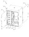
- FIG. 1is a front perspective view of one exemplary hybrid cabinet for managing wires and optical fibers.
- FIG. 2is a rear perspective view of the hybrid cabinet of FIG. 1 .
- FIG. 3is a front view of the hybrid cabinet of FIG. 1 .
- FIG. 5is a side view of the hybrid cabinet of FIG. 1 .
- FIG. 6is a front view of another exemplary hybrid cabinet for managing wires and optical fibers.
- FIG. 7is a rear view of the hybrid cabinet of FIG. 6 .
- FIG. 8is a plan view of the hybrid cabinet of FIG. 6 .
- FIG. 9is a front view of another exemplary hybrid cabinet for managing wires and optical fibers.
- FIG. 10is a plan view of the hybrid cabinet of FIG. 9 .
- FIG. 11is a flow chart showing an exemplary method of migrating from a signal-carrying wire-based communications infrastructure to an optical fiber-based communications infrastructure.
- Hybrid cabinetsare described, which are capable of managing both wires and optical fibers. Such cabinets may, for example, facilitate the replacement of wires of an existing wire-based communication infrastructure with optical fibers. In some implementations, the cabinets allow for replacement of only a portion of the wires managed by a particular wire management system, without the need to add an additional cabinet, rack, or other management system to handle the new fibers that replace the old section of wires.
- the implementationsare described in the context of hybrid cabinets for managing wires and optical fibers in a telecommunications infrastructure. However, the implementations described herein may be used in other environments and are applicable to other contexts. For example, the cabinets may also be used to manage wires and optical fibers in local area communications infrastructures.
- FIGS. 1-5illustrate a hybrid cabinet 100 according to one exemplary implementation.
- FIG. 1is a front perspective view of the hybrid cabinet 100 , and shows a housing 102 of the cabinet 100 comprising an enclosure, including a top surface 104 , a bottom surface (not shown), two side surfaces 106 , a front access door 108 , and a rear access door 110 .
- the terms “front,” “rear,” “top,” “bottom,” “right,” and “left”refer the position or orientation of the cabinet as it is shown in FIG. 1 . However, it should be understood that this convention is arbitrary and that the terms merely describe the position or orientation of one feature relative to another.
- the housing 102substantially encloses contents of the cabinet 100 .
- the front access door 108covers a front opening 112 and the rear access door 10 covers a rear opening 114 .
- Weather stripping or other sealing materialextends substantially around the front and rear openings 112 and 114 so that when the access doors 108 and 110 are closed, the cabinet provides a substantially weather-tight enclosure that protects the contents of the cabinet 100 from the weather.
- the cabinet 100 of FIG. 1is suitable for use as an outdoor cabinet. In other implementations, however, cabinets may include housings that are only partially enclosed or are substantially open, or the housing may be omitted entirely.
- the stationary rack 116is configured to manage wires and has front and back faces.
- the movable rack 118is configured to manage optical fibers, and also has front and back faces.
- the movable rack 118is movable relative to the stationary rack 116 to provide access to both the front and back faces of both the stationary and movable racks 116 and 118 .
- the stationary rack 116could be configured to manage optical fibers, while the movable rack 118 could be configured to manage wires.
- one or both of the stationary and movable racks 116 and 118could be configured to manage both wires and optical fibers.
- both rackscould be movable.
- Slack storage bosses 120are disposed in the cabinet 100 adjacent to the stationary rack 116 for storing and/or routing slack optical fibers and/or wires. While not shown, slack storage bosses could additionally or alternatively be disposed adjacent to the movable rack 118 , or could be mounted on one or both of the stationary and movable racks 116 and 118 . Also, numerous variations in shape, orientation, and/or arrangement of the slack storage bosses could be made and would be apparent to one of ordinary skill in the art.
- FIG. 2is a rear perspective view of the cabinet 100 , showing the movable rack 118 swung partially away from the stationary rack 116 .
- the movable rack 118is movable between a first position (shown in FIGS. 1 and 4 ) providing access to only one face of each of the stationary and movable racks, and a second position (the movable rack 118 is shown partially toward the second position in FIG. 2 ) providing access to both the front and back faces of both the stationary and movable racks 116 and 118 .
- the movable rack 118In the first position the movable rack 118 is proximately adjacent to the stationary rack such that adjacent faces of the stationary and movable racks are inaccessible.
- faces of the stationary and movable racksare spaced apart such that both front and back faces of each of the stationary and movable racks are accessible.
- the movable rack 118is pivotably movable relative to the stationary rack 116 and the rest of the cabinet 100 , such that the movable rack 118 can be swung out to provide access to both faces of the movable rack.
- the movable rackcould be configured to be slidably movable relative to the cabinet and the stationary rack, such that the movable rack could be slid out to provide access to both faces of the movable rack.
- both racksinstead of one rack being stationary, both racks could be pivotable, both racks could be slidable, or one rack could be pivotable while the other is slidable.
- one or more additional stationary, pivotable, and/or slidable rackscould be disposed in the cabinet in any desired configuration.
- FIG. 3is a front view of the hybrid cabinet 100 , schematically showing a plurality of movable trays 300 coupled to the stationary rack 116 for managing optical fibers F.
- the movable trays 300 and fibers Fare shown here, but have been omitted from the other figures for clarity.
- the trays 300may include one or more fiber management structures for storing the fibers or connecting the fibers to one or more other fibers and/or fiber optic devices, such as attenuators, connectors, switches, multiplexers, splitters/combiners, or splices.
- the movable trays 300are movable relative to the stationary rack 116 to provide access to the contents of the individual trays.
- the movable trays 300may be pivotable relative to the stationary rack to provide access to the fiber management structure contained in the tray (as described in more detail below with respect to FIGS. 8 and 10 ). In that case, each tray may be pivotable about one or multiple axes. Alternatively, the trays 300 may be slidable relative to the stationary rack 116 to provide access to the fiber management structure contained in the tray.
- FIG. 4is a rear view of the hybrid cabinet 100 , showing a plurality of modules 400 coupled to the movable rack 118 for managing the wires W.
- the modules 400 and wires Ware shown here, but have been omitted from the other figures for clarity.
- the modules 400may include wire management structures, such as digital cross-connect modules, splitters, combiners, patch connections, and the like.
- the modules 400are shown in this figure as being fixed against movement relative to the movable rack 118 .
- the modulescould be pivotable and/or slidable (movable) relative to the movable rack 118 .
- the modulescould be movably mounted to a stationary rack.
- each tray 300comprises a plurality of fiber optic cross connects
- each module 400comprises a plurality of wire cross connects.
- FIG. 5is a side view of the hybrid cabinet 100 , showing the front and rear access doors 108 and 110 in closed positions, in which the cabinet is substantially weather tight.
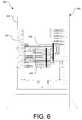
- FIGS. 6-8illustrate another exemplary hybrid cabinet 600 .
- the cabinet 600is similar to the hybrid cabinet of FIGS. 1-5 . Therefore, only features of the cabinet 600 that differ will be described below.
- the cabinet 600is at least partially open, having a generally open framework housing 602 allowing greater access and visibility to the contents of the cabinet 600 .
- the cabinet 600 of this implementationcould be modified to provide a substantially weather-tight enclosure.
- FIG. 6is a front view of the cabinet 600 and shows a first rack 604 in the cabinet 600 having a plurality of trays 606 for managing optical fibers.
- the trays 606 in this implementationare arranged vertically in a single stack of trays and are movable between a storage position within the cabinet and an extended position, in which they protrude from the cabinet to provide access to fiber connectors or other fiber management structure in the trays.
- the top three trays 606are shown in a retracted position within the cabinet 600 , while the remaining trays are shown swung partially outward toward the extended position to provide access to the trays.
- Fiber routing guides 608are disposed along one side of the first rack to guide fibers to and from the trays 606 .
- FIG. 7is a rear view of the cabinet 600 and shows a second rack 700 in the cabinet proximate to the first rack 604 .
- a plurality of modules 702is mounted to the second rack 700 for managing wires.
- the trays 606 and modules 702 of this implementationare the same and may contain the same components as those described above with respect to FIGS. 1-5 .
- At least one, and possibly both, of the first and second racks 604 and 700is movable at least partially out of the cabinet 600 and away from the other of the first and second racks, to provide access to both sides of each of the first and second racks 604 and 700 .
- the first rack 604In the first position the first rack 604 is proximately adjacent to the second rack 700 , such that adjacent faces of the first and second racks are inaccessible.
- faces of the first and second racksare spaced apart such that both front and back faces of each of the first and second racks are accessible.
- the movable rack(s)may be pivotable and/or slidable relative to the cabinet and/or one another. The pivoting and/or sliding motion of the movable one(s) of the rack(s) 604 and 700 is the same as that for the movable rack of FIGS. 1-5 , so the description of that motion will be omitted here.
- the trays 606are movable relative to the first rack 604 , and the modules 702 are fixed against movement relative to the second rack 700 .
- trays 606 and/or modules 702may be fixed to one or both of the first and second racks, they may be movably mounted (e.g., slidably or pivotably) to one or both of the first and second racks.
- one or more additional stationary or fixed racksmay be provided in the cabinet and may have trays and/or modules mounted to them in the foregoing manners as well.
- FIG. 8is a plan view of the cabinet 600 , showing the manner in which trays 606 are pivotable between a storage position within the cabinet and an extended position, in which they protrude from the cabinet to provide access to fiber connectors or other fiber management structure in the trays.
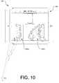
- FIGS. 9 and 10illustrate another exemplary hybrid cabinet 900 .
- the cabinet 900is similar to the hybrid cabinet of FIGS. 1-5 . Therefore, only features of the cabinet 900 that differ will be described below.
- the cabinet 900has a housing 902 that substantially encloses contents of the cabinet 900 and provides a substantially weather-tight enclosure, similar to that of the cabinet of FIGS. 1-5 .
- FIG. 9is a front view of the cabinet 900 and shows a first rack 904 in the cabinet 900 having a plurality of trays 906 for managing optical fibers.
- the first rack 904may be stationary, pivotable, or slidable, in which case it will function in substantially the same manner as the racks described in the foregoing implementations. Accordingly, further description of the first rack 904 will be omitted here.
- the trays 906 in this implementationare arranged in two vertical stacks of trays, a first stack 906 a of trays stacked vertically along one edge of the first rack 904 , and second stack 906 b of trays stacked vertically along an opposed edge of the first rack 904 .
- Each trayis movable between a storage position adjacent one side of the cabinet 900 and an access position in the interior of the cabinet to provide access to fiber connectors or other fiber management structure in the trays.
- the trays in the left-hand stack 906 a and the top six trays in the right-hand stack 906 bare shown in the storage position, while the bottom six trays on the right-hand stack 906 b are shown in the access position providing access to the contents of the trays.
- Slack storage bosses 908are disposed in a central region of the first rack 904 for storing slack or excess optical fibers and/or wires.
- the slack storage bosses 908are arranged in a generally W-shape.
- Slack fibers Fcan be wrapped around the slack storage bosses 908 as shown in dashed lines in FIG. 9 , or in any other desired configuration.
- numerous variations in shape, orientation, and/or arrangement of the slack storage bossescan be made and would be apparent to one of ordinary skill in the art.
- slack storage bossescould additionally or alternatively be disposed adjacent to or on one or more racks of the cabinet 900 .
- a rear view of the cabinet 900would be substantially identical to that shown in FIG. 7 , except for the provision of a rear access door (not shown).
- the rear viewwould show a second rack with modules mounted thereto for managing wires. Accordingly, the rear view of the cabinet 900 and accompanying description have been omitted for brevity.
- trays and/or modulescould be fixed to one or both of the first and second racks, and they could be movably mounted (e.g., slidably or pivotably) to one or both of the first and second racks.
- one or more additional stationary or fixed rackscould be provided in the cabinet and could have trays and/or modules mounted to them in the foregoing manners as well.
- FIG. 10is a plan view of the cabinet 900 of FIG. 9 , with the top panel of the housing 902 removed for clarity. As shown in this view, all of the trays in the left-hand stack 906 a are in the storage position adjacent the left side of the cabinet 900 . Some of the trays in the right-hand stack 906 b are in the storage position, while others are rotated toward the access position in the interior of the cabinet to provide access to fiber connectors or other fiber management structure in the trays.
- each of the cabinetsmay be rearranged, omitted, modified, and/or combined with one another.
- either the single stack of outward-rotating trays shown in FIG. 6 or the dual stack of inward-rotating trays shown in FIG. 9could be adapted for use in the cabinet of FIGS. 1-5 .
- the W-shaped slack storage shown in FIG. 9could be used in place of the slack storage bosses of the cabinet of FIGS. 1-5 , and vice versa.
- both rackscould be stationary, both racks could be movable, additional movable and/or stationary racks could be added, and/or the trays and modules could be mounted to any one or more of the racks. Numerous other variations will be apparent to those of ordinary skill in the art.
- the components of the cabinetscan be made of any material having the desired combination of strength, cost, weight, electrical conductivity, and other material properties, and can be made by conventional manufacturing and assembling processes.
- suitable materialsinclude, for example, metals, plastics, polymers, composites, and the like.
- FIG. 11is a flow chart showing an exemplary method 1100 of migrating from a signal-carrying wire-based communications infrastructure to an optical fiber-based communications infrastructure.
- the method 1100may be implemented using hybrid cabinets such as the foregoing exemplary implementations, or combinations, modifications, or variations thereof.
- the method 1100comprises providing a hybrid cabinet, which in one implementation comprises first structure to manage signal-carrying wires, second structure to manage optical fibers, signal-carrying wire cross connects, and optical fiber cross connects.
- a hybrid cabinetwhich in one implementation comprises first structure to manage signal-carrying wires, second structure to manage optical fibers, signal-carrying wire cross connects, and optical fiber cross connects.
- the methodmay be implemented using other hybrid cabinets, such as those described herein.
- the exemplary methodfurther comprises installing a hybrid cabinet having first structure for managing signal-carrying wires and second structure for managing optical fibers, into an existing communications infrastructure.
- a hybrid cabinethaving first structure for managing signal-carrying wires and second structure for managing optical fibers.
- the section of wires replacedmay be only a portion of the wires managed by a particular wire management system.
- the hybrid cabinetis configured to manage both wires and fibers, it is not necessary to add an additional cabinet, rack, or other management system to handle the new fibers that replace the old section of wires. Thus, valuable floor space in the communications facility is preserved.
- the method 1100may include, subsequent to installation, replacing at least some of the signal-carrying wire cross connects managed by the cabinet with optical fiber cross connects, as shown at block 1108 .
Landscapes
- Physics & Mathematics (AREA)
- General Physics & Mathematics (AREA)
- Optics & Photonics (AREA)
- Light Guides In General And Applications Therefor (AREA)
- Structure Of Telephone Exchanges (AREA)
Abstract
Description
Claims (27)
Priority Applications (3)
| Application Number | Priority Date | Filing Date | Title |
|---|---|---|---|
| US11/419,968US7366391B2 (en) | 2005-06-03 | 2006-05-23 | Hybrid wire-fiber management |
| CA2548883ACA2548883C (en) | 2005-06-03 | 2006-05-29 | Hybrid wire-fiber management |
| MXPA06006299AMXPA06006299A (en) | 2005-06-03 | 2006-06-02 | HIBRATED WIRE-FIBER HANDLING. |
Applications Claiming Priority (2)
| Application Number | Priority Date | Filing Date | Title |
|---|---|---|---|
| US68762805P | 2005-06-03 | 2005-06-03 | |
| US11/419,968US7366391B2 (en) | 2005-06-03 | 2006-05-23 | Hybrid wire-fiber management |
Publications (2)
| Publication Number | Publication Date |
|---|---|
| US20060275009A1 US20060275009A1 (en) | 2006-12-07 |
| US7366391B2true US7366391B2 (en) | 2008-04-29 |
Family
ID=37494162
Family Applications (1)
| Application Number | Title | Priority Date | Filing Date |
|---|---|---|---|
| US11/419,968Expired - Fee RelatedUS7366391B2 (en) | 2005-06-03 | 2006-05-23 | Hybrid wire-fiber management |
Country Status (3)
| Country | Link |
|---|---|
| US (1) | US7366391B2 (en) |
| CA (1) | CA2548883C (en) |
| MX (1) | MXPA06006299A (en) |
Cited By (6)
| Publication number | Priority date | Publication date | Assignee | Title |
|---|---|---|---|---|
| US20080212928A1 (en)* | 2005-08-31 | 2008-09-04 | Scott Kowalczyk | Cabinet including optical bulkhead plate for blown fiber system |
| US20090110359A1 (en)* | 2007-10-31 | 2009-04-30 | Adc Telecommunications, Inc. | Low profile fiber distribution hub |
| US20110026894A1 (en)* | 2009-07-01 | 2011-02-03 | Paula Rudenick | Wall-mounted fiber distribution hub |
| US20110026930A1 (en)* | 2009-07-29 | 2011-02-03 | Zhi Cui | Methods and apparatus to upgrade communication services in subscriber distribution areas |
| USRE46525E1 (en) | 2007-01-12 | 2017-08-29 | Corning Optical Communications LLC | Fiber optic local convergence points for multiple dwelling units |
| US10359590B2 (en) | 2016-04-04 | 2019-07-23 | Opterna Technology Limited | Fiber optic cable deployment assemblies, systems, and methods |
Families Citing this family (41)
| Publication number | Priority date | Publication date | Assignee | Title |
|---|---|---|---|---|
| US7542653B2 (en)* | 2006-08-29 | 2009-06-02 | Cisco Technology, Inc. | Passive fiber organizer for mesh network node interconnections |
| US8861918B2 (en)* | 2007-09-07 | 2014-10-14 | Corning Cable Systems Llc | Fiber optic adapter module and tray |
| US8452148B2 (en) | 2008-08-29 | 2013-05-28 | Corning Cable Systems Llc | Independently translatable modules and fiber optic equipment trays in fiber optic equipment |
| US11294136B2 (en) | 2008-08-29 | 2022-04-05 | Corning Optical Communications LLC | High density and bandwidth fiber optic apparatuses and related equipment and methods |
| EP2221932B1 (en) | 2009-02-24 | 2011-11-16 | CCS Technology Inc. | Holding device for a cable or an assembly for use with a cable |
| US8699838B2 (en) | 2009-05-14 | 2014-04-15 | Ccs Technology, Inc. | Fiber optic furcation module |
| US9075216B2 (en) | 2009-05-21 | 2015-07-07 | Corning Cable Systems Llc | Fiber optic housings configured to accommodate fiber optic modules/cassettes and fiber optic panels, and related components and methods |
| US8538226B2 (en) | 2009-05-21 | 2013-09-17 | Corning Cable Systems Llc | Fiber optic equipment guides and rails configured with stopping position(s), and related equipment and methods |
| WO2010148325A1 (en) | 2009-06-19 | 2010-12-23 | Corning Cable Systems Llc | High fiber optic cable packing density apparatus |
| EP2443497B1 (en) | 2009-06-19 | 2020-03-04 | Corning Cable Systems LLC | High density and bandwidth fiber optic apparatus |
| US8712206B2 (en) | 2009-06-19 | 2014-04-29 | Corning Cable Systems Llc | High-density fiber optic modules and module housings and related equipment |
| US8625950B2 (en) | 2009-12-18 | 2014-01-07 | Corning Cable Systems Llc | Rotary locking apparatus for fiber optic equipment trays and related methods |
| US8992099B2 (en) | 2010-02-04 | 2015-03-31 | Corning Cable Systems Llc | Optical interface cards, assemblies, and related methods, suited for installation and use in antenna system equipment |
| US8913866B2 (en) | 2010-03-26 | 2014-12-16 | Corning Cable Systems Llc | Movable adapter panel |
| CA2796221C (en) | 2010-04-16 | 2018-02-13 | Ccs Technology, Inc. | Sealing and strain relief device for data cables |
| EP2381284B1 (en) | 2010-04-23 | 2014-12-31 | CCS Technology Inc. | Under floor fiber optic distribution device |
| US9519118B2 (en) | 2010-04-30 | 2016-12-13 | Corning Optical Communications LLC | Removable fiber management sections for fiber optic housings, and related components and methods |
| US9720195B2 (en) | 2010-04-30 | 2017-08-01 | Corning Optical Communications LLC | Apparatuses and related components and methods for attachment and release of fiber optic housings to and from an equipment rack |
| US9075217B2 (en) | 2010-04-30 | 2015-07-07 | Corning Cable Systems Llc | Apparatuses and related components and methods for expanding capacity of fiber optic housings |
| US8660397B2 (en) | 2010-04-30 | 2014-02-25 | Corning Cable Systems Llc | Multi-layer module |
| US8879881B2 (en) | 2010-04-30 | 2014-11-04 | Corning Cable Systems Llc | Rotatable routing guide and assembly |
| US8705926B2 (en) | 2010-04-30 | 2014-04-22 | Corning Optical Communications LLC | Fiber optic housings having a removable top, and related components and methods |
| US9632270B2 (en) | 2010-04-30 | 2017-04-25 | Corning Optical Communications LLC | Fiber optic housings configured for tool-less assembly, and related components and methods |
| PL3594729T3 (en) | 2010-06-23 | 2021-11-22 | Corning Research & Development Corporation | Fiber optic cabinet and cabinet lift |
| US8718436B2 (en) | 2010-08-30 | 2014-05-06 | Corning Cable Systems Llc | Methods, apparatuses for providing secure fiber optic connections |
| US9279951B2 (en) | 2010-10-27 | 2016-03-08 | Corning Cable Systems Llc | Fiber optic module for limited space applications having a partially sealed module sub-assembly |
| US9116324B2 (en) | 2010-10-29 | 2015-08-25 | Corning Cable Systems Llc | Stacked fiber optic modules and fiber optic equipment configured to support stacked fiber optic modules |
| US8662760B2 (en) | 2010-10-29 | 2014-03-04 | Corning Cable Systems Llc | Fiber optic connector employing optical fiber guide member |
| CA2819235C (en) | 2010-11-30 | 2018-01-16 | Corning Cable Systems Llc | Fiber device holder and strain relief device |
| WO2012106510A2 (en) | 2011-02-02 | 2012-08-09 | Corning Cable Systems Llc | Dense fiber optic connector assemblies and related connectors and cables suitable for establishing optical connections for optical backplanes in equipment racks |
| US9008485B2 (en) | 2011-05-09 | 2015-04-14 | Corning Cable Systems Llc | Attachment mechanisms employed to attach a rear housing section to a fiber optic housing, and related assemblies and methods |
| AU2012275598A1 (en) | 2011-06-30 | 2014-01-16 | Corning Optical Communications LLC | Fiber optic equipment assemblies employing non-U-width-sized housings and related methods |
| US8953924B2 (en) | 2011-09-02 | 2015-02-10 | Corning Cable Systems Llc | Removable strain relief brackets for securing fiber optic cables and/or optical fibers to fiber optic equipment, and related assemblies and methods |
| US9038832B2 (en) | 2011-11-30 | 2015-05-26 | Corning Cable Systems Llc | Adapter panel support assembly |
| US9791653B2 (en)* | 2012-04-03 | 2017-10-17 | CommScope Connectivity Belgium BVBA | Telecommunications enclosure organizer |
| US9250409B2 (en) | 2012-07-02 | 2016-02-02 | Corning Cable Systems Llc | Fiber-optic-module trays and drawers for fiber-optic equipment |
| US9442265B2 (en)* | 2012-09-18 | 2016-09-13 | Clearfield, Inc. | Optical fiber management system |
| ES2551077T3 (en) | 2012-10-26 | 2015-11-16 | Ccs Technology, Inc. | Fiber optic management unit and fiber optic distribution device |
| US8985862B2 (en) | 2013-02-28 | 2015-03-24 | Corning Cable Systems Llc | High-density multi-fiber adapter housings |
| US10436999B2 (en)* | 2017-02-27 | 2019-10-08 | Corning Optical Communications LLC | Fiber optic apparatus for retrofit fiber optic connectivity |
| US11662537B2 (en) | 2017-02-27 | 2023-05-30 | Corning Optical Communications LLC | Fiber optic apparatus for retrofit fiber optic connectivity |
Citations (35)
| Publication number | Priority date | Publication date | Assignee | Title |
|---|---|---|---|---|
| US4664471A (en) | 1983-09-16 | 1987-05-12 | Les Cables De Lyon | Junction box for joining the ends of underwater optical fiber cables by welding |
| US4773729A (en) | 1986-12-05 | 1988-09-27 | Les Cables De Lyon | Connection box for optical fiber cables |
| US4824196A (en) | 1987-05-26 | 1989-04-25 | Minnesota Mining And Manufacturing Company | Optical fiber distribution panel |
| US5100221A (en) | 1990-01-22 | 1992-03-31 | Porta Systems Corp. | Optical fiber cable distribution frame and support |
| US5323480A (en) | 1992-11-25 | 1994-06-21 | Raychem Corporation | Fiber optic splice closure |
| US5363466A (en) | 1992-02-21 | 1994-11-08 | Mars Actel | Assembly of hinged flat modules |
| US5708751A (en)* | 1996-04-24 | 1998-01-13 | Tii Industries, Inc. | Optical fiber enclosure system |
| US5956449A (en) | 1997-02-26 | 1999-09-21 | Nec Corporation | Structure for mounting an optical circuit |
| US5982972A (en)* | 1996-04-30 | 1999-11-09 | Next Level Communications | Line card for optical network unit mechanical enclosure |
| US6009224A (en) | 1997-11-06 | 1999-12-28 | Allen; Barry Wayne | Fiber optic organizer with lockable trays and method of accessing a tray |
| US6250816B1 (en)* | 1999-02-19 | 2001-06-26 | Tyco Electronics Corporation | Cable connector plate and method for interconnecting ends of fiber optic cable |
| US6263141B1 (en) | 1998-09-09 | 2001-07-17 | Adc Telecommunications, Inc. | Optical fiber cable management device including storage tray |
| US6322378B1 (en) | 1999-12-14 | 2001-11-27 | Electric Motion Company, Inc. | Conductor protector for ground clamp |
| US6360050B1 (en) | 2000-09-08 | 2002-03-19 | Telect, Inc. | High density fiber distribution tray system |
| US6385381B1 (en)* | 1999-09-21 | 2002-05-07 | Lucent Technologies Inc. | Fiber optic interconnection combination closure |
| US6418266B1 (en) | 1999-08-16 | 2002-07-09 | Preformed Line Products Company | Flip tray system for use in an optical fiber splice case |
| US6434316B1 (en) | 2000-06-23 | 2002-08-13 | Molex Incorporated | Fiber optic connector |
| US6438310B1 (en) | 2000-01-24 | 2002-08-20 | Adc Telecommunications, Inc. | Cable management panel with sliding drawer |
| US6575640B2 (en) | 2000-02-04 | 2003-06-10 | Panduit Corp. | Fiber optic connection system |
| US6591051B2 (en) | 2001-11-16 | 2003-07-08 | Adc Telecommunications, Inc. | Fiber termination block with angled slide |
| US6631237B2 (en)* | 2001-03-06 | 2003-10-07 | Adc Telecommunications, Inc. | Termination and splice panel |
| US6633717B1 (en) | 2000-09-08 | 2003-10-14 | Telect, Inc. | High density fiber optic cable distribution frame system |
| US20030206704A1 (en) | 2002-05-03 | 2003-11-06 | Ho-Soon Lee | Fiber optic cable |
| US20040057691A1 (en) | 2002-09-19 | 2004-03-25 | Doss Donald G. | Article for cleaving and polishing optical fiber ends |
| US20040175090A1 (en) | 2001-04-02 | 2004-09-09 | Kristof Vastmans | Optical fibre organiser |
| US6870734B2 (en)* | 2003-05-30 | 2005-03-22 | Adc Telecommunications, Inc. | Fiber containment system |
| US20050111810A1 (en)* | 2003-11-26 | 2005-05-26 | Giraud William J. | Connector housing for a communication network |
| US20050111809A1 (en) | 2003-11-26 | 2005-05-26 | Giraud William J. | Connector housing having a sliding tray with a hingeable portion |
| US20050129379A1 (en)* | 2003-11-17 | 2005-06-16 | Fiber Optic Network Solutions Corporation | Systems and methods for optical fiber distribution and management |
| US6925241B2 (en) | 2002-10-11 | 2005-08-02 | 3M Innovative Properties Company | Drawer for the management of optical fibers |
| US20050281526A1 (en)* | 2004-06-18 | 2005-12-22 | Soutsada Vongseng | Multi-position fiber optic connector holder and method |
| US6980725B1 (en)* | 2002-04-30 | 2005-12-27 | Calix Networks, Inc. | Space reuse during technology upgrade in a protection area of an outdoor enclosure |
| US7054536B2 (en) | 2004-05-12 | 2006-05-30 | Molex Incorporated | Breakout assembly for flexible circuitry |
| US20070047896A1 (en)* | 2005-08-31 | 2007-03-01 | Scott Kowalczyk | Cabinet including optical bulkhead plate for blown fiber system |
| US20070104447A1 (en) | 2005-10-24 | 2007-05-10 | Allen Barry W | Fiber optic splice storage apparatus and methods for using the same |
- 2006
- 2006-05-23USUS11/419,968patent/US7366391B2/ennot_activeExpired - Fee Related
- 2006-05-29CACA2548883Apatent/CA2548883C/ennot_activeExpired - Fee Related
- 2006-06-02MXMXPA06006299Apatent/MXPA06006299A/enactiveIP Right Grant
Patent Citations (36)
| Publication number | Priority date | Publication date | Assignee | Title |
|---|---|---|---|---|
| US4664471A (en) | 1983-09-16 | 1987-05-12 | Les Cables De Lyon | Junction box for joining the ends of underwater optical fiber cables by welding |
| US4773729A (en) | 1986-12-05 | 1988-09-27 | Les Cables De Lyon | Connection box for optical fiber cables |
| US4824196A (en) | 1987-05-26 | 1989-04-25 | Minnesota Mining And Manufacturing Company | Optical fiber distribution panel |
| US5100221A (en) | 1990-01-22 | 1992-03-31 | Porta Systems Corp. | Optical fiber cable distribution frame and support |
| US5363466A (en) | 1992-02-21 | 1994-11-08 | Mars Actel | Assembly of hinged flat modules |
| US5323480A (en) | 1992-11-25 | 1994-06-21 | Raychem Corporation | Fiber optic splice closure |
| US5708751A (en)* | 1996-04-24 | 1998-01-13 | Tii Industries, Inc. | Optical fiber enclosure system |
| US5982972A (en)* | 1996-04-30 | 1999-11-09 | Next Level Communications | Line card for optical network unit mechanical enclosure |
| US5956449A (en) | 1997-02-26 | 1999-09-21 | Nec Corporation | Structure for mounting an optical circuit |
| US6009224A (en) | 1997-11-06 | 1999-12-28 | Allen; Barry Wayne | Fiber optic organizer with lockable trays and method of accessing a tray |
| US6263141B1 (en) | 1998-09-09 | 2001-07-17 | Adc Telecommunications, Inc. | Optical fiber cable management device including storage tray |
| US6250816B1 (en)* | 1999-02-19 | 2001-06-26 | Tyco Electronics Corporation | Cable connector plate and method for interconnecting ends of fiber optic cable |
| US6418266B1 (en) | 1999-08-16 | 2002-07-09 | Preformed Line Products Company | Flip tray system for use in an optical fiber splice case |
| US6385381B1 (en)* | 1999-09-21 | 2002-05-07 | Lucent Technologies Inc. | Fiber optic interconnection combination closure |
| US6322378B1 (en) | 1999-12-14 | 2001-11-27 | Electric Motion Company, Inc. | Conductor protector for ground clamp |
| US6438310B1 (en) | 2000-01-24 | 2002-08-20 | Adc Telecommunications, Inc. | Cable management panel with sliding drawer |
| US6575640B2 (en) | 2000-02-04 | 2003-06-10 | Panduit Corp. | Fiber optic connection system |
| US6434316B1 (en) | 2000-06-23 | 2002-08-13 | Molex Incorporated | Fiber optic connector |
| US6360050B1 (en) | 2000-09-08 | 2002-03-19 | Telect, Inc. | High density fiber distribution tray system |
| US6633717B1 (en) | 2000-09-08 | 2003-10-14 | Telect, Inc. | High density fiber optic cable distribution frame system |
| US6631237B2 (en)* | 2001-03-06 | 2003-10-07 | Adc Telecommunications, Inc. | Termination and splice panel |
| US20040175090A1 (en) | 2001-04-02 | 2004-09-09 | Kristof Vastmans | Optical fibre organiser |
| US6591051B2 (en) | 2001-11-16 | 2003-07-08 | Adc Telecommunications, Inc. | Fiber termination block with angled slide |
| US6980725B1 (en)* | 2002-04-30 | 2005-12-27 | Calix Networks, Inc. | Space reuse during technology upgrade in a protection area of an outdoor enclosure |
| US20030206704A1 (en) | 2002-05-03 | 2003-11-06 | Ho-Soon Lee | Fiber optic cable |
| US20040057691A1 (en) | 2002-09-19 | 2004-03-25 | Doss Donald G. | Article for cleaving and polishing optical fiber ends |
| US6925241B2 (en) | 2002-10-11 | 2005-08-02 | 3M Innovative Properties Company | Drawer for the management of optical fibers |
| US6870734B2 (en)* | 2003-05-30 | 2005-03-22 | Adc Telecommunications, Inc. | Fiber containment system |
| US7102884B2 (en) | 2003-05-30 | 2006-09-05 | Adc Telecommunications, Inc. | Fiber containment system |
| US20050129379A1 (en)* | 2003-11-17 | 2005-06-16 | Fiber Optic Network Solutions Corporation | Systems and methods for optical fiber distribution and management |
| US20050111809A1 (en) | 2003-11-26 | 2005-05-26 | Giraud William J. | Connector housing having a sliding tray with a hingeable portion |
| US20050111810A1 (en)* | 2003-11-26 | 2005-05-26 | Giraud William J. | Connector housing for a communication network |
| US7054536B2 (en) | 2004-05-12 | 2006-05-30 | Molex Incorporated | Breakout assembly for flexible circuitry |
| US20050281526A1 (en)* | 2004-06-18 | 2005-12-22 | Soutsada Vongseng | Multi-position fiber optic connector holder and method |
| US20070047896A1 (en)* | 2005-08-31 | 2007-03-01 | Scott Kowalczyk | Cabinet including optical bulkhead plate for blown fiber system |
| US20070104447A1 (en) | 2005-10-24 | 2007-05-10 | Allen Barry W | Fiber optic splice storage apparatus and methods for using the same |
Non-Patent Citations (7)
| Title |
|---|
| "Cable fixing Device D.E.P. Linx Notice d'Installation/Installing practice", Nexans Interface, 2 pages. |
| "Patching, Splicing and Coiling Module", Nexans Interface, 1U-12 Splices for 12 adapters, 1 page. |
| "Splicing and Coiling Module: 1U-24 Splices, Left or Right Opening" Nexans Interface, 1 page. |
| "Storage Optical Module, Left or Right Opening", Nexans Interface, 1 page. |
| "Vario-Spleissbox 3: Vario-Splice Box 3:", 3 pages. |
| ADC Telecommunications Inc. enclosure displayed at the International Engineering Consortium (IEC) SUPERCOMM Conference, held in Chicago, IL, Jun. 6-9, 2005. |
| Three photographs of a bracket made by Pirelli Cable Corporation, at least as early as Sep. 30, 2004, 1 page. |
Cited By (20)
| Publication number | Priority date | Publication date | Assignee | Title |
|---|---|---|---|---|
| US20080212928A1 (en)* | 2005-08-31 | 2008-09-04 | Scott Kowalczyk | Cabinet including optical bulkhead plate for blown fiber system |
| USRE48082E1 (en) | 2007-01-12 | 2020-07-07 | Corning Optical Communications LLP | Fiber optic local convergence points for multiple dwelling units |
| USRE46701E1 (en) | 2007-01-12 | 2018-02-06 | Corning Cable Systems Llc | Fiber optic local convergence points for multiple dwelling units |
| USRE50042E1 (en) | 2007-01-12 | 2024-07-16 | Corning Optical Communications LLC | Fiber optic local convergence points for multiple dwelling units |
| USRE46525E1 (en) | 2007-01-12 | 2017-08-29 | Corning Optical Communications LLC | Fiber optic local convergence points for multiple dwelling units |
| USRE48937E1 (en) | 2007-01-12 | 2022-02-22 | Corning Optical Communications LLC | Fiber optic local convergence points for multiple dwelling units |
| US9348103B2 (en) | 2007-10-31 | 2016-05-24 | Commscope Technologies Llc | Low profile fiber distribution hub |
| US9690063B2 (en) | 2007-10-31 | 2017-06-27 | Commscope Technologies Llc | Low profile fiber distribution hub |
| US7751672B2 (en)* | 2007-10-31 | 2010-07-06 | Adc Telecommunications, Inc. | Low profile fiber distribution hub |
| US10067308B2 (en) | 2007-10-31 | 2018-09-04 | CommScope Technologies, LLC | Low profile fiber distribution hub |
| US10429602B2 (en) | 2007-10-31 | 2019-10-01 | Commscope Technologies Llc | Low profile fiber distribution hub |
| US20090110359A1 (en)* | 2007-10-31 | 2009-04-30 | Adc Telecommunications, Inc. | Low profile fiber distribution hub |
| US20100329623A1 (en)* | 2007-10-31 | 2010-12-30 | Adc Telecommunications, Inc. | Low profile fiber distribution hub |
| US20110026894A1 (en)* | 2009-07-01 | 2011-02-03 | Paula Rudenick | Wall-mounted fiber distribution hub |
| US20110026930A1 (en)* | 2009-07-29 | 2011-02-03 | Zhi Cui | Methods and apparatus to upgrade communication services in subscriber distribution areas |
| US9736022B2 (en)* | 2009-07-29 | 2017-08-15 | At&T Intellectual Property I, L.P. | Methods and apparatus to upgrade communication services in subscriber distribution areas |
| US20160149756A1 (en)* | 2009-07-29 | 2016-05-26 | At&T Intellectual Property I, L.P. | Methods and apparatus to upgrade communication services in subscriber distribution areas |
| US10359590B2 (en) | 2016-04-04 | 2019-07-23 | Opterna Technology Limited | Fiber optic cable deployment assemblies, systems, and methods |
| US11899260B2 (en) | 2016-04-04 | 2024-02-13 | Opterna Am, Inc. | Fiber optic cable deployment assemblies, systems, and methods |
| US10928602B2 (en) | 2016-04-04 | 2021-02-23 | Opterna Am, Inc. | Fiber optic cable deployment assemblies, systems, and methods |
Also Published As
| Publication number | Publication date |
|---|---|
| CA2548883A1 (en) | 2006-12-03 |
| US20060275009A1 (en) | 2006-12-07 |
| CA2548883C (en) | 2014-07-15 |
| MXPA06006299A (en) | 2008-12-15 |
Similar Documents
| Publication | Publication Date | Title |
|---|---|---|
| US7366391B2 (en) | Hybrid wire-fiber management | |
| US12025846B2 (en) | Telecommunications chassis | |
| US10845560B2 (en) | Fiber distribution hub with swing frame and wrap-around doors | |
| US6631237B2 (en) | Termination and splice panel | |
| US7460758B2 (en) | Fiber management system | |
| US8526774B2 (en) | Telecommunications panel and drawer arrangement | |
| US7496269B1 (en) | Fiber optic enclosure | |
| CN101836148B (en) | Fiber distribution hub | |
| US20180045904A1 (en) | Low profile fiber distribution hub | |
| CA2756296C (en) | Fiber splice enclosure | |
| US20190072736A1 (en) | High density distribution frame with an integrated splicing compartment | |
| CN107076935A (en) | Fiber solutions for migration between duplex and parallel multi-fiber solutions | |
| US20110091170A1 (en) | Fiber distribution hub and cable for use therewith | |
| CA2799225A1 (en) | Fiber optic cable management module and panel | |
| US20240353645A1 (en) | Telecommunications chassis | |
| US20230072251A1 (en) | Telecommunications enclosure | |
| EP4612538A1 (en) | Modular, conformable, optical fiber management cassette that is structurally configured to receive connectorized optical cables | |
| HK1238723A1 (en) | Fiber optic solutions for migration between duplex and parallel multi-fiber solutions | |
| HK1100976B (en) | Frame for optical fiber distribution and management, and associated methods | |
| HK1100976A1 (en) | Frame for optical fiber distribution and management, and associated methods |
Legal Events
| Date | Code | Title | Description |
|---|---|---|---|
| AS | Assignment | Owner name:TELECT INC., WASHINGTON Free format text:ASSIGNMENT OF ASSIGNORS INTEREST;ASSIGNORS:ELLISON, STEVEN W.;DINWOODIE, CHRISTOPHER AARON;REEL/FRAME:017711/0038;SIGNING DATES FROM 20060522 TO 20060523 | |
| STCF | Information on status: patent grant | Free format text:PATENTED CASE | |
| AS | Assignment | Owner name:COMERICA BANK,MICHIGAN Free format text:SECURITY AGREEMENT;ASSIGNOR:TELECT, INC.;REEL/FRAME:024066/0935 Effective date:20091214 Owner name:COMERICA BANK, MICHIGAN Free format text:SECURITY AGREEMENT;ASSIGNOR:TELECT, INC.;REEL/FRAME:024066/0935 Effective date:20091214 | |
| FPAY | Fee payment | Year of fee payment:4 | |
| FEPP | Fee payment procedure | Free format text:PAT HOLDER CLAIMS SMALL ENTITY STATUS, ENTITY STATUS SET TO SMALL (ORIGINAL EVENT CODE: LTOS); ENTITY STATUS OF PATENT OWNER: SMALL ENTITY | |
| FPAY | Fee payment | Year of fee payment:8 | |
| FEPP | Fee payment procedure | Free format text:MAINTENANCE FEE REMINDER MAILED (ORIGINAL EVENT CODE: REM.); ENTITY STATUS OF PATENT OWNER: SMALL ENTITY | |
| LAPS | Lapse for failure to pay maintenance fees | Free format text:PATENT EXPIRED FOR FAILURE TO PAY MAINTENANCE FEES (ORIGINAL EVENT CODE: EXP.); ENTITY STATUS OF PATENT OWNER: SMALL ENTITY | |
| STCH | Information on status: patent discontinuation | Free format text:PATENT EXPIRED DUE TO NONPAYMENT OF MAINTENANCE FEES UNDER 37 CFR 1.362 |