US7365734B2 - Control of display content by movement on a fixed spherical space - Google Patents
Control of display content by movement on a fixed spherical spaceDownload PDFInfo
- Publication number
- US7365734B2 US7365734B2US10/775,762US77576204AUS7365734B2US 7365734 B2US7365734 B2US 7365734B2US 77576204 AUS77576204 AUS 77576204AUS 7365734 B2US7365734 B2US 7365734B2
- Authority
- US
- United States
- Prior art keywords
- motion
- electronic device
- portable electronic
- sin
- cos
- Prior art date
- Legal status (The legal status is an assumption and is not a legal conclusion. Google has not performed a legal analysis and makes no representation as to the accuracy of the status listed.)
- Ceased, expires
Links
Images


Classifications
- G—PHYSICS
- G06—COMPUTING OR CALCULATING; COUNTING
- G06F—ELECTRIC DIGITAL DATA PROCESSING
- G06F1/00—Details not covered by groups G06F3/00 - G06F13/00 and G06F21/00
- G06F1/16—Constructional details or arrangements
- G06F1/1613—Constructional details or arrangements for portable computers
- G06F1/1633—Constructional details or arrangements of portable computers not specific to the type of enclosures covered by groups G06F1/1615 - G06F1/1626
- G06F1/1684—Constructional details or arrangements related to integrated I/O peripherals not covered by groups G06F1/1635 - G06F1/1675
- G06F1/1694—Constructional details or arrangements related to integrated I/O peripherals not covered by groups G06F1/1635 - G06F1/1675 the I/O peripheral being a single or a set of motion sensors for pointer control or gesture input obtained by sensing movements of the portable computer
- G—PHYSICS
- G06—COMPUTING OR CALCULATING; COUNTING
- G06F—ELECTRIC DIGITAL DATA PROCESSING
- G06F1/00—Details not covered by groups G06F3/00 - G06F13/00 and G06F21/00
- G06F1/16—Constructional details or arrangements
- G06F1/1613—Constructional details or arrangements for portable computers
- G06F1/1626—Constructional details or arrangements for portable computers with a single-body enclosure integrating a flat display, e.g. Personal Digital Assistants [PDAs]
- G—PHYSICS
- G06—COMPUTING OR CALCULATING; COUNTING
- G06F—ELECTRIC DIGITAL DATA PROCESSING
- G06F2200/00—Indexing scheme relating to G06F1/04 - G06F1/32
- G06F2200/16—Indexing scheme relating to G06F1/16 - G06F1/18
- G06F2200/163—Indexing scheme relating to constructional details of the computer
- G06F2200/1637—Sensing arrangement for detection of housing movement or orientation, e.g. for controlling scrolling or cursor movement on the display of an handheld computer
Definitions
- This inventionrelates to electronic devices, more specifically, to the control of display content for electronic devices.
- Portable electronic devicesare generally controlled by input devices located on the portable device, such as a button, or pen touch computing.
- a typical portable electronic device 20is depicted in Prior Art FIG. 1 , and includes a display screen 24 , and a control area 25 , an input touch area 26 , an adapter 28 and a series of control buttons 30 , 32 , 34 , 36 , and 38 .
- the displayis usually controlled by the pen input to a scroll bar in the screen control area 25 , or a control buttons 30 , 32 , 34 , 36 , and 38
- the calculation required from the input of several accelerometerscan add greatly to the computational problems of controlling a display with such types of motions sensors.
- simple threshold types of motionssuch as a 45 degree tilt can easily control a display for simple commands such a scroll left or scroll right
- calculation that requires more fine tuningwill use a great deal more computing power to integrate the data from the three accelerometer or gyroscope readings.
- the motions of the portable devicewill result in logic having to integrate the voltage readings from two accelerometers.
- the accelerometercan be used to measure motion in any direction, including a “tilting” of the device.
- the distance an object has been movedis the integral of velocity over time.
- the integralis a fairly complicated calculation on a device that may be running less than 8 M or RAM and while single calculations do not present a serious problem, continuous calculation from constant movement will require a great deal of system resources.
- What is neededis a method of calculating the motion or position of a portable device that does not require the expense and computational complexity of multiple accelerometers or other motion sensor, in order to control the display of the device.
- the present inventionaddresses the above described problems by simplifying the assumptions on possible motions made by a user. This simplification process can take place by making an assumption that the motion of the device will travel along a certain preferential motion arc, which will be referred to herein as the “Javal arc.” Calculations of motions of the device can be made based on these Javal arcs. Additionally, the double integration of each accelerometer is now eliminated and the expensive accelerometers are replaced by two magnetic sensors.
- FIG. 1represents a typical prior art portable electronic device.
- FIG. 2represents a prior art method of controlling a display using intuitive controlled motion.
- FIG. 3Arepresent the prior art of using “tilt” to input display command on a portable electronic device.
- FIG. 3Brepresents a prior art attempt to determine motion using 3 accelerometers.
- FIG. 4is the representation of the virtual display space to the content display as converted in the present invention.
- FIG. 5Arepresents a the hardware configuration of the present invention in a preferred embodiment on a PDA.
- FIG. 5Bis detail of FIG. 5A for the motion control system of the present invention.
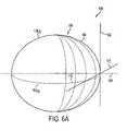
- FIG. 6Ais a representation of a Javal arc movement sphere.
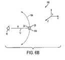
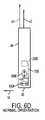
- FIG. 6Brepresents the portable electronic device in centered position on the Javal arc of motion as applied to the present invention.
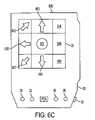
- FIG. 6Crepresents the screen of a sample at position in FIG. 6B .
- FIG. 6Drepresents a detailed view of the PDA at the position in FIG. 6B .
- FIG. 7Arepresents the portable electronic device above the horizontal axis of view position on the vertical Javal arc of motion as applied to the present invention.
- FIG. 7Brepresents the screen of a sample PDA at position in FIG. 7A .
- FIG. 7Crepresents a side view of the PDA of FIGS. 7A-7B .
- FIG. 8Arepresents the portable electronic device below the horizontal axis of view position on the vertical Javal arc of motion as applied to the present invention.
- FIG. 8Brepresents the screen of a sample PDA at position in FIG. 8A
- FIG. 8Crepresents a side view of the PDA of FIGS. 8A-8B .
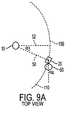
- FIG. 9Arepresents the portable electronic device to the right the vertical axis of view position on the horizontal Javal arc of motion as applied to the present invention.
- FIG. 9Brepresents the screen of a sample PDA at position in FIG. 9A .
- FIG. 9Crepresents a perspective view of the PDA of FIGS. 9A-9B .
- FIG. 10Arepresents the portable electronic device to the left the vertical axis of view position on the horizontal Javal arc of motion as applied to the present invention.
- FIG. 10Brepresents the screen of a sample PDA at position in FIG. 10A .
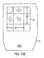
- FIG. 11Arepresents the portable electronic device to the left the vertical axis of view position on the horizontal Javal arc of motion as applied to the present invention.
- FIG. 11Brepresents the screen of a sample PDA at position in FIG. 11A .
- FIG. 12is the representative diagram of the motion and position logic in a preferred embodiment of the invention.
- FIG. 13is the method by which the movement of the display on the portable electronic device is calculated in the control unit.
- FIG. 14is an alternate method for calculating movement and position in an embodiment of the present invention with regard to the zoom function.
- FIG. 15is the resulting content screen for the method depicted in FIG. 14 .
- the Javal arcis mainly used in connection with optical measurement devices and it is generally used as a medical term. However, since the display of a computer or electronic device has to do with vision, the Javal arc can be applied to the system of screen display viewing as well. Javal was a French physician who developed measurements for lines of sight, which has been applied mainly to opthamalogic devices for almost a century. However, the Javal arc can be used to measure the natural motion of lines of sight and motion related thereto. In the present invention the Javal arc is used as a computational assumption or a constant in order to eliminate expensive accelerometers and valuable computing power in a portable electronic device. There are 3 components to the Javal arc that extends out from the comfortably stretched arm of the user.
- a simpler and more accurate method of the present inventionteaches a way to more accurately calculate movement from less expensive components, such as magnetometers.
- this control methodrequires only one accelerometer, and two inexpensive magnetometers.
- two inexpensive magnetometers and a gyroscopemay be used in the place of an accelerometer.
- a small portable display screenwill not have the capacity to display an entire desktop computer screen worth of graphics and text at one time.
- some solutionslike for those on PDAs have proposed a new set of display requirements, such as web clipping, which are wholly inadequate to display the graphics of a normal computer display.
- the inventionteaches a way to control the buffered display of an entire virtual display which will not fit on the display screen of the device, using the Javal arc motion and related computation aspects described herein.
- Control of the display 26 of the portable electronic device 20will be effectuated by motion of the device by a user. This is described above in the prior art description of control of the display of a device through a motion of the user. However, the user of a portable electronic device will not move the device equivalent to a normal Cartesian set of coordinates, or any other perfectly ordered geometrical system (cylindrical, etc.). The user will move the device in a manner that is natural to the user's eye and hand coordination, and is described with respect to a Javal arc movement coordinate system.
- FIG. 4is the representation of the virtual display space to the content display as converted in the present invention.
- virtual screenis a related concept to virtual display space, but is more limited in that the virtual screen has the equivalent virtual display space of only one desktop screen.
- the present inventiondistinguishes between virtual display space and a virtual screen, because of the manner in which the display memory will store and access such data.
- a PDA graphic memorymay store an entire virtual screen in a easily accessed buffer, but other screens are stored in cache or loaded as they become needed in the buffer.
- a more powerful device with a larger display buffermay be able to load an entire document.
- the expression virtual display spaceis primarily used. When discussing content from the Internet or an equivalent computer display, the expression virtual screen may be used but is distinguished from virtual display space.
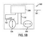
- the PDA 20includes a single or series of microprocessors and controllers represented by 500 , which may include a graphic memory buffer 501 for a virtual display.
- the fixed sphere motion control system 1000comprises an accelerometer 1002 one or more magnetometers 1004 and 1006 , an electrical signal connector 1100 and motion and position calculation logic 2000 .
- the fixed motion control system 1000is coupled with the control system of the PDA 20 through a series of logical connects 1001 .
- FIG. 5Bis the fixed motion control system 1000 in greater detail.
- the locus of a user 10is generally where they would be viewing, so approximately at the eye.
- a preferred distance R along the radial axis 12is usually between 35-40 cm from the user locus 10 .
- the radial axis 12may vary with user preferences and other factors such as the height of the user or the preference of the viewing distance of the device (which is adjustable in a preferred embodiment).
- the vertical component of the Javal arc 104will move along the primary axis of a fictional vertical ellipse 104 , that will be nearly circular in form.
- the center of the vertical ellipse 106will be close to the user locus 10 , but not necessarily because of variations in movements of the PDA 20 .
- the horizontal Javal arc 110will be located on fictional horizontal ellipse 112 , which as the vertical ellipse 104 will have its locus.
- the “panning” motion of the portable electronic device 20will generally travel on a portion of a spheroid 101 like coordinate system 100 in which the two Javal arcs which meet at the central viewing point 199 and define the surface of motion in which the user moves the device.
- the userdoes not need to move the device along either of the arcs 104 110 to effectuate control of the display of the device but will tend to move the device anywhere on the surface of the spheroid 101 .
- the angle of the movement along either arc 104 110will be proportional the angle that the user 10 is holding the device 20 away from its normal axis. These angles are described in detail below.
- FIGS. 6B-11Ca system for controlling the displayed portion 26 of a virtual display 99 which may be stored or rendered in the memory buffer 501 (or other control commands) of the portable electronic device 20 by calculating the movement of the device 20 is displayed and each corresponding content screen 600 resulting from the movement or repositioning.
- the present inventionuses the angle(s) of the device from the normal as a method for determining the distance traveled in the vertical direction. This is exemplified in the sequence of illustrations from FIG. 6B-11C .
- the user 10is holding the device 20 a radial distance 12 from the user's origin of vision or other reference point straight out from the user 10 .
- the PDA 20is not tilted at an angle because there has been no movement along the Javal arcs 104 and 110 .
- FIG. 6Ca corresponding content display 600 located on the portable electronic device 20 display 26 is shown.
- the content screen 600is divided up into 9 central regions 601 - 609 , including a central region 601 .
- the content screen 600is centered at its initial state.
- the content screen 600could start at another orientation or initial location.
- FIG. 6Dis a depiction of the PDA 20 side view when located at point 199 , with the component parts represented.
- FIG. 7Athe user 10 is holding the portable electronic device 20 at an angle ⁇ ( 1 ) 30 above the vertical normal of the user's line of sight 12 along the horizontal axis (or above the horizontal axis straight in front of the user).
- the PDA 20is held at angle ⁇ ( 1 ) 30
- itwill be naturally held at a second angle ⁇ ( 2 ) 40 at which the vertical axis of the portable electronic device 41 will make with the normal vertical 42 .
- FIG. 7CThe present invention takes advantage of the fact that generally ⁇ ( 1 ) 30 will be proportional to ⁇ ( 2 ) 40 as will be explained in the position and motion logic below.
- the corresponding screen to position or motion represented in FIG. 7Ais represented in FIG.
- FIG. 8Athe user 10 is holding the portable electronic device 20 at an angle ⁇ ( 1 ) 30 below the vertical normal of the user's line of sight 12 along the horizontal axis
- the PDA 20is held at angle ⁇ ( 1 ) 30 , it will also be naturally held at a second angle ⁇ ( 2 ) 40 in the opposition direction of FIG. 7C and is illustrated in FIG. 8C .
- the corresponding screen to position or motion represented in FIG. 8Ais represented in FIG. 8B , where region 601 is now moved downward and a top region of the virtual display space 630 is represented.
- FIGS. 9A-B , and FIGS. 10A-Brepresent the horizontal movement of the device to the right and left of the vertical normal of the user's line of sight respectively comprising angle ⁇ ( 3 ) 50 along the horizontal Javal arc 110 .
- FIG. 9Bshows a region in content screen 600 to the user's right 640 and FIG. 10B shows a region to the user's right 650 on the content screen 600 .
- FIG. 11Arepresents a motion to both the right and above the respective vertical and horizontal axis which resulting in the display of the content screen 600 as shown in FIG. 11B and is located on the surface of the Javal spheroid 101 .
- FIG. 9Cis the representation of the ⁇ ( 4 ) 60 of the display device 20 to it normal horizontal axis 62 corresponding to the movement of the device 20 along the arc 110 in FIG. 9A .
- the inventionincludes logic means 2000 , which is shown in FIG. 12 herein, for calculating the distance the device has moved from a previous locations or orientation.
- Such logic 2000may be hardwire into a physical Application Specific Integrated Circuit (ASIC) 2001 , but is more like calculated on a distributed system where the commands can be activated reprogrammed by the hardware in the portable electronic device 20 .
- Logic meansincludes an accelerometer input 2100 , a first magnetometer input 2200 a second magnetometer input 2300 , an optional fourth motion detection input 2400 , a virtual motion calculation unit 2500 , and a display control signal unit 2700 .
- accelerometerscan effectively measure motion in one direction without integration, that one direction can be easily calculated, especially in the accelerometers most sensitive mode which is vertical because of the measure of gravity. Normally, to detect the motion in two directions, two accelerometers can be placed on a device, but this requires a great deal of integration which leads to enormous inaccuracies. In the present invention, the single accelerometer 1002 will measure the vertical movement or position of the portable electronic device 20 .
- Magnetometerscan also easily measure the angle of the device 20 relative to its normal orientation as depicted in FIGS. 7C , 8 C and 9 C.
- ⁇ ( 2 ) 40 and ⁇ ( 4 ) 60can be easily measured from the vertical 42 and horizontal 62 orientations of the device 20 .
- ⁇ ( 1 ) 30 and ⁇ ( 3 ) 50made respectively as the distance traveled along Javals arcs 104 and 110 .
- a reasonably priced magnetometer 1004can generally measure a few nanoTeslas (nT) of magnetic field changes. These magnetometers can therefore measure changes on the order of centimeters.
- the magnetometercan therefore measure an angle of device relative to its normal axis 42 due to change in magnetic field orientation.
- magnetometersThere are a variety of reasonable priced magnetometers available to consumers and the use of particular magnetometers may vary based on manufacturing requirements of the device 20 , but constitute thin film magnetometers in a preferred embodiment in the present invention. The operation of such magnetometers is well know to those skilled in the art and will not discussed here.
- the resulting voltage inputs to 2200 and 2300 from the magnetometers calculations of the changes in the magnetic field Hgenerally means that each axis of sensitivity of both H(x) and H(y) will have to be determined from H( ⁇ ) and H(//) based on the angles ⁇ ( 2 ) 40 and ⁇ ( 4 ) 60 from the axes.
- the formula for the determination of the resulting voltage signal output into the inputs 2200 and 2300is included herein.
- the entire motion detection logic and control system 2000is virtual, and any one of the components of the system may be located at any place through out the hardware of the device 20 .
- the accelerometer input unit 2100may actually be located on the accelerometer 1002 instead of in the ASIC 2001 or in a discrete location in the distributed system alternative.
- the logic of the motion calculation unit 2500 for determining the motion and position of the device ofis based on formulas disclosed herein.
- V(x)R*d ⁇ ( 1 )/dt
- V(y)R*sin ⁇ ( 1 )*d ⁇ ( 2 )/dt in the “portrait” orientation
- V(x)R*d ⁇ (4)/dt
- V(y)R*sin ⁇ ( 1 )*d ⁇ ( 3 )/dt in the “landscape” orientation.
- step 1302the user activates the Javal arc movement control modes by one of several different methods and a voltage output from the accelerometer 1002 and the magnetometers 1004 and 1006 is sent to their respective virtual processors 2100 , 2200 and 2300 in the motion control logic 2000 .
- step 1304the motion and position of the device is determined by the motion calculation unit 2500 . This process described in greater detail below. The motion of the device is determined and then sent to the display control unit 2700 in step 1306 .
- the display control unit 2700determines what the particular motion or position of the device means for the control of the display in step 1306 , and in step 1308 will test for validity (if the motion indicates any kind of control at all) or if more input from the motion sensors 1002 1004 1006 needs to take place before change in the display will result. If more information is needed the control unit 2700 returns to step 1302 for further input. If not the particular display command (scroll up 20 pixels, pan left 50 pixels, etc.) is chosen by the display control unit 2700 in step 1310 . In step 1312 the command is sent to the display driver, which may included the virtual display 99 rendered in the display buffer 501 . If the command is valid in step 1314 , the command is performed in step 1320 , but if the command is not valid (for example the display has panned as far left as it can go) then the process returns to step 1310 or 1302 for another command.
- the movement and position of the devicecan be programmed to control the display differently. For example a user may wish to have the upward movement along the vertical Javal arc 104 to have the PDA content screen 600 to pan downward. Other users may wish to have such movement pan upward in an alternate embodiment.
- means for detecting the distance a user 10 is away from the devicemay include echo location functions, light intensity functions. Zooming functions may be activated in different ways depending on the efficiency of manufacture.
- Other useful features of the inventionmay include such embodiments which include (1) threshold control for the elimination of the movement “noise;” (2) threshold control for the activation of the display control mechanism, (3) alternate display controls, such as horizontal movement is a display vertical scroll and vice versa; (4) lock and unlock controls of the arc movement navigation (where the horizontal is locked, but the vertical continues to scroll) and other useful navigation features.
- the inventionuses the angle method for determining the users hand position, based upon some assumptions of human anatomy are used to determine the zoom control of the device 20 .
- the user 10is holding the PDA and wishing to enable the zoom-in and zoom-out functions.
- the user 10release the navigation mode (it is possible to stay in navigation if it is latched-mode operation), and press the zoom button 38 .
- the PDA 20is moved in and out from the user's eyes.
- the angle of the PDA 20changes from vertical to tilted angle ⁇ ( 5 ) 75 .
- ⁇ ( 5 ) 75can be used for scrolling.
- the device frameis related to the global frame by three successive rotations.
- ⁇ right arrow over ( ⁇ ) ⁇ ⁇ 1Cos ⁇ ⁇ 1 ⁇ right arrow over ( ⁇ ) ⁇ X′′′ +Sin ⁇ ⁇ 1 ⁇ right arrow over ( ⁇ ) ⁇ Y′′′ (9.1)
- ⁇ right arrow over ( ⁇ ) ⁇ ⁇ 2Cos ⁇ ⁇ 2 ⁇ right arrow over ( ⁇ ) ⁇ X′′′ +Sin ⁇ ⁇ 2 ⁇ right arrow over ( ⁇ ) ⁇ Y′′′ (9.2)
- V ⁇ 1V ⁇ 1 0 +S ⁇ 1 ⁇ right arrow over (g) ⁇ right arrow over ( ⁇ ) ⁇ ⁇ 1 (10.1)
- V ⁇ 2V ⁇ 2 0 +S ⁇ 2 ⁇ right arrow over ( ⁇ ) ⁇ ⁇ 2 (10.2)
- ⁇ ⁇ 1⁇ right arrow over (g) ⁇ ⁇ (Cos ⁇ ⁇ 1 ⁇ right arrow over ( ⁇ ) ⁇ X′′′ +Sin ⁇ ⁇ 1 ⁇ right arrow over ( ⁇ ) ⁇ Y′′′ ) (12.1)
Landscapes
- Engineering & Computer Science (AREA)
- Computer Hardware Design (AREA)
- Theoretical Computer Science (AREA)
- Human Computer Interaction (AREA)
- Physics & Mathematics (AREA)
- General Engineering & Computer Science (AREA)
- General Physics & Mathematics (AREA)
- User Interface Of Digital Computer (AREA)
Abstract
Description
- 1) The user will maintain the display at a distance that is constant. The distance can be adjusted to a comforatable reading distance. Assume that the comfortable reading distance is denoted by the value Rcomf.
- 2) The user will maintain the display approximately normal to his line of sight.
- 1) in portrait orientation:
- 2) in landscape orientation: γ=±π/2
{right arrow over (μ)}α=Cos ξα{right arrow over (μ)}X′″+Sin ξα{right arrow over (μ)}Y′″ (5)
{right arrow over (μ)}α1=Cos ξα1{right arrow over (μ)}X′″+Sin ξα1{right arrow over (μ)}Y′″ (9.1)
{right arrow over (μ)}α2=Cos ξα2{right arrow over (μ)}X′″+Sin ξα2{right arrow over (μ)}Y′″ (9.2)
Vα1=Vα10+Sα1{right arrow over (g)}·{right arrow over (μ)}α1 (10.1)
Vα2=Vα20+Sα2·{right arrow over (μ)}α2 (10.2)
Where the offset voltage Vα0(in V), and the sensitivities Sα (in V m−1, δ), are assumed to be known (calibration).
γα1={right arrow over (g)}·(Cos ξα1{right arrow over (μ)}X′″+Sin ξα1{right arrow over (μ)}Y′″) (12.1)
γα2={right arrow over (g)}·(Cos ξα2{right arrow over (μ)}X′″+Sin ξα2{right arrow over (μ)}Y′″) (12.2)
i.e.,
Cos ξα1({right arrow over (g)}{right arrow over (μ)}X′″)+Sin ξα1({right arrow over (g)}{right arrow over (μ)}Y′″)=γα1
Cos ξα2({right arrow over (g)}{right arrow over (μ)}X′″)+Sin ξα2({right arrow over (g)}{right arrow over (μ)}Y′″)=γα2
i.e.,
γX′″={right arrow over (g)}{right arrow over (μ)}X′″
γY′″={right arrow over (g)}{right arrow over (μ)}Y′″ (14)
{right arrow over (μ)}X′″=Cos γ{right arrow over (μ)}X″+Sin γ{right arrow over (μ)}Y″
{right arrow over (μ)}Y′″=−Sin γ{right arrow over (μ)}X″+Cos γ{right arrow over (μ)}Y″ (15)
{right arrow over (μ)}X″=Cos θ{right arrow over (μ)}X′ Sin θ{right arrow over (μ)}Z′
{right arrow over (μ)}Y″={right arrow over (μ)}Y′
and{right arrow over (g)}=−{right arrow over (μ)}Z′ (17)
γX′″=+gCos γ Sin θ (18.1)
γY′″=−gSin γ Sin θ (18.2)
i.e.,
i.e.,
i.e.,
and
for portrait orientation
for landscape orientation with ε=Sig (Sin γ)
{right arrow over (H)}″=(HpocCos δ){right arrow over (μ)}X (23)
Where the amplitude Hpocand the inclination angle δ may be slowly varying functions off position and time.
{right arrow over (H)}⊥=(−HpocSin δ){right arrow over (μ)}Z (24)
{right arrow over (μ)}M1=Cos ξM1{right arrow over (μ)}X′″+Sin ξM1{right arrow over (μ)}Y′″ (25.1)
{right arrow over (μ)}M2=Cos ξM1{right arrow over (μ)}X′″+Sin ξM2{right arrow over (μ)}Y′″ (25.2)
And the output of these two sensors are given by:
VM1=V0M1+SM1{{right arrow over (H)}//·{right arrow over (μ)}M1+{right arrow over (H)}⊥·{right arrow over (μ)}M1} (26.1)
VM2=V0M2+SM2{{right arrow over (H)}//·{right arrow over (μ)}M2+{right arrow over (H)}⊥·{right arrow over (μ)}M2} (26.2)
Where the offset voltage V0α (in V), and the sensitivities Sα (in V·Oe−1) are assumed to be known (calibration).
i.e., from (15), one has:
i.e.,
hX′″=({right arrow over (H)}//+{right arrow over (H)}⊥)·{right arrow over (μ)}X′″ (30.1)
hY′″=({right arrow over (H)}//+{right arrow over (H)}⊥)·{right arrow over (μ)}Y′″ (30.2)
{right arrow over (μ)}X′″=Cos γ Cos θ Cos Φ{right arrow over (μ)}X+Cos γ Cos θ Sin Φ{right arrow over (μ)}Y
Cos γ Sin θ{right arrow over (μ)}Z−Sin γ Sin Φ{right arrow over (μ)}X+Sin γ Cos Φ{right arrow over (μ)}Y=(Cos γ Cos θ Cos Φ−Sin γ
Sin Φ){right arrow over (μ)}X+A{right arrow over (μ)}Y−Cos γ Sin θ{right arrow over (μ)}Z (31.1)
{right arrow over (μ)}Y′″=(Sin γ Cos θ Cos Φ−Cos γ Sin Φ){right arrow over (μ)}X+B{right arrow over (μ)}Y−Sin γ Sin θ{right arrow over (μ)}Z (31.2)
i.e.,
hX′″=H//(Cos γ Cos θ Cos Φ−Sin γ Sin Φ)−H⊥ Cos γSin θ (32.1)
hy′″=H//(Sin γ Cos θ Cos Φ−Cos γ Sin Φ)+H⊥ Sin γ Sin θ (32.2)
Therefore Cos θ=ε(1−Sin2θ)1/2 (33)
ε Cos γ|Cos θ|(H//Cos Φ)−Sin γ(H//Sin Φ)=[hx′″−H⊥ Cos γ Sin θ]
ε Sin γ|Cos θ|(H//Cos Φ)−Cos γ(H//Sin Φ)=[hy′″−H⊥ Sin γ Sin θ]
i.e.,
hX′″=ε Cos γ|Cos θ|(H//Cos Φ)−Sin γ(H//Sin Φ)+H⊥ Cos γ Sin θ (35.1)
hY′″=ε Sin γ|Cos θ|(H//Cos Φ)−Cos γ(H//Sin Φ)+H⊥ Sin γ Sin θ (35.2)
Sin γhX′″−Cos γhY′″=2ε Sin γ Cos γ|Cos θ|(H//Cos Φ)−Cos2γ Sin2γ(H//Sin Φ)
Sin γhX′″+Cos γhY′″=−(H//Sin Φ)+2H⊥ Sin γ Cos γ Sin θ
i.e.,
2ε Sin γ Cos γ|Cos θ|(H//Cos Φ)+Cos2γ Sin2γ(H//Sin Φ)=(Sin γhX′″−Cos γhY′″) (36.1)
(H//Sin Φ)+(2 Sin γ Cos γ Sin θ)H⊥=(Sin γhX′″+Cos γhY′″) (36.2)
H⊥=εM(1−H//2)1/2 (37)
Where εMis known (north or south of magnetic equator).
2ε Sin γ Cos γ|Cos θ|(H//Cos Φ)+(Cos2γ−Sin2γ)(H//Sin Φ)=(Sin γhX′″−Cos γhY′″) (38.1)
(H//Sin Φ)+εM(Sin γ Cos γ Sin θ)(Hpoc2−H//2)1/2=(Sin γhX′″+Cos γhY′″) (38.2)
If the magnetic inclination δ and the field amplitude Hpocare assumed to be known:
H//=HpocCos δ (9.1)
H⊥=HpocSin δ (39.2)
[2H//Sin γ Cos γ(ε|Cos θ|)]Cos Φ+(Cos2γ−Sin2γ)(H//Sin Φ)=(Sin γhX′″−Cos γhY′″) (40.1)
H//Sin Φ+2(Sin γ Cos γ Sin θ)H⊥=(Sin γhX′″+Cos γhY′″) (40.2)
i.e.,
H//Sin Φ=2(Sin γ Cos γ Sin θ)H⊥−(Sin γhX′″+Cos γhY′″) (41.1)
γ≃0 then H//Sin Φ≃Cos γhY′″
hX′″≃ε|Cos θ|(H//Cos Φ)+H⊥ Sin θ
i.e.,
ε|Cos θ|(H//Cos Φ)≃(hX′″−H⊥ Sin θ)
(Cos γhX′″−Sin γhy′″)=ε|Cos θ|(H//Cos Φ)+(Cos2γ−Sin2γ)H⊥ Sin θ
(Sin γhX′″+Cos γhy′″=−(H//Sin Φ)+2(Sin γ Cos γ)H⊥ Sin θ
i.e.,
ε|Cos θ|(H//Cos Φ)+(Cos2γ−Sin2γ)(H⊥ Sin Φ)=(Cos γhX′″−Sin θhy′″) (42.1)
−(H//Sin Φ)+2(Sin γ Cos γ)(H⊥ Sin θ)=(Sin γhX′″+Cos γhy′″) (42.2)
If γ=0, one has in first approximation:
ε|Cos θ|(H//Cos Φ)+(H⊥ Sin θ)=hx′″
−H//Sin Φ=hy′″
i.e.,
i.e.,
Claims (19)
Priority Applications (2)
| Application Number | Priority Date | Filing Date | Title |
|---|---|---|---|
| US10/775,762US7365734B2 (en) | 2002-08-06 | 2004-02-09 | Control of display content by movement on a fixed spherical space |
| US14/831,870USRE47457E1 (en) | 2001-08-07 | 2015-08-20 | Control of display content by movement on a fixed spherical space |
Applications Claiming Priority (3)
| Application Number | Priority Date | Filing Date | Title |
|---|---|---|---|
| WOPCT/US02/24981 | 2002-08-06 | ||
| PCT/US2002/024981WO2003015072A1 (en) | 2001-08-07 | 2002-08-06 | Control of display content by movement on a fixed spherical space |
| US10/775,762US7365734B2 (en) | 2002-08-06 | 2004-02-09 | Control of display content by movement on a fixed spherical space |
Related Parent Applications (1)
| Application Number | Title | Priority Date | Filing Date |
|---|---|---|---|
| PCT/US2002/024981ContinuationWO2003015072A1 (en) | 2001-08-07 | 2002-08-06 | Control of display content by movement on a fixed spherical space |
Related Child Applications (1)
| Application Number | Title | Priority Date | Filing Date |
|---|---|---|---|
| US14/831,870ReissueUSRE47457E1 (en) | 2001-08-07 | 2015-08-20 | Control of display content by movement on a fixed spherical space |
Publications (2)
| Publication Number | Publication Date |
|---|---|
| US20040227742A1 US20040227742A1 (en) | 2004-11-18 |
| US7365734B2true US7365734B2 (en) | 2008-04-29 |
Family
ID=33418982
Family Applications (1)
| Application Number | Title | Priority Date | Filing Date |
|---|---|---|---|
| US10/775,762CeasedUS7365734B2 (en) | 2001-08-07 | 2004-02-09 | Control of display content by movement on a fixed spherical space |
Country Status (1)
| Country | Link |
|---|---|
| US (1) | US7365734B2 (en) |
Cited By (43)
| Publication number | Priority date | Publication date | Assignee | Title |
|---|---|---|---|---|
| US20020109673A1 (en)* | 2001-01-04 | 2002-08-15 | Thierry Valet | Method and apparatus employing angled single accelerometer sensing multi-directional motion |
| US20060061551A1 (en)* | 1999-02-12 | 2006-03-23 | Vega Vista, Inc. | Motion detection and tracking system to control navigation and display of portable displays including on-chip gesture detection |
| US20060061550A1 (en)* | 1999-02-12 | 2006-03-23 | Sina Fateh | Display size emulation system |
| US20060103631A1 (en)* | 2004-11-18 | 2006-05-18 | Konica Minolta Photo Imaging, Inc. | Electronic device and pointing representation displaying method |
| US20060238502A1 (en)* | 2003-10-28 | 2006-10-26 | Katsuhiro Kanamori | Image display device and image display method |
| US20060279542A1 (en)* | 1999-02-12 | 2006-12-14 | Vega Vista, Inc. | Cellular phones and mobile devices with motion driven control |
| US20070061077A1 (en)* | 2005-09-09 | 2007-03-15 | Sina Fateh | Discrete inertial display navigation |
| US20070057911A1 (en)* | 2005-09-12 | 2007-03-15 | Sina Fateh | System and method for wireless network content conversion for intuitively controlled portable displays |
| US20120229447A1 (en)* | 2011-03-08 | 2012-09-13 | Nokia Corporation | Apparatus and associated methods |
| US8471869B1 (en) | 2010-11-02 | 2013-06-25 | Google Inc. | Optimizing display orientation |
| US20130249895A1 (en)* | 2012-03-23 | 2013-09-26 | Microsoft Corporation | Light guide display and field of view |
| US8643951B1 (en) | 2012-03-15 | 2014-02-04 | Google Inc. | Graphical menu and interaction therewith through a viewing window |
| US8797358B1 (en)* | 2010-11-02 | 2014-08-05 | Google Inc. | Optimizing display orientation |
| US8994694B2 (en) | 2011-11-30 | 2015-03-31 | Blackberry Limited | Optical interference based user input device |
| US20150130709A1 (en)* | 2013-11-14 | 2015-05-14 | Jfe Systems, Inc. | Gesture detecting device, gesture recognition device |
| US9035878B1 (en) | 2012-02-29 | 2015-05-19 | Google Inc. | Input system |
| US9223138B2 (en) | 2011-12-23 | 2015-12-29 | Microsoft Technology Licensing, Llc | Pixel opacity for augmented reality |
| US9297996B2 (en) | 2012-02-15 | 2016-03-29 | Microsoft Technology Licensing, Llc | Laser illumination scanning |
| US9304235B2 (en) | 2014-07-30 | 2016-04-05 | Microsoft Technology Licensing, Llc | Microfabrication |
| US9368546B2 (en) | 2012-02-15 | 2016-06-14 | Microsoft Technology Licensing, Llc | Imaging structure with embedded light sources |
| US9372347B1 (en) | 2015-02-09 | 2016-06-21 | Microsoft Technology Licensing, Llc | Display system |
| US9423360B1 (en) | 2015-02-09 | 2016-08-23 | Microsoft Technology Licensing, Llc | Optical components |
| US9429692B1 (en) | 2015-02-09 | 2016-08-30 | Microsoft Technology Licensing, Llc | Optical components |
| US9442517B2 (en) | 2011-11-30 | 2016-09-13 | Blackberry Limited | Input gestures using device movement |
| US9513480B2 (en) | 2015-02-09 | 2016-12-06 | Microsoft Technology Licensing, Llc | Waveguide |
| US9535253B2 (en) | 2015-02-09 | 2017-01-03 | Microsoft Technology Licensing, Llc | Display system |
| US9558590B2 (en) | 2012-03-28 | 2017-01-31 | Microsoft Technology Licensing, Llc | Augmented reality light guide display |
| US9578318B2 (en) | 2012-03-14 | 2017-02-21 | Microsoft Technology Licensing, Llc | Imaging structure emitter calibration |
| US9581820B2 (en) | 2012-06-04 | 2017-02-28 | Microsoft Technology Licensing, Llc | Multiple waveguide imaging structure |
| US9606586B2 (en) | 2012-01-23 | 2017-03-28 | Microsoft Technology Licensing, Llc | Heat transfer device |
| US9717981B2 (en) | 2012-04-05 | 2017-08-01 | Microsoft Technology Licensing, Llc | Augmented reality and physical games |
| US9726887B2 (en) | 2012-02-15 | 2017-08-08 | Microsoft Technology Licensing, Llc | Imaging structure color conversion |
| US9779643B2 (en) | 2012-02-15 | 2017-10-03 | Microsoft Technology Licensing, Llc | Imaging structure emitter configurations |
| US9827209B2 (en) | 2015-02-09 | 2017-11-28 | Microsoft Technology Licensing, Llc | Display system |
| US10018844B2 (en) | 2015-02-09 | 2018-07-10 | Microsoft Technology Licensing, Llc | Wearable image display system |
| US10192358B2 (en) | 2012-12-20 | 2019-01-29 | Microsoft Technology Licensing, Llc | Auto-stereoscopic augmented reality display |
| US10191515B2 (en) | 2012-03-28 | 2019-01-29 | Microsoft Technology Licensing, Llc | Mobile device light guide display |
| US10254942B2 (en) | 2014-07-31 | 2019-04-09 | Microsoft Technology Licensing, Llc | Adaptive sizing and positioning of application windows |
| US10317677B2 (en) | 2015-02-09 | 2019-06-11 | Microsoft Technology Licensing, Llc | Display system |
| US10502876B2 (en) | 2012-05-22 | 2019-12-10 | Microsoft Technology Licensing, Llc | Waveguide optics focus elements |
| US10592080B2 (en) | 2014-07-31 | 2020-03-17 | Microsoft Technology Licensing, Llc | Assisted presentation of application windows |
| US10678412B2 (en) | 2014-07-31 | 2020-06-09 | Microsoft Technology Licensing, Llc | Dynamic joint dividers for application windows |
| US11086216B2 (en) | 2015-02-09 | 2021-08-10 | Microsoft Technology Licensing, Llc | Generating electronic components |
Families Citing this family (8)
| Publication number | Priority date | Publication date | Assignee | Title |
|---|---|---|---|---|
| TWI233743B (en)* | 2004-03-05 | 2005-06-01 | Benq Corp | Hand-held electronic device and input method thereof |
| US8842070B2 (en)* | 2004-03-17 | 2014-09-23 | Intel Corporation | Integrated tracking for on screen navigation with small hand held devices |
| US20060061545A1 (en)* | 2004-04-02 | 2006-03-23 | Media Lab Europe Limited ( In Voluntary Liquidation). | Motion-activated control with haptic feedback |
| FI119746B (en)* | 2004-06-24 | 2009-02-27 | Nokia Corp | Control of an electronic device |
| EP1806643B1 (en) | 2006-01-06 | 2014-10-08 | Drnc Holdings, Inc. | Method for entering commands and/or characters for a portable communication device equipped with a tilt sensor |
| WO2008145682A1 (en)* | 2007-05-31 | 2008-12-04 | Bang & Olufsen A/S | A multi media controller |
| JP2010092086A (en)* | 2008-10-03 | 2010-04-22 | Just Syst Corp | User input apparatus, digital camera, input control method, and input control program |
| IT201900019037A1 (en) | 2019-10-16 | 2021-04-16 | St Microelectronics Srl | PERFECTED METHOD FOR DETECTING A WRIST TILT GESTURE AND ELECTRONIC UNIT AND WEARABLE ELECTRONIC DEVICE IMPLEMENTING THE SAME |
Citations (9)
| Publication number | Priority date | Publication date | Assignee | Title |
|---|---|---|---|---|
| US5506605A (en)* | 1992-07-27 | 1996-04-09 | Paley; W. Bradford | Three-dimensional mouse with tactile feedback |
| US5602566A (en)* | 1993-08-24 | 1997-02-11 | Hitachi, Ltd. | Small-sized information processor capable of scrolling screen in accordance with tilt, and scrolling method therefor |
| US6072467A (en)* | 1996-05-03 | 2000-06-06 | Mitsubishi Electric Information Technology Center America, Inc. (Ita) | Continuously variable control of animated on-screen characters |
| US6184847B1 (en)* | 1998-09-22 | 2001-02-06 | Vega Vista, Inc. | Intuitive control of portable data displays |
| US6201554B1 (en)* | 1999-01-12 | 2001-03-13 | Ericsson Inc. | Device control apparatus for hand-held data processing device |
| US6288704B1 (en)* | 1999-06-08 | 2001-09-11 | Vega, Vista, Inc. | Motion detection and tracking system to control navigation and display of object viewers |
| US6466198B1 (en)* | 1999-11-05 | 2002-10-15 | Innoventions, Inc. | View navigation and magnification of a hand-held device with a display |
| US6690358B2 (en)* | 2000-11-30 | 2004-02-10 | Alan Edward Kaplan | Display control for hand-held devices |
| US6847351B2 (en)* | 2001-08-13 | 2005-01-25 | Siemens Information And Communication Mobile, Llc | Tilt-based pointing for hand-held devices |
- 2004
- 2004-02-09USUS10/775,762patent/US7365734B2/ennot_activeCeased
Patent Citations (9)
| Publication number | Priority date | Publication date | Assignee | Title |
|---|---|---|---|---|
| US5506605A (en)* | 1992-07-27 | 1996-04-09 | Paley; W. Bradford | Three-dimensional mouse with tactile feedback |
| US5602566A (en)* | 1993-08-24 | 1997-02-11 | Hitachi, Ltd. | Small-sized information processor capable of scrolling screen in accordance with tilt, and scrolling method therefor |
| US6072467A (en)* | 1996-05-03 | 2000-06-06 | Mitsubishi Electric Information Technology Center America, Inc. (Ita) | Continuously variable control of animated on-screen characters |
| US6184847B1 (en)* | 1998-09-22 | 2001-02-06 | Vega Vista, Inc. | Intuitive control of portable data displays |
| US6201554B1 (en)* | 1999-01-12 | 2001-03-13 | Ericsson Inc. | Device control apparatus for hand-held data processing device |
| US6288704B1 (en)* | 1999-06-08 | 2001-09-11 | Vega, Vista, Inc. | Motion detection and tracking system to control navigation and display of object viewers |
| US6466198B1 (en)* | 1999-11-05 | 2002-10-15 | Innoventions, Inc. | View navigation and magnification of a hand-held device with a display |
| US6690358B2 (en)* | 2000-11-30 | 2004-02-10 | Alan Edward Kaplan | Display control for hand-held devices |
| US6847351B2 (en)* | 2001-08-13 | 2005-01-25 | Siemens Information And Communication Mobile, Llc | Tilt-based pointing for hand-held devices |
Cited By (53)
| Publication number | Priority date | Publication date | Assignee | Title |
|---|---|---|---|---|
| US20060061551A1 (en)* | 1999-02-12 | 2006-03-23 | Vega Vista, Inc. | Motion detection and tracking system to control navigation and display of portable displays including on-chip gesture detection |
| US20060061550A1 (en)* | 1999-02-12 | 2006-03-23 | Sina Fateh | Display size emulation system |
| US20060279542A1 (en)* | 1999-02-12 | 2006-12-14 | Vega Vista, Inc. | Cellular phones and mobile devices with motion driven control |
| US20020109673A1 (en)* | 2001-01-04 | 2002-08-15 | Thierry Valet | Method and apparatus employing angled single accelerometer sensing multi-directional motion |
| US20060238502A1 (en)* | 2003-10-28 | 2006-10-26 | Katsuhiro Kanamori | Image display device and image display method |
| US20060103631A1 (en)* | 2004-11-18 | 2006-05-18 | Konica Minolta Photo Imaging, Inc. | Electronic device and pointing representation displaying method |
| US20070061077A1 (en)* | 2005-09-09 | 2007-03-15 | Sina Fateh | Discrete inertial display navigation |
| US7647175B2 (en) | 2005-09-09 | 2010-01-12 | Rembrandt Technologies, Lp | Discrete inertial display navigation |
| US20070057911A1 (en)* | 2005-09-12 | 2007-03-15 | Sina Fateh | System and method for wireless network content conversion for intuitively controlled portable displays |
| US8558851B1 (en)* | 2010-11-02 | 2013-10-15 | Google Inc. | Optimizing display orientation |
| US9035875B1 (en) | 2010-11-02 | 2015-05-19 | Google Inc. | Optimizing display orientation |
| US8471869B1 (en) | 2010-11-02 | 2013-06-25 | Google Inc. | Optimizing display orientation |
| US8797358B1 (en)* | 2010-11-02 | 2014-08-05 | Google Inc. | Optimizing display orientation |
| US20120229447A1 (en)* | 2011-03-08 | 2012-09-13 | Nokia Corporation | Apparatus and associated methods |
| US9035940B2 (en)* | 2011-03-08 | 2015-05-19 | Nokia Corporation | Apparatus and associated methods |
| US9442517B2 (en) | 2011-11-30 | 2016-09-13 | Blackberry Limited | Input gestures using device movement |
| US8994694B2 (en) | 2011-11-30 | 2015-03-31 | Blackberry Limited | Optical interference based user input device |
| US9223138B2 (en) | 2011-12-23 | 2015-12-29 | Microsoft Technology Licensing, Llc | Pixel opacity for augmented reality |
| US9606586B2 (en) | 2012-01-23 | 2017-03-28 | Microsoft Technology Licensing, Llc | Heat transfer device |
| US9779643B2 (en) | 2012-02-15 | 2017-10-03 | Microsoft Technology Licensing, Llc | Imaging structure emitter configurations |
| US9684174B2 (en) | 2012-02-15 | 2017-06-20 | Microsoft Technology Licensing, Llc | Imaging structure with embedded light sources |
| US9297996B2 (en) | 2012-02-15 | 2016-03-29 | Microsoft Technology Licensing, Llc | Laser illumination scanning |
| US9726887B2 (en) | 2012-02-15 | 2017-08-08 | Microsoft Technology Licensing, Llc | Imaging structure color conversion |
| US9368546B2 (en) | 2012-02-15 | 2016-06-14 | Microsoft Technology Licensing, Llc | Imaging structure with embedded light sources |
| US9035878B1 (en) | 2012-02-29 | 2015-05-19 | Google Inc. | Input system |
| US9807381B2 (en) | 2012-03-14 | 2017-10-31 | Microsoft Technology Licensing, Llc | Imaging structure emitter calibration |
| US9578318B2 (en) | 2012-03-14 | 2017-02-21 | Microsoft Technology Licensing, Llc | Imaging structure emitter calibration |
| US8643951B1 (en) | 2012-03-15 | 2014-02-04 | Google Inc. | Graphical menu and interaction therewith through a viewing window |
| US11068049B2 (en)* | 2012-03-23 | 2021-07-20 | Microsoft Technology Licensing, Llc | Light guide display and field of view |
| US20130249895A1 (en)* | 2012-03-23 | 2013-09-26 | Microsoft Corporation | Light guide display and field of view |
| US9558590B2 (en) | 2012-03-28 | 2017-01-31 | Microsoft Technology Licensing, Llc | Augmented reality light guide display |
| US10388073B2 (en) | 2012-03-28 | 2019-08-20 | Microsoft Technology Licensing, Llc | Augmented reality light guide display |
| US10191515B2 (en) | 2012-03-28 | 2019-01-29 | Microsoft Technology Licensing, Llc | Mobile device light guide display |
| US10478717B2 (en) | 2012-04-05 | 2019-11-19 | Microsoft Technology Licensing, Llc | Augmented reality and physical games |
| US9717981B2 (en) | 2012-04-05 | 2017-08-01 | Microsoft Technology Licensing, Llc | Augmented reality and physical games |
| US10502876B2 (en) | 2012-05-22 | 2019-12-10 | Microsoft Technology Licensing, Llc | Waveguide optics focus elements |
| US9581820B2 (en) | 2012-06-04 | 2017-02-28 | Microsoft Technology Licensing, Llc | Multiple waveguide imaging structure |
| US10192358B2 (en) | 2012-12-20 | 2019-01-29 | Microsoft Technology Licensing, Llc | Auto-stereoscopic augmented reality display |
| US9261969B2 (en)* | 2013-11-14 | 2016-02-16 | Jfe Systems, Inc. | Gesture detecting device, gesture recognition device |
| US20150130709A1 (en)* | 2013-11-14 | 2015-05-14 | Jfe Systems, Inc. | Gesture detecting device, gesture recognition device |
| US9304235B2 (en) | 2014-07-30 | 2016-04-05 | Microsoft Technology Licensing, Llc | Microfabrication |
| US10592080B2 (en) | 2014-07-31 | 2020-03-17 | Microsoft Technology Licensing, Llc | Assisted presentation of application windows |
| US10254942B2 (en) | 2014-07-31 | 2019-04-09 | Microsoft Technology Licensing, Llc | Adaptive sizing and positioning of application windows |
| US10678412B2 (en) | 2014-07-31 | 2020-06-09 | Microsoft Technology Licensing, Llc | Dynamic joint dividers for application windows |
| US10317677B2 (en) | 2015-02-09 | 2019-06-11 | Microsoft Technology Licensing, Llc | Display system |
| US9372347B1 (en) | 2015-02-09 | 2016-06-21 | Microsoft Technology Licensing, Llc | Display system |
| US10018844B2 (en) | 2015-02-09 | 2018-07-10 | Microsoft Technology Licensing, Llc | Wearable image display system |
| US9423360B1 (en) | 2015-02-09 | 2016-08-23 | Microsoft Technology Licensing, Llc | Optical components |
| US9429692B1 (en) | 2015-02-09 | 2016-08-30 | Microsoft Technology Licensing, Llc | Optical components |
| US9535253B2 (en) | 2015-02-09 | 2017-01-03 | Microsoft Technology Licensing, Llc | Display system |
| US9827209B2 (en) | 2015-02-09 | 2017-11-28 | Microsoft Technology Licensing, Llc | Display system |
| US9513480B2 (en) | 2015-02-09 | 2016-12-06 | Microsoft Technology Licensing, Llc | Waveguide |
| US11086216B2 (en) | 2015-02-09 | 2021-08-10 | Microsoft Technology Licensing, Llc | Generating electronic components |
Also Published As
| Publication number | Publication date |
|---|---|
| US20040227742A1 (en) | 2004-11-18 |
Similar Documents
| Publication | Publication Date | Title |
|---|---|---|
| US7365734B2 (en) | Control of display content by movement on a fixed spherical space | |
| US11301196B2 (en) | Method, device and program for browsing information on a display | |
| US10318017B2 (en) | Viewing images with tilt control on a hand-held device | |
| US7958644B2 (en) | Orientation sensing in a multi part device | |
| US8866741B2 (en) | Method, medium and apparatus for browsing images | |
| JP5427240B2 (en) | User command input method and device based on motion sensing | |
| US7966146B2 (en) | Force sensing apparatus and method to determine the radius of rotation of a moving object | |
| JP4926424B2 (en) | Mobile device and drawing processing control method thereof | |
| US20140085341A1 (en) | Mobile device and method of changing screen orientation of mobile device | |
| US8810511B2 (en) | Handheld electronic device with motion-controlled cursor | |
| KR20020038950A (en) | A system and method utilizing motion input for manipulating a display of data | |
| JP2004288188A (en) | Pen-type input system using magnetic sensor and its trajectory restoration method | |
| USRE47457E1 (en) | Control of display content by movement on a fixed spherical space | |
| US20100268508A1 (en) | System and method for measuring tilt using lowest degrees of freedom of accelerometer | |
| US20170199585A1 (en) | Processing unit, computer program amd method to control a cursor on a screen according to an orientation of a pointing device | |
| WO2003015072A1 (en) | Control of display content by movement on a fixed spherical space | |
| US12164705B2 (en) | Dynamic gravity vector estimation for memory constrained devices | |
| US20020109673A1 (en) | Method and apparatus employing angled single accelerometer sensing multi-directional motion | |
| KR100387768B1 (en) | Virtual window control apparatus and control methods for portable electronic equipments | |
| JP2002175066A (en) | Display method and display device |
Legal Events
| Date | Code | Title | Description |
|---|---|---|---|
| AS | Assignment | Owner name:VEGA VISTA, INC., CALIFORNIA Free format text:ASSIGNMENT OF ASSIGNORS INTEREST;ASSIGNORS:FATEH, SINA;VALDES, RAY;MASIEWICZ, JOHN;REEL/FRAME:015554/0673;SIGNING DATES FROM 20040511 TO 20040610 | |
| AS | Assignment | Owner name:REMBRANDT TECHNOLOGIES, LP, PENNSYLVANIA Free format text:ASSIGNMENT OF ASSIGNORS INTEREST;ASSIGNOR:VEGA VISTA, INC.;REEL/FRAME:020119/0650 Effective date:20071018 | |
| STCF | Information on status: patent grant | Free format text:PATENTED CASE | |
| CC | Certificate of correction | ||
| AS | Assignment | Owner name:REMBRANDT PORTABLE DISPLAY TECHNOLOGIES, LP, VIRGI Free format text:ASSIGNMENT OF ASSIGNORS INTEREST;ASSIGNOR:REMBRANDT TECHNOLOGIES, LP;REEL/FRAME:024823/0018 Effective date:20100809 | |
| REMI | Maintenance fee reminder mailed | ||
| FPAY | Fee payment | Year of fee payment:4 | |
| SULP | Surcharge for late payment | ||
| AS | Assignment | Owner name:VEGA VISTA, INC., CALIFORNIA Free format text:PATENT ACQUISITION AGREEMENT;ASSIGNOR:REMBRANDT PORTABLE DISPLAY TECHNOLOGIES, LP;REEL/FRAME:028466/0229 Effective date:20120329 | |
| AS | Assignment | Owner name:FACEBOOK, INC., CALIFORNIA Free format text:ASSIGNMENT OF ASSIGNORS INTEREST;ASSIGNOR:VEGA VISTA, INC.;REEL/FRAME:033459/0341 Effective date:20140724 | |
| AS | Assignment | Owner name:FACEBOOK, INC., CALIFORNIA Free format text:ASSIGNMENT OF ASSIGNORS INTEREST;ASSIGNOR:VEGA VISTA, INC.;REEL/FRAME:033929/0813 Effective date:20140724 | |
| AS | Assignment | Owner name:OCULUS VR, LLC, CALIFORNIA Free format text:ASSIGNMENT OF ASSIGNORS INTEREST;ASSIGNOR:FACEBOOK, INC.;REEL/FRAME:036072/0771 Effective date:20150428 | |
| RF | Reissue application filed | Effective date:20150820 | |
| FPAY | Fee payment | Year of fee payment:8 | |
| AS | Assignment | Owner name:FACEBOOK, INC., CALIFORNIA Free format text:ASSIGNMENT OF ASSIGNORS INTEREST;ASSIGNOR:OCULUS VR, LLC;REEL/FRAME:037414/0781 Effective date:20151216 | |
| AS | Assignment | Owner name:META PLATFORMS, INC., CALIFORNIA Free format text:CHANGE OF NAME;ASSIGNOR:FACEBOOK, INC.;REEL/FRAME:058897/0824 Effective date:20211028 |