US7365444B2 - Active anti-islanding system and method - Google Patents
Active anti-islanding system and methodDownload PDFInfo
- Publication number
- US7365444B2 US7365444B2US11/563,333US56333306AUS7365444B2US 7365444 B2US7365444 B2US 7365444B2US 56333306 AUS56333306 AUS 56333306AUS 7365444 B2US7365444 B2US 7365444B2
- Authority
- US
- United States
- Prior art keywords
- engine
- power
- control system
- flow
- generator
- Prior art date
- Legal status (The legal status is an assumption and is not a legal conclusion. Google has not performed a legal analysis and makes no representation as to the accuracy of the status listed.)
- Expired - Lifetime
Links
Images


Classifications
- H—ELECTRICITY
- H02—GENERATION; CONVERSION OR DISTRIBUTION OF ELECTRIC POWER
- H02J—CIRCUIT ARRANGEMENTS OR SYSTEMS FOR SUPPLYING OR DISTRIBUTING ELECTRIC POWER; SYSTEMS FOR STORING ELECTRIC ENERGY
- H02J3/00—Circuit arrangements for AC mains or AC distribution networks
- H02J3/38—Arrangements for parallely feeding a single network by two or more generators, converters or transformers
- F—MECHANICAL ENGINEERING; LIGHTING; HEATING; WEAPONS; BLASTING
- F05—INDEXING SCHEMES RELATING TO ENGINES OR PUMPS IN VARIOUS SUBCLASSES OF CLASSES F01-F04
- F05B—INDEXING SCHEME RELATING TO WIND, SPRING, WEIGHT, INERTIA OR LIKE MOTORS, TO MACHINES OR ENGINES FOR LIQUIDS COVERED BY SUBCLASSES F03B, F03D AND F03G
- F05B2250/00—Geometry
- F05B2250/80—Size or power range of the machines
- F05B2250/82—Micromachines
- F—MECHANICAL ENGINEERING; LIGHTING; HEATING; WEAPONS; BLASTING
- F05—INDEXING SCHEMES RELATING TO ENGINES OR PUMPS IN VARIOUS SUBCLASSES OF CLASSES F01-F04
- F05B—INDEXING SCHEME RELATING TO WIND, SPRING, WEIGHT, INERTIA OR LIKE MOTORS, TO MACHINES OR ENGINES FOR LIQUIDS COVERED BY SUBCLASSES F03B, F03D AND F03G
- F05B2270/00—Control
- F05B2270/10—Purpose of the control system
- F05B2270/103—Purpose of the control system to affect the output of the engine
- F05B2270/1033—Power (if explicitly mentioned)
- H—ELECTRICITY
- H02—GENERATION; CONVERSION OR DISTRIBUTION OF ELECTRIC POWER
- H02J—CIRCUIT ARRANGEMENTS OR SYSTEMS FOR SUPPLYING OR DISTRIBUTING ELECTRIC POWER; SYSTEMS FOR STORING ELECTRIC ENERGY
- H02J3/00—Circuit arrangements for AC mains or AC distribution networks
- H02J3/38—Arrangements for parallely feeding a single network by two or more generators, converters or transformers
- H02J3/388—Islanding, i.e. disconnection of local power supply from the network
- Y—GENERAL TAGGING OF NEW TECHNOLOGICAL DEVELOPMENTS; GENERAL TAGGING OF CROSS-SECTIONAL TECHNOLOGIES SPANNING OVER SEVERAL SECTIONS OF THE IPC; TECHNICAL SUBJECTS COVERED BY FORMER USPC CROSS-REFERENCE ART COLLECTIONS [XRACs] AND DIGESTS
- Y02—TECHNOLOGIES OR APPLICATIONS FOR MITIGATION OR ADAPTATION AGAINST CLIMATE CHANGE
- Y02E—REDUCTION OF GREENHOUSE GAS [GHG] EMISSIONS, RELATED TO ENERGY GENERATION, TRANSMISSION OR DISTRIBUTION
- Y02E20/00—Combustion technologies with mitigation potential
- Y02E20/14—Combined heat and power generation [CHP]
Definitions
- the present inventionrelates to system for inhibiting an islanding condition from occurring. More particularly, the present invention relates to a system and method for inhibiting an islanding condition from occurring in an engine driven generator connected to an electrical grid.
- Microturbine enginesare relatively small and efficient sources of power. Microturbines can be used to generate electricity and/or to power auxiliary equipment such as pumps or compressors. When used to generate electricity, microturbines can be used independent of the utility grid or synchronized to the utility grid. In general, microturbine engines are limited to applications requiring 2 megawatts (MW) of power or less. However, some applications larger than 2 MWs may utilize a microturbine engine.
- MWmegawatts
- microturbine enginesare used to supply power for a local load that is simultaneously connected to an electrical grid (i.e., a utility grid).
- an electrical gridi.e., a utility grid
- an engine control systemsuited for use with an engine that outputs electrical power to a local load and is electrically connected to an electrical grid includes a sensor and a master control system.
- the enginegenerates power at a power output value and the load consumes power at a load value.
- the sensormeasures an electrical parameter indicative of a difference between the power output value and the load value.
- the master control systemvaries the engine power output value to prevent the electrical parameter from reaching zero.
- an engine control systemfor avoiding an islanding condition.
- the engine control systemcontrols an engine that generates power and is electrically connected to an electrical grid and a local load that consumes power.
- the engine control systemincludes a sensor and a master control system.
- the sensortransmits a signal indicative of the difference between the power generated by the engine and the power consumed by the load.
- the master control systemreceives the signal and varies the power generated by the engine to maintain a difference between the power generated by the engine and the power consumed by the load.
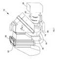
- FIG. 1is a perspective view of a portion of a microturbine engine
- FIG. 2is a schematic illustration of a portion of a power distribution system including the microturbine engine of FIG. 1 ;
- FIG. 3is a chart illustrating a restricted zone
- FIG. 4is a schematic illustration of a portion of a power distribution system including a plurality of microturbine engines.
- a microturbine engine system 10that includes a turbine section 15 , a generator section 20 , and a control system 25 is illustrated.
- the turbine section 15includes a radial flow turbine 35 , a compressor 45 , a recuperator 50 , a combustor 55 , and a gearbox 60 .
- the engine 10includes a Brayton cycle combustion turbine with the recuperator 50 added to improve engine efficiency.
- the engine shownis a single-spool engine (one set of rotating elements). However, multi-spool engines are also contemplated by the invention.
- the compressor 45is a centrifugal-type compressor having a rotary element that rotates in response to operation of the turbine 35 .
- the compressor 45 shownis generally a single-stage compressor. However, multi-stage compressors can be employed where a higher pressure ratio is desired. Alternatively, compressors of different designs (e.g., axial-flow compressors, reciprocating compressors, and the like) can be employed to supply compressed air for use in the engine 10 .
- the turbine 35is a radial flow single-stage turbine having a rotary element directly coupled to the rotary element of the compressor 45 .
- multi-stage turbines or other types of turbinesmay be employed.
- the coupled rotary elements of the turbine 35 and the compressor 45engage the gearbox 60 or other speed reducer disposed between the turbine section 15 and the generator section 20 .
- the coupled rotary elementsdirectly engage the generator section 20 .
- the recuperator 50includes a heat exchanger employed to transfer heat from a hot fluid to the relatively cool compressed air leaving the compressor 45 .
- One suitable recuperator 50is described in U.S. Pat. No. 5,983,992 fully incorporated herein by reference.
- the recuperator 50includes a plurality of heat exchange cells stacked on top of one another to define flow paths therebetween. The cool compressed air flows within the individual cells, while a flow of hot exhaust gas passes between the heat exchange cells.
- the rotary element of the compressor 45rotates in response to rotation of the rotary element of the turbine 35 .
- the compressor 45draws in atmospheric air and increases its pressure.
- the high-pressure airexits the air compressor 45 and flows to the recuperator 50 .
- the flow of compressed air, now preheated within the recuperator 50flows to the combustor as a flow of preheated air.
- the preheated airmixes with a supply of fuel within the combustor 55 and is combusted to produce a flow of products of combustion.
- the use of the recuperator 50 to preheat the airallows for the use of less fuel to reach the desired temperature within the flow of products of combustion, thereby improving engine efficiency.
- the flow of products of combustionenters the turbine 35 and transfers thermal and kinetic energy to the turbine 35 .
- the energy transferresults in rotation of the rotary element of the turbine 35 and a drop in the temperature of the products of combustion.
- the energy transferallows the turbine 35 to drive both the compressor 45 and the generator 20 .
- the products of combustionexit the turbine 35 as a first exhaust gas flow.
- the first turbine 35drives only the compressor, while the second turbine drives the generator 20 or any other device to be driven.
- the second turbinereceives the first exhaust flow, rotates in response to the flow of exhaust gas therethrough, and discharges a second exhaust flow.
- the first exhaust flowenters the flow areas between the heat exchange cells of the recuperator 50 and transfers excess heat energy to the flow of compressed air.
- the exhaust gasthen exits the recuperator 50 and is discharged to the atmosphere, processed, or further used as desired (e.g., cogeneration using a second heat exchanger).
- FIG. 2a portion of the electrical and control systems of a power distribution system 65 is illustrated schematically.
- the microturbine engine 10drives the generator 20 to produce an electrical output.
- the system illustrated hereinincludes a synchronous generator 20 , with other types of generators (e.g., high-speed alternators, asynchronous generators and the like) also functioning with the present invention.
- the generator outputis delivered to a local load bus 70 via a generator output line 75 .
- a generator sensor 80positioned within the generator output line 75 , measures an electrical parameter of the generator 20 during engine operation.
- the generator sensor 80includes a current sensor.
- the measured currentalong with a known voltage, can be used to calculate an actual generator output power.
- Other constructionscan include multiple sensors that measure current, voltage, and/or power directly.
- the generator sensor 80can continuously monitor the electrical parameter or can take periodic measurements as desired.
- the generator output line 75connects to, and delivers power to, the local load bus 70 .
- Various local loads 85e.g., motors, computers, monitors, robots, welding machines, lights, etc. may be powered off the local load bus 70 .
- multiple microturbine engine systems 10are connected to the local load bus 70 , with some or all of them simultaneously providing power to the power distribution system 65 .
- FIG. 4illustrates one possible system that includes multiple engine systems 10 .
- Each engine system 10is electrically connected to the local load bus 70 to allow each engine 10 to provide electrical power.
- Generator sensors 80 a , 80 bare positioned to measure the actual output of each engine system 10 .
- the control system 25is then able to individually control each engine 10 to produce the desired total output.
- the control system 25is able to start or stop individual engines to optimize the system's operation, while providing the desired amount of total power.
- a tie line 90interconnects the local load bus 70 and a utility grid 95 .
- a transformer 100may be disposed within the tie line 90 to step-up or step-down the voltage between the utility grid 95 and the local load bus 70 .
- the tie line 90facilitates the delivery of electricity from the utility grid 95 to the local load bus 70 and/or from the microturbine engine 10 to the utility grid 95 .
- the tie line 90also includes a tie line sensor 105 that measures an electrical parameter (e.g., voltage, current, absolute value of current, power, phase angle, frequency, and the like). In most constructions, the tie line sensor 105 includes a current sensor that measures both the magnitude and direction of current flow within the tie line 90 . However, other constructions may include multiple sensors that measure current, voltage, and/or power flow.
- the tie line sensor 105can continuously monitor the electrical parameter or can take periodic measurements as desired.
- the microturbine engine 10operates intermittently.
- the tie line 90is sized to carry sufficient electricity to power the local loads 85 during periods in which the microturbine engine 10 is inoperative.
- the generator 20synchronized to the utility grid 95 (i.e., the voltage, phase angle, and frequency of the generator output power matched with the utility grid power)
- both the generator 20 and the utility grid 95can provide power to the local load bus 70 and the local loads 85 .
- the microturbine engine 10includes a control system 25 that controls the operation of the engine 10 (or engines in a multiple engine system).
- the control system 25manipulates various components (e.g., valves, pumps, compressors, louvers, switches, relays, and the like) that control various operating parameters of the engine 10 .
- the control system 25may control fuel flow to the engine 10 to control engine speed and/or power output.
- the control system 25may move or initiate movement of a controller that in turn may manipulate a valve, a compressor, or other control member to control the flow of fuel to the combustor 55 , which in turn controls the speed or the power output of the engine 10 .
- the speed of the generator 20is substantially fixed and the control system 25 controls output power.
- a power output set pointis supplied to the control system 25 , which then maintains the generator output at a value substantially equal to the power output set point.
- a manual controlcould be used. The manual control would allow a user to input a desired value between the engine's minimum and maximum output.
- individual power output set points for each engine 10may be used to control the output of each engine 10 .
- a single power output set point that controls the total output of all the enginesmay be used.
- control system 25would determine the specific output levels of each engine 10 using any one of a number of known schemes.
- a preprogrammed curveis used to set the power output set point.
- the curvetypically defines a power output set point that varies with the time of day, day of the week, and/or day of the year.
- other parameterse.g., temperature, pressure, etc.
- Islanding conditionscan arise at any time, but are particularly problematic when the power consumed by the local load 85 is very near the power level output by the generator 20 . Under these “perfectly matched” circumstances, the islanding condition is very difficult to detect using known methods (e.g., rate of change of frequency ROCOF, and the like).
- the present system 65inhibits operation of the engine 10 (or engines) in a particular range or restricted zone 115 .
- the restricted zoneis defined as a power flow within the tie line 90 (into or out of the utility grid 95 ) between zero and a predetermined minimum desired power flow 120 , with the minimum desired power flow 120 being a non-zero value.
- the control system 25receives a signal from the tie line sensor 105 indicating the level of power flow through the tie line 90 . The control system 25 then compares that signal to a predetermined value representing the minimum desired power flow 120 through the tie line 90 .
- the signalmay represent a power flow into the local load bus 70 or a power flow to the utility grid 95 .
- the power output set pointis automatically adjusted. This process continues until the measured power flow through the tie line 90 exceeds the minimum desired power flow 120 . With the measured power flow out of the restricted zone 115 , islanding detection is much easier and is more reliable. As one of ordinary skill will realize, the actual direction of power flow (i.e. into the local load bus or out of the local load bus) does not significantly affect the ability of the present system to detect islanding so long as sufficient power is flowing. As such, the absolute value of the measured power in the tie line 90 is typically all that needs to be measured. In preferred constructions, a minimum power corresponding to a current flow of 500 amps allows for detection of islanding conditions. In still other constructions, a power flow of 100 amps or less allows for the detection of islanding. As one of ordinary skill will realize, the actual minimum desired power flow may vary greatly depending on the system employed.
- the power output set pointis set at 100 kW and the minimum desired power flow is set at 0.5 kW. If the local load 85 is 100 kW, the microturbine engine 10 will supply all of the power to the local load 85 and no power will flow through the tie line 90 . The control system 25 will detect that the flow through the tie line 90 is below the minimum desired power flow 120 and will act to either increase or decrease the power output set point. If the power output set point is reduced (to say 99 kW), power will begin flowing (1 kW) into the local load bus 70 from the utility grid 95 . If on the other hand, the power output set point is increased (to say 101 kW), the microturbine engine output will increase, with the excess power (1 kW) flowing to the utility grid 95 . Under either scenario, the absolute value of the measured power flow through the tie line 90 will eventually exceed the minimum desired power flow 120 .
- the present systemreduces the likelihood of undetected islanding conditions when the engine 10 is driving the generator 20 and producing usable electric power.
- the generator sensor 80monitors the current flow from the generator 20 and provides feed back to the control system 25 .
- the control system 25adjusts the engine 10 to match the output power level to the power output set point.
- the tie line sensor 105monitors the current flow through the tie line 90 and provides an additional feed back loop for the control system 25 .
- the measured power flow at the tie line 90is compared to the minimum desired power flow 120 and the power output set point is reset if the measured power flow falls below the minimum desired power flow 120 .
- the power output set pointcan be increased or decreased as desired to assure that the measured power flow is above the minimum desired power flow 120 .
- the minimum desired power flow 120can be input by the engine user or can be preprogrammed into the control system 25 .
- the actual value usedis a function of many variables (e.g., engine size, instrument sensitivity, instrument accuracy, system load variations, and the like). As such, the values used herein are exemplary and should not be read as limiting in any way.
- microturbine engine 10that drives a synchronous generator 20 .
- generatorse.g., high-speed alternators, asynchronous generators and the like
- systemhas been described as including a single master control system 25 .
- the various control functionscould be divided among multiple controllers or multiple control systems as desired. There is no requirement that a single control system perform all of the control functions described herein.
Landscapes
- Engineering & Computer Science (AREA)
- Power Engineering (AREA)
- Control Of Eletrric Generators (AREA)
- Supply And Distribution Of Alternating Current (AREA)
Abstract
Description
Claims (3)
Priority Applications (1)
| Application Number | Priority Date | Filing Date | Title |
|---|---|---|---|
| US11/563,333US7365444B2 (en) | 2004-03-08 | 2006-11-27 | Active anti-islanding system and method |
Applications Claiming Priority (2)
| Application Number | Priority Date | Filing Date | Title |
|---|---|---|---|
| US10/795,953US7161257B2 (en) | 2004-03-08 | 2004-03-08 | Active anti-islanding system and method |
| US11/563,333US7365444B2 (en) | 2004-03-08 | 2006-11-27 | Active anti-islanding system and method |
Related Parent Applications (1)
| Application Number | Title | Priority Date | Filing Date |
|---|---|---|---|
| US10/795,953ContinuationUS7161257B2 (en) | 2004-03-08 | 2004-03-08 | Active anti-islanding system and method |
Publications (2)
| Publication Number | Publication Date |
|---|---|
| US20070096471A1 US20070096471A1 (en) | 2007-05-03 |
| US7365444B2true US7365444B2 (en) | 2008-04-29 |
Family
ID=34827601
Family Applications (2)
| Application Number | Title | Priority Date | Filing Date |
|---|---|---|---|
| US10/795,953Expired - Fee RelatedUS7161257B2 (en) | 2004-03-08 | 2004-03-08 | Active anti-islanding system and method |
| US11/563,333Expired - LifetimeUS7365444B2 (en) | 2004-03-08 | 2006-11-27 | Active anti-islanding system and method |
Family Applications Before (1)
| Application Number | Title | Priority Date | Filing Date |
|---|---|---|---|
| US10/795,953Expired - Fee RelatedUS7161257B2 (en) | 2004-03-08 | 2004-03-08 | Active anti-islanding system and method |
Country Status (2)
| Country | Link |
|---|---|
| US (2) | US7161257B2 (en) |
| EP (1) | EP1574672B1 (en) |
Cited By (4)
| Publication number | Priority date | Publication date | Assignee | Title |
|---|---|---|---|---|
| US20070097565A1 (en)* | 2005-10-27 | 2007-05-03 | Shinya Oohara | Distributed generation system and power system stabilizing method |
| US20080022920A1 (en)* | 2006-07-10 | 2008-01-31 | Patent-Treuhand-Gesellschaft Fur Elektrische Gluhlampen Mbh | Energy transducer module and light apparatus |
| US20110115301A1 (en)* | 2009-11-13 | 2011-05-19 | Vijay Bhavaraju | Method and area electric power system detecting islanding by employing controlled reactive power injection by a number of inverters |
| US9620994B2 (en) | 2013-01-17 | 2017-04-11 | Eaton Corporation | Method and system of anti-islanding of a microgrid in a grid-connected microgrid system |
Families Citing this family (9)
| Publication number | Priority date | Publication date | Assignee | Title |
|---|---|---|---|---|
| US7161257B2 (en) | 2004-03-08 | 2007-01-09 | Ingersoll-Rand Energy Systems, Inc. | Active anti-islanding system and method |
| ITTO20050711A1 (en)* | 2005-10-07 | 2007-04-08 | Ansaldo Ricerche S P A | RECONFIGURABLE ENERGY DISTRIBUTION NETWORK |
| ITTO20050712A1 (en)* | 2005-10-07 | 2007-04-08 | Ansaldo Ricerche S P A | ELECTRICITY GENERATION SYSTEM |
| US7319307B2 (en)* | 2005-12-16 | 2008-01-15 | General Electric Company | Power balancing of multiple synchronized generators |
| US7457688B2 (en)* | 2006-09-19 | 2008-11-25 | General Electric Company | Method and system for detection and transfer to electrical island operation |
| GB0810512D0 (en) | 2008-06-10 | 2008-07-09 | Rolls Royce Plc | An electrical generator network and a local electrical system |
| BR112012018819A2 (en)* | 2010-01-27 | 2018-06-05 | Dresser Rand Co | advanced topologies of offshore power systems. |
| US8532834B2 (en)* | 2010-10-29 | 2013-09-10 | Hatch Ltd. | Method for integrating controls for captive power generation facilities with controls for metallurgical facilities |
| EP2858201A1 (en)* | 2013-10-07 | 2015-04-08 | ABB Technology AG | Detection of islanding condition in electricity network |
Citations (76)
| Publication number | Priority date | Publication date | Assignee | Title |
|---|---|---|---|---|
| US3491248A (en) | 1967-08-11 | 1970-01-20 | Gulton Ind Inc | Power transmission line switch control system |
| US3499164A (en)* | 1967-05-05 | 1970-03-03 | Caterpillar Tractor Co | Excitation control system for prime mover driven generator |
| US3599007A (en) | 1969-12-29 | 1971-08-10 | Bell Telephone Labor Inc | Digital synchronizer check and synchroscope |
| US3617838A (en) | 1969-01-28 | 1971-11-02 | Bbc Brown Boveri & Cie | Arrangement for stepless speed regulation of a motor fed with current from a converter |
| US3750001A (en) | 1969-11-28 | 1973-07-31 | E Mccloskey | Remote, completely self-contained, self-maintaining power supply apparatus for powering a pressurized-liquid distributing and disseminating system |
| US3781616A (en) | 1971-10-13 | 1973-12-25 | Westinghouse Air Brake Co | Induction motor control system |
| US3794846A (en) | 1972-09-18 | 1974-02-26 | Electric Machinery Mfg Co | Automatic synchronizing control system |
| US3975646A (en) | 1975-01-13 | 1976-08-17 | Westinghouse Electric Corporation | Asynchronous tie |
| US4001666A (en) | 1975-04-03 | 1977-01-04 | General Electric Company | Load peak shaver power regulating system |
| US4031407A (en) | 1970-12-18 | 1977-06-21 | Westinghouse Electric Corporation | System and method employing a digital computer with improved programmed operation for automatically synchronizing a gas turbine or other electric power plant generator with a power system |
| US4039909A (en) | 1975-02-10 | 1977-08-02 | Massachusetts Institute Of Technology | Variable speed electronic motor and the like |
| US4096557A (en) | 1974-05-30 | 1978-06-20 | Schwarz Francisc C | Controllable four quadrant a.c. to a.c. and d.c. converter employing an internal high frequency series resonant link |
| US4132931A (en) | 1976-09-03 | 1979-01-02 | Hitachi, Ltd. | Control system for a.c. motors |
| US4142367A (en) | 1977-10-17 | 1979-03-06 | Eleanor A. Guisti Dondero | Domestic water pressure-flow powered generator system |
| US4227136A (en) | 1978-07-17 | 1980-10-07 | Precise Power Corporation | Variable speed A.C. motor |
| US4249120A (en) | 1979-07-26 | 1981-02-03 | Mcgraw-Edison Co. | Variable speed induction motor control system |
| US4256972A (en) | 1979-05-10 | 1981-03-17 | Beckwith Electric Co., Inc. | Power transfer relay circuitry and method of phase measurement |
| US4276482A (en) | 1977-06-03 | 1981-06-30 | Otis Engineering Corporation | Line flow electric power generator |
| US4277735A (en) | 1978-01-11 | 1981-07-07 | Hitachi, Ltd. | Control apparatus for induction motor |
| US4344025A (en) | 1978-09-04 | 1982-08-10 | Hitachi, Ltd. | Motor control system |
| US4352024A (en) | 1981-05-04 | 1982-09-28 | Carrier Corporation | Expander-generator control system |
| US4392099A (en) | 1979-02-20 | 1983-07-05 | Tokyo Shibaura Denki Kabushiki Kaisha | Starting system for brushless motor |
| US4401938A (en) | 1980-12-29 | 1983-08-30 | Lockheed Corporation | Variable-speed drive for control of induction generators |
| US4417194A (en) | 1980-09-18 | 1983-11-22 | The Charles Stark Draper Laboratory, Inc. | Induction generator system with switched capacitor control |
| US4426611A (en) | 1982-04-28 | 1984-01-17 | General Electric Company | Twelve pulse load commutated inverter drive system |
| US4455522A (en) | 1982-08-02 | 1984-06-19 | General Electric Company | Current source inverter bed induction motor drive |
| US4476424A (en) | 1982-05-03 | 1984-10-09 | The Garrett Corporation | Variable speed induction motor drive system |
| US4517467A (en) | 1982-07-24 | 1985-05-14 | Messerschmidt-Bolkow-Blohm Gmbh | Wind turbine with gale protection |
| US4533835A (en) | 1984-03-15 | 1985-08-06 | Sterling Beckwith | Control apparatus for hydraulically driven generator |
| US4672298A (en) | 1983-05-06 | 1987-06-09 | Frederick Rohatyn | Power factor correction system |
| US4694189A (en) | 1985-09-25 | 1987-09-15 | Hitachi, Ltd. | Control system for variable speed hydraulic turbine generator apparatus |
| US4701691A (en) | 1985-05-14 | 1987-10-20 | Nickoladze Leo G | Synchronous generators |
| US4710692A (en) | 1986-10-16 | 1987-12-01 | Square D Company | Self calibration of the thyristor firing angel of a motor controller using a current window to determine a final value of a reference current lag phase angle |
| US4723104A (en) | 1985-10-02 | 1988-02-02 | Frederick Rohatyn | Energy saving system for larger three phase induction motors |
| US4743777A (en) | 1986-03-07 | 1988-05-10 | Westinghouse Electric Corp. | Starter generator system with two stator exciter windings |
| US4757240A (en) | 1985-10-04 | 1988-07-12 | Hitachi, Ltd. | Apparatus for controlling electric vehicle using induction motor |
| US4791309A (en) | 1982-09-21 | 1988-12-13 | Thamesmead Engineering Limited | Electrical control systems |
| US4794316A (en) | 1986-07-11 | 1988-12-27 | Kabushiki Kaisha Toshiba | Induction machine system |
| US4806781A (en) | 1986-01-17 | 1989-02-21 | Siemens Aktiengesellschaft | Water-driven machine set with the speed reference value set for optimum efficiency |
| US4816696A (en) | 1986-04-30 | 1989-03-28 | Hitachi, Ltd. | Variable-speed pumped-storage power generating system |
| JPH0246135A (en)* | 1988-08-05 | 1990-02-15 | Nippon Telegr & Teleph Corp <Ntt> | Dc feed system |
| US5028804A (en) | 1989-06-30 | 1991-07-02 | The State Of Oregon Acting By And Through The State Board Of Higher Education On Behalf Of Oregon State University | Brushless doubly-fed generator control system |
| US5111377A (en) | 1990-03-02 | 1992-05-05 | Shikoku Research Institute Incorporated | Interconnection for electric power system |
| US5162964A (en) | 1989-08-21 | 1992-11-10 | Nissin Electric Co., Ltd. | Connection control device for controlling the connection of small generator unit to electric power system |
| EP0570976A2 (en) | 1992-05-22 | 1993-11-24 | Mitsubishi Denki Kabushiki Kaisha | Electric power supply system |
| JPH0614465A (en) | 1992-06-24 | 1994-01-21 | Toshiba F Ee Syst Eng Kk | Grid interconnection protection device |
| JPH06141470A (en) | 1992-10-22 | 1994-05-20 | Toshiba F Ee Syst Eng Kk | Protection device for grid-connected inverter |
| JPH06327258A (en) | 1993-05-07 | 1994-11-25 | Toshiba F Ee Syst Eng Kk | Protector for system interconnection |
| EP0677911A1 (en) | 1994-04-12 | 1995-10-18 | Canon Kabushiki Kaisha | Islanding-operation prevention apparatus, and dispersed power generation apparatus and power generation system using the same |
| US5493485A (en) | 1992-06-24 | 1996-02-20 | Kabushiki Kaisha Toshiba | Protection device for stopping operation of an inverter |
| EP0746078A2 (en) | 1995-05-31 | 1996-12-04 | Kabushiki Kaisha Meidensha | Method and apparatus for detecting islanding operation of dispersed generator |
| JPH08331765A (en) | 1995-03-30 | 1996-12-13 | Fuji Electric Co Ltd | Independent operation detection device for grid-connected inverter |
| JPH09247863A (en) | 1996-03-12 | 1997-09-19 | Toshiba Fa Syst Eng Kk | Reactive power compensator for grid interconnection protection |
| EP0810713A2 (en) | 1996-05-29 | 1997-12-03 | Sharp Kabushiki Kaisha | Apparatus and method for detecting an inverter islanding operation |
| JPH10257678A (en) | 1997-03-10 | 1998-09-25 | Kansai Electric Power Co Inc:The | Isolation prevention device for inverter for grid connection |
| WO1999027629A1 (en) | 1997-11-24 | 1999-06-03 | Wills Robert H | Anti-islanding method and apparatus for distributed power generation |
| US5992950A (en) | 1998-03-30 | 1999-11-30 | General Electric Company | Controlled stop function for locomotives |
| US5998880A (en) | 1997-08-07 | 1999-12-07 | General Electric Company | AC locomotive operation without DC current sensor |
| US6107784A (en) | 1996-12-26 | 2000-08-22 | Kabushiki Kaisha Toshiba | System interconnection protective device for non-utility generation equipment |
| US6281595B1 (en) | 2000-09-25 | 2001-08-28 | General Electric Company | Microturbine based power generation system and method |
| US20020047699A1 (en) | 2000-03-23 | 2002-04-25 | Toyokuni Katoh | Interconnection protective device for generator set |
| US20020048179A1 (en) | 2000-09-19 | 2002-04-25 | Shigeo Nomiya | Line linkage protective device for electricity generation equipment |
| US20020060556A1 (en) | 2000-10-12 | 2002-05-23 | Capstone Turbine Corporation | Detection of islanded behavior and anti-islanding protection of a generation in grid-connected mode |
| US6429546B1 (en) | 1998-11-20 | 2002-08-06 | Georgia Tech Research Corporation | Systems and methods for preventing islanding of grid-connected electrical power systems |
| US20020190695A1 (en) | 1997-09-08 | 2002-12-19 | Simon Wall | Turbogenerator with electrical brake |
| US20030007369A1 (en) | 1998-04-02 | 2003-01-09 | Gilbreth Mark G. | Power controller |
| EP1278282A1 (en) | 2001-07-16 | 2003-01-22 | Abb Research Ltd. | Method and apparatus for isolating a first section of an electrical grid from a second section of the electrical grid |
| US20030015873A1 (en) | 2001-01-10 | 2003-01-23 | Claude Khalizadeh | Transient ride-through or load leveling power distribution system |
| US6545885B2 (en) | 2000-03-13 | 2003-04-08 | Nissin Electric Co., Ltd. | Isolated operation prevention device for distributed power supply and interharmonic detection method |
| US20030080741A1 (en) | 2001-10-26 | 2003-05-01 | Lerow Kevin E. | Anti-islanding techniques for distributed power generation |
| US20030098671A1 (en) | 2001-11-26 | 2003-05-29 | Visteon Global Technologies, Inc. | Anti-islanding detection scheme for distributed power generation |
| US20030109977A1 (en)* | 2001-12-06 | 2003-06-12 | Landes James W. | Method and apparatus for parasitic load compensation |
| WO2003106828A2 (en) | 2002-06-18 | 2003-12-24 | Ingersoll-Rand Energy Systems Corporation | Microturbine engine system |
| US6845020B2 (en)* | 2000-11-10 | 2005-01-18 | Ballard Power Systems Corporation | Power converter system |
| US6894403B2 (en) | 2003-02-25 | 2005-05-17 | Honda Motor Co., Ltd. | Engine generator apparatus |
| US7161257B2 (en) | 2004-03-08 | 2007-01-09 | Ingersoll-Rand Energy Systems, Inc. | Active anti-islanding system and method |
Family Cites Families (1)
| Publication number | Priority date | Publication date | Assignee | Title |
|---|---|---|---|---|
| DE69702180T2 (en) | 1996-02-01 | 2001-03-01 | Northern Research & Engineering Corp., Woburn | Plate heat exchanger with fins |
- 2004
- 2004-03-08USUS10/795,953patent/US7161257B2/ennot_activeExpired - Fee Related
- 2005
- 2005-02-08EPEP05250713Apatent/EP1574672B1/ennot_activeExpired - Lifetime
- 2006
- 2006-11-27USUS11/563,333patent/US7365444B2/ennot_activeExpired - Lifetime
Patent Citations (83)
| Publication number | Priority date | Publication date | Assignee | Title |
|---|---|---|---|---|
| US3499164A (en)* | 1967-05-05 | 1970-03-03 | Caterpillar Tractor Co | Excitation control system for prime mover driven generator |
| US3491248A (en) | 1967-08-11 | 1970-01-20 | Gulton Ind Inc | Power transmission line switch control system |
| US3617838A (en) | 1969-01-28 | 1971-11-02 | Bbc Brown Boveri & Cie | Arrangement for stepless speed regulation of a motor fed with current from a converter |
| US3750001A (en) | 1969-11-28 | 1973-07-31 | E Mccloskey | Remote, completely self-contained, self-maintaining power supply apparatus for powering a pressurized-liquid distributing and disseminating system |
| US3599007A (en) | 1969-12-29 | 1971-08-10 | Bell Telephone Labor Inc | Digital synchronizer check and synchroscope |
| US4031407A (en) | 1970-12-18 | 1977-06-21 | Westinghouse Electric Corporation | System and method employing a digital computer with improved programmed operation for automatically synchronizing a gas turbine or other electric power plant generator with a power system |
| US3781616A (en) | 1971-10-13 | 1973-12-25 | Westinghouse Air Brake Co | Induction motor control system |
| US3794846A (en) | 1972-09-18 | 1974-02-26 | Electric Machinery Mfg Co | Automatic synchronizing control system |
| US4096557A (en) | 1974-05-30 | 1978-06-20 | Schwarz Francisc C | Controllable four quadrant a.c. to a.c. and d.c. converter employing an internal high frequency series resonant link |
| US3975646A (en) | 1975-01-13 | 1976-08-17 | Westinghouse Electric Corporation | Asynchronous tie |
| US4039909A (en) | 1975-02-10 | 1977-08-02 | Massachusetts Institute Of Technology | Variable speed electronic motor and the like |
| US4001666A (en) | 1975-04-03 | 1977-01-04 | General Electric Company | Load peak shaver power regulating system |
| US4132931A (en) | 1976-09-03 | 1979-01-02 | Hitachi, Ltd. | Control system for a.c. motors |
| US4276482A (en) | 1977-06-03 | 1981-06-30 | Otis Engineering Corporation | Line flow electric power generator |
| US4142367A (en) | 1977-10-17 | 1979-03-06 | Eleanor A. Guisti Dondero | Domestic water pressure-flow powered generator system |
| US4277735A (en) | 1978-01-11 | 1981-07-07 | Hitachi, Ltd. | Control apparatus for induction motor |
| US4227136A (en) | 1978-07-17 | 1980-10-07 | Precise Power Corporation | Variable speed A.C. motor |
| US4344025A (en) | 1978-09-04 | 1982-08-10 | Hitachi, Ltd. | Motor control system |
| US4392099A (en) | 1979-02-20 | 1983-07-05 | Tokyo Shibaura Denki Kabushiki Kaisha | Starting system for brushless motor |
| US4256972A (en) | 1979-05-10 | 1981-03-17 | Beckwith Electric Co., Inc. | Power transfer relay circuitry and method of phase measurement |
| US4249120A (en) | 1979-07-26 | 1981-02-03 | Mcgraw-Edison Co. | Variable speed induction motor control system |
| US4417194A (en) | 1980-09-18 | 1983-11-22 | The Charles Stark Draper Laboratory, Inc. | Induction generator system with switched capacitor control |
| US4401938A (en) | 1980-12-29 | 1983-08-30 | Lockheed Corporation | Variable-speed drive for control of induction generators |
| US4352024A (en) | 1981-05-04 | 1982-09-28 | Carrier Corporation | Expander-generator control system |
| US4426611A (en) | 1982-04-28 | 1984-01-17 | General Electric Company | Twelve pulse load commutated inverter drive system |
| US4476424A (en) | 1982-05-03 | 1984-10-09 | The Garrett Corporation | Variable speed induction motor drive system |
| US4517467A (en) | 1982-07-24 | 1985-05-14 | Messerschmidt-Bolkow-Blohm Gmbh | Wind turbine with gale protection |
| US4455522A (en) | 1982-08-02 | 1984-06-19 | General Electric Company | Current source inverter bed induction motor drive |
| US4791309A (en) | 1982-09-21 | 1988-12-13 | Thamesmead Engineering Limited | Electrical control systems |
| US4672298A (en) | 1983-05-06 | 1987-06-09 | Frederick Rohatyn | Power factor correction system |
| US4533835A (en) | 1984-03-15 | 1985-08-06 | Sterling Beckwith | Control apparatus for hydraulically driven generator |
| US4701691A (en) | 1985-05-14 | 1987-10-20 | Nickoladze Leo G | Synchronous generators |
| US4694189A (en) | 1985-09-25 | 1987-09-15 | Hitachi, Ltd. | Control system for variable speed hydraulic turbine generator apparatus |
| US4723104A (en) | 1985-10-02 | 1988-02-02 | Frederick Rohatyn | Energy saving system for larger three phase induction motors |
| US4757240A (en) | 1985-10-04 | 1988-07-12 | Hitachi, Ltd. | Apparatus for controlling electric vehicle using induction motor |
| US4806781A (en) | 1986-01-17 | 1989-02-21 | Siemens Aktiengesellschaft | Water-driven machine set with the speed reference value set for optimum efficiency |
| US4743777A (en) | 1986-03-07 | 1988-05-10 | Westinghouse Electric Corp. | Starter generator system with two stator exciter windings |
| US4816696A (en) | 1986-04-30 | 1989-03-28 | Hitachi, Ltd. | Variable-speed pumped-storage power generating system |
| US4794316A (en) | 1986-07-11 | 1988-12-27 | Kabushiki Kaisha Toshiba | Induction machine system |
| US4710692A (en) | 1986-10-16 | 1987-12-01 | Square D Company | Self calibration of the thyristor firing angel of a motor controller using a current window to determine a final value of a reference current lag phase angle |
| JPH0246135A (en)* | 1988-08-05 | 1990-02-15 | Nippon Telegr & Teleph Corp <Ntt> | Dc feed system |
| US5028804A (en) | 1989-06-30 | 1991-07-02 | The State Of Oregon Acting By And Through The State Board Of Higher Education On Behalf Of Oregon State University | Brushless doubly-fed generator control system |
| US5162964A (en) | 1989-08-21 | 1992-11-10 | Nissin Electric Co., Ltd. | Connection control device for controlling the connection of small generator unit to electric power system |
| US5111377A (en) | 1990-03-02 | 1992-05-05 | Shikoku Research Institute Incorporated | Interconnection for electric power system |
| EP0570976A2 (en) | 1992-05-22 | 1993-11-24 | Mitsubishi Denki Kabushiki Kaisha | Electric power supply system |
| US5493485A (en) | 1992-06-24 | 1996-02-20 | Kabushiki Kaisha Toshiba | Protection device for stopping operation of an inverter |
| JPH0614465A (en) | 1992-06-24 | 1994-01-21 | Toshiba F Ee Syst Eng Kk | Grid interconnection protection device |
| JPH06141470A (en) | 1992-10-22 | 1994-05-20 | Toshiba F Ee Syst Eng Kk | Protection device for grid-connected inverter |
| JPH06327258A (en) | 1993-05-07 | 1994-11-25 | Toshiba F Ee Syst Eng Kk | Protector for system interconnection |
| EP0677911A1 (en) | 1994-04-12 | 1995-10-18 | Canon Kabushiki Kaisha | Islanding-operation prevention apparatus, and dispersed power generation apparatus and power generation system using the same |
| US5686766A (en) | 1994-04-12 | 1997-11-11 | Canon Kabushiki Kaisha | Islanding-operation prevention apparatus, and dispersed power generation apparatus and power generation system using the same |
| US5808449A (en) | 1995-02-06 | 1998-09-15 | Kabushiki Kaisha Meidensha | Method and apparatus for detecting islanding operation of dispersed generator |
| JPH08331765A (en) | 1995-03-30 | 1996-12-13 | Fuji Electric Co Ltd | Independent operation detection device for grid-connected inverter |
| EP0746078A2 (en) | 1995-05-31 | 1996-12-04 | Kabushiki Kaisha Meidensha | Method and apparatus for detecting islanding operation of dispersed generator |
| JPH09247863A (en) | 1996-03-12 | 1997-09-19 | Toshiba Fa Syst Eng Kk | Reactive power compensator for grid interconnection protection |
| US6172889B1 (en) | 1996-05-29 | 2001-01-09 | Sharp Kabushiki Kaisha | Inverter apparatus islanding operation detecting method and inverter apparatus capable of surely detecting an islanding operation with a simple construction |
| EP0810713A2 (en) | 1996-05-29 | 1997-12-03 | Sharp Kabushiki Kaisha | Apparatus and method for detecting an inverter islanding operation |
| US6107784A (en) | 1996-12-26 | 2000-08-22 | Kabushiki Kaisha Toshiba | System interconnection protective device for non-utility generation equipment |
| JPH10257678A (en) | 1997-03-10 | 1998-09-25 | Kansai Electric Power Co Inc:The | Isolation prevention device for inverter for grid connection |
| US5998880A (en) | 1997-08-07 | 1999-12-07 | General Electric Company | AC locomotive operation without DC current sensor |
| US20020190695A1 (en) | 1997-09-08 | 2002-12-19 | Simon Wall | Turbogenerator with electrical brake |
| WO1999027629A1 (en) | 1997-11-24 | 1999-06-03 | Wills Robert H | Anti-islanding method and apparatus for distributed power generation |
| US6219623B1 (en) | 1997-11-24 | 2001-04-17 | Plug Power, Inc. | Anti-islanding method and apparatus for distributed power generation |
| US20010056330A1 (en) | 1997-11-24 | 2001-12-27 | Plug Power Inc., Delaware Corporation | Anti-islanding method and apparatus for distributed power generation |
| US5992950A (en) | 1998-03-30 | 1999-11-30 | General Electric Company | Controlled stop function for locomotives |
| US20030007369A1 (en) | 1998-04-02 | 2003-01-09 | Gilbreth Mark G. | Power controller |
| US6429546B1 (en) | 1998-11-20 | 2002-08-06 | Georgia Tech Research Corporation | Systems and methods for preventing islanding of grid-connected electrical power systems |
| US6545885B2 (en) | 2000-03-13 | 2003-04-08 | Nissin Electric Co., Ltd. | Isolated operation prevention device for distributed power supply and interharmonic detection method |
| US20020047699A1 (en) | 2000-03-23 | 2002-04-25 | Toyokuni Katoh | Interconnection protective device for generator set |
| US20020048179A1 (en) | 2000-09-19 | 2002-04-25 | Shigeo Nomiya | Line linkage protective device for electricity generation equipment |
| US6281595B1 (en) | 2000-09-25 | 2001-08-28 | General Electric Company | Microturbine based power generation system and method |
| US20020060556A1 (en) | 2000-10-12 | 2002-05-23 | Capstone Turbine Corporation | Detection of islanded behavior and anti-islanding protection of a generation in grid-connected mode |
| US6845020B2 (en)* | 2000-11-10 | 2005-01-18 | Ballard Power Systems Corporation | Power converter system |
| US20030015873A1 (en) | 2001-01-10 | 2003-01-23 | Claude Khalizadeh | Transient ride-through or load leveling power distribution system |
| EP1278282A1 (en) | 2001-07-16 | 2003-01-22 | Abb Research Ltd. | Method and apparatus for isolating a first section of an electrical grid from a second section of the electrical grid |
| US20030080741A1 (en) | 2001-10-26 | 2003-05-01 | Lerow Kevin E. | Anti-islanding techniques for distributed power generation |
| US20030098671A1 (en) | 2001-11-26 | 2003-05-29 | Visteon Global Technologies, Inc. | Anti-islanding detection scheme for distributed power generation |
| US20030109977A1 (en)* | 2001-12-06 | 2003-06-12 | Landes James W. | Method and apparatus for parasitic load compensation |
| US6920387B2 (en)* | 2001-12-06 | 2005-07-19 | Caterpillar Inc | Method and apparatus for parasitic load compensation |
| WO2003106828A2 (en) | 2002-06-18 | 2003-12-24 | Ingersoll-Rand Energy Systems Corporation | Microturbine engine system |
| US6894403B2 (en) | 2003-02-25 | 2005-05-17 | Honda Motor Co., Ltd. | Engine generator apparatus |
| US7161257B2 (en) | 2004-03-08 | 2007-01-09 | Ingersoll-Rand Energy Systems, Inc. | Active anti-islanding system and method |
| US20070096471A1 (en)* | 2004-03-08 | 2007-05-03 | German Lakov | Active anti-islanding system and method |
Cited By (8)
| Publication number | Priority date | Publication date | Assignee | Title |
|---|---|---|---|---|
| US20070097565A1 (en)* | 2005-10-27 | 2007-05-03 | Shinya Oohara | Distributed generation system and power system stabilizing method |
| US7663348B2 (en)* | 2005-10-27 | 2010-02-16 | Hitachi, Ltd. | Distributed generation system and power system stabilizing method |
| US7948217B2 (en) | 2005-10-27 | 2011-05-24 | Hitachi, Ltd. | Distributed generation system and power system stabilizing method |
| US20080022920A1 (en)* | 2006-07-10 | 2008-01-31 | Patent-Treuhand-Gesellschaft Fur Elektrische Gluhlampen Mbh | Energy transducer module and light apparatus |
| US20110115301A1 (en)* | 2009-11-13 | 2011-05-19 | Vijay Bhavaraju | Method and area electric power system detecting islanding by employing controlled reactive power injection by a number of inverters |
| US8334618B2 (en) | 2009-11-13 | 2012-12-18 | Eaton Corporation | Method and area electric power system detecting islanding by employing controlled reactive power injection by a number of inverters |
| US9502901B2 (en) | 2009-11-13 | 2016-11-22 | Eaton Corporation | Method and area electric power system detecting islanding by employing controlled reactive power injection by a number of inverters |
| US9620994B2 (en) | 2013-01-17 | 2017-04-11 | Eaton Corporation | Method and system of anti-islanding of a microgrid in a grid-connected microgrid system |
Also Published As
| Publication number | Publication date |
|---|---|
| EP1574672A2 (en) | 2005-09-14 |
| EP1574672A3 (en) | 2007-01-24 |
| US7161257B2 (en) | 2007-01-09 |
| US20050194789A1 (en) | 2005-09-08 |
| EP1574672B1 (en) | 2012-08-29 |
| US20070096471A1 (en) | 2007-05-03 |
Similar Documents
| Publication | Publication Date | Title |
|---|---|---|
| US7365444B2 (en) | Active anti-islanding system and method | |
| AU751806B2 (en) | Constant turbine inlet temperature control of a microturbine power generating system | |
| EP1761984B1 (en) | Engine driven power inverter system with cogeneration | |
| CN108350805B (en) | System, method and computer program for operating a land-based or sea-based multi-spool gas turbine | |
| US9605556B2 (en) | Power station and method for its operation | |
| US6198174B1 (en) | Microturbine power generating system | |
| US7122916B2 (en) | Multi-unit power generation system for stand-alone and grid connected operation | |
| RU2344304C2 (en) | System and method of electric power generation | |
| US6170251B1 (en) | Single shaft microturbine power generating system including turbocompressor and auxiliary recuperator | |
| CN102996252B (en) | For operating the method for combined-cycle power plant | |
| US6147414A (en) | Dual-purpose converter/startup circuit for a microturbine power generating system | |
| US20040237535A1 (en) | Method of operating a gas turbine | |
| WO1999032762A1 (en) | An uninterruptible microturbine power generating system | |
| EP3396137B1 (en) | Gas turbine system and method of controlling the same | |
| US6854274B2 (en) | System and method for efficient load following control logic for a turbogenerator operating in stand-alone mode | |
| EP3396117A1 (en) | Gas turbine system and control apparatus and method thereof | |
| JP2019113061A (en) | Systems and methods for dual drive generator | |
| EP2072609A1 (en) | Natural gas liquefaction plant, and power supply system, controller and operating method thereof | |
| EP1059421B1 (en) | Microturbine power generating system | |
| CA2273813C (en) | Microturbine power generating system | |
| AU772937B2 (en) | Microturbine power generating system | |
| IL158305A (en) | Microturbine power generating system | |
| IL130434A (en) | Microturbine power generating system | |
| MXPA06000078A (en) | Electrical power generation system and method |
Legal Events
| Date | Code | Title | Description |
|---|---|---|---|
| AS | Assignment | Owner name:INGERSOLL-RAND ENERGY SYSTEMS, NEW HAMPSHIRE Free format text:ASSIGNMENT OF ASSIGNORS INTEREST;ASSIGNORS:LAKOV, GERMAN;FINSTAD, RANDALL G.;REEL/FRAME:018771/0438 Effective date:20040305 | |
| AS | Assignment | Owner name:SOUTHERN CALIFORNIA GAS COMPANY, CALIFORNIA Free format text:ASSIGNMENT OF ASSIGNORS INTEREST;ASSIGNOR:INGERSOLL-RAND ENERGY SYSTEMS CORPORATION;REEL/FRAME:020279/0715 Effective date:20071220 | |
| STCF | Information on status: patent grant | Free format text:PATENTED CASE | |
| FPAY | Fee payment | Year of fee payment:4 | |
| AS | Assignment | Owner name:FLEXENERGY ENERGY SYSTEMS, INC., CALIFORNIA Free format text:ASSIGNMENT OF ASSIGNORS INTEREST;ASSIGNOR:SOUTHERN CALIFORNIA GAS COMPANY;REEL/FRAME:033132/0476 Effective date:20121001 | |
| FEPP | Fee payment procedure | Free format text:PAT HOLDER CLAIMS SMALL ENTITY STATUS, ENTITY STATUS SET TO SMALL (ORIGINAL EVENT CODE: LTOS); ENTITY STATUS OF PATENT OWNER: SMALL ENTITY | |
| REFU | Refund | Free format text:REFUND - PAYMENT OF MAINTENANCE FEE, 8TH YEAR, LARGE ENTITY (ORIGINAL EVENT CODE: R1552); ENTITY STATUS OF PATENT OWNER: SMALL ENTITY | |
| FPAY | Fee payment | Year of fee payment:8 | |
| FEPP | Fee payment procedure | Free format text:MAINTENANCE FEE REMINDER MAILED (ORIGINAL EVENT CODE: REM.); ENTITY STATUS OF PATENT OWNER: SMALL ENTITY | |
| FEPP | Fee payment procedure | Free format text:11.5 YR SURCHARGE- LATE PMT W/IN 6 MO, SMALL ENTITY (ORIGINAL EVENT CODE: M2556); ENTITY STATUS OF PATENT OWNER: SMALL ENTITY | |
| MAFP | Maintenance fee payment | Free format text:PAYMENT OF MAINTENANCE FEE, 12TH YR, SMALL ENTITY (ORIGINAL EVENT CODE: M2553); ENTITY STATUS OF PATENT OWNER: SMALL ENTITY Year of fee payment:12 | |
| AS | Assignment | Owner name:FLEX LEASING POWER & SERVICE LLC, TEXAS Free format text:ASSIGNMENT OF ASSIGNORS INTEREST;ASSIGNOR:FLEXENERGY ENERGY SYSTEMS, INC.;REEL/FRAME:064634/0761 Effective date:20230805 | |
| AS | Assignment | Owner name:FLEX LEASING POWER & SERVICE LLC, COLORADO Free format text:CHANGE OF ADDRESS;ASSIGNOR:FLEX LEASING POWER & SERVICE LLC;REEL/FRAME:066722/0945 Effective date:20240301 |