US7363090B2 - Band stop filter employing a capacitor and an inductor tank circuit to enhance MRI compatibility of active implantable medical devices - Google Patents
Band stop filter employing a capacitor and an inductor tank circuit to enhance MRI compatibility of active implantable medical devicesDownload PDFInfo
- Publication number
- US7363090B2 US7363090B2US11/743,000US74300007AUS7363090B2US 7363090 B2US7363090 B2US 7363090B2US 74300007 AUS74300007 AUS 74300007AUS 7363090 B2US7363090 B2US 7363090B2
- Authority
- US
- United States
- Prior art keywords
- band stop
- stop filter
- lead wire
- capacitor
- inductor
- Prior art date
- Legal status (The legal status is an assumption and is not a legal conclusion. Google has not performed a legal analysis and makes no representation as to the accuracy of the status listed.)
- Expired - Fee Related
Links
- 239000003990capacitorSubstances0.000titleclaimsabstractdescription106
- WABPQHHGFIMREM-UHFFFAOYSA-Nlead(0)Chemical compound[Pb]WABPQHHGFIMREM-UHFFFAOYSA-N0.000claimsabstractdescription107
- 230000000747cardiac effectEffects0.000claimsdescription36
- 239000007943implantSubstances0.000claimsdescription15
- 210000004556brainAnatomy0.000claimsdescription13
- 239000003814drugSubstances0.000claimsdescription10
- 229940079593drugDrugs0.000claimsdescription8
- 210000000278spinal cordAnatomy0.000claimsdescription8
- 206010007559Cardiac failure congestiveDiseases0.000claimsdescription7
- 206010019280Heart failuresDiseases0.000claimsdescription7
- 230000002861ventricularEffects0.000claimsdescription6
- 230000001225therapeutic effectEffects0.000claimsdescription4
- 206010046543Urinary incontinenceDiseases0.000claimsdescription3
- 230000001410anti-tremorEffects0.000claimsdescription3
- 230000008468bone growthEffects0.000claimsdescription3
- 239000003324growth hormone secretagogueSubstances0.000claimsdescription3
- 239000000523sampleSubstances0.000claimsdescription3
- 210000000988bone and boneAnatomy0.000claimsdescription2
- 230000002526effect on cardiovascular systemEffects0.000claimsdescription2
- 230000004927fusionEffects0.000claimsdescription2
- 230000002496gastric effectEffects0.000claimsdescription2
- 239000002858neurotransmitter agentSubstances0.000claimsdescription2
- 230000000399orthopedic effectEffects0.000claimsdescription2
- 238000002595magnetic resonance imagingMethods0.000description100
- 230000005291magnetic effectEffects0.000description36
- 210000001519tissueAnatomy0.000description32
- 238000010438heat treatmentMethods0.000description21
- 238000013461designMethods0.000description20
- 230000003068static effectEffects0.000description17
- 238000010586diagramMethods0.000description16
- 230000000694effectsEffects0.000description16
- 235000014676Phragmites communisNutrition0.000description15
- 238000000034methodMethods0.000description14
- 230000003071parasitic effectEffects0.000description10
- 210000005241right ventricleAnatomy0.000description9
- 239000000463materialSubstances0.000description8
- RTAQQCXQSZGOHL-UHFFFAOYSA-NTitaniumChemical compound[Ti]RTAQQCXQSZGOHL-UHFFFAOYSA-N0.000description7
- PCHJSUWPFVWCPO-UHFFFAOYSA-NgoldChemical compound[Au]PCHJSUWPFVWCPO-UHFFFAOYSA-N0.000description7
- 229910052737goldInorganic materials0.000description7
- 239000010931goldSubstances0.000description7
- 239000010936titaniumSubstances0.000description7
- 229910052719titaniumInorganic materials0.000description7
- 238000002679ablationMethods0.000description6
- 239000000919ceramicSubstances0.000description6
- 238000003066decision treeMethods0.000description6
- NOESYZHRGYRDHS-UHFFFAOYSA-NinsulinChemical compoundN1C(=O)C(NC(=O)C(CCC(N)=O)NC(=O)C(CCC(O)=O)NC(=O)C(C(C)C)NC(=O)C(NC(=O)CN)C(C)CC)CSSCC(C(NC(CO)C(=O)NC(CC(C)C)C(=O)NC(CC=2C=CC(O)=CC=2)C(=O)NC(CCC(N)=O)C(=O)NC(CC(C)C)C(=O)NC(CCC(O)=O)C(=O)NC(CC(N)=O)C(=O)NC(CC=2C=CC(O)=CC=2)C(=O)NC(CSSCC(NC(=O)C(C(C)C)NC(=O)C(CC(C)C)NC(=O)C(CC=2C=CC(O)=CC=2)NC(=O)C(CC(C)C)NC(=O)C(C)NC(=O)C(CCC(O)=O)NC(=O)C(C(C)C)NC(=O)C(CC(C)C)NC(=O)C(CC=2NC=NC=2)NC(=O)C(CO)NC(=O)CNC2=O)C(=O)NCC(=O)NC(CCC(O)=O)C(=O)NC(CCCNC(N)=N)C(=O)NCC(=O)NC(CC=3C=CC=CC=3)C(=O)NC(CC=3C=CC=CC=3)C(=O)NC(CC=3C=CC(O)=CC=3)C(=O)NC(C(C)O)C(=O)N3C(CCC3)C(=O)NC(CCCCN)C(=O)NC(C)C(O)=O)C(=O)NC(CC(N)=O)C(O)=O)=O)NC(=O)C(C(C)CC)NC(=O)C(CO)NC(=O)C(C(C)O)NC(=O)C1CSSCC2NC(=O)C(CC(C)C)NC(=O)C(NC(=O)C(CCC(N)=O)NC(=O)C(CC(N)=O)NC(=O)C(NC(=O)C(N)CC=1C=CC=CC=1)C(C)C)CC1=CN=CN1NOESYZHRGYRDHS-UHFFFAOYSA-N0.000description6
- 230000004044responseEffects0.000description6
- 230000001413cellular effectEffects0.000description5
- 230000006870functionEffects0.000description5
- 238000003384imaging methodMethods0.000description5
- 230000001939inductive effectEffects0.000description5
- 239000012212insulatorSubstances0.000description5
- 239000008280bloodSubstances0.000description4
- 210000004369bloodAnatomy0.000description4
- 230000006378damageEffects0.000description4
- 230000002107myocardial effectEffects0.000description4
- BASFCYQUMIYNBI-UHFFFAOYSA-NplatinumChemical compound[Pt]BASFCYQUMIYNBI-UHFFFAOYSA-N0.000description4
- 230000008569processEffects0.000description4
- 210000005245right atriumAnatomy0.000description4
- 230000035939shockEffects0.000description4
- 238000002560therapeutic procedureMethods0.000description4
- 229910000859α-FeInorganic materials0.000description4
- PNEYBMLMFCGWSK-UHFFFAOYSA-NAluminaChemical compound[O-2].[O-2].[O-2].[Al+3].[Al+3]PNEYBMLMFCGWSK-UHFFFAOYSA-N0.000description3
- 102000004877InsulinHuman genes0.000description3
- 108090001061InsulinProteins0.000description3
- 238000013459approachMethods0.000description3
- 230000002238attenuated effectEffects0.000description3
- 230000008901benefitEffects0.000description3
- 238000004364calculation methodMethods0.000description3
- 238000009125cardiac resynchronization therapyMethods0.000description3
- 230000008859changeEffects0.000description3
- 230000008878couplingEffects0.000description3
- 238000010168coupling processMethods0.000description3
- 238000005859coupling reactionMethods0.000description3
- 238000002405diagnostic procedureMethods0.000description3
- 239000003989dielectric materialSubstances0.000description3
- 238000006073displacement reactionMethods0.000description3
- 230000005672electromagnetic fieldEffects0.000description3
- 238000005516engineering processMethods0.000description3
- 229940125396insulinDrugs0.000description3
- 210000005240left ventricleAnatomy0.000description3
- 238000005259measurementMethods0.000description3
- 230000008672reprogrammingEffects0.000description3
- 230000000638stimulationEffects0.000description3
- 238000012360testing methodMethods0.000description3
- 239000013598vectorSubstances0.000description3
- 206010010904ConvulsionDiseases0.000description2
- 230000005355Hall effectEffects0.000description2
- BQCADISMDOOEFD-UHFFFAOYSA-NSilverChemical compound[Ag]BQCADISMDOOEFD-UHFFFAOYSA-N0.000description2
- 206010047281Ventricular arrhythmiaDiseases0.000description2
- 230000003187abdominal effectEffects0.000description2
- 238000010521absorption reactionMethods0.000description2
- 230000004075alterationEffects0.000description2
- 206010003119arrhythmiaDiseases0.000description2
- 230000006793arrhythmiaEffects0.000description2
- 230000000712assemblyEffects0.000description2
- 238000000429assemblyMethods0.000description2
- 210000001124body fluidAnatomy0.000description2
- 239000010839body fluidSubstances0.000description2
- 210000000038chestAnatomy0.000description2
- 239000004020conductorSubstances0.000description2
- 230000009977dual effectEffects0.000description2
- 239000007772electrode materialSubstances0.000description2
- 238000011156evaluationMethods0.000description2
- 239000011521glassSubstances0.000description2
- 238000003780insertionMethods0.000description2
- 230000037431insertionEffects0.000description2
- 230000000670limiting effectEffects0.000description2
- 239000000696magnetic materialSubstances0.000description2
- 230000007246mechanismEffects0.000description2
- 238000012544monitoring processMethods0.000description2
- 238000013021overheatingMethods0.000description2
- 229910052697platinumInorganic materials0.000description2
- 238000011160researchMethods0.000description2
- 230000033764rhythmic processEffects0.000description2
- 229910052709silverInorganic materials0.000description2
- 239000004332silverSubstances0.000description2
- 229920001187thermosetting polymerPolymers0.000description2
- 208000003663ventricular fibrillationDiseases0.000description2
- TVEXGJYMHHTVKP-UHFFFAOYSA-N6-oxabicyclo[3.2.1]oct-3-en-7-oneChemical compoundC1C2C(=O)OC1C=CC2TVEXGJYMHHTVKP-UHFFFAOYSA-N0.000description1
- 208000033988Device pacing issueDiseases0.000description1
- 239000004593EpoxySubstances0.000description1
- CWYNVVGOOAEACU-UHFFFAOYSA-NFe2+Chemical compound[Fe+2]CWYNVVGOOAEACU-UHFFFAOYSA-N0.000description1
- 238000006842Henry reactionMethods0.000description1
- 206010021639IncontinenceDiseases0.000description1
- XEEYBQQBJWHFJM-UHFFFAOYSA-NIronChemical group[Fe]XEEYBQQBJWHFJM-UHFFFAOYSA-N0.000description1
- 206010028980NeoplasmDiseases0.000description1
- 208000008589ObesityDiseases0.000description1
- 239000004642PolyimideSubstances0.000description1
- UELITFHSCLAHKR-UHFFFAOYSA-Nacibenzolar-S-methylChemical compoundCSC(=O)C1=CC=CC2=C1SN=N2UELITFHSCLAHKR-UHFFFAOYSA-N0.000description1
- 230000009471actionEffects0.000description1
- 239000000853adhesiveSubstances0.000description1
- 230000001070adhesive effectEffects0.000description1
- 230000002411adverseEffects0.000description1
- 210000003484anatomyAnatomy0.000description1
- 239000000560biocompatible materialSubstances0.000description1
- 230000005540biological transmissionEffects0.000description1
- 210000005013brain tissueAnatomy0.000description1
- 210000005242cardiac chamberAnatomy0.000description1
- 206010061592cardiac fibrillationDiseases0.000description1
- 238000013194cardioversionMethods0.000description1
- 230000015556catabolic processEffects0.000description1
- 229940044683chemotherapy drugDrugs0.000description1
- 210000003477cochleaAnatomy0.000description1
- 210000000860cochlear nerveAnatomy0.000description1
- 238000004891communicationMethods0.000description1
- 238000013016dampingMethods0.000description1
- 238000006731degradation reactionMethods0.000description1
- 230000001419dependent effectEffects0.000description1
- 238000012938design processMethods0.000description1
- 230000001066destructive effectEffects0.000description1
- 238000001514detection methodMethods0.000description1
- 230000001627detrimental effectEffects0.000description1
- 238000011161developmentMethods0.000description1
- 230000018109developmental processEffects0.000description1
- 230000005684electric fieldEffects0.000description1
- 238000002001electrophysiologyMethods0.000description1
- 230000007831electrophysiologyEffects0.000description1
- 230000008030eliminationEffects0.000description1
- 238000003379elimination reactionMethods0.000description1
- 238000004146energy storageMethods0.000description1
- 206010015037epilepsyDiseases0.000description1
- 125000003700epoxy groupChemical group0.000description1
- 230000005294ferromagnetic effectEffects0.000description1
- 230000002600fibrillogenic effectEffects0.000description1
- 238000010304firingMethods0.000description1
- 231100001261hazardousToxicity0.000description1
- 210000003128headAnatomy0.000description1
- 230000035876healingEffects0.000description1
- 230000036039immunityEffects0.000description1
- 238000001453impedance spectrumMethods0.000description1
- 238000010348incorporationMethods0.000description1
- 238000013152interventional procedureMethods0.000description1
- 210000000867larynxAnatomy0.000description1
- 230000004807localizationEffects0.000description1
- 230000007774longtermEffects0.000description1
- 208000020816lung neoplasmDiseases0.000description1
- 238000012986modificationMethods0.000description1
- 230000004048modificationEffects0.000description1
- 208000031225myocardial ischemiaDiseases0.000description1
- 210000000944nerve tissueAnatomy0.000description1
- 238000001208nuclear magnetic resonance pulse sequenceMethods0.000description1
- 235000020824obesityNutrition0.000description1
- 210000000056organAnatomy0.000description1
- 230000000661pacemaking effectEffects0.000description1
- 238000004806packaging method and processMethods0.000description1
- 229940124583pain medicationDrugs0.000description1
- 230000000149penetrating effectEffects0.000description1
- 230000035515penetrationEffects0.000description1
- 230000035479physiological effects, processes and functionsEffects0.000description1
- 229920000647polyepoxidePolymers0.000description1
- 229920001721polyimidePolymers0.000description1
- 239000000843powderSubstances0.000description1
- 238000000718qrs complexMethods0.000description1
- 238000007674radiofrequency ablationMethods0.000description1
- 230000009467reductionEffects0.000description1
- 230000002829reductive effectEffects0.000description1
- 238000012552reviewMethods0.000description1
- 238000010615ring circuitMethods0.000description1
- 231100000241scarToxicity0.000description1
- 238000007789sealingMethods0.000description1
- 230000035945sensitivityEffects0.000description1
- 238000002633shock therapyMethods0.000description1
- 229910000679solderInorganic materials0.000description1
- 229910001220stainless steelInorganic materials0.000description1
- 239000010935stainless steelSubstances0.000description1
- 238000001356surgical procedureMethods0.000description1
- 230000001360synchronised effectEffects0.000description1
- 230000000451tissue damageEffects0.000description1
- 231100000827tissue damageToxicity0.000description1
- 238000011282treatmentMethods0.000description1
- 230000005641tunnelingEffects0.000description1
- 210000001186vagus nerveAnatomy0.000description1
- 230000002792vascularEffects0.000description1
Images


Classifications
- A—HUMAN NECESSITIES
- A61—MEDICAL OR VETERINARY SCIENCE; HYGIENE
- A61B—DIAGNOSIS; SURGERY; IDENTIFICATION
- A61B18/00—Surgical instruments, devices or methods for transferring non-mechanical forms of energy to or from the body
- A61B18/04—Surgical instruments, devices or methods for transferring non-mechanical forms of energy to or from the body by heating
- A61B18/12—Surgical instruments, devices or methods for transferring non-mechanical forms of energy to or from the body by heating by passing a current through the tissue to be heated, e.g. high-frequency current
- A61B18/14—Probes or electrodes therefor
- A61B18/1492—Probes or electrodes therefor having a flexible, catheter-like structure, e.g. for heart ablation
- A—HUMAN NECESSITIES
- A61—MEDICAL OR VETERINARY SCIENCE; HYGIENE
- A61N—ELECTROTHERAPY; MAGNETOTHERAPY; RADIATION THERAPY; ULTRASOUND THERAPY
- A61N1/00—Electrotherapy; Circuits therefor
- A61N1/02—Details
- A61N1/04—Electrodes
- A61N1/05—Electrodes for implantation or insertion into the body, e.g. heart electrode
- A—HUMAN NECESSITIES
- A61—MEDICAL OR VETERINARY SCIENCE; HYGIENE
- A61N—ELECTROTHERAPY; MAGNETOTHERAPY; RADIATION THERAPY; ULTRASOUND THERAPY
- A61N1/00—Electrotherapy; Circuits therefor
- A61N1/18—Applying electric currents by contact electrodes
- A61N1/32—Applying electric currents by contact electrodes alternating or intermittent currents
- A61N1/36—Applying electric currents by contact electrodes alternating or intermittent currents for stimulation
- A61N1/362—Heart stimulators
- A61N1/37—Monitoring; Protecting
- G—PHYSICS
- G01—MEASURING; TESTING
- G01R—MEASURING ELECTRIC VARIABLES; MEASURING MAGNETIC VARIABLES
- G01R33/00—Arrangements or instruments for measuring magnetic variables
- G01R33/20—Arrangements or instruments for measuring magnetic variables involving magnetic resonance
- G01R33/28—Details of apparatus provided for in groups G01R33/44 - G01R33/64
- G01R33/285—Invasive instruments, e.g. catheters or biopsy needles, specially adapted for tracking, guiding or visualization by NMR
- G01R33/287—Invasive instruments, e.g. catheters or biopsy needles, specially adapted for tracking, guiding or visualization by NMR involving active visualization of interventional instruments, e.g. using active tracking RF coils or coils for intentionally creating magnetic field inhomogeneities
- H—ELECTRICITY
- H03—ELECTRONIC CIRCUITRY
- H03H—IMPEDANCE NETWORKS, e.g. RESONANT CIRCUITS; RESONATORS
- H03H1/00—Constructional details of impedance networks whose electrical mode of operation is not specified or applicable to more than one type of network
- H03H1/0007—Constructional details of impedance networks whose electrical mode of operation is not specified or applicable to more than one type of network of radio frequency interference filters
- A—HUMAN NECESSITIES
- A61—MEDICAL OR VETERINARY SCIENCE; HYGIENE
- A61B—DIAGNOSIS; SURGERY; IDENTIFICATION
- A61B18/00—Surgical instruments, devices or methods for transferring non-mechanical forms of energy to or from the body
- A61B2018/00636—Sensing and controlling the application of energy
- A61B2018/00773—Sensed parameters
- A61B2018/00839—Bioelectrical parameters, e.g. ECG, EEG
- A—HUMAN NECESSITIES
- A61—MEDICAL OR VETERINARY SCIENCE; HYGIENE
- A61B—DIAGNOSIS; SURGERY; IDENTIFICATION
- A61B90/00—Instruments, implements or accessories specially adapted for surgery or diagnosis and not covered by any of the groups A61B1/00 - A61B50/00, e.g. for luxation treatment or for protecting wound edges
- A61B90/36—Image-producing devices or illumination devices not otherwise provided for
- A61B90/37—Surgical systems with images on a monitor during operation
- A61B2090/374—NMR or MRI
- A—HUMAN NECESSITIES
- A61—MEDICAL OR VETERINARY SCIENCE; HYGIENE
- A61N—ELECTROTHERAPY; MAGNETOTHERAPY; RADIATION THERAPY; ULTRASOUND THERAPY
- A61N1/00—Electrotherapy; Circuits therefor
- A61N1/02—Details
- A61N1/08—Arrangements or circuits for monitoring, protecting, controlling or indicating
- A61N1/086—Magnetic resonance imaging [MRI] compatible leads
- A—HUMAN NECESSITIES
- A61—MEDICAL OR VETERINARY SCIENCE; HYGIENE
- A61N—ELECTROTHERAPY; MAGNETOTHERAPY; RADIATION THERAPY; ULTRASOUND THERAPY
- A61N1/00—Electrotherapy; Circuits therefor
- A61N1/18—Applying electric currents by contact electrodes
- A61N1/32—Applying electric currents by contact electrodes alternating or intermittent currents
- A61N1/36—Applying electric currents by contact electrodes alternating or intermittent currents for stimulation
- A61N1/362—Heart stimulators
- A61N1/37—Monitoring; Protecting
- A61N1/3718—Monitoring of or protection against external electromagnetic fields or currents
- G—PHYSICS
- G01—MEASURING; TESTING
- G01R—MEASURING ELECTRIC VARIABLES; MEASURING MAGNETIC VARIABLES
- G01R33/00—Arrangements or instruments for measuring magnetic variables
- G01R33/20—Arrangements or instruments for measuring magnetic variables involving magnetic resonance
- G01R33/28—Details of apparatus provided for in groups G01R33/44 - G01R33/64
- G01R33/288—Provisions within MR facilities for enhancing safety during MR, e.g. reduction of the specific absorption rate [SAR], detection of ferromagnetic objects in the scanner room
- H—ELECTRICITY
- H03—ELECTRONIC CIRCUITRY
- H03H—IMPEDANCE NETWORKS, e.g. RESONANT CIRCUITS; RESONATORS
- H03H7/00—Multiple-port networks comprising only passive electrical elements as network components
- H03H7/01—Frequency selective two-port networks
- H03H2007/013—Notch or bandstop filters
- H—ELECTRICITY
- H03—ELECTRONIC CIRCUITRY
- H03H—IMPEDANCE NETWORKS, e.g. RESONANT CIRCUITS; RESONATORS
- H03H7/00—Multiple-port networks comprising only passive electrical elements as network components
- H03H7/01—Frequency selective two-port networks
- H03H7/17—Structural details of sub-circuits of frequency selective networks
- H03H7/1741—Comprising typical LC combinations, irrespective of presence and location of additional resistors
- H03H7/1766—Parallel LC in series path
- Y—GENERAL TAGGING OF NEW TECHNOLOGICAL DEVELOPMENTS; GENERAL TAGGING OF CROSS-SECTIONAL TECHNOLOGIES SPANNING OVER SEVERAL SECTIONS OF THE IPC; TECHNICAL SUBJECTS COVERED BY FORMER USPC CROSS-REFERENCE ART COLLECTIONS [XRACs] AND DIGESTS
- Y10—TECHNICAL SUBJECTS COVERED BY FORMER USPC
- Y10T—TECHNICAL SUBJECTS COVERED BY FORMER US CLASSIFICATION
- Y10T29/00—Metal working
- Y10T29/49—Method of mechanical manufacture
- Y10T29/49002—Electrical device making
- Y10T29/49117—Conductor or circuit manufacturing
- Y10T29/49169—Assembling electrical component directly to terminal or elongated conductor
Definitions
- This inventionrelates generally to novel EMI tank filter assemblies, particularly of the type used in active implantable medical devices (AIMDs) such as cardiac pacemakers, cardioverter defibrillators, neurostimulators, and the like, which decouple implantable lead wires and/or electronic components of the implantable medical device from undesirable electromagnetic interference (EMI) signals at a selected frequency or frequencies, such as the RF pulsed fields of Magnetic Resonance Imaging (MRI) equipment.
- AIMDsactive implantable medical devices
- EMIelectromagnetic interference
- MRIis indeed often used with pacemaker, neurostimulator and other active implantable medical device (AIMD) patients.
- AIMDactive implantable medical device
- the safety and feasibility of MRI in patients with cardiac pacemakersis an issue of gaining significance.
- the effects of MRI on patients' pacemaker systemshave only been analyzed retrospectively in some case reports.
- T0.5 Tesla
- MRIis one of medicine's most valuable diagnostic tools.
- MRIis, of course, extensively used for imaging, but is also used for interventional medicine (surgery).
- MRIis used in real time to guide ablation catheters, neurostimulator tips, deep brain probes and the like.
- An absolute contra-indication for pacemaker patientsmeans that pacemaker and ICD wearers are excluded from MRI. This is particularly true of scans of the thorax and abdominal areas. Because of MRI's enormous value as a diagnostic tool for imaging organs and other body tissues, many physicians simply take the risk and go ahead and perform MRI on a pacemaker patient. The literature indicates a number of precautions that physicians should take in this case, including limiting the power of the MRI RF Pulsed field (Specific Absorption Rate—SAR level), programming the pacemaker to fixed or asynchronous pacing mode, and then careful reprogramming and evaluation of the pacemaker and patient after the procedure is complete. There have been reports of latent problems with cardiac pacemakers or other AIMDs after an MRI procedure sometimes occurring many days later.
- SAR levelSpecific Absorption Rate—SAR level
- the first typeis the main static magnetic field designated B 0 which is used to align protons in body tissue.
- B 0main static magnetic field
- the field strengthvaries from 0.5 to 3.0 Tesla in most of the currently available MRI units in clinical use. Some of the newer MRI system fields can go as high as 4 to 5 Tesla.
- ISMRMInternational Society for Magnetic Resonance in Medicine
- a static magnetic fieldcan induce powerful mechanical forces and torque on any magnetic materials implanted within the patient. This would include certain components within the cardiac pacemaker itself and or lead wire systems.
- the second type of field produced by magnetic resonance imagingis the pulsed RF field which is generated by the body coil or head coil. This is used to change the energy state of the protons and illicit MRI signals from tissue.
- the RF fieldis homogeneous in the central region and has two main components: (1) the magnetic field is circularly polarized in the actual plane; and (2) the electric field is related to the magnetic field by Maxwell's equations.
- the RF fieldis switched on and off during measurements and usually has a frequency of 21 MHz to 64 MHz to 128 MHz depending upon the static magnetic field strength.
- the third type of electromagnetic fieldis the time-varying magnetic gradient fields designated B 1 which are used for spatial localization. These change their strength along different orientations and operating frequencies on the order of 1 kHz.
- the vectors of the magnetic field gradients in the X, Y and Z directionsare produced by three sets of orthogonally positioned coils and are switched on only during the measurements. In some cases, the gradient field has been shown to elevate natural heart rhythms (heart beat). This is not completely understood, but it is a repeatable phenomenon. The gradient field is not considered by many researchers to create any other adverse effects.
- VLFvery low frequency
- EMIEMI signals are induced only into the first area of the lead wire system (for example, at the header block of a cardiac pacemaker). This has to do with the wavelength of the signals involved and where they couple efficiently into the system.
- Magnetic field coupling into an implanted lead wire systemis based on loop areas.
- a cardiac pacemakerthere is a loop formed by the lead wire as it comes from the cardiac pacemaker housing to its distal TIP, for example, located in the right ventricle.
- the return pathis through body fluid and tissue generally straight from the TIP electrode in the right ventricle back up to the pacemaker case or housing.
- This forms an enclosed areawhich can be measured from patient X-rays in square centimeters.
- the average loop areais 200 to 225 square centimeters. This is an average and is subject to great statistical variation. For example, in a large adult patient with an abdominal implant, the implanted loop area is much larger (greater than 450 square centimeters).
- the magnetic gradient fieldswould be induced through enclosed loop areas.
- the pulsed RF fieldswhich are generated by the body coil, would be primarily induced into the lead wire system by antenna action.
- ICDsimplantable cardioverter defibrillators
- ICDsuse different and larger batteries which could cause higher magnetic forces.
- the programmable sensitivity in ICDsis normally much higher (more sensitive) than it is for pacemakers, therefore, ICDs may falsely detect a ventricular tacchyarrhythmia and inappropriately deliver therapy.
- therapymight include anti-tacchycardia pacing, cardio version or defibrillation (high voltage shock) therapies.
- MRI magnetic fieldsmay prevent detection of a dangerous ventricular arrhythmia or fibrillation.
- There can also be heating problems of ICD leadswhich are expected to be comparable to those of pacemaker leads. Ablation of vascular walls is another concern.
- ICDshave a sort of built-in fail-safe mechanism. That is, during an MRI procedure, if they inadvertently sense the MRI fields as a dangerous ventricular arrhythmia, the ICD will attempt to charge up and deliver a high voltage shock.
- a transformer contained within the ICDthat is necessary to function in order to charge up the high-energy storage capacitor contained within the ICD. In the presence of the main static field of the MRI the core of this transformer tends to saturate thereby preventing the high voltage capacitor from charging up. This makes it highly unlikely that an ICD patient undergoing an MRI would receive an inappropriate high voltage shock therapy.
- ICDscannot charge during MRI due to the saturation of their ferro-magnetic transformers, the battery will be effectively shorted and lose life. This is a highly undesirable condition.
- the relatively short antenna on the cell phoneis designed to efficiently couple with the very high frequency wavelengths (approximately 950 MHz) of cellular telephone signals. In a typical AM and FM radio in an automobile, these wavelength signals would not efficiently couple to the relatively short antenna of a cell phone. This is why the antenna on the automobile is relatively longer.
- Insulin drug pump systemsdo not seem to be of a major current concern due to the fact that they have no significant antenna components (such as implanted lead wires).
- some implantable pumpswork on magneto-peristaltic systems, and must be deactivated prior to MRI.
- a novel resonant tank or band stop filter assemblywhich can be placed at various locations along the active implantable medical device lead wire system, which also prevents current from circulating at selected frequencies of the medical therapeutic device.
- such novel tank filterswould be designed to resonate at 64 MHz for use in an MRI system operating at 1.5 Tesla (or 128 MHz for a 3 Tesla system).
- the present inventionfulfills these needs and provides other related advantages.
- the present inventioncomprises resonant tank circuits/band stop filters to be placed at one or more locations along the active implantable medical device (AIMD) lead wire system, including its distal Tip.
- These band stop filtersprevent current from circulating at selected frequencies of the medical therapeutic device.
- the pulse RF frequencyis 64 MHz.
- the novel band stop filters of the present inventioncan be designed to resonate at 64 MHz and thus create an open circuit in the implanted lead wire system at that selected frequency.
- the band stop filter of the present inventionwhen placed at the distal TIP, will prevent currents from flowing through the distal TIP, prevent currents from flowing in the implanted lead wires and also prevent currents from flowing into body tissue.
- a capacitor in parallel with an inductoris known as a tank filter. It is also well known that when the tank filter is at its resonant frequency, it will present a very high impedance. This is a basic principle of all radio receivers. In fact, multiple tank filters are often used to improve the selectivity of a radio receiver. One can adjust the resonant frequency of the tank circuit by either adjusting the capacitor value or the inductor value or both. Since medical diagnostic equipment which is capable of producing very large fields operates at discrete frequencies, this is an ideal situation for a specific tank or band stop filter. Band stop filters are more efficient for eliminating one single frequency than broadband filters.
- the band stop filteris targeted at this one frequency or range of frequencies, it can be much smaller and volumetrically efficient suitable for incorporation into an implantable medical device.
- various loops and associated loop currentsresult along various sections of the implanted lead wire.
- EMFelectromagnetic forces
- This current systemis largely decoupled from the currents that are induced near the active implantable medical device, for example, near the cardiac pacemaker.
- the MRImay set up a separate loop with its associated currents. Accordingly, one or more band stop filters may be required to completely control all of the various induced EMI and associated currents in a lead wire system.
- the present inventionwhich resides in band stop filters is also designed to work in concert with the EMI filter which is typically used at the point of lead wire ingress and egress of the active implantable medical device.
- the EMI filterwhich is typically used at the point of lead wire ingress and egress of the active implantable medical device.
- U.S. Pat. No. 6,999,818, entitled INDUCTOR CAPACITOR EMI FILTER FOR HUMAN IMPLANT APPLICATIONSU.S. patent application Ser. No. 11/097,999 filed Mar.
- the inventionprovides a medical therapeutic device comprising an active implantable medical device (AIMD), an implantable lead wire extending from the AIMD to a distal TIP thereof, and a band stop filter associated with the implantable lead wire for attenuating current flow through the lead wire at a selected frequency.
- AIMDactive implantable medical device
- a band stop filterassociated with the implantable lead wire for attenuating current flow through the lead wire at a selected frequency.
- the AIMDmay comprise cochlear implants, piezoelectric sound bridge transducers, neurostimulators, brain stimulators, cardiac pacemakers, ventricular assist devices, artificial hearts, drug pumps, bone growth stimulators, bone fusion stimulators, urinary incontinence devices, pain relief spinal cord stimulators, anti-tremor stimulators, gastric stimulators, implantable cardioverter defibrillators, pH probes, congestive heart failure devices, neuromodulators, cardiovascular stents, orthopedic implants, and the like.
- the band stop filteritself comprises a capacitor (and its resistance or an added resistance) in parallel with an inductor (and its parasitic resistance), said parallel capacitor and inductor combination being placed in series with the medical device implantable lead wire(s) wherein the values of capacitance and inductance have been selected such that the band stop filter is resonant at a selected frequency (such as the MRI pulsed frequency).
- the overall Q factor of the band stop filteris selected to balance impedance at the selected frequency versus frequency band width characteristics. More specifically, the Q of the inductor is relatively maximized and the Q of the capacitor is relatively minimized to reduce the overall Q of the band stop filter.
- the Q of the inductoris relatively maximized by minimizing the parasitic resistive loss in the inductor, and the Q of the capacitor is relatively minimized by raising its equivalent series resistance (ESR) of the capacitor (or by adding resistance or a resistive element in series with the capacitor element of the bank stop tank filter). This reduces the overall Q of the band stop filter in order to broaden its 3 dB points and thereby attenuate current flow through the lead wire along a range of selected frequencies.
- the range of selected frequenciesincludes a plurality of MRI pulsed frequencies.
- the equivalent series resistance of the capacitoris raised by any of the following: reducing thickness of electrode plates in the capacitor; using higher resistivity capacitor electrode materials, providing apertures, gaps, slits or spokes in the electrode plates of the capacitor; providing separate discrete resistors in series with the capacitor; utilizing resistive electrical attachment materials to the capacitor; or utilizing capacitor dielectric materials that have high dielectric loss tangents at the selected frequency.
- Methods of using higher resistivity capacitor electrode materialsinclude, for example, using platinum instead of silver electrodes. Platinum has a higher volume resistivity as compared to pure silver.
- Another way of reducing capacitor electrode plate resistivityis to add ceramic powders to the electrode ink before it is silk screened down and fired. After firing, this has the effect of separating the conductive electrode portions by insulative dielectric areas which increases the overall resistivity of the electrode plate.
- raising the capacitor ESRincludes any or all of the above described methods of adding resistance in series with the capacitive element of the band stop filter. It should be noted that deliberately raising the capacitor ESR runs counter to conventional/prior art capacitor technologies. In fact, capacitor manufacturers generally strive to build capacitors with as low an ESR as possible. This is to minimize energy loss, etc. It is a feature of the present invention that capacitor Q is raised in a controlled manner in the tank filter circuit in order to adjust its Q and adjust the band stop frequency width in the range of MRI pulsed frequencies.
- the band stop filteris disposed adjacent to the distal tip of the lead wire and is integrated into a TIP electrode. It may also be integrated into one or more RING electrodes.
- the present inventionalso provides a novel process for attenuating current flow through an implantable lead wire for an active implantable medical device at a selected frequency, comprising the steps of: selecting a capacitor which is resonant at the selected frequency; selecting an inductor which is resonant at the selected frequency; using the capacitor and the inductor to form a tank filter circuit; and placing the tank filter circuit in series with the lead wire.
- the overall Q of the tank filter circuitmay be reduced by increasing the Q of the inductor and reducing the Q of the capacitor.
- minimizing resistive loss in the inductormaximizes the Q of the inductor, and raising the equivalent series resistance of the capacitor minimizes the Q of the capacitor.
- the net effectis to reduce the overall Q of the tank filter circuit which widens the band stop width to attenuate current flow through the lead wire along a range of selected frequencies.
- the range of selected frequenciesmay include a plurality of MRI pulse frequencies.
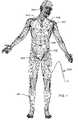
- FIG. 1is a wire-formed diagram of a generic human body showing a number of active implantable medical devices (AIMDs);
- AIMDsactive implantable medical devices
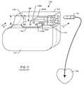
- FIG. 2is a perspective and somewhat schematic view of a prior art active implantable medical device (AIMD) including a lead wire directed to the heart of a patient;
- AIMDactive implantable medical device
- FIG. 3is an enlarged sectional view taken generally along the line 3 - 3 of FIG. 2 ;
- FIG. 4is a view taken generally along the line 4 - 4 of FIG. 3 ;
- FIG. 5is a perspective/isometric view of a prior art rectangular quadpolar feedthrough capacitor of the type shown in FIGS. 3 and 4 ;
- FIG. 6is sectional view taken generally along the line 6 - 6 of FIG. 5 ;
- FIG. 7is a sectional view taken generally along the line 7 - 7 of FIG. 5 .
- FIG. 8is a diagram of a unipolar active implantable medical device
- FIG. 9is a diagram similar to FIG. 8 , illustrating a bipolar AIMD system
- FIG. 10is a diagram similar to FIGS. 8 and 9 , illustrating a biopolar lead wire system with a distal TIP and RING, typically used in a cardiac pacemaker;
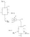
- FIG. 11is a schematic diagram showing a parallel combination of an inductor L and a capacitor C placed in series with the lead wire systems of FIGS. 8-10 ;
- FIG. 12is a chart illustrating calculation of frequency of resonance for the parallel tank circuit of FIG. 11 ;
- FIG. 13is a graph showing impedance versus frequency for the parallel tank band stop circuit of FIG. 11 ;
- FIG. 14is an equation for the impedance of an inductor in parallel with a capacitor
- FIG. 15is a chart illustrating reactance equations for the inductor and the capacitor of the parallel tank circuit of FIG. 11 ;
- FIG. 16is a schematic diagram illustrating the parallel tank circuit of FIG. 11 , except in this case the inductor and the capacitor have series resistive losses;
- FIG. 17is a diagram similar to FIG. 8 , illustrating the tank circuit/band stop filter added near a distal electrode
- FIG. 18is a schematic representation of the novel band stop tank filter of the present invention, using switches to illustrate its function at various frequencies;
- FIG. 19is a schematic diagram similar to FIG. 18 , illustrating the low frequency model of the band stop filter
- FIG. 20is a schematic diagram similar to FIGS. 18 and 19 , illustrating the model of the band stop filter of the present invention at its resonant frequency;
- FIG. 21is a schematic diagram similar to FIGS. 18-20 , illustrating a model of the band stop filter at high frequencies well above the resonant frequency;
- FIG. 22is a decision tree block diagram illustrating a process for designing the band stop filters of the present invention.
- FIG. 23is graph of insertion loss versus frequency for band stop filters having high Q inductors and differing quality “Q” factors;
- FIG. 24is a tracing of an exemplary patient x-ray showing an implanted pacemaker and cardioverter defibrillator and corresponding lead wire system;
- FIG. 25is a line drawings of an exemplary patent cardiac x-ray of a bi-ventricular lead wire system
- FIG. 26illustrates a bipolar cardiac pacemaker lead wire showing the distal TIP and the distal RING electrodes
- FIG. 27is an enlarged, fragmented schematic illustration of the area illustrated by the line 27 - 27 in FIG. 26 .
- FIG. 1illustrates of various types of active implantable medical devices 100 that are currently in use.
- FIG. 1is a wire formed diagram of a generic human body showing a number of implanted medical devices.
- 100 Ais a family of implantable hearing devices which can include the group of cochlear implants, piezoelectric sound bridge transducers and the like.
- 100 Bincludes an entire variety of neurostimulators and brain stimulators. Neurostimulators are used to stimulate the Vagus nerve, for example, to treat epilepsy, obesity and depression.
- Brain stimulatorsare similar to a pacemaker-like device and include electrodes implanted deep into the brain for sensing the onset of the seizure and also providing electrical stimulation to brain tissue to prevent the seizure from actually happening.
- 100 Cshows a cardiac pacemaker which is well-known in the art.
- 100 Dincludes the family of left ventricular assist devices (LVAD's), and artificial hearts, including the recently introduced artificial heart known as the Abiocor.
- 100 Eincludes an entire family of drug pumps which can be used for dispensing of insulin, chemotherapy drugs, pain medications and the like. Insulin pumps are evolving from passive devices to ones that have sensors and closed loop systems. That is, real time monitoring of blood sugar levels will occur. These devices tend to be more sensitive to EMI than passive pumps that have no sense circuitry or externally implanted lead wires.
- 100 Fincludes a variety of implantable bone growth stimulators for rapid healing of fractures.
- 100 Gincludes urinary incontinence devices.
- 100 Hincludes the family of pain relief spinal cord stimulators and anti-tremor stimulators.
- 100 Halso includes an entire family of other types of neurostimulators used to block pain.
- 100 Iincludes a family of implantable cardioverter defibrillators (ICD) devices and also includes the family of congestive heart failure devices (CHF). This is also known in the art as cardio resynchronization therapy devices, otherwise knows as CRT devices.
- ICDimplantable cardioverter defibrillators
- CHFcongestive heart failure devices
- the AIMD 100could, for example, be a cardiac pacemaker 100 C which is enclosed by a titanium housing 102 as indicated.
- the titanium housingis hermetically sealed, however there is a point where lead wires 104 must ingress and egress the hermetic seal.
- Hermetic terminal assembliesare well known and generally consist of a ferrule 108 which is laser welded to the titanium housing 102 of the AIMD 100 .
- the hermetic terminal assembly 106 with its associated EMI filteris better shown in FIG. 3 .
- four lead wiresare shown consisting of lead wire pair 104 a and 104 b and lead wire pair 104 c and 104 d . This is typical of what's known as a dual chamber bipolar cardiac pacemaker.
- the ISI connectors 110 that are designed to plug into the header block 112are low voltage (pacemaker) connectors covered by an ANSI/AAMI standard IS-1. Higher voltage devices, such as implantable cardioverter defibrillators, are covered by a standard known as the ANSI/AAMI DF-1. There is a new standard under development which will integrate both high voltage and low voltage connectors into a new miniature connector series known as the IS-4 series. These connectors are typically routed in a pacemaker application down into the right ventricle and right atrium of the heart 114 . There are also new generation devices that have been introduced to the market that couple lead wires to the outside of the left ventricle. These are known as biventricular devices and are very effective in cardiac resynchronization therapy (CRT) and treating congestive heart failure (CHF).
- CTRcardiac resynchronization therapy
- CHFcongestive heart failure
- the bipolar lead wires 104 a and 104 bthat could be routed, for example, to the distal TIP and RING into the right ventricle.
- the bipolar lead wires 104 c and 104 dcould be routed to a distal TIP and RING in the right atrium.
- AIMDsimplantable cardioverter defibrillators
- neurostimulatorsincluding deep brain stimulators, spinal cord stimulators, cochlear implants, incontinence stimulators and the like, and drug pumps.
- ICDsimplantable cardioverter defibrillators
- neurostimulatorsincluding deep brain stimulators, spinal cord stimulators, cochlear implants, incontinence stimulators and the like, and drug pumps.
- the present inventionis also applicable to a wide variety of minimally invasive AIMDs. For example, in certain hospital cath lab procedures, one can insert an AIMD for temporary use such as an ICD. Ventricular assist devices also can fall into this type of category. This list is not meant to be limiting, but is only example of the applications of the novel technology currently described herein.
- FIG. 3is an enlarged, fragmented cross-sectional view taken generally along line 3 - 3 of FIG. 2 .
- the RF telemetry pin 116 and the bipolar lead wires 104 a and 104 cwhich would be routed to the cardiac chambers by connecting these lead wires to the internal connectors 118 of the IS-1 header block 112 ( FIG. 2 ).
- These connectorsare designed to receive the plug 110 which allows the physicians to thread lead wires through the venous system down into the appropriate chambers of the heart 114 . It will be obvious to those skilled in the art that tunneling of deep brain electrodes or neurostimulators are equivalent.
- feedthrough capacitor 120which has been bonded to the hermetic terminal assembly 106 .
- feedthrough capacitorsare well known in the art and are described and illustrated in U.S. Pat. Nos. 5,333,095, 5,751,539, 5,978,204, 5,905,627, 5,959,829, 5,973,906, 5,978,204, 6,008,980, 6,159,560, 6,275,369, 6,424,234, 6,456,481, 6,473,291, 6,529,103, 6,566,978, 6,567,259, 6,643,903, 6,675,779, 6,765,780 and 6,882,248.
- a rectangular quadpolar feedthrough capacitor 120which has an external metallized termination surface 122 . It includes embedded electrode plate sets 124 and 126 . Electrode plate set 124 is known as the ground electrode plate set and is terminated at the outside of the capacitor 120 at the termination surface 122 . These ground electrode plates 124 are electrically and mechanically connected to the ferrule 108 of the hermetic terminal assembly 106 using a thermosetting conductive polyimide or equivalent material 128 (equivalent materials will include solders, brazes, conductive epoxies and the like). In turn, the hermetic seal terminal assembly 106 is designed to have its titanium ferrule 108 laser welded 130 to the overall housing 102 of the AIMD 100 . This forms a continuous hermetic seal thereby preventing body fluids from penetrating into and causing damage to the electronics of the AIMD.
- the lead wires 104 and insulator 136be hermetically sealed, such as by the gold brazes or glass seals 132 and 134 .
- the gold braze 132wets from the titanium ferrule 108 to the alumina ceramic insulator 136 .
- the ceramic alumina insulator 136is also gold brazed at 134 to each of the lead wires 104 .
- the RF telemetry pin 116is also gold brazed at 138 to the alumina ceramic insulator 136 . It will be obvious to those skilled in the art that there are a variety of other ways of making such a hermetic terminal. This would include glass sealing the leads into the ferrule directly without the need for the gold brazes.
- the RF telemetry pin 116has not been included in the area of the feedthrough capacitor 120 .
- the reason for thisis the feedthrough capacitor 120 is a very broadband single element EMI filter which would eliminate the desirable telemetry frequency.
- FIG. 4is a bottom view taken generally along line 4 - 4 in FIG. 3 .
- FIG. 5is an isometric view of the feedthrough capacitor 120 .
- the termination surface 122connects to the capacitor's internal ground plate set 124 .
- ground plate set 124which is typically silk-screened onto ceramic layers, is brought out and exposed to the termination surface 122 .
- the capacitor's four (quadpolar) active electrode plate sets 126are illustrated in FIG. 7 .
- the lead wires 104are in non-electrical communication with the ground electrode plate set 124 .
- each one of the lead wires 104is in electrical contact with its corresponding active electrode plate set 126 .
- the amount of capacitanceis determined by the overlap of the active electrode plate area 126 over the ground electrode plate area.
- the capacitance valueis also related to the dielectric thickness or spacing between the ground electrode set 124 and the active electrode set 126 . Reducing the dielectric thickness increases the capacitance significantly while at the same time reducing its voltage rating. This gives the designer many degrees of freedom in selecting the capacitance value.
- FIG. 8is a general diagram of a unipolar active implantable medical device system 100 .
- the housing 102 of the active implantable medical device 100is typically titanium, ceramic, stainless steel or the like. Inside of the device housing are the AIMD electronic circuits.
- AIMDsinclude a battery, but that is not always the case. For example, for a Bion, it can receive its energy from an external pulsing magnetic field.
- a lead wire 104is routed from the AIMD 100 to a point 140 where it is embedded in or affixed to body tissue.
- the distal TIP 140could be in the spinal cord.
- the distal electrode 140would be placed deep into the brain, etc.
- the distal electrode 140would typically be placed in the cardiac right ventricle.
- FIG. 9is very similar to FIG. 8 except that it is a bipolar system.
- the electric circuit return pathis between the two distal electrodes 140 and 140 ′.
- thiswould be known as a bipolar lead wire system with one of the electrodes known as the distal TIP 142 and the other electrode which would float in the blood pool known as the RING 144 (see FIG. 10 ).
- the electrical return path in FIG. 8is between the distal electrode 140 through body tissue to the conductive housing 102 of the implantable medical device 100 .
- FIG. 10illustrates a bipolar lead wire system with a distal TIP 142 and RING 144 typically as used in a cardiac pacemaker 100 C.
- the patientcould be exposed to the fields of an MRI scanner or other powerful emitter used during a medical diagnostic procedure.
- Currents that are directly induced in the lead wire system 104can cause heating by I 2 R losses in the lead wire system or by heating caused by current flowing in body tissue. If these currents become excessive, the associated heating can cause damage or even destructive ablation to body tissue.
- the distal TIP 142is designed to be implanted into or affixed to the actual myocardial tissue of the heart.
- the RING 144is designed to float in the blood pool. Because the blood is flowing and is thermally conductive, the RING 144 structure is substantially cooled. In theory, however, if the lead curves, the RING 144 could also touch and become encapsulated by body tissue.
- the distal TIP 142is always thermally insulated by surrounding body tissue and can readily heat up due to the RF pulse currents of an MRI field.
- FIG. 11is a schematic diagram showing a parallel combination of an inductor L and a capacitor C to be placed in the implantable lead wire systems 104 previously described. This combination forms a parallel tank circuit or band stop filter 146 which will resonate at a particular frequency (f r ).
- FIG. 12gives the frequency of resonance equation f r for the parallel tank circuit 146 of FIG. 11 : where f r is the frequency of resonance in hertz, L is the inductance in henries and C is the capacitance in farads.
- MRI systemsvary in static field strength from 0.5 Tesla all the way up to 3 Tesla with newer research machines going much higher. This is the force of the main static magnetic field.
- the frequency of the pulsed RF field associated with MRIis found by multiplying the static field in Teslas times 42.45. Accordingly, a 3 Tesla MRI system has a pulsed RF field of approximately 128 MHz.
- the inductor value Lis equal to one nanohenry. The one nanohenry comes from the fact that given the small geometries involved inside of the human body, a very large inductor will not be possible.
- the relationship between the parallel inductor L and capacitor Cis also very important.
- using a very high value of inductorresults in a high number of turns of very small wire.
- Using a high number of turns of very small diameter wireis contraindicated for two reasons. The first reason is that the long length of relatively small diameter wire results in a very high DC resistance for the inductor. This resistance is very undesirable because low frequency pacing or neurostimulator pulses would lose energy passing through the relatively high series resistance. This is also undesirable where the AIMD is sensing biologic signals.
- an air wound inductoris the ideal choice because it is not affected by MRI signals or fields. Because of the space limitations, however, the inductor will not be very volumetrically efficient. For this reason, it is preferable to keep the inductance value relatively low (in the order of 1 to 100 nanohenries).
- FIG. 13is a graph showing impedance versus frequency for the parallel tank, band stop filter circuit 146 of FIG. 11 .
- the impedance measured between points A and B for the parallel tank circuit 146 shown in FIG. 11is very low (zero) until one approaches the resonant frequency f r .
- these ideal componentscombine together to look like a very high or, ideally, an infinite impedance. The reason for this comes from the denominator of the equation Z ab for the impedance for the inductor in parallel with the capacitor shown as FIG. 14 .
- the inductive reactanceis equal to the capacitive reactance, the two imaginary vectors cancel each other and go to zero. Referring to the equations in FIGS.
- a cardiac pacemakerit would be possible, for example, in the case of a cardiac pacemaker, to design the cardiac pacemaker for compatibility with one single popular MRI system.
- the pacemaker lead wire systemhas been designed to be compatible with 3 Tesla MRI systems.
- a distal TIP band stop filter 146would be incorporated where the L and the C values have been carefully selected to be resonant at 128 MHz, presenting a high or almost infinite impedance at the MRI pulse frequency.
- FIG. 16is a schematic drawing of the parallel tank circuit 146 of FIG. 11 , except in this case the inductor L and the capacitor C are not ideal. That is, the capacitor C has its own internal resistance R C , which is otherwise known in the industry as dissipation factor or equivalent series resistance (ESR).
- the inductor Lalso has a resistance R L . For those that are experienced in passive components, one would realize that the inductor L would also have some parallel capacitance. This parasitic capacitance comes from the capacitance associated with adjacent turns. However, the inductance value contemplated is so low that one can assume that at MRI pulse frequencies, the inductor's parallel capacitance is negligible.
- the capacitor Calso has some internal inductance which would appear in series.
- the novel capacitors described beloware very small or coaxial and have negligible series inductance. Accordingly, the circuit shown in FIG. 16 is a very good approximation model for the novel parallel tank circuits 146 as described herein.
- the frequency fis close to zero (DC)
- biologic signalsare low frequency, typically between 10 Hz and 1000 Hz.
- the inductive reactance X Lwill be very close to zero ohms.
- the impedance between points A and B in FIG. 16will equal to R L .
- the resistance of the inductor (R L )should be kept as small as possible to minimize attenuation of biologic signals or attenuation of stimulation pulses to body tissues. This will allow biologic signals to pass through the band stop filter 146 freely. It also indicates that the amount of capacitive loss R C is not particularly important.
- FIG. 17is a drawing of the unipolar AIMD lead wire system, previously shown in FIG. 8 , with the band stop filter 146 of the present invention added near the distal electrode 140 .
- the presence of the tank circuit 146will present a very high impedance at one or more specific MRI RF pulse frequencies. This will prevent currents from circulating through the distal electrode 140 into body tissue at this selected frequency(s). This will provide a very high degree of important protection to the patient so that overheating does not cause tissue damage.
- FIG. 18is a representation of the novel band stop tank filter 146 using switches that open and close at various frequencies to illustrate its function.
- Inductor Lhas been replaced with a switch S L .
- the switch S LWhen the impedance of the inductor is quite low, the switch S L will be closed.
- the impedance or inductive reactance of the inductorWhen the impedance or inductive reactance of the inductor is high, the switch S L will be shown open.
- the capacitor element CWhen the capacitive reactance looks like a very low impedance, the capacitor switch S C will be shown closed. When the capacitive reactance is shown as a very high impedance, the switch S C will be shown open. This analogy is best understood by referring to FIGS. 19 , 20 and 21 .
- FIG. 19is the low frequency model of the band stop filter 146 .
- capacitorstend to look like open circuits and inductors tend to look like short circuits. Accordingly, switch S L is closed and switch S C is open. This is an indication that at frequencies below the resonant frequency of the band stop filter 146 that currents will flow only through the inductor element and its corresponding resistance R L .
- the implantable medical deviceis also sensing biological frequencies in the same frequency range.
- FIG. 20is a model of the novel band stop filter 146 at its resonant frequency.
- a parallel tank circuitis at resonance, it presents a very high impedance to the overall circuit. Accordingly, both switches S L and S C are shown open. For example, this is how the band stop filter 146 prevents the flow of MRI currents through pacemaker lead wires and/or into body tissue at a selected MRI RF pulsed frequency.
- FIG. 21is a model of the band stop filter 146 at high frequency.
- inductorstend to look like open circuits. Accordingly, switch S L is shown open.
- switch S Cis closed. It should be noted that real capacitors are not ideal and tend to degrade in performance at high frequency. This is due to the capacitor's equivalent series inductance and equivalent series resistance. Fortunately, for the present invention, it is not important how lossy (resistive) the capacitor element C gets at high frequency. This will only serve to attenuate unwanted electromagnetic interference from flowing in the lead wire system.
- the equivalent series resistance R C and resulting quality factor of the capacitor element Cis not nearly as important as the quality factor of the inductor element L.
- the equation for inductive reactance (X L )is given in FIG. 15 .
- the capacitor reactance equation (X C )is also given in FIG. 15 .
- FIG. 22is a decision tree block diagram that better illustrates the design process herein.
- Block 148is an initial decision step the designer must make.
- capacitanceFor illustrative purposes, we will start with a value of capacitance that is convenient. This value of capacitance is generally going to relate to the amount of space available in the AIMD lead wire system and other factors. These values for practical purposes generally range in capacitance value from a few tens of picofarads up to about 10,000 picofarads. This puts practical boundaries on the amount of capacitance that can be effectively packaged within the scope of the present invention. However, that is not intended to limit the general principles of the present invention, but just describe a preferred embodiment.
- block 150one does an assessment of the overall packaging requirements of a distal TIP 142 band stop filter 146 and then assumes a realizable capacitance value. So, in decision block 150 , we assume a capacitor value. We then solve the resonant tank equation f r from FIG.
- step 160If the capacitance value that is determined in step 160 is realizable, then one goes on and finalizes the design. However, if it is not realizable, then one can go back up to step 156 , assume a different value of L and go through the decision tree again. This is done over and over until one finds combinations of L and C that are practical for the overall design.
- the predetermined frequencywould be the MRI pulsed frequency.
- Efficiency of the overall tank circuit 146is also measured in terms of a quality factor, Q, although this factor is defined differently than the one previously mentioned for discrete capacitors and inductors.
- Qquality factor
- f ris the resonance frequency
- ⁇ f 3 dB shown as points a and b in FIG. 23is the bandwidth of the band stop filter 146 .
- Bandwidthis typically taken as the difference between the two measured frequencies, f 1 and f 2 , at the 3 dB loss points as measured on an insertion loss chart, and the resonance frequency is the average between f 1 and f 2 . As can be seen in this relationship, higher Q values result in a narrower 3 dB bandwidth.
- the “Q” or quality factor of the tank circuitis very important. As mentioned, it is desirable to have a very low loss circuit at low frequencies such that the biological signals not be undesirably attenuated.
- the quality factornot only determines the loss of the filter, but also affects its 3 dB bandwidth. If one does a plot of the filter response curve (Bode plot), the 3 dB bandwidth determines how sharply the filter will rise and fall. With reference to curve 166 of FIG. 23 , for a tank that is resonant at 128 MHz, an ideal response would be one that had infinite attenuation at 128 MHz, but had zero attenuation at low frequencies below 1 KHz.
- the performance of the circuitis directly related to the efficiency of both the inductor and the capacitor; the less efficient each component is, the more heat loss that results, and this can be expressed by the addition of resistor elements to the ideal circuit diagram.
- the effect of lower Q in the tank circuitis to broaden the resonance peak about the resonance frequency. By deliberately using a low Q capacitor, one can broaden the resonance such that a high impedance (high attenuation) is presented at multiple MRI RF frequencies, for example 64 MHz and 128 MHz.
- curve 164wherein a low resistive loss high Q inductor has been used in combination with a relatively high ESR low Q capacitor. This has a very desirable effect in that at very low frequencies, the impedance of the tank circuit 146 is essentially zero ohms (or zero dB loss). This means that biologic frequencies are not undesirably attenuated. However, one can see that the 3 db bandwidth is much larger. This is desirable as it will block multiple RF frequencies. As one goes even higher in frequency, curve 164 will desirably attenuate other high frequency EMI signals, such as those from cellular telephones, microwave ovens and the like.
- R CBy adding a separate discrete component in series with the capacitor element. For example, one could install a small capacitor chip that had a very low equivalent series resistance and place it in series with a resistor chip. This would be done to deliberately raise the value of R C in the circuit as shown in FIG. 17 . By carefully adjusting this value of R C , one could then achieve the ideal curve 164 as shown in FIG. 23 .
- FIG. 24is a tracing of an actual patient X-ray. This particular patient required both a cardiac pacemaker 100 C and an implantable cardioverter defibrillator 1001 .
- the corresponding implantable lead wire system 104makes for a very complicated antenna and loop coupling situation. The reader is referred to the article entitled, “Estimation of Effective Lead Loop Area for Implantable Pulse Generator and Implantable Cardioverter Defibrillators” provided by the AAMI Pacemaker EMC Task Force.
- the band stop filters 146 of the present inventionwould need to be placed at least in the distal TIP in the right atrium and the distal TIP in the right ventricle from the cardiac pacemaker.
- ICDimplantable cardioverter defibrillator
- ICDsimplantable cardioverter defibrillators
- FIG. 25is a line drawing of an actual patient cardiac X-ray of one of the newer bi-ventricular lead wire systems with various types of electrode TIPS shown.
- the new bi-ventricular systemsare being used to treat congestive heart failure, and make it possible to implant leads outside of the left ventricle. This makes for a very efficient pacing system; however, the implantable lead wire system 104 is quite complex.
- a lead wire system 104such as those described in FIGS. 8 , 9 , 10 and 11 , are exposed to a time varying electromagnetic field, electric currents can be induced into such lead wire systems.
- band stop filters 146would be required at each of the three distal TIPs and optionally at RING and SVC locations.
- FIG. 26illustrates a single chamber bipolar cardiac pacemaker lead wire showing the distal TIP 142 and the distal RING 144 electrodes. This is a spiral wound system where the RING coil 104 is wrapped around the TIP coil 104 ′. There are other types of pacemaker lead wire systems in which these two leads lay parallel to one another (known as a bifilar lead system).
- FIG. 27is a schematic illustration of the area 27 - 27 in FIG. 26 .
- band stop filters 146 and 146 ′have been placed in series with each of the respective TIP and RING circuits. Accordingly, at MRI pulsed frequencies, an open circuit will be presented thereby stopping the flow of undesirable RF current.
Landscapes
- Health & Medical Sciences (AREA)
- General Health & Medical Sciences (AREA)
- Physics & Mathematics (AREA)
- Engineering & Computer Science (AREA)
- Life Sciences & Earth Sciences (AREA)
- Biomedical Technology (AREA)
- Nuclear Medicine, Radiotherapy & Molecular Imaging (AREA)
- Animal Behavior & Ethology (AREA)
- Heart & Thoracic Surgery (AREA)
- Public Health (AREA)
- Veterinary Medicine (AREA)
- Cardiology (AREA)
- Radiology & Medical Imaging (AREA)
- Pathology (AREA)
- Condensed Matter Physics & Semiconductors (AREA)
- General Physics & Mathematics (AREA)
- Surgery (AREA)
- Plasma & Fusion (AREA)
- Otolaryngology (AREA)
- Medical Informatics (AREA)
- Molecular Biology (AREA)
- Electrotherapy Devices (AREA)
- Magnetic Resonance Imaging Apparatus (AREA)
- Filters And Equalizers (AREA)
- Neurology (AREA)
Abstract
Description
- (1) Safety Aspects of Cardiac Pacemakers in Magnetic Resonance Imaging”, a dissertation submitted to the Swiss Federal Institute of Technology Zurich presented by Roger Christoph Lüchinger, Zurich 2002;
- (2) “1. Dielectric Properties of Biological Tissues: Literature Survey”, by C. Gabriel, S. Gabriel and E. Cortout;
- (3) “II. Dielectric Properties of Biological Tissues: Measurements and the
Frequency Range 0 Hz to 20 GHz”, by S. Gabriel, R. W. Lau and C. Gabriel; - (4) “III. Dielectric Properties of Biological Tissues: Parametric Models for the Dielectric Spectrum of Tissues”, by S. Gabriel, R. W. Lau and C. Gabriel; and
- (5) “Advanced Engineering Electromagnetics, C. A. Balanis, Wiley, 1989;
- (6) Systems and Methods for Magnetic-Resonance-Guided Interventional Procedures, Patent Application Publication US 2003/0050557, Susil and Halperin et. al, published Mar. 13, 2003;
- (7) Multifunctional Interventional Devices for MRI: A Combined Electrophysiology/MRI Catheter, by, Robert C. Susil, Henry R. Halperin, Christopher J. Yeung, Albert C. Lardo and Ergin Atalar, MRI in Medicine, 2002; and
- (8) Multifunctional Interventional Devices for Use in MRI, U.S. Patent Application Ser. No. 60/283,725, filed Apr. 13, 2001.
- (1) Closure of the pacemaker reed switch. A pacemaker reed switch, which can also be a Hall Effect device, is designed to detect a permanent magnet held close to the patient's chest. This magnet placement allows a physician or even the patient to put the implantable medical device into what is known as the “magnet mode response.” The “magnet mode response” varies from one manufacturer to another, however, in general, this puts the pacemaker into a fixed rate or asynchronous pacing mode. This is normally done for short times and is very useful for diagnostic and clinical purposes. However, in some cases, when a pacemaker is brought into the bore or close to the MRI scanner, the MRI static field can make the pacemaker's internal reed switch close, which puts the pacemaker into a fixed rate or asynchronous pacing mode. Worse yet, the reed switch may bounce or oscillate. Asynchronous pacing may compete with the patient's underlying cardiac rhythm. This is one reason why patients have generally been advised not to undergo MRI. Fixed rate or asynchronous pacing for most patients is not an issue. However, in patients with unstable conditions, such as myocardial ischemia, there is a substantial risk for ventricular fibrillation during asynchronous pacing. In most modern pacemakers the magnetic reed switch (or Hall Effect device) function is programmable. If the magnetic reed switch response is switched off, then synchronous pacing is still possible even in strong magnetic fields. The possibility to open and re-close the reed switch in the main magnetic field by the gradient field cannot be excluded. However, it is generally felt that the reed switch will remain closed due to the powerful static magnetic field. It is theoretically possible for certain reed switch orientations at the gradient field to be capable of repeatedly closing and re-opening the reed switch.
- (2) Reed switch damage. Direct damage to the reed switch is theoretically possible, but has not been reported in any of the known literature. In an article written by Roger Christoph Lüchinger of Zurich, he reports on testing in which reed switches were exposed to the static magnetic field of MRI equipment. After extended exposure to these static magnetic fields, the reed switches functioned normally at close to the same field strength as before the test.
- (3) Pacemaker displacement. Some parts of pacemakers, such as the batteries and reed switch, contain ferrous magnetic materials and are thus subject to mechanical forces during MRI. Pacemaker displacement may occur in response to magnetic force or magnetic torque. There are several recent reports on modern pacemakers and ICDs that force and torque are not of concern for MRI systems up to 3 Tesla.
- (4) Radio frequency field. At the frequencies of interest in MRI, RF energy can be absorbed and converted to heat. The power deposited by RF pulses during MRI is complex and is dependent upon the power (Specific Absorption Rate (SAR) Level) and duration of the RF pulse, the transmitted frequency, the number of RF pulses applied per unit time, and the type of configuration of the RF transmitter coil used. The amount of heating also depends upon the volume of tissue imaged, the electrical resistivity of tissue and the configuration of the anatomical region imaged. There are also a number of other variables that depend on the placement in the human body of the AIMD and its associated lead wire(s). For example, it will make a difference how much current is induced into a pacemaker lead wire system as to whether it is a left or right pectoral implant. In addition, the routing of the lead and the lead length are also very critical as to the amount of induced current and heating that would occur. Also, distal TIP design is very important as the distal TIP itself can act as its own antenna wherein eddy currents can create heating. The cause of heating in an MRI environment is two fold: (a) RF field coupling to the lead can occur which induces significant local heating; and (b) currents induced between the distal TIP and tissue during MRI RF pulse transmission sequences can cause local Ohms Law heating in tissue next to the distal TIP electrode of the implanted lead. The RF field of an MRI scanner can produce enough energy to induce lead wire currents sufficient to destroy some of the adjacent myocardial tissue. Tissue ablation has also been observed. The effects of this heating are not readily detectable by monitoring during the MRI. Indications that heating has occurred would include an increase in pacing threshold, venous ablation, Larynx or e ablation, myocardial perforation and lead penetration, or even arrhythmias caused by scar tissue. Such long term heating effects of MRI have not been well studied yet for all types of AIMD lead wire geometries. There can also be localized heating problems associated with various types of electrodes in addition to TIP electrodes. This includes RING electrodes or PAD electrodes. RING electrodes are commonly used with a wide variety of implanted devices including cardiac pacemakers, and neurostimulators, and the like. PAD electrodes are very common in neurostimulator applications. For example, spinal cord stimulators or deep brain stimulators can include a plurality of PAD electrodes to make contact with nerve tissue. A good example of this also occurs in a cochlear implant. In a typical cochlear implant there would be sixteen RING electrodes that the position places by pushing the electrode up into the cochlea. Several of these RING electrodes make contact with auditory nerves.
- (5) Alterations of pacing rate due to the applied radio frequency field. It has been observed that the RF field may induce undesirable fast pacing (QRS complex) rates. There are various mechanisms which have been proposed to explain rapid pacing: direct tissue stimulation, interference with pacemaker electronics or pacemaker reprogramming (or reset). In all of these cases, it is very desirable to raise the lead system impedance (at the MRI RF pulsed frequency) to make an EMI filter feedthrough capacitor more effective and thereby provide a higher degree of protection to AIMD electronics. This will make alterations in pacemaker pacing rate and/or pacemaker reprogramming much more unlikely.
- (6) Time-varying magnetic gradient fields. The contribution of the time-varying gradient to the total strength of the MRI magnetic field is negligible, however, pacemaker systems could be affected because these fields are rapidly applied and removed. The time rate of change of the magnetic field is directly related to how much electromagnetic force and hence current can be induced into a lead wire system. Lüchinger reports that even using today's gradient systems with a time-varying field up to 50 Tesla per second, the induced currents are likely to stay below the biological thresholds for cardiac fibrillation. A theoretical upper limit for the induced voltage by the time-varying magnetic gradient field is 20 volts. Such a voltage during more than 0.1 milliseconds could be enough energy to directly pace the heart.
- (7) Heating. Currents induced by time-varying magnetic gradient fields may lead to local heating. Researchers feel that the calculated heating effect of the gradient field is much less as compared to that caused by the RF field and therefore for the purposes herein may be neglected.
Claims (18)
Priority Applications (1)
| Application Number | Priority Date | Filing Date | Title |
|---|---|---|---|
| US11/743,000US7363090B2 (en) | 2001-04-13 | 2007-05-01 | Band stop filter employing a capacitor and an inductor tank circuit to enhance MRI compatibility of active implantable medical devices |
Applications Claiming Priority (4)
| Application Number | Priority Date | Filing Date | Title |
|---|---|---|---|
| US28372501P | 2001-04-13 | 2001-04-13 | |
| US10/123,534US7844319B2 (en) | 1998-11-04 | 2002-04-15 | Systems and methods for magnetic-resonance-guided interventional procedures |
| US11/423,073US8244370B2 (en) | 2001-04-13 | 2006-06-08 | Band stop filter employing a capacitor and an inductor tank circuit to enhance MRI compatibility of active medical devices |
| US11/743,000US7363090B2 (en) | 2001-04-13 | 2007-05-01 | Band stop filter employing a capacitor and an inductor tank circuit to enhance MRI compatibility of active implantable medical devices |
Related Parent Applications (2)
| Application Number | Title | Priority Date | Filing Date |
|---|---|---|---|
| US10/123,534Continuation-In-PartUS7844319B2 (en) | 1998-11-04 | 2002-04-15 | Systems and methods for magnetic-resonance-guided interventional procedures |
| US11/423,073ContinuationUS8244370B2 (en) | 1998-11-04 | 2006-06-08 | Band stop filter employing a capacitor and an inductor tank circuit to enhance MRI compatibility of active medical devices |
Publications (2)
| Publication Number | Publication Date |
|---|---|
| US20070288058A1 US20070288058A1 (en) | 2007-12-13 |
| US7363090B2true US7363090B2 (en) | 2008-04-22 |
Family
ID=38832247
Family Applications (11)
| Application Number | Title | Priority Date | Filing Date |
|---|---|---|---|
| US11/423,073Expired - Fee RelatedUS8244370B2 (en) | 1998-11-04 | 2006-06-08 | Band stop filter employing a capacitor and an inductor tank circuit to enhance MRI compatibility of active medical devices |
| US11/743,000Expired - Fee RelatedUS7363090B2 (en) | 2001-04-13 | 2007-05-01 | Band stop filter employing a capacitor and an inductor tank circuit to enhance MRI compatibility of active implantable medical devices |
| US12/170,811Active2026-05-12US8897887B2 (en) | 2001-04-13 | 2008-07-10 | Band stop filter employing a capacitor and an inductor tank circuit to enhance MRI compatibility of active medical devices |
| US12/776,644AbandonedUS20100222857A1 (en) | 2001-04-13 | 2010-05-10 | Band stop filter employing a capacitor and an inductor tank circuit to enhance MRI compatibility of active medical devices |
| US12/776,617Expired - Fee RelatedUS8275466B2 (en) | 2006-06-08 | 2010-05-10 | Band stop filter employing a capacitor and an inductor tank circuit to enhance MRI compatibility of active medical devices |
| US13/074,186Expired - Fee RelatedUS8180448B2 (en) | 2006-06-08 | 2011-03-29 | Tank filters placed in series with the lead wires or circuits of active medical devices to enhance MRI compatibility |
| US13/215,722AbandonedUS20110306860A1 (en) | 2001-04-13 | 2011-08-23 | Band Stop Filter Employing a Capacitor and an Inductor Tank Circuit to Enhance MRI Compatibility of Active Medical Devices |
| US13/275,740AbandonedUS20120053667A1 (en) | 2006-06-08 | 2011-10-18 | Medical lead having a bandstop filter employing a capacitor and an inductor tank circuit to enhance mri compatibility |
| US13/275,642AbandonedUS20120046723A1 (en) | 2001-04-13 | 2011-10-18 | Medical lead having a bandstop filter employing a capacitor and an inductor tank circuit to enhance mri compatibility |
| US13/440,382Expired - Fee RelatedUS8364283B2 (en) | 2001-04-13 | 2012-04-05 | Band stop filter employing a capacitor and an inductor tank circuit to enhance MRI compatibility of active medical devices |
| US13/544,461Active2033-06-30US9119968B2 (en) | 2006-06-08 | 2012-07-09 | Band stop filter employing a capacitor and an inductor tank circuit to enhance MRI compatibility of active medical devices |
Family Applications Before (1)
| Application Number | Title | Priority Date | Filing Date |
|---|---|---|---|
| US11/423,073Expired - Fee RelatedUS8244370B2 (en) | 1998-11-04 | 2006-06-08 | Band stop filter employing a capacitor and an inductor tank circuit to enhance MRI compatibility of active medical devices |
Family Applications After (9)
| Application Number | Title | Priority Date | Filing Date |
|---|---|---|---|
| US12/170,811Active2026-05-12US8897887B2 (en) | 2001-04-13 | 2008-07-10 | Band stop filter employing a capacitor and an inductor tank circuit to enhance MRI compatibility of active medical devices |
| US12/776,644AbandonedUS20100222857A1 (en) | 2001-04-13 | 2010-05-10 | Band stop filter employing a capacitor and an inductor tank circuit to enhance MRI compatibility of active medical devices |
| US12/776,617Expired - Fee RelatedUS8275466B2 (en) | 2006-06-08 | 2010-05-10 | Band stop filter employing a capacitor and an inductor tank circuit to enhance MRI compatibility of active medical devices |
| US13/074,186Expired - Fee RelatedUS8180448B2 (en) | 2006-06-08 | 2011-03-29 | Tank filters placed in series with the lead wires or circuits of active medical devices to enhance MRI compatibility |
| US13/215,722AbandonedUS20110306860A1 (en) | 2001-04-13 | 2011-08-23 | Band Stop Filter Employing a Capacitor and an Inductor Tank Circuit to Enhance MRI Compatibility of Active Medical Devices |
| US13/275,740AbandonedUS20120053667A1 (en) | 2006-06-08 | 2011-10-18 | Medical lead having a bandstop filter employing a capacitor and an inductor tank circuit to enhance mri compatibility |
| US13/275,642AbandonedUS20120046723A1 (en) | 2001-04-13 | 2011-10-18 | Medical lead having a bandstop filter employing a capacitor and an inductor tank circuit to enhance mri compatibility |
| US13/440,382Expired - Fee RelatedUS8364283B2 (en) | 2001-04-13 | 2012-04-05 | Band stop filter employing a capacitor and an inductor tank circuit to enhance MRI compatibility of active medical devices |
| US13/544,461Active2033-06-30US9119968B2 (en) | 2006-06-08 | 2012-07-09 | Band stop filter employing a capacitor and an inductor tank circuit to enhance MRI compatibility of active medical devices |
Country Status (5)
| Country | Link |
|---|---|
| US (11) | US8244370B2 (en) |
| EP (2) | EP2165734A3 (en) |
| JP (1) | JP2009537276A (en) |
| CN (1) | CN101325985B (en) |
| WO (1) | WO2007145671A2 (en) |
Cited By (159)
| Publication number | Priority date | Publication date | Assignee | Title |
|---|---|---|---|---|
| US20050043761A1 (en)* | 2000-04-20 | 2005-02-24 | Patrick Connelly | MRI-compatible implantable device |
| US20050222656A1 (en)* | 2004-03-30 | 2005-10-06 | Wahlstrand Carl D | MRI-safe implantable medical device |
| US20050222658A1 (en)* | 2004-03-30 | 2005-10-06 | Medtronic, Inc. | Lead electrode for use in an MRI-safe implantable medical device |
| US20050283213A1 (en)* | 2003-08-25 | 2005-12-22 | Biophan Technologies, Inc. | Medical device with an electrically conductive anti-antenna member |
| US20060100506A1 (en)* | 1998-11-04 | 2006-05-11 | Johns Hopkins University School Of Medicine | System and method for magnetic-resonance-guided electrophysiologic and ablation procedures |
| US20060200218A1 (en)* | 2005-02-01 | 2006-09-07 | Wahlstrand Carl D | Extensible implantable medical lead |
| US20060247748A1 (en)* | 2005-04-29 | 2006-11-02 | Medtronic, Inc. | Lead electrode for use in an MRI-safe implantable medical device |
| US20070085630A1 (en)* | 2005-10-19 | 2007-04-19 | Avx Corporation. | Asymmetrical filter |
| US20070088416A1 (en)* | 2001-04-13 | 2007-04-19 | Surgi-Vision, Inc. | Mri compatible medical leads |
| US20080033497A1 (en)* | 2005-11-04 | 2008-02-07 | Cherik Bulkes | Mri compatible implanted electronic medical device and lead |
| US20080051854A1 (en)* | 2005-11-04 | 2008-02-28 | Cherik Bulkes | Mri compatible implanted electronic medical device with power and data communication capability |
| US20080132985A1 (en)* | 2006-11-30 | 2008-06-05 | Cardiac Pacemakers, Inc. | Rf rejecting lead |
| US20080195186A1 (en)* | 2007-02-14 | 2008-08-14 | Bernard Li | Continuous conductive materials for electromagnetic shielding |
| US20080195187A1 (en)* | 2007-02-14 | 2008-08-14 | Bernard Li | Discontinuous conductive filler polymer-matrix composites for electromagnetic shielding |
| US20080269863A1 (en)* | 2007-04-25 | 2008-10-30 | Medtronic, Inc. | Lead or lead extension having a conductive body and conductive body contact |
| US20080269831A1 (en)* | 2007-04-25 | 2008-10-30 | Erickson John H | Implantable pulse generator comprising mri current limiting windings in header structure |
| US20090179716A1 (en)* | 2008-01-09 | 2009-07-16 | Anaren, Inc. | RF Filter Device |
| US20090198314A1 (en)* | 2008-02-06 | 2009-08-06 | Foster Arthur J | Lead with mri compatible design features |
| WO2009117599A2 (en) | 2008-03-20 | 2009-09-24 | Greatbatch Ltd. | Shielded three-terminal flat-through emi/energy dissipating filter |
| US20090259265A1 (en)* | 2002-02-28 | 2009-10-15 | Greatbatch Ltd. | Electronic network components utilizing biocompatible conductive adhesives for direct body fluid exposure |
| US20090281608A1 (en)* | 2008-05-09 | 2009-11-12 | Cardiac Pacemakers, Inc. | Medical lead coil conductor with spacer element |
| US20090312835A1 (en)* | 2008-06-17 | 2009-12-17 | Greatbatch Ltd. | Dielectric fluid filled active implantable medical devices |
| US20100001387A1 (en)* | 2007-03-23 | 2010-01-07 | Fujitsu Limited | Electronic device, electronic apparatus mounted with electronic device, article equipped with electronic device and method of producing electronic device |
| EP2143466A2 (en) | 2008-07-10 | 2010-01-13 | Greatbatch Ltd. | Transient voltage/current protection system for electronic circuits associated with implanted leads |
| US20100016934A1 (en)* | 2007-03-07 | 2010-01-21 | Koninklijke Philips Electronics N.V. | Apparatus and method for applying energy within an object |
| US20100016936A1 (en)* | 2001-04-13 | 2010-01-21 | Greatbatch Ltd. | Frequency selective passive component networks for implantable leads of active implantable medical devices utilizing an energy dissipating surface |
| US20100023000A1 (en)* | 2002-04-15 | 2010-01-28 | Greatbatch Ltd. | Frequency selective passive component networks for implantable leads of active implantable medical devices utilizing an energy dissipating surface |
| US20100094364A1 (en)* | 2008-10-09 | 2010-04-15 | Boston Scientific Neuromodulation Corporation | Electrical stimulation leads having rf compatibility and methods of use and manufacture |
| US20100100164A1 (en)* | 2006-11-09 | 2010-04-22 | Greatbatch Ltd. | Capacitor and inductor elements physically disposed in series whose lumped parameters are electrically connected in parallel to form a bandstop filter |
| US20100114281A1 (en)* | 2008-10-31 | 2010-05-06 | Greatbatch Ltd. | Mri conditionally safe lead extension and methods |
| EP2186541A1 (en) | 2008-11-18 | 2010-05-19 | Greatbatch Ltd. | Satellite therapy delivery system for brain neuromodulation |
| US20100125312A1 (en)* | 2008-11-18 | 2010-05-20 | Greatbatch Ltd. | Satellite therapy delivery system for brain neuromodulation |
| US7734354B1 (en) | 2006-08-04 | 2010-06-08 | Advanced Neuromodulation Systems, Inc. | Stimulation lead, stimulation system, and method for limiting MRI induced current in a stimulation lead |
| EP2193823A2 (en) | 2008-11-12 | 2010-06-09 | Greatbatch Ltd. | Passsive electronic network components designed for direct body fluid exposure |
| US20100160997A1 (en)* | 2001-04-13 | 2010-06-24 | Greatbatch Ltd. | Tuned energy balanced system for minimizing heating and/or to provide emi protection of implanted leads in a high power electromagnetic field environment |
| US20100168821A1 (en)* | 2001-04-13 | 2010-07-01 | Greatbatch Ltd. | Switched diverter circuits for minimizing heating of an implanted lead in a high power electromagnetic field environment |
| US20100185263A1 (en)* | 2008-03-20 | 2010-07-22 | Greatbatch Ltd. | Rf activated aimd telemetry transceiver |
| US20100191236A1 (en)* | 2001-04-13 | 2010-07-29 | Greatbatch Ltd. | Switched diverter circuits for minimizing heating of an implanted lead and/or providing emi protection in a high power electromagnetic field environment |
| US20100208397A1 (en)* | 2008-12-17 | 2010-08-19 | Greatbatch Ltd. | Switched safety protection circuit for an aimd system during exposure to high power electromagnetic fields |
| US20100217366A1 (en)* | 2009-02-26 | 2010-08-26 | Pacesetter, Inc. | Implantable Medical Lead Circuitry and Methods for Reducing Heating and/or Induced Current |
| US20100234929A1 (en)* | 2009-03-12 | 2010-09-16 | Torsten Scheuermann | Thin profile conductor assembly for medical device leads |
| US20100249892A1 (en)* | 2009-03-26 | 2010-09-30 | Cherik Bulkes | Mri compatible implanted lead-electrode interface |
| EP2258442A1 (en) | 2009-06-03 | 2010-12-08 | Greatbatch Ltd. | Dielectric fluid filled active implantable medical devices |
| US7853332B2 (en) | 2005-04-29 | 2010-12-14 | Medtronic, Inc. | Lead electrode for use in an MRI-safe implantable medical device |
| US20100324640A1 (en)* | 2006-11-09 | 2010-12-23 | Greatbatch Ltd. | Electrically isolating electrical components in a medical electrical lead with an active fixation electrode |
| US20100331942A1 (en)* | 2009-06-29 | 2010-12-30 | Pacesetter, Inc. | Mri compatible implantable medical lead and method of making same |
| US20100331936A1 (en)* | 2009-06-26 | 2010-12-30 | Christopher Perrey | Medical device lead including a unifilar coil with improved torque transmission capacity and reduced mri heating |
| EP2269688A1 (en) | 2009-07-02 | 2011-01-05 | Greatbatch Ltd. | Transient voltage suppression circuit for an implanted RFID chip |
| US20110029054A1 (en)* | 2009-07-31 | 2011-02-03 | Tranchina Benjamin A | Method for fabricating a stimulation lead to reduce mri heating and a stimulation lead for use within mri systems |
| US20110046707A1 (en)* | 2009-03-04 | 2011-02-24 | Imricor Medical Systems Inc. | Mri compatible electrode circuit |
| US7937148B2 (en) | 2005-10-14 | 2011-05-03 | Nanostim, Inc. | Rate responsive leadless cardiac pacemaker |
| US20110106218A1 (en)* | 2009-10-30 | 2011-05-05 | Medtronic, Inc. | Controlling effects caused by exposure of an implantable medical device to a disruptive energy field |
| US7962224B1 (en) | 2007-02-05 | 2011-06-14 | Advanced Neuromodulation Systems, Inc. | Stimulation lead, stimulation system, and method for limiting MRI-induced current in a stimulation lead |
| US20110144734A1 (en)* | 2001-04-13 | 2011-06-16 | Greatbatch Ltd. | Medical lead system utilizing electromagnetic bandstop filters |
| US20110147062A1 (en)* | 2009-12-22 | 2011-06-23 | Greatbatch Ltd. | Feedthrough flat-through capacitor |
| US20110160809A1 (en)* | 2009-12-30 | 2011-06-30 | Cox Timothy J | Pulse charge limiter |
| US20110196463A1 (en)* | 2010-02-11 | 2011-08-11 | Kerstin Taeubert | Electrode device for active medical implants |
| US20110196460A1 (en)* | 2010-02-11 | 2011-08-11 | Ingo Weiss | Implantable element and electronic implant |
| US20110196462A1 (en)* | 2010-02-11 | 2011-08-11 | Ingo Weiss | Electrode device for active medical implant |
| US20110196229A1 (en)* | 2010-02-11 | 2011-08-11 | Ingo Weiss | Adaptation probe for insertion into implanted electrode devices of active medical implants and set composed of an implantable electrode device and an adaptation probe |
| US20110230943A1 (en)* | 2010-03-17 | 2011-09-22 | Greatbatch Ltd. | Implantable lead for an active medical device having an inductor design minimizing eddy current losses |
| US8032230B1 (en) | 2007-10-09 | 2011-10-04 | Advanced Neuromodulation Systems, Inc. | Stimulation lead, stimulation system, and method for limiting MRI induced current in a stimulation lead |
| USRE42856E1 (en) | 2002-05-29 | 2011-10-18 | MRI Interventions, Inc. | Magnetic resonance probes |
| US20110270369A1 (en)* | 2010-04-30 | 2011-11-03 | Mohac Tekmen | Medical electrical lead with conductive sleeve head |
| EP2384786A1 (en) | 2010-05-05 | 2011-11-09 | BIOTRONIK SE & Co. KG | Electrode lead in particular for use with a medical implant |
| US8095224B2 (en) | 2009-03-19 | 2012-01-10 | Greatbatch Ltd. | EMI shielded conduit assembly for an active implantable medical device |
| EP2415499A1 (en) | 2010-08-02 | 2012-02-08 | Greatbatch Ltd. | Multilayer helical wave filter for medical therapeutic or diagnostic applications |
| US8224462B2 (en) | 2005-11-11 | 2012-07-17 | Greatbatch Ltd. | Medical lead system utilizing electromagnetic bandstop filters |
| US20120191167A1 (en)* | 2011-01-26 | 2012-07-26 | Boston Scientific Neuromodulation Corporation | Systems and methods for making and using electrical stimulation systems with improved rf compatibility |
| EP2486952A1 (en) | 2011-02-14 | 2012-08-15 | Greatbatch Ltd. | Medical lead system utilizing electromagnetic bandstop filters |
| EP2495014A1 (en) | 2011-03-01 | 2012-09-05 | Greatbatch Ltd. | RF filter for an active implantable medical device (AIMD) for handling high RF power induced in an associated implanted lead from an external RF field |
| US8285396B2 (en) | 2009-01-05 | 2012-10-09 | Kenergy, Inc. | MRI compatible electrical lead for an implanted electronic medical device |
| US8335572B2 (en) | 2009-10-08 | 2012-12-18 | Cardiac Pacemakers, Inc. | Medical device lead including a flared conductive coil |
| US8369930B2 (en) | 2009-06-16 | 2013-02-05 | MRI Interventions, Inc. | MRI-guided devices and MRI-guided interventional systems that can track and generate dynamic visualizations of the devices in near real time |
| US8391994B2 (en) | 2009-12-31 | 2013-03-05 | Cardiac Pacemakers, Inc. | MRI conditionally safe lead with low-profile multi-layer conductor for longitudinal expansion |
| EP2414034A4 (en)* | 2009-03-31 | 2013-05-01 | St Jude Medical | IMPLANTABLE MEDICAL PROBE COMPATIBLE WITH MRI AND PROVIDED WITH ROTATIONAL CONTROL ELEMENT |
| US8437863B2 (en) | 2008-12-19 | 2013-05-07 | St. Jude Medical Ab | Electrode lead |
| US20130123884A1 (en)* | 2009-10-09 | 2013-05-16 | Masoud Ameri | Mri compatible medical device lead including transmission line notch filters |
| EP2594314A1 (en) | 2011-11-17 | 2013-05-22 | Greatbatch Ltd. | Composite RF attenuator for a medical lead |
| US20130200162A1 (en)* | 2011-01-14 | 2013-08-08 | Murata Manufacturing Co., Ltd. | Rfid chip package and rfid tag |
| US8527068B2 (en) | 2009-02-02 | 2013-09-03 | Nanostim, Inc. | Leadless cardiac pacemaker with secondary fixation capability |
| US8543205B2 (en) | 2010-10-12 | 2013-09-24 | Nanostim, Inc. | Temperature sensor for a leadless cardiac pacemaker |
| US8565899B1 (en) | 2012-04-18 | 2013-10-22 | Cochlear Limited | Implantable prosthesis configuration to control heat dissipation from prosthesis components |
| US8612021B2 (en) | 2011-02-10 | 2013-12-17 | Medtronic, Inc. | Magnetic resonance imaging compatible medical electrical lead and method of making the same |
| US8615310B2 (en) | 2010-12-13 | 2013-12-24 | Pacesetter, Inc. | Delivery catheter systems and methods |
| US8666512B2 (en) | 2011-11-04 | 2014-03-04 | Cardiac Pacemakers, Inc. | Implantable medical device lead including inner coil reverse-wound relative to shocking coil |
| US8712544B2 (en) | 2001-04-13 | 2014-04-29 | Greatbatch Ltd. | Electromagnetic shield for a passive electronic component in an active medical device implantable lead |
| US8731685B2 (en) | 2007-12-06 | 2014-05-20 | Cardiac Pacemakers, Inc. | Implantable lead having a variable coil conductor pitch |
| US8761899B2 (en) | 2009-03-04 | 2014-06-24 | Imricor Medical Systems, Inc. | MRI compatible conductive wires |
| US8798767B2 (en) | 2009-12-31 | 2014-08-05 | Cardiac Pacemakers, Inc. | MRI conditionally safe lead with multi-layer conductor |
| US8805540B2 (en) | 2009-03-04 | 2014-08-12 | Imricor Medical Systems, Inc. | MRI compatible cable |
| US20140240060A1 (en)* | 2006-06-08 | 2014-08-28 | Greatbatch Ltd. | Emi filter employing a self-resonant inductor bandstop filter having optimum inductance and capacitance values |
| US8825181B2 (en) | 2010-08-30 | 2014-09-02 | Cardiac Pacemakers, Inc. | Lead conductor with pitch and torque control for MRI conditionally safe use |
| US8825179B2 (en) | 2012-04-20 | 2014-09-02 | Cardiac Pacemakers, Inc. | Implantable medical device lead including a unifilar coiled cable |
| US8831743B2 (en) | 2009-03-04 | 2014-09-09 | Imricor Medical Systems, Inc. | MRI compatible electrode circuit |
| US8834657B2 (en) | 2010-08-20 | 2014-09-16 | Kenergy, Inc. | Method of manufacturing an mri compatible conductive lead body |
| US8843213B2 (en) | 2009-03-04 | 2014-09-23 | Imricor Medical Systems, Inc. | MRI compatible co-radially wound lead assembly |
| US8855788B2 (en) | 2009-03-04 | 2014-10-07 | Imricor Medical Systems, Inc. | MRI compatible electrode circuit |
| US8882763B2 (en) | 2010-01-12 | 2014-11-11 | Greatbatch Ltd. | Patient attached bonding strap for energy dissipation from a probe or a catheter during magnetic resonance imaging |
| US8903505B2 (en) | 2006-06-08 | 2014-12-02 | Greatbatch Ltd. | Implantable lead bandstop filter employing an inductive coil with parasitic capacitance to enhance MRI compatibility of active medical devices |
| US8954168B2 (en) | 2012-06-01 | 2015-02-10 | Cardiac Pacemakers, Inc. | Implantable device lead including a distal electrode assembly with a coiled component |
| EP2835148A1 (en) | 2013-08-04 | 2015-02-11 | Greatbatch Ltd. | Multilayer planar spiral inductor filter for medical, therapeutic or diagnostic applications |
| US8958889B2 (en) | 2012-08-31 | 2015-02-17 | Cardiac Pacemakers, Inc. | MRI compatible lead coil |
| US8983623B2 (en) | 2012-10-18 | 2015-03-17 | Cardiac Pacemakers, Inc. | Inductive element for providing MRI compatibility in an implantable medical device lead |
| US8989840B2 (en) | 2004-03-30 | 2015-03-24 | Medtronic, Inc. | Lead electrode for use in an MRI-safe implantable medical device |
| US8996126B2 (en) | 2009-02-04 | 2015-03-31 | Greatbatch Ltd. | Composite RF current attenuator for a medical lead |
| US9014815B2 (en) | 2009-11-19 | 2015-04-21 | Medtronic, Inc. | Electrode assembly in a medical electrical lead |
| US9020611B2 (en) | 2010-10-13 | 2015-04-28 | Pacesetter, Inc. | Leadless cardiac pacemaker with anti-unscrewing feature |
| US9031670B2 (en) | 2006-11-09 | 2015-05-12 | Greatbatch Ltd. | Electromagnetic shield for a passive electronic component in an active medical device implantable lead |
| EP2875844A1 (en) | 2013-11-25 | 2015-05-27 | BIOTRONIK SE & Co. KG | Implantable electrode arrangement, in particular for cardiological devices, such as cardiac pacemakers |
| US9061132B1 (en) | 2011-02-18 | 2015-06-23 | Greatbatch Ltd. | Positioning of a medical device conductor in an MRI environment to reduce RF induced current |
| US9060692B2 (en) | 2010-10-12 | 2015-06-23 | Pacesetter, Inc. | Temperature sensor for a leadless cardiac pacemaker |
| US9093974B2 (en) | 2012-09-05 | 2015-07-28 | Avx Corporation | Electromagnetic interference filter for implanted electronics |
| US9101782B2 (en) | 2011-08-19 | 2015-08-11 | Greatbatch Ltd. | Implantable cardioverter defibrillator designed for use in a magnetic resonance imaging environment |
| US9108066B2 (en) | 2008-03-20 | 2015-08-18 | Greatbatch Ltd. | Low impedance oxide resistant grounded capacitor for an AIMD |
| US9126037B2 (en) | 2006-04-26 | 2015-09-08 | Medtronic, Inc. | Medical electrical lead including an inductance augmenter |
| US9126032B2 (en) | 2010-12-13 | 2015-09-08 | Pacesetter, Inc. | Pacemaker retrieval systems and methods |
| US9155877B2 (en) | 2004-03-30 | 2015-10-13 | Medtronic, Inc. | Lead electrode for use in an MRI-safe implantable medical device |
| US9168383B2 (en) | 2005-10-14 | 2015-10-27 | Pacesetter, Inc. | Leadless cardiac pacemaker with conducted communication |
| US9186499B2 (en) | 2009-04-30 | 2015-11-17 | Medtronic, Inc. | Grounding of a shield within an implantable medical lead |
| US9242102B2 (en) | 2010-12-20 | 2016-01-26 | Pacesetter, Inc. | Leadless pacemaker with radial fixation mechanism |
| US9254380B2 (en) | 2009-10-19 | 2016-02-09 | Cardiac Pacemakers, Inc. | MRI compatible tachycardia lead |
| US9259290B2 (en) | 2009-06-08 | 2016-02-16 | MRI Interventions, Inc. | MRI-guided surgical systems with proximity alerts |
| AU2014253481B2 (en)* | 2009-03-04 | 2016-02-25 | Imricor Medical Systems, Inc. | MRI compatible electrode circuit |
| US9295828B2 (en) | 2001-04-13 | 2016-03-29 | Greatbatch Ltd. | Self-resonant inductor wound portion of an implantable lead for enhanced MRI compatibility of active implantable medical devices |
| US9302101B2 (en) | 2004-03-30 | 2016-04-05 | Medtronic, Inc. | MRI-safe implantable lead |
| US9427596B2 (en) | 2013-01-16 | 2016-08-30 | Greatbatch Ltd. | Low impedance oxide resistant grounded capacitor for an AIMD |
| US9431814B2 (en) | 2012-02-15 | 2016-08-30 | Cardiac Pacemakers, Inc. | Ferrule for implantable medical device |
| US9463317B2 (en) | 2012-04-19 | 2016-10-11 | Medtronic, Inc. | Paired medical lead bodies with braided conductive shields having different physical parameter values |
| US9463329B2 (en) | 2008-03-20 | 2016-10-11 | Greatbatch Ltd. | Shielded three-terminal flat-through EMI/energy dissipating filter with co-fired hermetically sealed feedthrough |
| US9468750B2 (en) | 2006-11-09 | 2016-10-18 | Greatbatch Ltd. | Multilayer planar spiral inductor filter for medical therapeutic or diagnostic applications |
| EP3081258A1 (en) | 2015-04-16 | 2016-10-19 | Greatbatch Ltd. | Rf filter for an active medical device (amd) for handling high rf power induced in an associated implanted lead from an external rf field |
| US9504821B2 (en) | 2014-02-26 | 2016-11-29 | Cardiac Pacemakers, Inc. | Construction of an MRI-safe tachycardia lead |
| US9504843B2 (en) | 2011-08-19 | 2016-11-29 | Greatbach Ltd. | Implantable cardioverter defibrillator designed for use in a magnetic resonance imaging environment |
| US9511236B2 (en) | 2011-11-04 | 2016-12-06 | Pacesetter, Inc. | Leadless cardiac pacemaker with integral battery and redundant welds |
| US9572993B2 (en) | 2011-01-26 | 2017-02-21 | Medtronic, Inc. | Implantable medical devices and related connector enclosure assemblies utilizing conductors electrically coupled to feedthrough pins |
| US9731119B2 (en) | 2008-03-12 | 2017-08-15 | Medtronic, Inc. | System and method for implantable medical device lead shielding |
| US9750944B2 (en) | 2009-12-30 | 2017-09-05 | Cardiac Pacemakers, Inc. | MRI-conditionally safe medical device lead |
| US9757558B2 (en) | 2011-03-01 | 2017-09-12 | Greatbatch Ltd. | RF filter for an active medical device (AMD) for handling high RF power induced in an associated implanted lead from an external RF field |
| US9802054B2 (en) | 2012-08-01 | 2017-10-31 | Pacesetter, Inc. | Biostimulator circuit with flying cell |
| US9827415B2 (en) | 2006-11-09 | 2017-11-28 | Greatbatch Ltd. | Implantable lead having multi-planar spiral inductor filter |
| USRE46699E1 (en) | 2013-01-16 | 2018-02-06 | Greatbatch Ltd. | Low impedance oxide resistant grounded capacitor for an AIMD |
| US9931514B2 (en) | 2013-06-30 | 2018-04-03 | Greatbatch Ltd. | Low impedance oxide resistant grounded capacitor for an AIMD |
| US9993638B2 (en) | 2013-12-14 | 2018-06-12 | Medtronic, Inc. | Devices, systems and methods to reduce coupling of a shield and a conductor within an implantable medical lead |
| US10080889B2 (en) | 2009-03-19 | 2018-09-25 | Greatbatch Ltd. | Low inductance and low resistance hermetically sealed filtered feedthrough for an AIMD |
| US10155111B2 (en) | 2014-07-24 | 2018-12-18 | Medtronic, Inc. | Methods of shielding implantable medical leads and implantable medical lead extensions |
| US10279171B2 (en) | 2014-07-23 | 2019-05-07 | Medtronic, Inc. | Methods of shielding implantable medical leads and implantable medical lead extensions |
| US10286218B2 (en) | 2009-07-31 | 2019-05-14 | Medtronic, Inc. | Connector enclosure assemblies of medical devices including an angled lead passageway |
| US10350421B2 (en) | 2013-06-30 | 2019-07-16 | Greatbatch Ltd. | Metallurgically bonded gold pocket pad for grounding an EMI filter to a hermetic terminal for an active implantable medical device |
| US10559409B2 (en) | 2017-01-06 | 2020-02-11 | Greatbatch Ltd. | Process for manufacturing a leadless feedthrough for an active implantable medical device |
| US10561837B2 (en) | 2011-03-01 | 2020-02-18 | Greatbatch Ltd. | Low equivalent series resistance RF filter for an active implantable medical device utilizing a ceramic reinforced metal composite filled via |
| US10589107B2 (en) | 2016-11-08 | 2020-03-17 | Greatbatch Ltd. | Circuit board mounted filtered feedthrough assembly having a composite conductive lead for an AIMD |
| US10905888B2 (en) | 2018-03-22 | 2021-02-02 | Greatbatch Ltd. | Electrical connection for an AIMD EMI filter utilizing an anisotropic conductive layer |
| US10912945B2 (en) | 2018-03-22 | 2021-02-09 | Greatbatch Ltd. | Hermetic terminal for an active implantable medical device having a feedthrough capacitor partially overhanging a ferrule for high effective capacitance area |
| US11147977B2 (en) | 2008-03-20 | 2021-10-19 | Greatbatch Ltd. | MLCC filter on an aimd circuit board conductively connected to a ground pin attached to a hermetic feedthrough ferrule |
| US11198014B2 (en) | 2011-03-01 | 2021-12-14 | Greatbatch Ltd. | Hermetically sealed filtered feedthrough assembly having a capacitor with an oxide resistant electrical connection to an active implantable medical device housing |
| US11224753B1 (en) | 2010-12-28 | 2022-01-18 | Medtronic, Inc. | Medical devices including connector enclosures with feedthrough passageways |
| US11253708B2 (en) | 2018-05-24 | 2022-02-22 | Medtronic, Inc. | Machined features of enclosures for implantable medical devices |
| US12179028B2 (en) | 2009-07-31 | 2024-12-31 | Medtronic, Inc. | Implantable medical device |
Families Citing this family (100)
| Publication number | Priority date | Publication date | Assignee | Title |
|---|---|---|---|---|
| US8244370B2 (en) | 2001-04-13 | 2012-08-14 | Greatbatch Ltd. | Band stop filter employing a capacitor and an inductor tank circuit to enhance MRI compatibility of active medical devices |
| US7844319B2 (en) | 1998-11-04 | 2010-11-30 | Susil Robert C | Systems and methods for magnetic-resonance-guided interventional procedures |
| WO2002040088A2 (en)* | 2000-11-20 | 2002-05-23 | Surgi-Vision, Inc. | Connector and guidewire connectable thereto |
| US20050283214A1 (en)* | 2003-08-25 | 2005-12-22 | Biophan Technologies, Inc. | Medical device with an electrically conductive anti-antenna member |
| US20050288750A1 (en)* | 2003-08-25 | 2005-12-29 | Biophan Technologies, Inc. | Medical device with an electrically conductive anti-antenna member |
| US20050288753A1 (en)* | 2003-08-25 | 2005-12-29 | Biophan Technologies, Inc. | Medical device with an electrically conductive anti-antenna member |
| US6949929B2 (en)* | 2003-06-24 | 2005-09-27 | Biophan Technologies, Inc. | Magnetic resonance imaging interference immune device |
| US20050283167A1 (en)* | 2003-08-25 | 2005-12-22 | Biophan Technologies, Inc. | Medical device with an electrically conductive anti-antenna member |
| US8219208B2 (en) | 2001-04-13 | 2012-07-10 | Greatbatch Ltd. | Frequency selective passive component networks for active implantable medical devices utilizing an energy dissipating surface |
| US8000801B2 (en)* | 2001-04-13 | 2011-08-16 | Greatbatch Ltd. | System for terminating abandoned implanted leads to minimize heating in high power electromagnetic field environments |
| US20090163981A1 (en)* | 2007-12-21 | 2009-06-25 | Greatbatch Ltd. | Multiplexer for selection of an mri compatible band stop filter or switch placed in series with a particular therapy electrode of an active implantable medical device |
| US7388378B2 (en)* | 2003-06-24 | 2008-06-17 | Medtronic, Inc. | Magnetic resonance imaging interference immune device |
| US20050288755A1 (en)* | 2003-08-25 | 2005-12-29 | Biophan Technologies, Inc. | Medical device with an electrically conductive anti-antenna member |
| US20050288757A1 (en)* | 2003-08-25 | 2005-12-29 | Biophan Technologies, Inc. | Medical device with an electrically conductive anti-antenna member |
| US20050288756A1 (en)* | 2003-08-25 | 2005-12-29 | Biophan Technologies, Inc. | Medical device with an electrically conductive anti-antenna member |
| US8868212B2 (en) | 2003-08-25 | 2014-10-21 | Medtronic, Inc. | Medical device with an electrically conductive anti-antenna member |
| US20050288754A1 (en)* | 2003-08-25 | 2005-12-29 | Biophan Technologies, Inc. | Medical device with an electrically conductive anti-antenna member |
| CA2575313C (en)* | 2004-07-27 | 2013-07-23 | Surgivision, Inc. | Mri systems having mri compatible universal delivery cannulas with cooperating mri antenna probes and related systems and methods |
| EP1776040A4 (en)* | 2004-08-09 | 2012-02-15 | Univ Johns Hopkins | IMPLANTABLE MRI-COMPATIBLE PACING AND ANTENNAS AND ASSOCIATED SYSTEMS AND METHODS |
| WO2006023700A2 (en)* | 2004-08-20 | 2006-03-02 | Biophan Technologies, Inc. | Magnetic resonance imaging interference immune device |
| CA2606824C (en)* | 2005-05-04 | 2015-11-24 | Surgi-Vision, Inc. | Improved electrical lead for an electronic device such as an implantable device |
| CA2623453C (en) | 2005-10-21 | 2016-02-09 | Surgi-Vision, Inc. | Mri-safe high impedance lead systems and related methods |
| EP1945297B1 (en)* | 2005-11-11 | 2016-08-10 | Greatbatch Ltd. | Tank filters placed in series with the lead wires or circuits of active medical devices to enhance mri compatibility |
| US8115600B2 (en) | 2008-11-19 | 2012-02-14 | Greatbatch Ltd. | RFID detection and identification system including an RFID reader having a limited transmit time and a time-out period to protect a medical device against RFID-associated electromagnetic interference |
| US20070299490A1 (en)* | 2006-06-23 | 2007-12-27 | Zhongping Yang | Radiofrequency (rf)-shunted sleeve head and use in electrical stimulation leads |
| US9020610B2 (en) | 2006-06-23 | 2015-04-28 | Medtronic, Inc. | Electrode system with shunt electrode |
| US9238140B2 (en) | 2006-08-25 | 2016-01-19 | Cochlear Limited | Current leakage detection |
| US7711436B2 (en)* | 2007-03-09 | 2010-05-04 | Medtronic, Inc. | Medical device electrical lead design for preventing transmittance of unsafe currents to a patient |
| ES2605170T3 (en) | 2007-03-19 | 2017-03-13 | Boston Scientific Neuromodulation Corporation | Cable manufacturing procedures and apparatus with conductors and related flexible cable configurations |
| WO2008115426A1 (en) | 2007-03-19 | 2008-09-25 | Boston Scientific Neuromodulation Corporation | Mri and rf compatible leads and related methods of operating and fabricating leads |
| US20080281390A1 (en)* | 2007-04-27 | 2008-11-13 | Marshall Mark T | Magnetostrictive electrical stimulation leads |
| US7941226B2 (en) | 2007-04-27 | 2011-05-10 | Medtronic, Inc. | Magnetostrictive electrical stimulation leads |
| US7941225B2 (en)* | 2007-04-27 | 2011-05-10 | Medtronic, Inc. | Magnetostrictive electrical stimulation leads |
| US7804676B2 (en)* | 2007-11-20 | 2010-09-28 | Greatbatch Ltd. | Hybrid discoidal/tubular capacitor |
| US8024045B2 (en)* | 2008-02-08 | 2011-09-20 | Intelect Medical, Inc. | Multi-functional burr hole assembly |
| US8332045B2 (en)* | 2008-03-12 | 2012-12-11 | Medtronic, Inc. | System and method for cardiac lead switching |
| CA2715015A1 (en)* | 2008-03-17 | 2009-09-24 | Surgivision, Inc. | Low profile medical devices with internal drive shafts that cooperate with releasably engageable drive tools and related methods |
| US20100106227A1 (en)* | 2008-10-23 | 2010-04-29 | Pacesetter, Inc. | Systems and Methods for Disconnecting Electrodes of Leads of Implantable Medical Devices During an MRI to Reduce Lead Heating |
| US20100121179A1 (en)* | 2008-11-13 | 2010-05-13 | Pacesetter, Inc. | Systems and Methods for Reducing RF Power or Adjusting Flip Angles During an MRI for Patients with Implantable Medical Devices |
| US8299899B2 (en)* | 2008-11-19 | 2012-10-30 | Greatbatch Ltd. | AIMD external programmer incorporating a multifunction RFID reader having a limited transmit time and a time-out period |
| DE102008062319B4 (en)* | 2008-12-16 | 2012-05-31 | Dräger Medical GmbH | Hose nozzle for a ventilator |
| US20100198311A1 (en)* | 2009-01-30 | 2010-08-05 | Medtronic, Inc. | System and method for cardiac lead switching |
| CA2754124C (en) | 2009-03-04 | 2015-12-08 | Imricor Medical Systems, Inc. | Mri compatible medical device temperature monitoring system and method |
| AU2013206743B2 (en)* | 2009-03-04 | 2014-10-30 | Imricor Medical Systems, Inc. | MRI compatible electrode circuit |
| CA2754128C (en) | 2009-03-04 | 2019-01-08 | Imricor Medical Systems, Inc. | Combined field location and mri tracking |
| DE102009002152A1 (en)* | 2009-04-02 | 2010-12-02 | Biotronik Crm Patent Ag | Stimulation electrode lead |
| US20100274319A1 (en)* | 2009-04-28 | 2010-10-28 | Cochlear Limited | Current leakage detection for a medical implant |
| US8099171B2 (en) | 2009-06-30 | 2012-01-17 | Pacesetter, Inc. | Implantable medical lead configured for improved MRI safety and heating reduction performance |
| US8571683B2 (en)* | 2009-09-10 | 2013-10-29 | Pacesetter, Inc. | MRI RF rejection module for implantable lead |
| US20110077708A1 (en)* | 2009-09-28 | 2011-03-31 | Alan Ostroff | MRI Compatible Leadless Cardiac Pacemaker |
| US20110092799A1 (en)* | 2009-10-16 | 2011-04-21 | Kabushiki Kaisha Toshiba | Active implant medical device (AMID) and medical imaging scanner communications involving patient-specific AIMD configuration |
| US8975900B2 (en)* | 2010-04-08 | 2015-03-10 | Disney Enterprises, Inc. | System and method for sensing human activity by monitoring impedance |
| US8831740B2 (en) | 2010-11-02 | 2014-09-09 | Pacesetter, Inc. | Implantable lead assembly having a plurality of inductors |
| US8396567B2 (en) | 2010-11-29 | 2013-03-12 | Pacsetter, Inc. | Implantable medical device lead with inductive-capacitive filters having inductors with parallel capacitors to reduce lead heating during MRI |
| US8977368B2 (en) | 2010-12-17 | 2015-03-10 | Biotronik Se & Co. Kg | Implantable device |
| US8509915B2 (en)* | 2010-12-17 | 2013-08-13 | Biotronik Se & Co. Kg | Implantable electrode line device for reducing undesirable effects of electromagnetic fields |
| US8942825B2 (en) | 2010-12-17 | 2015-01-27 | Biotronik Se & Co. Kg | Implantable device with elongated electrical conductor |
| EP2537553B1 (en) | 2011-06-21 | 2013-08-28 | Sorin CRM SAS | Probe for implantable cardiac prosthesis, comprising a built-in means for protection against the effects of MRI fields |
| US8844103B2 (en) | 2011-09-01 | 2014-09-30 | Medtronic, Inc. | Methods for making feedthrough assemblies including a capacitive filter array |
| US8588911B2 (en) | 2011-09-21 | 2013-11-19 | Cochlear Limited | Medical implant with current leakage circuitry |
| EP2773423B1 (en) | 2011-11-04 | 2024-01-10 | Nevro Corporation | Medical device communication and charding assemblies for use with implantable signal generators |
| USD736383S1 (en) | 2012-11-05 | 2015-08-11 | Nevro Corporation | Implantable signal generator |
| US8600520B2 (en) | 2012-04-18 | 2013-12-03 | Pacesetter, Inc. | Implantable lead assembly having a plurality of inductors |
| JP6255010B2 (en) | 2012-05-25 | 2017-12-27 | コーニンクレッカ フィリップス エヌ ヴェKoninklijke Philips N.V. | Magnetic resonance safe cable for biopotential measurement |
| US9539422B2 (en) | 2013-07-02 | 2017-01-10 | Greatbatch Ltd. | Neurostimulator interconnection apparatus, system, and method |
| US10279172B1 (en) | 2013-09-09 | 2019-05-07 | Pinnacle Bionics, Inc. | MRI compatible lead |
| US9406129B2 (en)* | 2013-10-10 | 2016-08-02 | Medtronic, Inc. | Method and system for ranking instruments |
| WO2015196164A2 (en) | 2014-06-21 | 2015-12-23 | Accelemed, Llc | Method and apparatus for neuromodulation treatments of pain and other conditions |
| US9579502B2 (en) | 2014-04-19 | 2017-02-28 | Medtronic, Inc. | Implantable medical leads, systems, and related methods for creating a high impedance within a conduction path in the presence of a magnetic field of a given strength |
| WO2016035026A1 (en) | 2014-09-02 | 2016-03-10 | Cochlear Limited | Event detection in an implantable auditory prosthesis |
| US20160077169A1 (en)* | 2014-09-15 | 2016-03-17 | The General Hospital Corporation | System and Method for Coordinating Use of An Interventional or Implantable Device With External Magnetic Fields |
| US9668818B2 (en) | 2014-10-15 | 2017-06-06 | Medtronic, Inc. | Method and system to select an instrument for lead stabilization |
| CN104297706B (en)* | 2014-10-17 | 2017-06-16 | 华中科技大学 | A kind of field generator for magnetic and its method for designing based on resonance |
| US10183162B2 (en) | 2015-01-02 | 2019-01-22 | Greatbatch Ltd. | Coiled, closed-loop RF current attenuator configured to be placed about an implantable lead conductor |
| US10363425B2 (en) | 2015-06-01 | 2019-07-30 | Avx Corporation | Discrete cofired feedthrough filter for medical implanted devices |
| US10232169B2 (en) | 2015-07-23 | 2019-03-19 | Boston Scientific Neuromodulation Corporation | Burr hole plugs for electrical stimulation systems and methods of making and using |
| WO2017165410A1 (en) | 2016-03-21 | 2017-09-28 | Nalu Medical, Inc. | Devices and methods for positioning external devices in relation to implanted devices |
| EP3484577B1 (en) | 2016-07-18 | 2025-06-18 | Nalu Medical, Inc. | Systems for treating pelvic disorders and pain conditions |
| US11476584B2 (en)* | 2016-08-18 | 2022-10-18 | R.A. Miller Industries, Inc. | General aviation dual function antenna |
| US10589090B2 (en)* | 2016-09-10 | 2020-03-17 | Boston Scientific Neuromodulation Corporation | Implantable stimulator device with magnetic field sensing circuit |
| WO2018126062A1 (en) | 2016-12-30 | 2018-07-05 | Nalu Medical, Inc. | Stimulation apparatus |
| WO2018156953A1 (en) | 2017-02-24 | 2018-08-30 | Nalu Medical, Inc. | Apparatus with sequentially implanted stimulators |
| US10780209B2 (en) | 2017-03-29 | 2020-09-22 | Tc1 Llc | Adjusting pump protocol based on irregular heart rhythm |
| WO2018183568A1 (en) | 2017-03-29 | 2018-10-04 | Tc1 Llc | Pressure sensing ventricular assist devices and methods of use |
| US11065436B2 (en) | 2017-03-29 | 2021-07-20 | Tc1 Llc | Communication methods and architecture for heart treatment systems |
| AU2018265016B2 (en) | 2017-05-09 | 2023-01-05 | Nalu Medical, Inc. | Stimulation apparatus |
| CN110996788B (en)* | 2017-08-07 | 2023-05-16 | 德普伊新特斯产品公司 | Folded MRI safety coil assembly |
| WO2019090298A1 (en) | 2017-11-06 | 2019-05-09 | Avx Corporation | Emi feedthrough filter terminal assembly containing a laminated insulative seal |
| JP2021502215A (en) | 2017-11-13 | 2021-01-28 | ボストン サイエンティフィック ニューロモデュレイション コーポレイション | Systems and methods for manufacturing and using flat control modules for electrical stimulation systems |
| US11497914B2 (en) | 2018-01-16 | 2022-11-15 | Boston Scientific Neuromodulation Corporation | Systems and methods for making and using an electrical stimulation system with a case-neutral battery |
| US11058870B2 (en) | 2018-03-09 | 2021-07-13 | Boston Scientific Neuromodulation Corporation | Burr hole plugs for electrical stimulation systems and methods of making and using |
| EP4461341A3 (en) | 2018-03-15 | 2025-01-15 | Tc1 Llc | Systems for preventing right heart failure |
| EP3765142B1 (en) | 2018-03-16 | 2022-05-04 | Boston Scientific Neuromodulation Corporation | Kit for securing burr hole plugs for stimulation systems |
| US11167123B2 (en) | 2018-03-19 | 2021-11-09 | Tc1 Llc | Coordinated ventricular assist and cardiac rhythm management devices and methods |
| CN108921270A (en)* | 2018-06-22 | 2018-11-30 | 北京无线电测量研究所 | A kind of electron marker and underground utilities |
| US11241570B2 (en) | 2018-07-17 | 2022-02-08 | Tc1 Llc | Systems and methods for inertial sensing for VAD diagnostics and closed loop control |
| IL284660B2 (en)* | 2019-01-16 | 2024-09-01 | Rhythmlink Int Llc | Neurological monitoring cable for magnetic resonance environments |
| CN110456291B (en)* | 2019-08-28 | 2021-12-24 | 创领心律管理医疗器械(上海)有限公司 | Filter circuit and electronic device |
| CN113229822B (en)* | 2021-05-28 | 2024-08-16 | 西安交通大学 | Portable multi-lead electroencephalogram acquisition system based on capacitive coupling electrode |
| CN115495921B (en)* | 2022-09-29 | 2023-04-07 | 东南大学 | Power electronic system simulation method based on loop current method decoupling |
Citations (20)
| Publication number | Priority date | Publication date | Assignee | Title |
|---|---|---|---|---|
| JPS60141034A (en) | 1983-12-09 | 1985-07-26 | コックリアー コーポレーション | Signal transmitter |
| JPS61181925A (en) | 1985-02-06 | 1986-08-14 | Toyo Commun Equip Co Ltd | Temperature sensor |
| US4654880A (en) | 1983-12-09 | 1987-03-31 | Minnesota Mining And Manufacturing Company | Signal transmission system |
| US4689621A (en) | 1986-03-31 | 1987-08-25 | The United States Of America As Represented By The Administrator Of The National Aeronautics And Space Administration | Temperature responsive transmitter |
| JPH0471536A (en) | 1990-07-12 | 1992-03-06 | Toshiba Corp | Ecg signal cable for mri device |
| US5209233A (en) | 1985-08-09 | 1993-05-11 | Picker International, Inc. | Temperature sensing and control system for cardiac monitoring electrodes |
| US5217010A (en) | 1991-05-28 | 1993-06-08 | The Johns Hopkins University | Ecg amplifier and cardiac pacemaker for use during magnetic resonance imaging |
| US5363845A (en) | 1993-08-13 | 1994-11-15 | Medical Advances, Inc. | Breast coil for magnetic resonance imaging |
| WO1999019739A1 (en) | 1997-10-13 | 1999-04-22 | Andreas Melzer | Mr imaging method and medical device for use in method |
| JPH11239572A (en) | 1997-12-16 | 1999-09-07 | Koninkl Philips Electronics Nv | Mr system, medical treatment system and localization method |
| WO2002083016A1 (en) | 2001-04-13 | 2002-10-24 | Surgi-Vision, Inc. | Systems and methods for magnetic-resonance-guided interventional procedures |
| US20030028094A1 (en) | 1996-04-25 | 2003-02-06 | Ananda Kumar | Biopsy and sampling needle antennas for magnetic resonance imaging-guided biopsies |
| US20030050557A1 (en) | 1998-11-04 | 2003-03-13 | Susil Robert C. | Systems and methods for magnetic-resonance-guided interventional procedures |
| US6539253B2 (en) | 2000-08-26 | 2003-03-25 | Medtronic, Inc. | Implantable medical device incorporating integrated circuit notch filters |
| US6567703B1 (en) | 2000-11-08 | 2003-05-20 | Medtronic, Inc. | Implantable medical device incorporating miniaturized circuit module |
| US6606513B2 (en) | 2000-02-01 | 2003-08-12 | Surgi-Vision, Inc. | Magnetic resonance imaging transseptal needle antenna |
| US6675033B1 (en) | 1999-04-15 | 2004-01-06 | Johns Hopkins University School Of Medicine | Magnetic resonance imaging guidewire probe |
| US6701176B1 (en) | 1998-11-04 | 2004-03-02 | Johns Hopkins University School Of Medicine | Magnetic-resonance-guided imaging, electrophysiology, and ablation |
| US6898454B2 (en) | 1996-04-25 | 2005-05-24 | The Johns Hopkins University | Systems and methods for evaluating the urethra and the periurethral tissues |
| US6925328B2 (en) | 2000-04-20 | 2005-08-02 | Biophan Technologies, Inc. | MRI-compatible implantable device |
Family Cites Families (368)
| Publication number | Priority date | Publication date | Assignee | Title |
|---|---|---|---|---|
| BE472818A (en) | 1944-05-22 | |||
| US3871382A (en) | 1973-02-15 | 1975-03-18 | Pacesetter Syst | Heart stimulator system for rapid implantation and removal with improved integrity |
| US3968802A (en) | 1975-01-24 | 1976-07-13 | Medtronic, Inc. | Cautery protection circuit for a heart pacemaker |
| US3980975A (en) | 1975-09-08 | 1976-09-14 | Varian Associates | Broadband microwave bias network |
| US4236127A (en) | 1977-04-13 | 1980-11-25 | Pyrohm, Inc. | Electrical frequency responsive structure |
| US4295467A (en) | 1979-05-24 | 1981-10-20 | Inverness International Corp. | Electrolysis apparatus with retractable probe |
| US4445501A (en) | 1981-05-07 | 1984-05-01 | Mccormick Laboratories, Inc. | Circuits for determining very accurately the position of a device inside biological tissue |
| US4431005A (en) | 1981-05-07 | 1984-02-14 | Mccormick Laboratories, Inc. | Method of and apparatus for determining very accurately the position of a device inside biological tissue |
| US4823023A (en)* | 1982-06-01 | 1989-04-18 | Nippon Chemi-Con Corporation | Transistor with differentiated control switching circuit |
| US4437474A (en) | 1982-07-16 | 1984-03-20 | Cordis Corporation | Method for making multiconductor coil and the coil made thereby |
| US4633181A (en) | 1983-08-11 | 1986-12-30 | Regents Of The University Of Calif. | Apparatus and method for increasing the sensitivity of a nuclear magnetic resonance probe |
| JPS60141034U (en) | 1984-02-29 | 1985-09-18 | カシオ計算機株式会社 | keyboard |
| US4572198A (en) | 1984-06-18 | 1986-02-25 | Varian Associates, Inc. | Catheter for use with NMR imaging systems |
| DE3429386A1 (en) | 1984-08-09 | 1986-02-27 | Siemens AG, 1000 Berlin und 8000 München | MAIN SPIN TOMOGRAPHY UNIT |
| US4672972A (en) | 1984-08-13 | 1987-06-16 | Berke Howard R | Solid state NMR probe |
| US4686988A (en) | 1984-10-19 | 1987-08-18 | Sholder Jason A | Pacemaker system and method for measuring and monitoring cardiac activity and for determining and maintaining capture |
| NZ213630A (en) | 1984-10-19 | 1990-02-26 | Ici Plc | Acrylic acid derivatives and fungicidal compositions |
| US5019075A (en) | 1984-10-24 | 1991-05-28 | The Beth Israel Hospital | Method and apparatus for angioplasty |
| JPS61209643A (en) | 1985-03-15 | 1986-09-17 | 株式会社東芝 | Ultrasound diagnostic treatment device |
| JPS61181925U (en) | 1985-05-07 | 1986-11-13 | ||
| US4951672A (en) | 1985-07-02 | 1990-08-28 | General Electric Company | Controlled impedance monitoring lead wires |
| DE3529578A1 (en) | 1985-08-17 | 1987-02-19 | Bisping Hans Juergen | IMPLANTABLE ELECTRODE |
| US4643186A (en) | 1985-10-30 | 1987-02-17 | Rca Corporation | Percutaneous transluminal microwave catheter angioplasty |
| JPH0670902B2 (en) | 1986-01-17 | 1994-09-07 | 日本電池株式会社 | Method for producing cadmium negative electrode plate for alkaline secondary battery |
| US4682125A (en) | 1986-02-10 | 1987-07-21 | The Regents Of The University Of California | RF coil coupling for MRI with tuned RF rejection circuit using coax shield choke |
| JPH0763455B2 (en) | 1986-03-31 | 1995-07-12 | 株式会社東芝 | Magnetic resonance imager |
| IL78756A0 (en) | 1986-05-12 | 1986-08-31 | Biodan Medical Systems Ltd | Catheter and probe |
| IL78755A0 (en) | 1986-05-12 | 1986-08-31 | Biodan Medical Systems Ltd | Applicator for insertion into a body opening for medical purposes |
| US4788980A (en) | 1986-07-18 | 1988-12-06 | Siemens-Pacesetter, Inc. | Pacemaker having PVC response and PMT terminating features |
| US4754752A (en) | 1986-07-28 | 1988-07-05 | Robert Ginsburg | Vascular catheter |
| US4960106A (en) | 1987-04-28 | 1990-10-02 | Olympus Optical Co., Ltd. | Endoscope apparatus |
| IL82658A (en) | 1987-05-26 | 1990-12-23 | Elscint Ltd | Balun circuit for radio frequency coils in mr systems |
| US4832023A (en) | 1987-06-03 | 1989-05-23 | Mcm Laboratories, Inc. | Method and apparatus for reducing blockage in body channels |
| US5170789A (en) | 1987-06-17 | 1992-12-15 | Perinchery Narayan | Insertable NMR coil probe |
| US4989608A (en) | 1987-07-02 | 1991-02-05 | Ratner Adam V | Device construction and method facilitating magnetic resonance imaging of foreign objects in a body |
| US4858623A (en) | 1987-07-13 | 1989-08-22 | Intermedics, Inc. | Active fixation mechanism for lead assembly of an implantable cardiac stimulator |
| US4766381A (en) | 1987-08-12 | 1988-08-23 | Vanderbilt University | Driven inversion spin echo magnetic resonance imaging |
| US5372138A (en) | 1988-03-21 | 1994-12-13 | Boston Scientific Corporation | Acousting imaging catheters and the like |
| US5588432A (en) | 1988-03-21 | 1996-12-31 | Boston Scientific Corporation | Catheters for imaging, sensing electrical potentials, and ablating tissue |
| US5178616A (en) | 1988-06-06 | 1993-01-12 | Sumitomo Electric Industries, Ltd. | Method and apparatus for intravascular laser surgery |
| US5178159A (en) | 1988-11-02 | 1993-01-12 | Cardiometrics, Inc. | Torqueable guide wire assembly with electrical functions, male and female connectors rotatable with respect to one another |
| US4945912A (en) | 1988-11-25 | 1990-08-07 | Sensor Electronics, Inc. | Catheter with radiofrequency heating applicator |
| US4940052A (en) | 1989-01-25 | 1990-07-10 | Siemens-Pacesetter, Inc. | Microprocessor controlled rate-responsive pacemaker having automatic rate response threshold adjustment |
| DE69033071T2 (en) | 1989-02-23 | 1999-09-23 | Kabushiki Kaisha Toshiba, Kawasaki | Nuclear spin imaging process |
| US5348010A (en) | 1989-02-24 | 1994-09-20 | Medrea, Inc., Pennsylvania Corp., Pa. | Intracavity probe and interface device for MRI imaging and spectroscopy |
| EP0385367B1 (en) | 1989-02-27 | 1995-10-25 | Medrad Inc. | Intracavity probe and interface device for MRI imaging and spectroscopy |
| US5041127A (en)* | 1989-02-27 | 1991-08-20 | Troutman Richard C | Offset point surgical needle |
| US5052404A (en) | 1989-03-02 | 1991-10-01 | The Microspring Company, Inc. | Torque transmitter |
| US4991580A (en) | 1989-03-30 | 1991-02-12 | Invivo Research, Inc. | Method of improving the quality of an electrocardiogram obtained from a patient undergoing magnetic resonance imaging |
| US4944298A (en) | 1989-05-23 | 1990-07-31 | Siemens-Pacesetter, Inc. | Atrial rate based programmable pacemaker with automatic mode switching means |
| DE3926934A1 (en) | 1989-08-16 | 1991-02-21 | Deutsches Krebsforsch | HYPERTHERMIC MICROWAVE APPLICATOR FOR WARMING A LIMITED ENVIRONMENT IN A DISSIPATIVE MEDIUM |
| US5099208A (en) | 1989-10-05 | 1992-03-24 | Vanderbilt University | Method for magnetic resonance imaging and related apparatus |
| US5044375A (en) | 1989-12-08 | 1991-09-03 | Cardiac Pacemakers, Inc. | Unitary intravascular defibrillating catheter with separate bipolar sensing |
| US5095911A (en) | 1990-05-18 | 1992-03-17 | Cardiovascular Imaging Systems, Inc. | Guidewire with imaging capability |
| US5558093A (en) | 1990-05-18 | 1996-09-24 | Cardiovascular Imaging Systems, Inc. | Guidewire with imaging capability |
| US5167233A (en) | 1991-01-07 | 1992-12-01 | Endosonics Corporation | Dilating and imaging apparatus |
| US5178618A (en) | 1991-01-16 | 1993-01-12 | Brigham And Womens Hospital | Method and device for recanalization of a body passageway |
| US5353798A (en) | 1991-03-13 | 1994-10-11 | Scimed Life Systems, Incorporated | Intravascular imaging apparatus and methods for use and manufacture |
| WO1992021285A1 (en) | 1991-05-24 | 1992-12-10 | Ep Technologies, Inc. | Combination monophasic action potential/ablation catheter and high-performance filter system |
| US5222506A (en) | 1991-07-29 | 1993-06-29 | Medtronic, Inc. | Implantable medical lead with electrical cross-over adaptor |
| US5211165A (en) | 1991-09-03 | 1993-05-18 | General Electric Company | Tracking system to follow the position and orientation of a device with radiofrequency field gradients |
| US5307814A (en) | 1991-09-17 | 1994-05-03 | Medrad, Inc. | Externally moveable intracavity probe for MRI imaging and spectroscopy |
| NL9201724A (en) | 1991-10-07 | 1993-05-03 | Medrad Inc En The Trustees Of | PROBE FOR MRI IMAGING AND SPECTROSCOPY, ESPECIALLY IN THE CERVICAL AREA. |
| US5323778A (en) | 1991-11-05 | 1994-06-28 | Brigham & Women's Hospital | Method and apparatus for magnetic resonance imaging and heating tissues |
| US5445150A (en) | 1991-11-18 | 1995-08-29 | General Electric Company | Invasive system employing a radiofrequency tracking system |
| US5437277A (en) | 1991-11-18 | 1995-08-01 | General Electric Company | Inductively coupled RF tracking system for use in invasive imaging of a living body |
| US5290233A (en)* | 1991-12-13 | 1994-03-01 | Campbell William P | Hypodermic injection device |
| US5498261A (en) | 1991-12-20 | 1996-03-12 | Advanced Cardiovascular Systems, Inc. | Thermal angioplasty system |
| US5428337A (en) | 1992-02-21 | 1995-06-27 | Vlt Corporation | Conductive winding |
| US5306291A (en) | 1992-02-26 | 1994-04-26 | Angeion Corporation | Optimal energy steering for an implantable defibrillator |
| US5271400A (en) | 1992-04-01 | 1993-12-21 | General Electric Company | Tracking system to monitor the position and orientation of a device using magnetic resonance detection of a sample contained within the device |
| US5318025A (en) | 1992-04-01 | 1994-06-07 | General Electric Company | Tracking system to monitor the position and orientation of a device using multiplexed magnetic resonance detection |
| US5307808A (en) | 1992-04-01 | 1994-05-03 | General Electric Company | Tracking system and pulse sequences to monitor the position of a device using magnetic resonance |
| US5578008A (en) | 1992-04-22 | 1996-11-26 | Japan Crescent, Inc. | Heated balloon catheter |
| US5190046A (en) | 1992-05-01 | 1993-03-02 | Shturman Cardiology Systems, Inc. | Ultrasound imaging balloon catheter |
| CN1079408A (en)* | 1992-05-27 | 1993-12-15 | 哈尔滨工业大学 | Medical Microwave Effector |
| US5352979A (en) | 1992-08-07 | 1994-10-04 | Conturo Thomas E | Magnetic resonance imaging with contrast enhanced phase angle reconstruction |
| IL106779A0 (en) | 1992-09-11 | 1993-12-08 | Magna Lab Inc | Permanent magnetic structure |
| US5662108A (en) | 1992-09-23 | 1997-09-02 | Endocardial Solutions, Inc. | Electrophysiology mapping system |
| US5647361A (en) | 1992-09-28 | 1997-07-15 | Fonar Corporation | Magnetic resonance imaging method and apparatus for guiding invasive therapy |
| WO1994007446A1 (en) | 1992-10-05 | 1994-04-14 | Boston Scientific Corporation | Device and method for heating tissue |
| US5323776A (en) | 1992-10-15 | 1994-06-28 | Picker International, Inc. | MRI compatible pulse oximetry system |
| NL9201965A (en) | 1992-11-10 | 1994-06-01 | Draeger Med Electronics Bv | Invasive MRI transducer. |
| US5334193A (en) | 1992-11-13 | 1994-08-02 | American Cardiac Ablation Co., Inc. | Fluid cooled ablation catheter |
| US5365928A (en) | 1992-11-25 | 1994-11-22 | Medrad, Inc. | Endorectal probe with planar moveable MRI coil |
| US5300108A (en) | 1993-01-05 | 1994-04-05 | Telectronics Pacing Systems, Inc. | Active fixation lead with a dual-pitch, free spinning compound screw |
| US5433717A (en) | 1993-03-23 | 1995-07-18 | The Regents Of The University Of California | Magnetic resonance imaging assisted cryosurgery |
| US5333095A (en) | 1993-05-03 | 1994-07-26 | Maxwell Laboratories, Inc., Sierra Capacitor Filter Division | Feedthrough filter capacitor assembly for human implant |
| US5840031A (en) | 1993-07-01 | 1998-11-24 | Boston Scientific Corporation | Catheters for imaging, sensing electrical potentials and ablating tissue |
| EP0706345B1 (en) | 1993-07-01 | 2003-02-19 | Boston Scientific Limited | Imaging, electrical potential sensing, and ablation catheters |
| US5391199A (en) | 1993-07-20 | 1995-02-21 | Biosense, Inc. | Apparatus and method for treating cardiac arrhythmias |
| US5466254A (en) | 1993-09-22 | 1995-11-14 | Pacesetter, Inc. | Coronary sinus lead with atrial sensing capability |
| DE4333545C1 (en)* | 1993-10-01 | 1995-02-23 | Clemens Moll | Atraumatic needle for surgical suturing machines |
| US5404880A (en) | 1993-10-05 | 1995-04-11 | Board Of Regents Of University Of Nebraska | Scatter diagram analysis system and method for discriminating ventricular tachyarrhythmias |
| US5558091A (en) | 1993-10-06 | 1996-09-24 | Biosense, Inc. | Magnetic determination of position and orientation |
| US5507743A (en) | 1993-11-08 | 1996-04-16 | Zomed International | Coiled RF electrode treatment apparatus |
| US5400787A (en) | 1993-11-24 | 1995-03-28 | Magna-Lab, Inc. | Inflatable magnetic resonance imaging sensing coil assembly positioning and retaining device and method for using the same |
| EP0673621B1 (en) | 1994-03-18 | 1998-03-04 | Schneider (Europe) Ag | A magnetic resonance imaging system for tracking a medical appliance |
| US5447156A (en) | 1994-04-04 | 1995-09-05 | General Electric Company | Magnetic resonance (MR) active invasive devices for the generation of selective MR angiograms |
| US5476483A (en) | 1994-06-10 | 1995-12-19 | Pacesetter, Inc. | System and method for modulating the base rate during sleep for a rate-responsive cardiac pacemaker |
| US5782891A (en) | 1994-06-16 | 1998-07-21 | Medtronic, Inc. | Implantable ceramic enclosure for pacing, neurological, and other medical applications in the human body |
| US5419325A (en) | 1994-06-23 | 1995-05-30 | General Electric Company | Magnetic resonance (MR) angiography using a faraday catheter |
| US5462055A (en) | 1994-08-23 | 1995-10-31 | Northrop Grumman Corporation | MRI/hyperthermia dual function antenna system |
| US5827997A (en) | 1994-09-30 | 1998-10-27 | Chung; Deborah D. L. | Metal filaments for electromagnetic interference shielding |
| US5735884A (en) | 1994-10-04 | 1998-04-07 | Medtronic, Inc. | Filtered feedthrough assembly for implantable medical device |
| US5512825A (en) | 1994-11-25 | 1996-04-30 | The Johns Hopkins University | Method of minimizing dead-periods in magnetic resonance imaging pulse sequences and associated apparatus |
| US6690963B2 (en) | 1995-01-24 | 2004-02-10 | Biosense, Inc. | System for determining the location and orientation of an invasive medical instrument |
| US5540959A (en) | 1995-02-21 | 1996-07-30 | Howard J. Greenwald | Process for preparing a coated substrate |
| US5630426A (en) | 1995-03-03 | 1997-05-20 | Neovision Corporation | Apparatus and method for characterization and treatment of tumors |
| US5769800A (en) | 1995-03-15 | 1998-06-23 | The Johns Hopkins University Inc. | Vest design for a cardiopulmonary resuscitation system |
| US5545201A (en) | 1995-03-29 | 1996-08-13 | Pacesetter, Inc. | Bipolar active fixation lead for sensing and pacing the heart |
| US5699801A (en) | 1995-06-01 | 1997-12-23 | The Johns Hopkins University | Method of internal magnetic resonance imaging and spectroscopic analysis and associated apparatus |
| US5722998A (en) | 1995-06-07 | 1998-03-03 | Intermedics, Inc. | Apparatus and method for the control of an implantable medical device |
| US5697958A (en) | 1995-06-07 | 1997-12-16 | Intermedics, Inc. | Electromagnetic noise detector for implantable medical devices |
| JPH098506A (en)* | 1995-06-21 | 1997-01-10 | Matsushita Electric Ind Co Ltd | Band stop filter |
| US5629622A (en) | 1995-07-11 | 1997-05-13 | Hewlett-Packard Company | Magnetic field sense system for the protection of connected electronic devices |
| JPH0994238A (en) | 1995-09-29 | 1997-04-08 | Olympus Optical Co Ltd | High-frequency treating apparatus |
| GB9522403D0 (en)* | 1995-11-01 | 1996-01-03 | Hoechst Roussel Ltd | Intravaginal drug delivery device |
| US5590657A (en) | 1995-11-06 | 1997-01-07 | The Regents Of The University Of Michigan | Phased array ultrasound system and method for cardiac ablation |
| US5685878A (en) | 1995-11-13 | 1997-11-11 | C.R. Bard, Inc. | Snap fit distal assembly for an ablation catheter |
| US5620476A (en) | 1995-11-13 | 1997-04-15 | Pacesetter, Inc. | Implantable medical device having shielded and filtered feedthrough assembly and methods for making such assembly |
| DE69634035T2 (en) | 1995-11-24 | 2005-12-08 | Koninklijke Philips Electronics N.V. | SYSTEM FOR IMAGING BY MAGNETIC RESONANCE AND CATHETER FOR PROCEDURE PROCEDURE |
| US5751539A (en) | 1996-04-30 | 1998-05-12 | Maxwell Laboratories, Inc. | EMI filter for human implantable heart defibrillators and pacemakers |
| US5978204A (en) | 1995-11-27 | 1999-11-02 | Maxwell Energy Products, Inc. | Capacitor with dual element electrode plates |
| US5800467A (en) | 1995-12-15 | 1998-09-01 | Pacesetter, Inc. | Cardio-synchronous impedance measurement system for an implantable stimulation device |
| US5741321A (en) | 1996-01-11 | 1998-04-21 | Medtronic, Inc. | Active fixation medical electrical lead having improved turning tool |
| US5814076A (en) | 1996-02-09 | 1998-09-29 | Cardiac Control Systems, Inc. | Apparatus for improved cardiac pacing and sensing using extracardiac indifferent electrode configurations |
| AU709081B2 (en) | 1996-02-15 | 1999-08-19 | Biosense, Inc. | Medical procedures and apparatus using intrabody probes |
| US5938692A (en) | 1996-03-26 | 1999-08-17 | Urologix, Inc. | Voltage controlled variable tuning antenna |
| EP0803738B1 (en) | 1996-04-24 | 2003-04-02 | Philips Corporate Intellectual Property GmbH | Method of synthesizing an image for producing a combination image from input images |
| US6263229B1 (en) | 1998-11-13 | 2001-07-17 | Johns Hopkins University School Of Medicine | Miniature magnetic resonance catheter coils and related methods |
| US5928145A (en) | 1996-04-25 | 1999-07-27 | The Johns Hopkins University | Method of magnetic resonance imaging and spectroscopic analysis and associated apparatus employing a loopless antenna |
| US5824026A (en) | 1996-06-12 | 1998-10-20 | The Spectranetics Corporation | Catheter for delivery of electric energy and a process for manufacturing same |
| US5716390A (en) | 1996-08-09 | 1998-02-10 | Pacesetter, Inc. | Reduced diameter active fixation pacing lead using concentric interleaved coils |
| DE69734233T2 (en) | 1996-09-02 | 2006-07-13 | Koninklijke Philips Electronics N.V. | INVASIVE DEVICE FOR USE IN A DEVICE FOR IMAGING BY MAGNETIC RESONANCE |
| US5891134A (en) | 1996-09-24 | 1999-04-06 | Goble; Colin | System and method for applying thermal energy to tissue |
| US5851226A (en) | 1996-10-22 | 1998-12-22 | Medtronic, Inc. | Temporary transvenous endocardial lead |
| US5779669A (en) | 1996-10-28 | 1998-07-14 | C. R. Bard, Inc. | Steerable catheter with fixed curve |
| DE69736826T2 (en) | 1996-12-05 | 2007-05-16 | Philips Medical Systems (Cleveland), Inc., Cleveland | Radio frequency coils for nuclear resonance |
| US5963856A (en) | 1997-01-03 | 1999-10-05 | Lucent Technologies Inc | Wireless receiver including tunable RF bandpass filter |
| US5775338A (en) | 1997-01-10 | 1998-07-07 | Scimed Life Systems, Inc. | Heated perfusion balloon for reduction of restenosis |
| US5879347A (en) | 1997-04-25 | 1999-03-09 | Gynecare, Inc. | Apparatus for controlled thermal treatment of tissue |
| US5759202A (en) | 1997-04-28 | 1998-06-02 | Sulzer Intermedics Inc. | Endocardial lead with lateral active fixation |
| US6198972B1 (en) | 1997-04-30 | 2001-03-06 | Medtronic, Inc. | Control of externally induced current in implantable medical devices |
| US6272370B1 (en) | 1998-08-07 | 2001-08-07 | The Regents Of University Of Minnesota | MR-visible medical device for neurological interventions using nonlinear magnetic stereotaxis and a method imaging |
| US6026316A (en) | 1997-05-15 | 2000-02-15 | Regents Of The University Of Minnesota | Method and apparatus for use with MR imaging |
| AU7594798A (en) | 1997-05-21 | 1998-12-11 | Cardiac M.R.I. Inc. | Cardiac mri with an internal receiving coil and an external receiving coil |
| WO1998052465A1 (en) | 1997-05-23 | 1998-11-26 | Transurgical, Inc. | Mri-guided therapeutic unit and methods |
| US6171241B1 (en) | 1997-06-12 | 2001-01-09 | The Johns Hopkins University School Of Medicine | Method for measuring myocardial motion and the like |
| EP0884024B1 (en) | 1997-06-13 | 2003-08-13 | Sulzer Osypka GmbH | Multipolar ablation catheter |
| US5896267A (en) | 1997-07-10 | 1999-04-20 | Greatbatch-Hittman, Inc. | Substrate mounted filter for feedthrough devices |
| US5964705A (en) | 1997-08-22 | 1999-10-12 | Image-Guided Drug Delivery System, Inc. | MR-compatible medical devices |
| US5905627A (en) | 1997-09-10 | 1999-05-18 | Maxwell Energy Products, Inc. | Internally grounded feedthrough filter capacitor |
| US6052614A (en) | 1997-09-12 | 2000-04-18 | Magnetic Resonance Equipment Corp. | Electrocardiograph sensor and sensor control system for use with magnetic resonance imaging machines |
| GB2330202A (en) | 1997-10-07 | 1999-04-14 | Marconi Gec Ltd | Flexible MRI antenna for intra-cavity use |
| US6008980A (en) | 1997-11-13 | 1999-12-28 | Maxwell Energy Products, Inc. | Hermetically sealed EMI feedthrough filter capacitor for human implant and other applications |
| US6275369B1 (en) | 1997-11-13 | 2001-08-14 | Robert A. Stevenson | EMI filter feedthough terminal assembly having a capture flange to facilitate automated assembly |
| US6643903B2 (en) | 1997-11-13 | 2003-11-11 | Greatbatch-Sierra, Inc. | Process for manufacturing an EMI filter feedthrough terminal assembly |
| US6129670A (en) | 1997-11-24 | 2000-10-10 | Burdette Medical Systems | Real time brachytherapy spatial registration and visualization system |
| US6031375A (en) | 1997-11-26 | 2000-02-29 | The Johns Hopkins University | Method of magnetic resonance analysis employing cylindrical coordinates and an associated apparatus |
| KR100279753B1 (en) | 1997-12-03 | 2001-03-02 | 정선종 | Inductor manufacturing method using semiconductor integrated circuit manufacturing process |
| US6141594A (en) | 1998-07-22 | 2000-10-31 | Cardiac Pacemakers, Inc. | Single pass lead and system with active and passive fixation elements |
| US6011995A (en) | 1997-12-29 | 2000-01-04 | The Regents Of The University Of California | Endovascular device for hyperthermia and angioplasty and method for using the same |
| US5959829A (en) | 1998-02-18 | 1999-09-28 | Maxwell Energy Products, Inc. | Chip capacitor electromagnetic interference filter |
| US6045532A (en) | 1998-02-20 | 2000-04-04 | Arthrocare Corporation | Systems and methods for electrosurgical treatment of tissue in the brain and spinal cord |
| US6055457A (en) | 1998-03-13 | 2000-04-25 | Medtronic, Inc. | Single pass A-V lead with active fixation device |
| US5973906A (en) | 1998-03-17 | 1999-10-26 | Maxwell Energy Products, Inc. | Chip capacitors and chip capacitor electromagnetic interference filters |
| US6027500A (en) | 1998-05-05 | 2000-02-22 | Buckles; David S. | Cardiac ablation system |
| US6101417A (en) | 1998-05-12 | 2000-08-08 | Pacesetter, Inc. | Implantable electrical device incorporating a magnetoresistive magnetic field sensor |
| US6428537B1 (en) | 1998-05-22 | 2002-08-06 | Scimed Life Systems, Inc. | Electrophysiological treatment methods and apparatus employing high voltage pulse to render tissue temporarily unresponsive |
| US6238390B1 (en) | 1998-05-27 | 2001-05-29 | Irvine Biomedical, Inc. | Ablation catheter system having linear lesion capabilities |
| WO2000010456A1 (en) | 1998-08-02 | 2000-03-02 | Super Dimension Ltd. | Intrabody navigation system for medical applications |
| SE9802928D0 (en) | 1998-08-31 | 1998-08-31 | Pacesetter Ab | Device in connection with pacers I |
| US6424234B1 (en) | 1998-09-18 | 2002-07-23 | Greatbatch-Sierra, Inc. | Electromagnetic interference (emi) filter and process for providing electromagnetic compatibility of an electronic device while in the presence of an electromagnetic emitter operating at the same frequency |
| US6408202B1 (en) | 1998-11-03 | 2002-06-18 | The Johns Hopkins University | Transesophageal magnetic resonance analysis method and apparatus |
| US8244370B2 (en) | 2001-04-13 | 2012-08-14 | Greatbatch Ltd. | Band stop filter employing a capacitor and an inductor tank circuit to enhance MRI compatibility of active medical devices |
| US9061139B2 (en) | 1998-11-04 | 2015-06-23 | Greatbatch Ltd. | Implantable lead with a band stop filter having a capacitor in parallel with an inductor embedded in a dielectric body |
| US6390996B1 (en) | 1998-11-09 | 2002-05-21 | The Johns Hopkins University | CPR chest compression monitor |
| US6284971B1 (en) | 1998-11-25 | 2001-09-04 | Johns Hopkins University School Of Medicine | Enhanced safety coaxial cables |
| US6159560A (en) | 1998-11-25 | 2000-12-12 | Stevenson; Robert A. | Process for depositing a metal coating on a metallic component of an electrical structure |
| US6188219B1 (en) | 1999-01-22 | 2001-02-13 | The Johns Hopkins University | Magnetic resonance imaging method and apparatus and method of calibrating the same |
| SE9900682D0 (en) | 1999-02-25 | 1999-02-25 | Pacesetter Ab | Implantable tissue stimulating device |
| AU1198700A (en) | 1999-03-16 | 2000-10-04 | Maxwell Energy Products | Low inductance four terminal capacitor lead frame |
| SE9901032D0 (en) | 1999-03-22 | 1999-03-22 | Pacesetter Ab | Medical electrode lead |
| EP1171032A4 (en) | 1999-04-15 | 2008-10-29 | Surgi Vision | METHODS FOR IN VIVO MAGNETIC RESONANCE IMAGING |
| US7848788B2 (en) | 1999-04-15 | 2010-12-07 | The Johns Hopkins University | Magnetic resonance imaging probe |
| WO2000074769A2 (en) | 1999-06-07 | 2000-12-14 | Johns Hopkins University | Cardiac shock electrode system and corresponding implantable defibrillator system |
| US20040015079A1 (en) | 1999-06-22 | 2004-01-22 | Teratech Corporation | Ultrasound probe with integrated electronics |
| JP3480384B2 (en) | 1999-09-10 | 2003-12-15 | 株式会社村田製作所 | Laminated LC resonator and laminated LC filter |
| SE0000548D0 (en) | 2000-02-18 | 2000-02-18 | Pacesetter Ab | Electrode |
| US6414835B1 (en) | 2000-03-01 | 2002-07-02 | Medtronic, Inc. | Capacitive filtered feedthrough array for an implantable medical device |
| AU2001247806A1 (en) | 2000-03-24 | 2001-10-08 | Surgi-Vision | Endoluminal mri probe |
| SE0001112D0 (en) | 2000-03-29 | 2000-03-29 | Pacesetter Ab | Implantable heart stimulator |
| US6795730B2 (en) | 2000-04-20 | 2004-09-21 | Biophan Technologies, Inc. | MRI-resistant implantable device |
| US6459935B1 (en) | 2000-07-13 | 2002-10-01 | Avx Corporation | Integrated filter feed-thru |
| US6493591B1 (en) | 2000-07-19 | 2002-12-10 | Medtronic, Inc. | Implantable active fixation lead with guidewire tip |
| US6535766B1 (en) | 2000-08-26 | 2003-03-18 | Medtronic, Inc. | Implanted medical device telemetry using integrated microelectromechanical filtering |
| US6868288B2 (en) | 2000-08-26 | 2005-03-15 | Medtronic, Inc. | Implanted medical device telemetry using integrated thin film bulk acoustic resonator filtering |
| US6882248B2 (en) | 2000-09-07 | 2005-04-19 | Greatbatch-Sierra, Inc. | EMI filtered connectors using internally grounded feedthrough capacitors |
| US6529103B1 (en) | 2000-09-07 | 2003-03-04 | Greatbatch-Sierra, Inc. | Internally grounded feedthrough filter capacitor with improved ground plane design for human implant and other applications |
| SE0003341D0 (en) | 2000-09-18 | 2000-09-18 | St Jude Medical | A coating method |
| US6654628B1 (en) | 2000-11-03 | 2003-11-25 | The Johns Hopkins University | Methods to assess vascular endothelial function |
| SE0004240D0 (en) | 2000-11-17 | 2000-11-17 | St Jude Medical | A cardiac stimulating device |
| WO2002040088A2 (en) | 2000-11-20 | 2002-05-23 | Surgi-Vision, Inc. | Connector and guidewire connectable thereto |
| US6556009B2 (en) | 2000-12-11 | 2003-04-29 | The United States Of America As Represented By The Department Of Health And Human Services | Accelerated magnetic resonance imaging using a parallel spatial filter |
| JP2002205966A (en)* | 2001-01-11 | 2002-07-23 | Idemitsu Petrochem Co Ltd | Method for producing bisphenol a |
| US6876885B2 (en) | 2001-01-31 | 2005-04-05 | Medtronic, Inc. | Implantable bifurcated gastrointestinal lead with active fixation |
| US6952613B2 (en) | 2001-01-31 | 2005-10-04 | Medtronic, Inc. | Implantable gastrointestinal lead with active fixation |
| US20020116028A1 (en) | 2001-02-20 | 2002-08-22 | Wilson Greatbatch | MRI-compatible pacemaker with pulse carrying photonic catheter providing VOO functionality |
| US20070168006A1 (en) | 2001-02-20 | 2007-07-19 | Biophan Technologies, Inc. | Medical device with an electrically conductive anti-antenna member |
| US6949929B2 (en) | 2003-06-24 | 2005-09-27 | Biophan Technologies, Inc. | Magnetic resonance imaging interference immune device |
| US6829509B1 (en) | 2001-02-20 | 2004-12-07 | Biophan Technologies, Inc. | Electromagnetic interference immune tissue invasive system |
| US6362012B1 (en) | 2001-03-05 | 2002-03-26 | Taiwan Semiconductor Manufacturing Company | Structure of merged vertical capacitor inside spiral conductor for RF and mixed-signal applications |
| US6771067B2 (en) | 2001-04-03 | 2004-08-03 | The United States Of America As Represented By The Department Of Health And Human Services | Ghost artifact cancellation using phased array processing |
| US7853325B2 (en) | 2001-04-13 | 2010-12-14 | Greatbatch Ltd. | Cylindrical bandstop filters for medical lead systems |
| US8977355B2 (en) | 2001-04-13 | 2015-03-10 | Greatbatch Ltd. | EMI filter employing a capacitor and an inductor tank circuit having optimum component values |
| US7787958B2 (en) | 2001-04-13 | 2010-08-31 | Greatbatch Ltd. | RFID detection and identification system for implantable medical lead systems |
| US8849403B2 (en) | 2001-04-13 | 2014-09-30 | Greatbatch Ltd. | Active implantable medical system having EMI shielded lead |
| US20070088416A1 (en) | 2001-04-13 | 2007-04-19 | Surgi-Vision, Inc. | Mri compatible medical leads |
| US8437865B2 (en) | 2001-04-13 | 2013-05-07 | Greatbatch Ltd. | Shielded network for an active medical device implantable lead |
| US8600519B2 (en) | 2001-04-13 | 2013-12-03 | Greatbatch Ltd. | Transient voltage/current protection system for electronic circuits associated with implanted leads |
| US20090163981A1 (en) | 2007-12-21 | 2009-06-25 | Greatbatch Ltd. | Multiplexer for selection of an mri compatible band stop filter or switch placed in series with a particular therapy electrode of an active implantable medical device |
| US8989870B2 (en) | 2001-04-13 | 2015-03-24 | Greatbatch Ltd. | Tuned energy balanced system for minimizing heating and/or to provide EMI protection of implanted leads in a high power electromagnetic field environment |
| US8457760B2 (en) | 2001-04-13 | 2013-06-04 | Greatbatch Ltd. | Switched diverter circuits for minimizing heating of an implanted lead and/or providing EMI protection in a high power electromagnetic field environment |
| US7899551B2 (en) | 2001-04-13 | 2011-03-01 | Greatbatch Ltd. | Medical lead system utilizing electromagnetic bandstop filters |
| US8509913B2 (en) | 2001-04-13 | 2013-08-13 | Greatbatch Ltd. | Switched diverter circuits for minimizing heating of an implanted lead and/or providing EMI protection in a high power electromagnetic field environment |
| US8224440B2 (en) | 2006-11-09 | 2012-07-17 | Greatbatch Ltd. | Electrically isolating electrical components in a medical electrical lead with an active fixation electrode |
| US20090163980A1 (en) | 2007-12-21 | 2009-06-25 | Greatbatch Ltd. | Switch for turning off therapy delivery of an active implantable medical device during mri scans |
| US8219208B2 (en) | 2001-04-13 | 2012-07-10 | Greatbatch Ltd. | Frequency selective passive component networks for active implantable medical devices utilizing an energy dissipating surface |
| US8000801B2 (en) | 2001-04-13 | 2011-08-16 | Greatbatch Ltd. | System for terminating abandoned implanted leads to minimize heating in high power electromagnetic field environments |
| US7916013B2 (en) | 2005-03-21 | 2011-03-29 | Greatbatch Ltd. | RFID detection and identification system for implantable medical devices |
| US20030028904A1 (en)* | 2001-04-19 | 2003-02-06 | Gumienny Tina L. | Genes involved in engulfment of dying cells and cell migration |
| US6417474B1 (en)* | 2001-05-15 | 2002-07-09 | Eaton Corporation | Electrical switching apparatus having an arc runner with an elongated raised ridge |
| US6567259B2 (en) | 2001-05-31 | 2003-05-20 | Greatbatch-Sierra, Inc. | Monolithic ceramic capacitor with barium titinate dielectric curie point optimized for active implantable medical devices operating at 37° C. |
| US6456481B1 (en) | 2001-05-31 | 2002-09-24 | Greatbatch-Sierra, Inc. | Integrated EMI filter-DC blocking capacitor |
| US6687550B1 (en) | 2001-06-01 | 2004-02-03 | Pacesetter, Inc. | Active fixation electrode lead having an electrical coupling mechanism |
| US6697675B1 (en) | 2001-06-14 | 2004-02-24 | Pacesetter, Inc. | Laser welded joint for implantable lead |
| US6892086B2 (en) | 2001-07-11 | 2005-05-10 | Michael J. Russell | Medical electrode for preventing the passage of harmful current to a patient |
| US6675036B2 (en) | 2001-07-18 | 2004-01-06 | Ge Medical Systems, Inc. | Diagnostic device including a method and apparatus for bio-potential noise cancellation utilizing the patient's respiratory signal |
| US7039455B1 (en) | 2001-10-09 | 2006-05-02 | Medrad, Inc. | Apparatus and method for removing magnetic resonance imaging-induced noise from ECG signals |
| US6944489B2 (en) | 2001-10-31 | 2005-09-13 | Medtronic, Inc. | Method and apparatus for shunting induced currents in an electrical lead |
| US7076283B2 (en) | 2001-10-31 | 2006-07-11 | Medtronic, Inc. | Device for sensing cardiac activity in an implantable medical device in the presence of magnetic resonance imaging interference |
| US6871091B2 (en) | 2001-10-31 | 2005-03-22 | Medtronic, Inc. | Apparatus and method for shunting induced currents in an electrical lead |
| US6950696B2 (en) | 2001-11-27 | 2005-09-27 | St. Jude Medical Ab | Method and circuit for detecting cardiac rhythm abnormalities by analyzing time differences between unipolar signals from a lead with a multi-electrode tip |
| US6728575B2 (en) | 2001-11-30 | 2004-04-27 | St. Jude Medical Ab | Method and circuit for detecting cardiac rhythm abnormalities using a differential signal from a lead with a multi-electrode tip |
| US6506972B1 (en) | 2002-01-22 | 2003-01-14 | Nanoset, Llc | Magnetically shielded conductor |
| US20040210289A1 (en) | 2002-03-04 | 2004-10-21 | Xingwu Wang | Novel nanomagnetic particles |
| US7091412B2 (en) | 2002-03-04 | 2006-08-15 | Nanoset, Llc | Magnetically shielded assembly |
| US20050247472A1 (en) | 2002-01-22 | 2005-11-10 | Helfer Jeffrey L | Magnetically shielded conductor |
| US7162302B2 (en) | 2002-03-04 | 2007-01-09 | Nanoset Llc | Magnetically shielded assembly |
| US6864418B2 (en) | 2002-12-18 | 2005-03-08 | Nanoset, Llc | Nanomagnetically shielded substrate |
| EP1469910B1 (en) | 2002-01-29 | 2006-12-06 | Medtronic, Inc. | Conditioning of coupled electromagnetic signals on a lead |
| US20030144706A1 (en) | 2002-01-29 | 2003-07-31 | Funke Hermann D. | Method and apparatus for controlling an implantable medical device in response to the presence of a magnetic field and/or high frequency radiation interference signals |
| US7050855B2 (en) | 2002-01-29 | 2006-05-23 | Medtronic, Inc. | Medical implantable system for reducing magnetic resonance effects |
| US7082328B2 (en) | 2002-01-29 | 2006-07-25 | Medtronic, Inc. | Methods and apparatus for controlling a pacing system in the presence of EMI |
| US20030144720A1 (en) | 2002-01-29 | 2003-07-31 | Villaseca Eduardo H. | Electromagnetic trap for a lead |
| US20030144718A1 (en) | 2002-01-29 | 2003-07-31 | Zeijlemaker Volkert A. | Method and apparatus for shielding coating for MRI resistant electrode systems |
| US20030144719A1 (en) | 2002-01-29 | 2003-07-31 | Zeijlemaker Volkert A. | Method and apparatus for shielding wire for MRI resistant electrode systems |
| US6985775B2 (en) | 2002-01-29 | 2006-01-10 | Medtronic, Inc. | Method and apparatus for shunting induced currents in an electrical lead |
| US6937906B2 (en) | 2002-01-29 | 2005-08-30 | Medtronic, Inc. | Method and apparatus for detecting static magnetic fields |
| EP1488434B1 (en) | 2002-02-28 | 2012-12-12 | Greatbatch Ltd. | Emi feedthrough filter terminal assembly utilizing hermetic seal for electrical attachment between lead wires and capacitor |
| US6985347B2 (en) | 2002-02-28 | 2006-01-10 | Greatbatch-Sierra, Inc. | EMI filter capacitors designed for direct body fluid exposure |
| US7917219B2 (en) | 2002-02-28 | 2011-03-29 | Greatbatch Ltd. | Passive electronic network components designed for direct body fluid exposure |
| US8660645B2 (en) | 2002-02-28 | 2014-02-25 | Greatbatch Ltd. | Electronic network components utilizing biocompatible conductive adhesives for direct body fluid exposure |
| US7127294B1 (en) | 2002-12-18 | 2006-10-24 | Nanoset Llc | Magnetically shielded assembly |
| WO2003084390A2 (en) | 2002-04-01 | 2003-10-16 | The Johns Hopkins University School Of Medicine | Device, systems and methods for heating of a vessel in combination with mr/nmr imaging |
| US8396568B2 (en) | 2002-04-11 | 2013-03-12 | Medtronic, Inc. | Medical electrical lead body designs incorporating energy dissipating shunt |
| US20030204217A1 (en) | 2002-04-25 | 2003-10-30 | Wilson Greatbatch | MRI-safe cardiac stimulation device |
| JP4071536B2 (en) | 2002-05-07 | 2008-04-02 | 富士通株式会社 | Test apparatus for file apparatus and test method in test apparatus for file apparatus |
| US6904307B2 (en) | 2002-05-29 | 2005-06-07 | Surgi-Vision, Inc. | Magnetic resonance probes |
| US6675779B2 (en) | 2002-06-13 | 2004-01-13 | Stant Manufacturing Inc. | Dual float valve for fuel tank vent with liquid carryover filter |
| US20040018773A1 (en)* | 2002-07-29 | 2004-01-29 | Fci Americas Technology, Inc. | Printed circuit board assembly having a BGA connection |
| US6675780B1 (en)* | 2002-09-24 | 2004-01-13 | Antonius G. Wendels | Fuel saving and pollution emission reduction system for internal combustion engines |
| US7103418B2 (en) | 2002-10-02 | 2006-09-05 | Medtronic, Inc. | Active fluid delivery catheter |
| US7164950B2 (en) | 2002-10-30 | 2007-01-16 | Pacesetter, Inc. | Implantable stimulation device with isolating system for minimizing magnetic induction |
| US7623335B2 (en) | 2003-02-27 | 2009-11-24 | Greatbatch-Sierra, Inc | Hermetic feedthrough terminal assembly with wire bond pads for human implant applications |
| US6987660B2 (en) | 2003-02-27 | 2006-01-17 | Greatbatch-Sierra, Inc. | Spring contact system for EMI filtered hermetic seals for active implantable medical devices |
| US7038900B2 (en) | 2003-02-27 | 2006-05-02 | Greatbatch-Sierra, Inc. | EMI filter terminal assembly with wire bond pads for human implant applications |
| US6999818B2 (en) | 2003-05-23 | 2006-02-14 | Greatbatch-Sierra, Inc. | Inductor capacitor EMI filter for human implant applications |
| US20040199069A1 (en) | 2003-04-02 | 2004-10-07 | Connelly Patrick R. | Device and method for preventing magnetic resonance imaging induced damage |
| US7039950B2 (en) | 2003-04-21 | 2006-05-02 | Ipolicy Networks, Inc. | System and method for network quality of service protection on security breach detection |
| US7388378B2 (en) | 2003-06-24 | 2008-06-17 | Medtronic, Inc. | Magnetic resonance imaging interference immune device |
| US7839146B2 (en) | 2003-06-24 | 2010-11-23 | Medtronic, Inc. | Magnetic resonance imaging interference immune device |
| SE0301980D0 (en) | 2003-07-03 | 2003-07-03 | St Jude Medical | Implantable medical device |
| US7092766B1 (en) | 2003-11-19 | 2006-08-15 | Pacesetter, Inc. | Active fixation lead with multiple density |
| US7765005B2 (en) | 2004-02-12 | 2010-07-27 | Greatbatch Ltd. | Apparatus and process for reducing the susceptability of active implantable medical devices to medical procedures such as magnetic resonance imaging |
| US7505814B2 (en) | 2004-03-26 | 2009-03-17 | Pacesetter, Inc. | System and method for evaluating heart failure based on ventricular end-diastolic volume using an implantable medical device |
| US7174219B2 (en) | 2004-03-30 | 2007-02-06 | Medtronic, Inc. | Lead electrode for use in an MRI-safe implantable medical device |
| US7877150B2 (en) | 2004-03-30 | 2011-01-25 | Medtronic, Inc. | Lead electrode for use in an MRI-safe implantable medical device |
| US7844343B2 (en) | 2004-03-30 | 2010-11-30 | Medtronic, Inc. | MRI-safe implantable medical device |
| WO2005102447A1 (en) | 2004-03-30 | 2005-11-03 | Medtronic, Inc. | Mri-safe implantable lead |
| US9155877B2 (en)* | 2004-03-30 | 2015-10-13 | Medtronic, Inc. | Lead electrode for use in an MRI-safe implantable medical device |
| US7844344B2 (en) | 2004-03-30 | 2010-11-30 | Medtronic, Inc. | MRI-safe implantable lead |
| US8989840B2 (en) | 2004-03-30 | 2015-03-24 | Medtronic, Inc. | Lead electrode for use in an MRI-safe implantable medical device |
| US7489495B2 (en) | 2004-04-15 | 2009-02-10 | Greatbatch-Sierra, Inc. | Apparatus and process for reducing the susceptibility of active implantable medical devices to medical procedures such as magnetic resonance imaging |
| US7035076B1 (en) | 2005-08-15 | 2006-04-25 | Greatbatch-Sierra, Inc. | Feedthrough filter capacitor assembly with internally grounded hermetic insulator |
| US7253615B2 (en) | 2004-05-05 | 2007-08-07 | General Electric Company | Microelectromechanical system sensor and method for using |
| US7035077B2 (en) | 2004-05-10 | 2006-04-25 | Greatbatch-Sierra, Inc. | Device to protect an active implantable medical device feedthrough capacitor from stray laser weld strikes, and related manufacturing process |
| US7912552B2 (en) | 2004-07-12 | 2011-03-22 | Medtronic, Inc. | Medical electrical device including novel means for reducing high frequency electromagnetic field-induced tissue heating |
| EP1793728B1 (en) | 2004-07-27 | 2015-04-15 | The Cleveland Clinic Foundation | Integrated system for mri-safe implantable devices |
| EP1776040A4 (en) | 2004-08-09 | 2012-02-15 | Univ Johns Hopkins | IMPLANTABLE MRI-COMPATIBLE PACING AND ANTENNAS AND ASSOCIATED SYSTEMS AND METHODS |
| WO2006023700A2 (en) | 2004-08-20 | 2006-03-02 | Biophan Technologies, Inc. | Magnetic resonance imaging interference immune device |
| US7148783B2 (en) | 2004-11-05 | 2006-12-12 | Harris Corporation | Microwave tunable inductor and associated methods |
| US7369898B1 (en) | 2004-12-22 | 2008-05-06 | Pacesetter, Inc. | System and method for responding to pulsed gradient magnetic fields using an implantable medical device |
| US8280526B2 (en) | 2005-02-01 | 2012-10-02 | Medtronic, Inc. | Extensible implantable medical lead |
| US7914437B2 (en)* | 2005-02-04 | 2011-03-29 | Ams Research Corporation | Transobturator methods for installing sling to treat incontinence, and related devices |
| US8160705B2 (en) | 2005-02-23 | 2012-04-17 | Greatbatch Ltd | Shielded RF distance telemetry pin wiring for active implantable medical devices |
| US7136273B2 (en) | 2005-03-30 | 2006-11-14 | Greatbatch-Sierra, Inc. | Hybrid spring contact system for EMI filtered hermetic seals for active implantable medical devices |
| US8825180B2 (en) | 2005-03-31 | 2014-09-02 | Medtronic, Inc. | Medical electrical lead with co-radial multi-conductor coil |
| US8027736B2 (en) | 2005-04-29 | 2011-09-27 | Medtronic, Inc. | Lead electrode for use in an MRI-safe implantable medical device |
| US7853332B2 (en) | 2005-04-29 | 2010-12-14 | Medtronic, Inc. | Lead electrode for use in an MRI-safe implantable medical device |
| CA2606824C (en) | 2005-05-04 | 2015-11-24 | Surgi-Vision, Inc. | Improved electrical lead for an electronic device such as an implantable device |
| US7529590B2 (en) | 2005-05-27 | 2009-05-05 | Medtronic, Inc. | Electromagnetic interference immune pacing/defibrillation lead |
| US7555350B2 (en) | 2005-05-27 | 2009-06-30 | Medtronic, Inc. | Electromagnetic interference immune pacing/defibrillation lead |
| US7250826B2 (en)* | 2005-07-19 | 2007-07-31 | Lctank Llc | Mutual inductance in transformer based tank circuitry |
| US20070083244A1 (en) | 2005-10-06 | 2007-04-12 | Greatbatch-Sierra, Inc. | Process for tuning an emi filter to reduce the amount of heat generated in implanted lead wires during medical procedures such as magnetic resonance imaging |
| CA2623453C (en) | 2005-10-21 | 2016-02-09 | Surgi-Vision, Inc. | Mri-safe high impedance lead systems and related methods |
| US7917213B2 (en) | 2005-11-04 | 2011-03-29 | Kenergy, Inc. | MRI compatible implanted electronic medical lead |
| US8255054B2 (en) | 2005-11-04 | 2012-08-28 | Kenergy, Inc. | MRI compatible implanted electronic medical device |
| US8233985B2 (en) | 2005-11-04 | 2012-07-31 | Kenergy, Inc. | MRI compatible implanted electronic medical device with power and data communication capability |
| US7853324B2 (en) | 2005-11-11 | 2010-12-14 | Greatbatch Ltd. | Tank filters utilizing very low K materials, in series with lead wires or circuits of active medical devices to enhance MRI compatibility |
| US20070123949A1 (en) | 2005-11-11 | 2007-05-31 | Greatbatch Ltd. | Low loss band pass filter for rf distance telemetry pin antennas of active implantable medical devices |
| EP1945297B1 (en) | 2005-11-11 | 2016-08-10 | Greatbatch Ltd. | Tank filters placed in series with the lead wires or circuits of active medical devices to enhance mri compatibility |
| US8253555B2 (en) | 2006-01-25 | 2012-08-28 | Greatbatch Ltd. | Miniature hermetically sealed RFID microelectronic chip connected to a biocompatible RFID antenna for use in conjunction with an AIMD |
| US8115600B2 (en) | 2008-11-19 | 2012-02-14 | Greatbatch Ltd. | RFID detection and identification system including an RFID reader having a limited transmit time and a time-out period to protect a medical device against RFID-associated electromagnetic interference |
| US20100191306A1 (en) | 2006-01-25 | 2010-07-29 | Greatbatch Ltd. | Transient voltage suppression circuit for an implanted rfid chip |
| US8248232B2 (en) | 2006-01-25 | 2012-08-21 | Greatbatch Ltd. | Hermetically sealed RFID microelectronic chip connected to a biocompatible RFID antenna |
| US9901731B2 (en) | 2006-01-31 | 2018-02-27 | Medtronic, Inc. | Medical electrical lead having improved inductance |
| US9037257B2 (en) | 2006-04-07 | 2015-05-19 | Medtronic, Inc. | Resonance tuning module for implantable devices and leads |
| US7933662B2 (en) | 2006-04-26 | 2011-04-26 | Marshall Mark T | Medical electrical lead including an inductance augmenter |
| US7729770B2 (en) | 2006-04-26 | 2010-06-01 | Medtronic, Inc. | Isolation circuitry and method for gradient field safety in an implantable medical device |
| US7623336B2 (en) | 2006-06-01 | 2009-11-24 | Greatbatch Ltd. | Feedthrough capacitor having reduced self resonance insertion loss dip |
| US9042999B2 (en) | 2006-06-08 | 2015-05-26 | Greatbatch Ltd. | Low loss band pass filter for RF distance telemetry pin antennas of active implantable medical devices |
| US7702387B2 (en) | 2006-06-08 | 2010-04-20 | Greatbatch Ltd. | Tank filters adaptable for placement with a guide wire, in series with the lead wires or circuits of active medical devices to enhance MRI compatibility |
| US20070299490A1 (en) | 2006-06-23 | 2007-12-27 | Zhongping Yang | Radiofrequency (rf)-shunted sleeve head and use in electrical stimulation leads |
| US7801623B2 (en) | 2006-06-29 | 2010-09-21 | Medtronic, Inc. | Implantable medical device having a conformal coating |
| US20090131885A1 (en)* | 2006-11-08 | 2009-05-21 | Takayuki Akahoshi | Curved Irrigation/Aspiration Needle |
| US8761895B2 (en) | 2008-03-20 | 2014-06-24 | Greatbatch Ltd. | RF activated AIMD telemetry transceiver |
| US8321032B2 (en) | 2006-11-09 | 2012-11-27 | Greatbatch Ltd. | RFID-enabled AIMD programmer system for identifying MRI compatibility of implanted leads |
| US7610101B2 (en) | 2006-11-30 | 2009-10-27 | Cardiac Pacemakers, Inc. | RF rejecting lead |
| US10537730B2 (en) | 2007-02-14 | 2020-01-21 | Medtronic, Inc. | Continuous conductive materials for electromagnetic shielding |
| US9044593B2 (en) | 2007-02-14 | 2015-06-02 | Medtronic, Inc. | Discontinuous conductive filler polymer-matrix composites for electromagnetic shielding |
| US7711436B2 (en) | 2007-03-09 | 2010-05-04 | Medtronic, Inc. | Medical device electrical lead design for preventing transmittance of unsafe currents to a patient |
| WO2008115426A1 (en) | 2007-03-19 | 2008-09-25 | Boston Scientific Neuromodulation Corporation | Mri and rf compatible leads and related methods of operating and fabricating leads |
| ES2605170T3 (en) | 2007-03-19 | 2017-03-13 | Boston Scientific Neuromodulation Corporation | Cable manufacturing procedures and apparatus with conductors and related flexible cable configurations |
| EP2186340B1 (en) | 2007-08-09 | 2016-01-06 | GVBB Holdings S.A.R.L | A video data reproduction system |
| US20090099555A1 (en) | 2007-10-11 | 2009-04-16 | Ingmar Viohl | Reduction of rf induced tissue heating using conductive surface pattern |
| WO2009048652A1 (en) | 2007-10-11 | 2009-04-16 | Rentendo Corporation | Reduction of rf induced tissue heating using discrete winding patterns |
| CN102037528A (en) | 2008-03-20 | 2011-04-27 | 格瑞巴奇有限公司 | Shielded three-terminal flat-through EMI/energy dissipating filter |
| US8483840B2 (en) | 2008-03-20 | 2013-07-09 | Greatbatch Ltd. | Dual function tuned L-C input trap passive EMI filter component network for an active implantable medical device |
| US20090281592A1 (en) | 2008-05-08 | 2009-11-12 | Pacesetter, Inc. | Shaft-mounted rf filtering elements for implantable medical device lead to reduce lead heating during mri |
| EP2291219B1 (en) | 2008-06-23 | 2017-10-25 | Greatbatch Ltd. | Frequency selective passive component networks for implantable leads of active implantable medical devices utilizing an energy dissipating surface |
| EP2344238B1 (en) | 2008-09-22 | 2017-08-23 | Cardiac Pacemakers, Inc. | Implantable and insertable medical device comprising styrene-isobutylene copolymer-based insulating layers |
| US8301249B2 (en) | 2008-10-23 | 2012-10-30 | Pacesetter, Inc. | Systems and methods for exploiting the tip or ring conductor of an implantable medical device lead during an MRI to reduce lead heating and the risks of MRI-induced stimulation |
| EP2349453A4 (en) | 2008-10-30 | 2015-07-01 | Greatbatch Ltd | Capacitor and inductor elements physically disposed in series whose lumped parameters are electrically connected in parallel to form a bandstop filter |
| US9399129B2 (en) | 2008-10-30 | 2016-07-26 | Pacesetter, Inc. | MRI compatible implantable medical lead and method of making same |
| US8634931B2 (en) | 2008-10-30 | 2014-01-21 | Pacesetter, Inc. | MRI compatible implantable medical lead and method of making same |
| US8179658B2 (en) | 2008-11-12 | 2012-05-15 | Greatbatch Ltd. | Electromagnetic interference filter and method for attaching a lead and/or a ferrule to capacitor electrodes |
| US8299899B2 (en) | 2008-11-19 | 2012-10-30 | Greatbatch Ltd. | AIMD external programmer incorporating a multifunction RFID reader having a limited transmit time and a time-out period |
| US20100138192A1 (en) | 2008-12-01 | 2010-06-03 | Pacesetter, Inc. | Systems and Methods for Selecting Components for Use in RF Filters Within Implantable Medical Device Leads Based on Inductance, Parasitic Capacitance and Parasitic Resistance |
| US8447414B2 (en) | 2008-12-17 | 2013-05-21 | Greatbatch Ltd. | Switched safety protection circuit for an AIMD system during exposure to high power electromagnetic fields |
| US8285396B2 (en) | 2009-01-05 | 2012-10-09 | Kenergy, Inc. | MRI compatible electrical lead for an implanted electronic medical device |
| WO2010081167A1 (en) | 2009-01-12 | 2010-07-15 | Greatbatch Ltd. | Switched diverter circuits for minimizing heating of an implanted lead in a high power electromagnetic field environment |
| US8095224B2 (en) | 2009-03-19 | 2012-01-10 | Greatbatch Ltd. | EMI shielded conduit assembly for an active implantable medical device |
| WO2010107926A1 (en) | 2009-03-19 | 2010-09-23 | Greatbatch Ltd. | Emi shielded conduit assembly for an active implantable medical device |
| WO2010107608A1 (en) | 2009-03-19 | 2010-09-23 | Greatbatch Ltd. | Rf activated aimd telemetry transceiver |
| US20110057037A1 (en) | 2009-09-09 | 2011-03-10 | Greatbatch Ltd. | Process for transferring product information utilizing barcode reader into permanent memory for an implanted medical device |
| JP5725449B2 (en) | 2011-01-31 | 2015-05-27 | Toto株式会社 | Solid oxide fuel cell |
- 2006
- 2006-06-08USUS11/423,073patent/US8244370B2/ennot_activeExpired - Fee Related
- 2006-11-08CNCN2006800464796Apatent/CN101325985B/ennot_activeExpired - Fee Related
- 2006-11-08EPEP09014323Apatent/EP2165734A3/ennot_activeWithdrawn
- 2006-11-08EPEP06850120Apatent/EP2026870A4/ennot_activeWithdrawn
- 2006-11-08WOPCT/US2006/060659patent/WO2007145671A2/enactiveApplication Filing
- 2006-11-08JPJP2009512001Apatent/JP2009537276A/enactivePending
- 2007
- 2007-05-01USUS11/743,000patent/US7363090B2/ennot_activeExpired - Fee Related
- 2008
- 2008-07-10USUS12/170,811patent/US8897887B2/enactiveActive
- 2010
- 2010-05-10USUS12/776,644patent/US20100222857A1/ennot_activeAbandoned
- 2010-05-10USUS12/776,617patent/US8275466B2/ennot_activeExpired - Fee Related
- 2011
- 2011-03-29USUS13/074,186patent/US8180448B2/ennot_activeExpired - Fee Related
- 2011-08-23USUS13/215,722patent/US20110306860A1/ennot_activeAbandoned
- 2011-10-18USUS13/275,740patent/US20120053667A1/ennot_activeAbandoned
- 2011-10-18USUS13/275,642patent/US20120046723A1/ennot_activeAbandoned
- 2012
- 2012-04-05USUS13/440,382patent/US8364283B2/ennot_activeExpired - Fee Related
- 2012-07-09USUS13/544,461patent/US9119968B2/enactiveActive
Patent Citations (33)
| Publication number | Priority date | Publication date | Assignee | Title |
|---|---|---|---|---|
| EP0145430B1 (en) | 1983-12-09 | 1991-05-29 | Cochlear Corporation | Signal transmission system |
| US4654880A (en) | 1983-12-09 | 1987-03-31 | Minnesota Mining And Manufacturing Company | Signal transmission system |
| JPS60141034A (en) | 1983-12-09 | 1985-07-26 | コックリアー コーポレーション | Signal transmitter |
| JPS61181925A (en) | 1985-02-06 | 1986-08-14 | Toyo Commun Equip Co Ltd | Temperature sensor |
| US5209233A (en) | 1985-08-09 | 1993-05-11 | Picker International, Inc. | Temperature sensing and control system for cardiac monitoring electrodes |
| US4689621A (en) | 1986-03-31 | 1987-08-25 | The United States Of America As Represented By The Administrator Of The National Aeronautics And Space Administration | Temperature responsive transmitter |
| EP0243573A2 (en) | 1986-03-31 | 1987-11-04 | National Aeronautics And Space Administration | Temperature responsive transmitter |
| JPS62233905A (en) | 1986-03-31 | 1987-10-14 | ナシヨナル・エアロノ−テイツクス・アンド・スペ−ス・アドミニストレ−シヨン | Temperature sensitive transmitter |
| JPH0471536A (en) | 1990-07-12 | 1992-03-06 | Toshiba Corp | Ecg signal cable for mri device |
| JPH0654823A (en) | 1991-02-11 | 1994-03-01 | Picker Internatl Inc | Non-invasion inspection apparatus and method |
| EP0498996B1 (en) | 1991-02-11 | 1997-03-05 | Picker International, Inc. | Apparatus and methods for non-invasive examination |
| US5217010A (en) | 1991-05-28 | 1993-06-08 | The Johns Hopkins University | Ecg amplifier and cardiac pacemaker for use during magnetic resonance imaging |
| US5363845A (en) | 1993-08-13 | 1994-11-15 | Medical Advances, Inc. | Breast coil for magnetic resonance imaging |
| US6898454B2 (en) | 1996-04-25 | 2005-05-24 | The Johns Hopkins University | Systems and methods for evaluating the urethra and the periurethral tissues |
| US20030028094A1 (en) | 1996-04-25 | 2003-02-06 | Ananda Kumar | Biopsy and sampling needle antennas for magnetic resonance imaging-guided biopsies |
| US6280385B1 (en) | 1997-10-13 | 2001-08-28 | Simag Gmbh | Stent and MR imaging process for the imaging and the determination of the position of a stent |
| EP1021730B1 (en) | 1997-10-13 | 2003-04-02 | Simag GmbH | MR imaging system and vena cava filter therefor |
| WO1999019739A1 (en) | 1997-10-13 | 1999-04-22 | Andreas Melzer | Mr imaging method and medical device for use in method |
| US6847837B1 (en) | 1997-10-13 | 2005-01-25 | Simag Gmbh | MR imaging method and medical device for use in method |
| JPH11239572A (en) | 1997-12-16 | 1999-09-07 | Koninkl Philips Electronics Nv | Mr system, medical treatment system and localization method |
| US6236205B1 (en) | 1997-12-16 | 2001-05-22 | U.S. Philips Corporation | MR device provided with a medical instrument, and method of determining the position of the medical instrument |
| EP0930509B1 (en) | 1997-12-16 | 2004-03-17 | Philips Intellectual Property & Standards GmbH | MR device comprising a medical instrument and method for determining the location of the medical instrument |
| US20040167392A1 (en) | 1998-11-04 | 2004-08-26 | Halperin Henry R. | Brain therapy |
| US7155271B2 (en) | 1998-11-04 | 2006-12-26 | Johns Hopkins University School Of Medicine | System and method for magnetic-resonance-guided electrophysiologic and ablation procedures |
| US20030050557A1 (en) | 1998-11-04 | 2003-03-13 | Susil Robert C. | Systems and methods for magnetic-resonance-guided interventional procedures |
| US20060100506A1 (en) | 1998-11-04 | 2006-05-11 | Johns Hopkins University School Of Medicine | System and method for magnetic-resonance-guided electrophysiologic and ablation procedures |
| US6701176B1 (en) | 1998-11-04 | 2004-03-02 | Johns Hopkins University School Of Medicine | Magnetic-resonance-guided imaging, electrophysiology, and ablation |
| US6675033B1 (en) | 1999-04-15 | 2004-01-06 | Johns Hopkins University School Of Medicine | Magnetic resonance imaging guidewire probe |
| US6606513B2 (en) | 2000-02-01 | 2003-08-12 | Surgi-Vision, Inc. | Magnetic resonance imaging transseptal needle antenna |
| US6925328B2 (en) | 2000-04-20 | 2005-08-02 | Biophan Technologies, Inc. | MRI-compatible implantable device |
| US6539253B2 (en) | 2000-08-26 | 2003-03-25 | Medtronic, Inc. | Implantable medical device incorporating integrated circuit notch filters |
| US6567703B1 (en) | 2000-11-08 | 2003-05-20 | Medtronic, Inc. | Implantable medical device incorporating miniaturized circuit module |
| WO2002083016A1 (en) | 2001-04-13 | 2002-10-24 | Surgi-Vision, Inc. | Systems and methods for magnetic-resonance-guided interventional procedures |
Cited By (343)
| Publication number | Priority date | Publication date | Assignee | Title |
|---|---|---|---|---|
| US9301705B2 (en) | 1998-11-04 | 2016-04-05 | Johns Hopkins University School Of Medicine | System and method for magnetic-resonance-guided electrophysiologic and ablation procedures |
| US7822460B2 (en) | 1998-11-04 | 2010-10-26 | Surgi-Vision, Inc. | MRI-guided therapy methods and related systems |
| US8099151B2 (en) | 1998-11-04 | 2012-01-17 | Johns Hopkins University School Of Medicine | System and method for magnetic-resonance-guided electrophysiologic and ablation procedures |
| US20060100506A1 (en)* | 1998-11-04 | 2006-05-11 | Johns Hopkins University School Of Medicine | System and method for magnetic-resonance-guided electrophysiologic and ablation procedures |
| US20080058635A1 (en)* | 1998-11-04 | 2008-03-06 | Johns Hopkins University School Of Medicine | Mri-guided therapy methods and related systems |
| US20050043761A1 (en)* | 2000-04-20 | 2005-02-24 | Patrick Connelly | MRI-compatible implantable device |
| US8527046B2 (en) | 2000-04-20 | 2013-09-03 | Medtronic, Inc. | MRI-compatible implantable device |
| US8751013B2 (en) | 2001-04-13 | 2014-06-10 | Greatbatch Ltd. | Switched diverter circuits for minimizing heating of an implanted lead and/or providing EMI protection in a high power electromagnetic field environment |
| US8989870B2 (en) | 2001-04-13 | 2015-03-24 | Greatbatch Ltd. | Tuned energy balanced system for minimizing heating and/or to provide EMI protection of implanted leads in a high power electromagnetic field environment |
| US8712544B2 (en) | 2001-04-13 | 2014-04-29 | Greatbatch Ltd. | Electromagnetic shield for a passive electronic component in an active medical device implantable lead |
| US7689288B2 (en) | 2001-04-13 | 2010-03-30 | Greatbatch Ltd. | Frequency selective passive component networks for implantable leads of active implantable medical devices utilizing an energy dissipating surface |
| US8509913B2 (en) | 2001-04-13 | 2013-08-13 | Greatbatch Ltd. | Switched diverter circuits for minimizing heating of an implanted lead and/or providing EMI protection in a high power electromagnetic field environment |
| US20100016936A1 (en)* | 2001-04-13 | 2010-01-21 | Greatbatch Ltd. | Frequency selective passive component networks for implantable leads of active implantable medical devices utilizing an energy dissipating surface |
| US8855785B1 (en) | 2001-04-13 | 2014-10-07 | Greatbatch Ltd. | Circuits for minimizing heating of an implanted lead and/or providing EMI protection in a high power electromagnetic field environment |
| US20110144734A1 (en)* | 2001-04-13 | 2011-06-16 | Greatbatch Ltd. | Medical lead system utilizing electromagnetic bandstop filters |
| US8977355B2 (en) | 2001-04-13 | 2015-03-10 | Greatbatch Ltd. | EMI filter employing a capacitor and an inductor tank circuit having optimum component values |
| US20070088416A1 (en)* | 2001-04-13 | 2007-04-19 | Surgi-Vision, Inc. | Mri compatible medical leads |
| US8457760B2 (en) | 2001-04-13 | 2013-06-04 | Greatbatch Ltd. | Switched diverter circuits for minimizing heating of an implanted lead and/or providing EMI protection in a high power electromagnetic field environment |
| US9242090B2 (en) | 2001-04-13 | 2016-01-26 | MRI Interventions Inc. | MRI compatible medical leads |
| US9248283B2 (en) | 2001-04-13 | 2016-02-02 | Greatbatch Ltd. | Band stop filter comprising an inductive component disposed in a lead wire in series with an electrode |
| US8155760B2 (en) | 2001-04-13 | 2012-04-10 | Greatbatch Ltd. | Medical lead system utilizing electromagnetic bandstop filters |
| US20100191236A1 (en)* | 2001-04-13 | 2010-07-29 | Greatbatch Ltd. | Switched diverter circuits for minimizing heating of an implanted lead and/or providing emi protection in a high power electromagnetic field environment |
| US20100168821A1 (en)* | 2001-04-13 | 2010-07-01 | Greatbatch Ltd. | Switched diverter circuits for minimizing heating of an implanted lead in a high power electromagnetic field environment |
| US20100160997A1 (en)* | 2001-04-13 | 2010-06-24 | Greatbatch Ltd. | Tuned energy balanced system for minimizing heating and/or to provide emi protection of implanted leads in a high power electromagnetic field environment |
| US9295828B2 (en) | 2001-04-13 | 2016-03-29 | Greatbatch Ltd. | Self-resonant inductor wound portion of an implantable lead for enhanced MRI compatibility of active implantable medical devices |
| US20090259265A1 (en)* | 2002-02-28 | 2009-10-15 | Greatbatch Ltd. | Electronic network components utilizing biocompatible conductive adhesives for direct body fluid exposure |
| US8660645B2 (en) | 2002-02-28 | 2014-02-25 | Greatbatch Ltd. | Electronic network components utilizing biocompatible conductive adhesives for direct body fluid exposure |
| US20100023000A1 (en)* | 2002-04-15 | 2010-01-28 | Greatbatch Ltd. | Frequency selective passive component networks for implantable leads of active implantable medical devices utilizing an energy dissipating surface |
| US7751903B2 (en) | 2002-04-15 | 2010-07-06 | Greatbatch Ltd. | Frequency selective passive component networks for implantable leads of active implantable medical devices utilizing an energy dissipating surface |
| USRE44736E1 (en) | 2002-05-29 | 2014-01-28 | MRI Interventions, Inc. | Magnetic resonance probes |
| USRE42856E1 (en) | 2002-05-29 | 2011-10-18 | MRI Interventions, Inc. | Magnetic resonance probes |
| US20050283213A1 (en)* | 2003-08-25 | 2005-12-22 | Biophan Technologies, Inc. | Medical device with an electrically conductive anti-antenna member |
| US20100179619A1 (en)* | 2003-08-25 | 2010-07-15 | Gray Robert W | Medical Device With an Electrically Conductive Anti-Antenna Member |
| US20050222658A1 (en)* | 2004-03-30 | 2005-10-06 | Medtronic, Inc. | Lead electrode for use in an MRI-safe implantable medical device |
| US9302101B2 (en) | 2004-03-30 | 2016-04-05 | Medtronic, Inc. | MRI-safe implantable lead |
| US8989840B2 (en) | 2004-03-30 | 2015-03-24 | Medtronic, Inc. | Lead electrode for use in an MRI-safe implantable medical device |
| US7877150B2 (en) | 2004-03-30 | 2011-01-25 | Medtronic, Inc. | Lead electrode for use in an MRI-safe implantable medical device |
| US20050222656A1 (en)* | 2004-03-30 | 2005-10-06 | Wahlstrand Carl D | MRI-safe implantable medical device |
| US9155877B2 (en) | 2004-03-30 | 2015-10-13 | Medtronic, Inc. | Lead electrode for use in an MRI-safe implantable medical device |
| US7844343B2 (en) | 2004-03-30 | 2010-11-30 | Medtronic, Inc. | MRI-safe implantable medical device |
| US20060200218A1 (en)* | 2005-02-01 | 2006-09-07 | Wahlstrand Carl D | Extensible implantable medical lead |
| US8280526B2 (en) | 2005-02-01 | 2012-10-02 | Medtronic, Inc. | Extensible implantable medical lead |
| US8027736B2 (en) | 2005-04-29 | 2011-09-27 | Medtronic, Inc. | Lead electrode for use in an MRI-safe implantable medical device |
| US9265940B2 (en)* | 2005-04-29 | 2016-02-23 | Medtronic, Inc. | Lead electrode for use in an MRI-safe implantable medical device |
| US7853332B2 (en) | 2005-04-29 | 2010-12-14 | Medtronic, Inc. | Lead electrode for use in an MRI-safe implantable medical device |
| US20060247748A1 (en)* | 2005-04-29 | 2006-11-02 | Medtronic, Inc. | Lead electrode for use in an MRI-safe implantable medical device |
| US8457742B2 (en) | 2005-10-14 | 2013-06-04 | Nanostim, Inc. | Leadless cardiac pacemaker system for usage in combination with an implantable cardioverter-defibrillator |
| US9072913B2 (en) | 2005-10-14 | 2015-07-07 | Pacesetter, Inc. | Rate responsive leadless cardiac pacemaker |
| US9227077B2 (en) | 2005-10-14 | 2016-01-05 | Pacesetter, Inc. | Leadless cardiac pacemaker triggered by conductive communication |
| US8855789B2 (en) | 2005-10-14 | 2014-10-07 | Pacesetter, Inc. | Implantable biostimulator delivery system |
| US9216298B2 (en) | 2005-10-14 | 2015-12-22 | Pacesetter, Inc. | Leadless cardiac pacemaker system with conductive communication |
| US8295939B2 (en) | 2005-10-14 | 2012-10-23 | Nanostim, Inc. | Programmer for biostimulator system |
| US9358400B2 (en) | 2005-10-14 | 2016-06-07 | Pacesetter, Inc. | Leadless cardiac pacemaker |
| US9192774B2 (en) | 2005-10-14 | 2015-11-24 | Pacesetter, Inc. | Cardiac pacemaker system for usage in combination with an implantable cardioverter-defibrillator |
| US7945333B2 (en) | 2005-10-14 | 2011-05-17 | Nanostim, Inc. | Programmer for biostimulator system |
| US9409033B2 (en) | 2005-10-14 | 2016-08-09 | Pacesetter, Inc. | Leadless cardiac pacemaker system for usage in combination with an implantable cardioverter-defibrillator |
| US9168383B2 (en) | 2005-10-14 | 2015-10-27 | Pacesetter, Inc. | Leadless cardiac pacemaker with conducted communication |
| US9872999B2 (en) | 2005-10-14 | 2018-01-23 | Pacesetter, Inc. | Leadless cardiac pacemaker system for usage in combination with an implantable cardioverter-defibrillator |
| US8788035B2 (en) | 2005-10-14 | 2014-07-22 | Pacesetter, Inc. | Leadless cardiac pacemaker triggered by conductive communication |
| US10238883B2 (en) | 2005-10-14 | 2019-03-26 | Pacesetter Inc. | Leadless cardiac pacemaker system for usage in combination with an implantable cardioverter-defibrillator |
| US8010209B2 (en) | 2005-10-14 | 2011-08-30 | Nanostim, Inc. | Delivery system for implantable biostimulator |
| US8798745B2 (en) | 2005-10-14 | 2014-08-05 | Pacesetter, Inc. | Leadless cardiac pacemaker system for usage in combination with an implantable cardioverter-defibrillator |
| US9687666B2 (en) | 2005-10-14 | 2017-06-27 | Pacesetter, Inc. | Leadless cardiac pacemaker system for usage in combination with an implantable cardioverter-defibrillator |
| US8788053B2 (en) | 2005-10-14 | 2014-07-22 | Pacesetter, Inc. | Programmer for biostimulator system |
| US7937148B2 (en) | 2005-10-14 | 2011-05-03 | Nanostim, Inc. | Rate responsive leadless cardiac pacemaker |
| US8352025B2 (en) | 2005-10-14 | 2013-01-08 | Nanostim, Inc. | Leadless cardiac pacemaker triggered by conductive communication |
| US7889020B2 (en)* | 2005-10-19 | 2011-02-15 | Avx Corporation | Asymmetrical filter |
| US20070085630A1 (en)* | 2005-10-19 | 2007-04-19 | Avx Corporation. | Asymmetrical filter |
| US7917213B2 (en) | 2005-11-04 | 2011-03-29 | Kenergy, Inc. | MRI compatible implanted electronic medical lead |
| US20080033497A1 (en)* | 2005-11-04 | 2008-02-07 | Cherik Bulkes | Mri compatible implanted electronic medical device and lead |
| US20080051854A1 (en)* | 2005-11-04 | 2008-02-28 | Cherik Bulkes | Mri compatible implanted electronic medical device with power and data communication capability |
| US8233985B2 (en) | 2005-11-04 | 2012-07-31 | Kenergy, Inc. | MRI compatible implanted electronic medical device with power and data communication capability |
| US8224462B2 (en) | 2005-11-11 | 2012-07-17 | Greatbatch Ltd. | Medical lead system utilizing electromagnetic bandstop filters |
| US9126037B2 (en) | 2006-04-26 | 2015-09-08 | Medtronic, Inc. | Medical electrical lead including an inductance augmenter |
| US8903505B2 (en) | 2006-06-08 | 2014-12-02 | Greatbatch Ltd. | Implantable lead bandstop filter employing an inductive coil with parasitic capacitance to enhance MRI compatibility of active medical devices |
| US20140240060A1 (en)* | 2006-06-08 | 2014-08-28 | Greatbatch Ltd. | Emi filter employing a self-resonant inductor bandstop filter having optimum inductance and capacitance values |
| US9008799B2 (en)* | 2006-06-08 | 2015-04-14 | Greatbatch Ltd. | EMI filter employing a self-resonant inductor bandstop filter having optimum inductance and capacitance values |
| US7734354B1 (en) | 2006-08-04 | 2010-06-08 | Advanced Neuromodulation Systems, Inc. | Stimulation lead, stimulation system, and method for limiting MRI induced current in a stimulation lead |
| US9031670B2 (en) | 2006-11-09 | 2015-05-12 | Greatbatch Ltd. | Electromagnetic shield for a passive electronic component in an active medical device implantable lead |
| US9468750B2 (en) | 2006-11-09 | 2016-10-18 | Greatbatch Ltd. | Multilayer planar spiral inductor filter for medical therapeutic or diagnostic applications |
| US8224440B2 (en) | 2006-11-09 | 2012-07-17 | Greatbatch Ltd. | Electrically isolating electrical components in a medical electrical lead with an active fixation electrode |
| US20100100164A1 (en)* | 2006-11-09 | 2010-04-22 | Greatbatch Ltd. | Capacitor and inductor elements physically disposed in series whose lumped parameters are electrically connected in parallel to form a bandstop filter |
| US8175700B2 (en) | 2006-11-09 | 2012-05-08 | Greatbatch Ltd. | Capacitor and inductor elements physically disposed in series whose lumped parameters are electrically connected in parallel to form a bandstop filter |
| US9827415B2 (en) | 2006-11-09 | 2017-11-28 | Greatbatch Ltd. | Implantable lead having multi-planar spiral inductor filter |
| US20100231327A1 (en)* | 2006-11-09 | 2010-09-16 | Greatbatch Ltd. | Capacitor and inductor elements physically disposed in series whose lumped parameters are electrically connected in parallel to form a bandstop filter |
| US7920916B2 (en) | 2006-11-09 | 2011-04-05 | Greatbatch Ltd. | Capacitor and inductor elements physically disposed in series whose lumped parameters are electrically connected in parallel to form a bandstop filter |
| US20100324640A1 (en)* | 2006-11-09 | 2010-12-23 | Greatbatch Ltd. | Electrically isolating electrical components in a medical electrical lead with an active fixation electrode |
| US8401671B2 (en) | 2006-11-30 | 2013-03-19 | Cardiac Pacemakers, Inc. | RF rejecting lead |
| US7610101B2 (en)* | 2006-11-30 | 2009-10-27 | Cardiac Pacemakers, Inc. | RF rejecting lead |
| US20100010602A1 (en)* | 2006-11-30 | 2010-01-14 | Wedan Steven R | Rf rejecting lead |
| US7986999B2 (en) | 2006-11-30 | 2011-07-26 | Cardiac Pacemakers, Inc. | RF rejecting lead |
| US8670840B2 (en) | 2006-11-30 | 2014-03-11 | Cardiac Pacemakers, Inc. | RF rejecting lead |
| US8170688B2 (en) | 2006-11-30 | 2012-05-01 | Cardiac Pacemakers, Inc. | RF rejecting lead |
| US20080132985A1 (en)* | 2006-11-30 | 2008-06-05 | Cardiac Pacemakers, Inc. | Rf rejecting lead |
| US20110213445A1 (en)* | 2007-02-05 | 2011-09-01 | Brian Blischak | Stimulation lead, stimulation system, and method for limiting mri-induced current in a stimulation lead |
| US7962224B1 (en) | 2007-02-05 | 2011-06-14 | Advanced Neuromodulation Systems, Inc. | Stimulation lead, stimulation system, and method for limiting MRI-induced current in a stimulation lead |
| US10537730B2 (en) | 2007-02-14 | 2020-01-21 | Medtronic, Inc. | Continuous conductive materials for electromagnetic shielding |
| US10398893B2 (en) | 2007-02-14 | 2019-09-03 | Medtronic, Inc. | Discontinuous conductive filler polymer-matrix composites for electromagnetic shielding |
| US9044593B2 (en) | 2007-02-14 | 2015-06-02 | Medtronic, Inc. | Discontinuous conductive filler polymer-matrix composites for electromagnetic shielding |
| US20080195186A1 (en)* | 2007-02-14 | 2008-08-14 | Bernard Li | Continuous conductive materials for electromagnetic shielding |
| US20080195187A1 (en)* | 2007-02-14 | 2008-08-14 | Bernard Li | Discontinuous conductive filler polymer-matrix composites for electromagnetic shielding |
| US20100016934A1 (en)* | 2007-03-07 | 2010-01-21 | Koninklijke Philips Electronics N.V. | Apparatus and method for applying energy within an object |
| US8260433B2 (en)* | 2007-03-07 | 2012-09-04 | Koninklijke Philips Electronics N.V. | Apparatus and method for applying energy within an object |
| US20100001387A1 (en)* | 2007-03-23 | 2010-01-07 | Fujitsu Limited | Electronic device, electronic apparatus mounted with electronic device, article equipped with electronic device and method of producing electronic device |
| US20080269863A1 (en)* | 2007-04-25 | 2008-10-30 | Medtronic, Inc. | Lead or lead extension having a conductive body and conductive body contact |
| US8483842B2 (en) | 2007-04-25 | 2013-07-09 | Medtronic, Inc. | Lead or lead extension having a conductive body and conductive body contact |
| US8214055B2 (en) | 2007-04-25 | 2012-07-03 | Advanced Neuromodulation Systems, Inc. | Implantable pulse generator comprising MRI current limiting windings in header structure |
| US8543218B2 (en) | 2007-04-25 | 2013-09-24 | Advanced Neuromodulation Sytems, Inc. | Implantable pulse generator comprising MRI current limiting windings in header structure |
| US8315715B2 (en) | 2007-04-25 | 2012-11-20 | Advanced Neuromodulation Systems, Inc. | Implantable pulse generator comprising MRI current limiting windings in header structure |
| US8103347B2 (en) | 2007-04-25 | 2012-01-24 | Advanced Neuromodulation Systems, Inc. | Implantable pulse generator comprising MRI current limiting windings in header structure |
| US20080269831A1 (en)* | 2007-04-25 | 2008-10-30 | Erickson John H | Implantable pulse generator comprising mri current limiting windings in header structure |
| US9259572B2 (en) | 2007-04-25 | 2016-02-16 | Medtronic, Inc. | Lead or lead extension having a conductive body and conductive body contact |
| US8544170B2 (en) | 2007-10-09 | 2013-10-01 | Advanced Neuromodulation Systems, Inc. | Method of fabricating a percutaneous stimulation lead |
| US8032230B1 (en) | 2007-10-09 | 2011-10-04 | Advanced Neuromodulation Systems, Inc. | Stimulation lead, stimulation system, and method for limiting MRI induced current in a stimulation lead |
| US8731685B2 (en) | 2007-12-06 | 2014-05-20 | Cardiac Pacemakers, Inc. | Implantable lead having a variable coil conductor pitch |
| US20090179716A1 (en)* | 2008-01-09 | 2009-07-16 | Anaren, Inc. | RF Filter Device |
| US8666508B2 (en) | 2008-02-06 | 2014-03-04 | Cardiac Pacemakers, Inc. | Lead with MRI compatible design features |
| US8244346B2 (en) | 2008-02-06 | 2012-08-14 | Cardiac Pacemakers, Inc. | Lead with MRI compatible design features |
| US20090198314A1 (en)* | 2008-02-06 | 2009-08-06 | Foster Arthur J | Lead with mri compatible design features |
| US9731119B2 (en) | 2008-03-12 | 2017-08-15 | Medtronic, Inc. | System and method for implantable medical device lead shielding |
| US11013928B2 (en) | 2008-03-20 | 2021-05-25 | Greatbatch Ltd. | Ground electrical path from an MLCC filter capacitor on an AIMD circuit board to the ferrule of a hermetic feedthrough |
| US8433410B2 (en) | 2008-03-20 | 2013-04-30 | Greetbatch Ltd. | Shielded three-terminal flat-through EMI/energy dissipating filter |
| US11147977B2 (en) | 2008-03-20 | 2021-10-19 | Greatbatch Ltd. | MLCC filter on an aimd circuit board conductively connected to a ground pin attached to a hermetic feedthrough ferrule |
| US10016595B2 (en) | 2008-03-20 | 2018-07-10 | Greatbatch Ltd. | MLCC filter on an AIMD circuit board with ground electrical connection to a gold braze between a hermetic feedthrough ferrule and insulator |
| US7957806B2 (en) | 2008-03-20 | 2011-06-07 | Greatbatch Ltd. | Shielded three-terminal flat-through EMI/energy dissipating filter |
| US10874866B2 (en) | 2008-03-20 | 2020-12-29 | Greatbatch Ltd. | Flat-through capacitor mounted in a tombstone position on a hermetic feedthrough for an active implantable medical device |
| US8195295B2 (en) | 2008-03-20 | 2012-06-05 | Greatbatch Ltd. | Shielded three-terminal flat-through EMI/energy dissipating filter |
| US20100185263A1 (en)* | 2008-03-20 | 2010-07-22 | Greatbatch Ltd. | Rf activated aimd telemetry transceiver |
| US10857369B2 (en) | 2008-03-20 | 2020-12-08 | Greatbatch Ltd. | Ground electrical path from an MLCC filter capacitor on an AIMD circuit board to the ferrule of a hermetic feedthrough |
| US10722706B2 (en) | 2008-03-20 | 2020-07-28 | Greatbatch Ltd. | Filtered feedthrough assembly having an MLCC filter capacitor on an AIMD circuit board attached to the ferrule of a hermetic feedthrough |
| US8761895B2 (en) | 2008-03-20 | 2014-06-24 | Greatbatch Ltd. | RF activated AIMD telemetry transceiver |
| US11648409B2 (en) | 2008-03-20 | 2023-05-16 | Greatbatch Ltd. | Ground electrical path from an MLCC filter capacitor on an AIMD circuit board to the ferrule of a hermetic feedthrough |
| US8868189B2 (en) | 2008-03-20 | 2014-10-21 | Greatbatch Ltd. | Internally grounded flat through filter with hermetically sealed insulative body with internal ground plates |
| US11241581B2 (en) | 2008-03-20 | 2022-02-08 | Greatbatch Ltd. | Feedthrough terminal assembly with an electrically conductive pad conductively connected to a terminal pin |
| US10016596B2 (en) | 2008-03-20 | 2018-07-10 | Greatbatch Ltd. | MLCC filter on an AIMD circuit board having an external ground plate adjacent to the hermetic seal insulator |
| US9108066B2 (en) | 2008-03-20 | 2015-08-18 | Greatbatch Ltd. | Low impedance oxide resistant grounded capacitor for an AIMD |
| US9463329B2 (en) | 2008-03-20 | 2016-10-11 | Greatbatch Ltd. | Shielded three-terminal flat-through EMI/energy dissipating filter with co-fired hermetically sealed feedthrough |
| WO2009117599A2 (en) | 2008-03-20 | 2009-09-24 | Greatbatch Ltd. | Shielded three-terminal flat-through emi/energy dissipating filter |
| US9895534B2 (en) | 2008-03-20 | 2018-02-20 | Greatbatch Ltd. | MLCC filter on an AIMD circuit board with conductive ground pin attached to a hermetic feedthrough ferrule |
| US10124164B2 (en) | 2008-03-20 | 2018-11-13 | Greatbatch Ltd. | MLCC filter on an AIMD circuit board with conductive ground pin attached to a hermetic feedthrough ferrule |
| US10099051B2 (en) | 2008-03-20 | 2018-10-16 | Greatbatch Ltd. | MLCC filter on an AIMD circuit board with direct connect to the gold braze hermetically sealing a feed through insulator to a ferrule |
| US20110004283A1 (en)* | 2008-03-20 | 2011-01-06 | Greatbatch Ltd. | Shielded three-terminal flat-through emi/energy dissipating filter |
| US20090281608A1 (en)* | 2008-05-09 | 2009-11-12 | Cardiac Pacemakers, Inc. | Medical lead coil conductor with spacer element |
| US8103360B2 (en) | 2008-05-09 | 2012-01-24 | Foster Arthur J | Medical lead coil conductor with spacer element |
| US8688236B2 (en) | 2008-05-09 | 2014-04-01 | Cardiac Pacemakers, Inc. | Medical lead coil conductor with spacer element |
| US20090312835A1 (en)* | 2008-06-17 | 2009-12-17 | Greatbatch Ltd. | Dielectric fluid filled active implantable medical devices |
| EP2143466A2 (en) | 2008-07-10 | 2010-01-13 | Greatbatch Ltd. | Transient voltage/current protection system for electronic circuits associated with implanted leads |
| US20100094364A1 (en)* | 2008-10-09 | 2010-04-15 | Boston Scientific Neuromodulation Corporation | Electrical stimulation leads having rf compatibility and methods of use and manufacture |
| US8335570B2 (en) | 2008-10-09 | 2012-12-18 | Boston Scientific Neuromodulation Corporation | Electrical stimulation leads having RF compatibility and methods of use and manufacture |
| US8774939B2 (en) | 2008-10-09 | 2014-07-08 | Boston Scientific Neuromodulation Corporation | Electrical stimulation leads having RF compatibility and methods of use and manufacture |
| US20100114281A1 (en)* | 2008-10-31 | 2010-05-06 | Greatbatch Ltd. | Mri conditionally safe lead extension and methods |
| WO2010056558A3 (en)* | 2008-10-31 | 2010-07-08 | Greatbatch Ltd. | Mri conditionally safe lead extension and methods |
| EP2193823A2 (en) | 2008-11-12 | 2010-06-09 | Greatbatch Ltd. | Passsive electronic network components designed for direct body fluid exposure |
| EP2194548A2 (en) | 2008-11-12 | 2010-06-09 | Greatbatch Ltd. | Electronic network components and component networks utilizing biocompatible conductive adhesives for direct body fluid exposure |
| US20100125312A1 (en)* | 2008-11-18 | 2010-05-20 | Greatbatch Ltd. | Satellite therapy delivery system for brain neuromodulation |
| EP2186541A1 (en) | 2008-11-18 | 2010-05-19 | Greatbatch Ltd. | Satellite therapy delivery system for brain neuromodulation |
| US8792987B2 (en) | 2008-11-18 | 2014-07-29 | Greatbatch Ltd. | Satellite therapy delivery system for brain neuromodulation |
| US8442644B2 (en) | 2008-11-18 | 2013-05-14 | Greatbatch Ltd. | Satellite therapy delivery system for brain neuromodulation |
| US8447414B2 (en) | 2008-12-17 | 2013-05-21 | Greatbatch Ltd. | Switched safety protection circuit for an AIMD system during exposure to high power electromagnetic fields |
| US20100208397A1 (en)* | 2008-12-17 | 2010-08-19 | Greatbatch Ltd. | Switched safety protection circuit for an aimd system during exposure to high power electromagnetic fields |
| US8437863B2 (en) | 2008-12-19 | 2013-05-07 | St. Jude Medical Ab | Electrode lead |
| US8285396B2 (en) | 2009-01-05 | 2012-10-09 | Kenergy, Inc. | MRI compatible electrical lead for an implanted electronic medical device |
| US8527068B2 (en) | 2009-02-02 | 2013-09-03 | Nanostim, Inc. | Leadless cardiac pacemaker with secondary fixation capability |
| US9272155B2 (en) | 2009-02-02 | 2016-03-01 | Pacesetter, Inc. | Leadless cardiac pacemaker with secondary fixation capability |
| USRE50564E1 (en) | 2009-02-02 | 2025-09-02 | Pacesetter, Inc. | Leadless cardiac pacemaker with secondary fixation capability |
| US8996126B2 (en) | 2009-02-04 | 2015-03-31 | Greatbatch Ltd. | Composite RF current attenuator for a medical lead |
| US8099173B2 (en) | 2009-02-26 | 2012-01-17 | Pacesetter, Inc. | Implantable medical lead circuitry and methods for reducing heating and/or induced current |
| US20100217366A1 (en)* | 2009-02-26 | 2010-08-26 | Pacesetter, Inc. | Implantable Medical Lead Circuitry and Methods for Reducing Heating and/or Induced Current |
| US8843213B2 (en) | 2009-03-04 | 2014-09-23 | Imricor Medical Systems, Inc. | MRI compatible co-radially wound lead assembly |
| AU2014253481B2 (en)* | 2009-03-04 | 2016-02-25 | Imricor Medical Systems, Inc. | MRI compatible electrode circuit |
| US8588934B2 (en) | 2009-03-04 | 2013-11-19 | Imricor Medical Systems, Inc. | MRI compatible electrode circuit |
| US8731687B2 (en) | 2009-03-04 | 2014-05-20 | Imricor Medical Systems, Inc. | Method of constructing MRI compatible electrode circuit |
| US8855788B2 (en) | 2009-03-04 | 2014-10-07 | Imricor Medical Systems, Inc. | MRI compatible electrode circuit |
| US8843212B2 (en) | 2009-03-04 | 2014-09-23 | Imricor Medical Systems, Inc. | MRI compatible co-radially wound lead assembly |
| US8831743B2 (en) | 2009-03-04 | 2014-09-09 | Imricor Medical Systems, Inc. | MRI compatible electrode circuit |
| US8588938B2 (en) | 2009-03-04 | 2013-11-19 | Imricor Medical Systems, Inc. | MRI compatible co-radially wound electrode circuit |
| US8761899B2 (en) | 2009-03-04 | 2014-06-24 | Imricor Medical Systems, Inc. | MRI compatible conductive wires |
| US8761900B2 (en) | 2009-03-04 | 2014-06-24 | Imricor Medical Systems, Inc. | MRI compatible electrode circuit |
| US8805540B2 (en) | 2009-03-04 | 2014-08-12 | Imricor Medical Systems, Inc. | MRI compatible cable |
| US20110046707A1 (en)* | 2009-03-04 | 2011-02-24 | Imricor Medical Systems Inc. | Mri compatible electrode circuit |
| US20100234929A1 (en)* | 2009-03-12 | 2010-09-16 | Torsten Scheuermann | Thin profile conductor assembly for medical device leads |
| US9084883B2 (en) | 2009-03-12 | 2015-07-21 | Cardiac Pacemakers, Inc. | Thin profile conductor assembly for medical device leads |
| US8095224B2 (en) | 2009-03-19 | 2012-01-10 | Greatbatch Ltd. | EMI shielded conduit assembly for an active implantable medical device |
| US10080889B2 (en) | 2009-03-19 | 2018-09-25 | Greatbatch Ltd. | Low inductance and low resistance hermetically sealed filtered feedthrough for an AIMD |
| US20100249892A1 (en)* | 2009-03-26 | 2010-09-30 | Cherik Bulkes | Mri compatible implanted lead-electrode interface |
| US8463407B2 (en) | 2009-03-26 | 2013-06-11 | Kenergy, Inc. | MRI compatible implanted lead-electrode interface |
| US8521307B2 (en) | 2009-03-31 | 2013-08-27 | St. Jude Medical Ab | Implantable MRI compatible medical lead |
| EP2414034A4 (en)* | 2009-03-31 | 2013-05-01 | St Jude Medical | IMPLANTABLE MEDICAL PROBE COMPATIBLE WITH MRI AND PROVIDED WITH ROTATIONAL CONTROL ELEMENT |
| US9205253B2 (en) | 2009-04-30 | 2015-12-08 | Medtronic, Inc. | Shielding an implantable medical lead |
| US9452284B2 (en) | 2009-04-30 | 2016-09-27 | Medtronic, Inc. | Termination of a shield within an implantable medical lead |
| US12409320B2 (en) | 2009-04-30 | 2025-09-09 | Medtronic, Inc. | Termination of a shield within an implantable medical lead |
| US9629998B2 (en) | 2009-04-30 | 2017-04-25 | Medtronics, Inc. | Establishing continuity between a shield within an implantable medical lead and a shield within an implantable lead extension |
| US9220893B2 (en) | 2009-04-30 | 2015-12-29 | Medtronic, Inc. | Shielded implantable medical lead with reduced torsional stiffness |
| US9272136B2 (en) | 2009-04-30 | 2016-03-01 | Medtronic, Inc. | Grounding of a shield within an implantable medical lead |
| US10035014B2 (en) | 2009-04-30 | 2018-07-31 | Medtronic, Inc. | Steering an implantable medical lead via a rotational coupling to a stylet |
| US9186499B2 (en) | 2009-04-30 | 2015-11-17 | Medtronic, Inc. | Grounding of a shield within an implantable medical lead |
| US10086194B2 (en) | 2009-04-30 | 2018-10-02 | Medtronic, Inc. | Termination of a shield within an implantable medical lead |
| US9216286B2 (en) | 2009-04-30 | 2015-12-22 | Medtronic, Inc. | Shielded implantable medical lead with guarded termination |
| EP2258442A1 (en) | 2009-06-03 | 2010-12-08 | Greatbatch Ltd. | Dielectric fluid filled active implantable medical devices |
| US9439735B2 (en) | 2009-06-08 | 2016-09-13 | MRI Interventions, Inc. | MRI-guided interventional systems that can track and generate dynamic visualizations of flexible intrabody devices in near real time |
| US9259290B2 (en) | 2009-06-08 | 2016-02-16 | MRI Interventions, Inc. | MRI-guided surgical systems with proximity alerts |
| US8768433B2 (en) | 2009-06-16 | 2014-07-01 | MRI Interventions, Inc. | MRI-guided devices and MRI-guided interventional systems that can track and generate dynamic visualizations of the devices in near real time |
| US8369930B2 (en) | 2009-06-16 | 2013-02-05 | MRI Interventions, Inc. | MRI-guided devices and MRI-guided interventional systems that can track and generate dynamic visualizations of the devices in near real time |
| US8886288B2 (en) | 2009-06-16 | 2014-11-11 | MRI Interventions, Inc. | MRI-guided devices and MRI-guided interventional systems that can track and generate dynamic visualizations of the devices in near real time |
| US8396532B2 (en) | 2009-06-16 | 2013-03-12 | MRI Interventions, Inc. | MRI-guided devices and MRI-guided interventional systems that can track and generate dynamic visualizations of the devices in near real time |
| US8825133B2 (en) | 2009-06-16 | 2014-09-02 | MRI Interventions, Inc. | MRI-guided catheters |
| EP2267894A2 (en) | 2009-06-23 | 2010-12-29 | Greatbatch Ltd. | Switched safety protection circuit for an AIMD system during exposure to high power electromagnetic fields |
| EP2273675A2 (en) | 2009-06-23 | 2011-01-12 | Greatbatch Ltd. | Switched diverter circuits for minimizing heating of an implanted lead and/or providing EMI protection in a high power electromagnetic field environment |
| US8744600B2 (en) | 2009-06-26 | 2014-06-03 | Cardiac Pacemakers, Inc. | Medical device lead including a unifilar coil with improved torque transmission capacity and reduced MRI heating |
| US8332050B2 (en) | 2009-06-26 | 2012-12-11 | Cardiac Pacemakers, Inc. | Medical device lead including a unifilar coil with improved torque transmission capacity and reduced MRI heating |
| US20100331936A1 (en)* | 2009-06-26 | 2010-12-30 | Christopher Perrey | Medical device lead including a unifilar coil with improved torque transmission capacity and reduced mri heating |
| US20100331942A1 (en)* | 2009-06-29 | 2010-12-30 | Pacesetter, Inc. | Mri compatible implantable medical lead and method of making same |
| EP2269688A1 (en) | 2009-07-02 | 2011-01-05 | Greatbatch Ltd. | Transient voltage suppression circuit for an implanted RFID chip |
| US11090499B2 (en) | 2009-07-31 | 2021-08-17 | Medtronic, Inc. | Implantable medical device |
| US10286218B2 (en) | 2009-07-31 | 2019-05-14 | Medtronic, Inc. | Connector enclosure assemblies of medical devices including an angled lead passageway |
| US11944826B2 (en) | 2009-07-31 | 2024-04-02 | Medtronic, Inc. | Implantable medical device |
| US11806519B2 (en) | 2009-07-31 | 2023-11-07 | Medtronic, Inc. | Machining of enclosures for implantable medical devices |
| US12179028B2 (en) | 2009-07-31 | 2024-12-31 | Medtronic, Inc. | Implantable medical device |
| US10646719B2 (en) | 2009-07-31 | 2020-05-12 | Medtronic, Inc. | Implantable medical devices including baseplates having separate bodies of material thereon |
| US10449373B2 (en) | 2009-07-31 | 2019-10-22 | Medtronic, Inc. | Connector enclosure assemblies of medical devices including an angled lead passageway |
| US11051905B2 (en) | 2009-07-31 | 2021-07-06 | Medtronic, Inc. | Implantable medical devices with enclosures including top and bottom end caps |
| US20110029054A1 (en)* | 2009-07-31 | 2011-02-03 | Tranchina Benjamin A | Method for fabricating a stimulation lead to reduce mri heating and a stimulation lead for use within mri systems |
| US8601672B2 (en) | 2009-07-31 | 2013-12-10 | Advanced Neuromodulation Systems, Inc. | Method for fabricating a stimulation lead to reduce MRI heating |
| EP2305344A1 (en) | 2009-09-18 | 2011-04-06 | Greatbatch Ltd. | Electrically isolating electrical components in a medical electrical lead with an active fixation electrode |
| US8335572B2 (en) | 2009-10-08 | 2012-12-18 | Cardiac Pacemakers, Inc. | Medical device lead including a flared conductive coil |
| US20130123884A1 (en)* | 2009-10-09 | 2013-05-16 | Masoud Ameri | Mri compatible medical device lead including transmission line notch filters |
| US9254380B2 (en) | 2009-10-19 | 2016-02-09 | Cardiac Pacemakers, Inc. | MRI compatible tachycardia lead |
| US8494649B2 (en)* | 2009-10-30 | 2013-07-23 | Medtronic, Inc. | Controlling effects caused by exposure of an implantable medical device to a disruptive energy field |
| US20110106217A1 (en)* | 2009-10-30 | 2011-05-05 | Medtronic, Inc. | Controlling effects caused by exposure of an implantable medical device to a disruptive energy field |
| US20110106218A1 (en)* | 2009-10-30 | 2011-05-05 | Medtronic, Inc. | Controlling effects caused by exposure of an implantable medical device to a disruptive energy field |
| US8761886B2 (en) | 2009-10-30 | 2014-06-24 | Medtronic, Inc. | Controlling effects caused by exposure of an implantable medical device to a disruptive energy field |
| US9014815B2 (en) | 2009-11-19 | 2015-04-21 | Medtronic, Inc. | Electrode assembly in a medical electrical lead |
| US20110147062A1 (en)* | 2009-12-22 | 2011-06-23 | Greatbatch Ltd. | Feedthrough flat-through capacitor |
| US8422195B2 (en) | 2009-12-22 | 2013-04-16 | Greatbatch Ltd. | Feedthrough flat-through capacitor |
| US9750944B2 (en) | 2009-12-30 | 2017-09-05 | Cardiac Pacemakers, Inc. | MRI-conditionally safe medical device lead |
| US20110160809A1 (en)* | 2009-12-30 | 2011-06-30 | Cox Timothy J | Pulse charge limiter |
| US8676351B2 (en) | 2009-12-31 | 2014-03-18 | Cardiac Pacemakers, Inc. | MRI conditionally safe lead with low-profile multi-layer conductor for longitudinal expansion |
| US8798767B2 (en) | 2009-12-31 | 2014-08-05 | Cardiac Pacemakers, Inc. | MRI conditionally safe lead with multi-layer conductor |
| US8391994B2 (en) | 2009-12-31 | 2013-03-05 | Cardiac Pacemakers, Inc. | MRI conditionally safe lead with low-profile multi-layer conductor for longitudinal expansion |
| US9199077B2 (en) | 2009-12-31 | 2015-12-01 | Cardiac Pacemakers, Inc. | MRI conditionally safe lead with multi-layer conductor |
| US9050457B2 (en) | 2009-12-31 | 2015-06-09 | Cardiac Pacemakers, Inc. | MRI conditionally safe lead with low-profile conductor for longitudinal expansion |
| US8882763B2 (en) | 2010-01-12 | 2014-11-11 | Greatbatch Ltd. | Patient attached bonding strap for energy dissipation from a probe or a catheter during magnetic resonance imaging |
| US20110196463A1 (en)* | 2010-02-11 | 2011-08-11 | Kerstin Taeubert | Electrode device for active medical implants |
| US8527065B2 (en)* | 2010-02-11 | 2013-09-03 | Biotronik Se & Co. Kg | Electrode device for active medical implant |
| US8914096B2 (en) | 2010-02-11 | 2014-12-16 | Biotronik Se & Co. Kg | Adaptation probe for insertion into implanted electrode devices of active medical implants and set composed of an implantable electrode device and an adaptation probe |
| EP2359895A1 (en) | 2010-02-11 | 2011-08-24 | BIOTRONIK SE & Co. KG | Adaptation probe for insertion into implanted electrode devices of active medical implants and set composed of an implantable electrode device and an adaptation probe |
| US8818509B2 (en) | 2010-02-11 | 2014-08-26 | Biotronik Se & Co. Kg | Implantable element and electronic implant |
| US20110196460A1 (en)* | 2010-02-11 | 2011-08-11 | Ingo Weiss | Implantable element and electronic implant |
| US20110196462A1 (en)* | 2010-02-11 | 2011-08-11 | Ingo Weiss | Electrode device for active medical implant |
| US8346371B2 (en) | 2010-02-11 | 2013-01-01 | Biotronik Se & Co. Kg | Electrode unit for carrying current or voltage between an implantable electromedical device and a treatment and/or diagnosis site in the human body |
| US20110196461A1 (en)* | 2010-02-11 | 2011-08-11 | Ingo Weiss | Electrode unit for carrying current or voltage between an implantable electromedical device and a treatment and/or diagnosis site in the human body |
| EP2359899A1 (en) | 2010-02-11 | 2011-08-24 | BIOTRONIK SE & Co. KG | Electrode device for active medical implants |
| US20110196229A1 (en)* | 2010-02-11 | 2011-08-11 | Ingo Weiss | Adaptation probe for insertion into implanted electrode devices of active medical implants and set composed of an implantable electrode device and an adaptation probe |
| EP2359894A1 (en) | 2010-02-11 | 2011-08-24 | BIOTRONIK SE & Co. KG | Electrode device for active medical implants |
| US8380322B2 (en) | 2010-02-11 | 2013-02-19 | Biotronik Crm Patent Ag | Electrode device for active medical implants |
| EP2359898A2 (en) | 2010-02-11 | 2011-08-24 | BIOTRONIK SE & Co. KG | Implantable element with means for reducing a flux density |
| EP2359896A1 (en) | 2010-02-11 | 2011-08-24 | BIOTRONIK SE & Co. KG | Electrode unit for carrying current or voltage between an implantable electromedical device and a treatment and/or diagnosis site in the human body |
| US20110230943A1 (en)* | 2010-03-17 | 2011-09-22 | Greatbatch Ltd. | Implantable lead for an active medical device having an inductor design minimizing eddy current losses |
| US8260435B2 (en) | 2010-03-17 | 2012-09-04 | Greatbatch Ltd. | Implantable lead for an active medical device having an inductor design minimizing eddy current losses |
| US9126031B2 (en)* | 2010-04-30 | 2015-09-08 | Medtronic, Inc. | Medical electrical lead with conductive sleeve head |
| US20110270369A1 (en)* | 2010-04-30 | 2011-11-03 | Mohac Tekmen | Medical electrical lead with conductive sleeve head |
| US8583258B2 (en) | 2010-05-05 | 2013-11-12 | Biotronik Se & Co. Kg | Electrode lead in particular for use with a medical implant |
| EP2384786A1 (en) | 2010-05-05 | 2011-11-09 | BIOTRONIK SE & Co. KG | Electrode lead in particular for use with a medical implant |
| US8239041B2 (en) | 2010-08-02 | 2012-08-07 | Greatbatch Ltd. | Multilayer helical wave filter for medical therapeutic or diagnostic applications |
| EP2415499A1 (en) | 2010-08-02 | 2012-02-08 | Greatbatch Ltd. | Multilayer helical wave filter for medical therapeutic or diagnostic applications |
| US9254377B2 (en) | 2010-08-02 | 2016-02-09 | Greatbatch Ltd. | Multilayer helical wave filter for medical therapeutic or diagnostic applications |
| US8834657B2 (en) | 2010-08-20 | 2014-09-16 | Kenergy, Inc. | Method of manufacturing an mri compatible conductive lead body |
| US8825181B2 (en) | 2010-08-30 | 2014-09-02 | Cardiac Pacemakers, Inc. | Lead conductor with pitch and torque control for MRI conditionally safe use |
| US9687655B2 (en) | 2010-10-12 | 2017-06-27 | Pacesetter, Inc. | Temperature sensor for a leadless cardiac pacemaker |
| US9060692B2 (en) | 2010-10-12 | 2015-06-23 | Pacesetter, Inc. | Temperature sensor for a leadless cardiac pacemaker |
| US8543205B2 (en) | 2010-10-12 | 2013-09-24 | Nanostim, Inc. | Temperature sensor for a leadless cardiac pacemaker |
| US9020611B2 (en) | 2010-10-13 | 2015-04-28 | Pacesetter, Inc. | Leadless cardiac pacemaker with anti-unscrewing feature |
| US11890032B2 (en) | 2010-12-13 | 2024-02-06 | Pacesetter, Inc. | Pacemaker retrieval systems and methods |
| US12226122B2 (en) | 2010-12-13 | 2025-02-18 | Pacesetter, Inc. | Pacemaker retrieval systems and methods |
| US9126032B2 (en) | 2010-12-13 | 2015-09-08 | Pacesetter, Inc. | Pacemaker retrieval systems and methods |
| US8615310B2 (en) | 2010-12-13 | 2013-12-24 | Pacesetter, Inc. | Delivery catheter systems and methods |
| US10188425B2 (en) | 2010-12-13 | 2019-01-29 | Pacesetter, Inc. | Pacemaker retrieval systems and methods |
| US11786272B2 (en) | 2010-12-13 | 2023-10-17 | Pacesetter, Inc. | Pacemaker retrieval systems and methods |
| US11759234B2 (en) | 2010-12-13 | 2023-09-19 | Pacesetter, Inc. | Pacemaker retrieval systems and methods |
| US9242102B2 (en) | 2010-12-20 | 2016-01-26 | Pacesetter, Inc. | Leadless pacemaker with radial fixation mechanism |
| US11224753B1 (en) | 2010-12-28 | 2022-01-18 | Medtronic, Inc. | Medical devices including connector enclosures with feedthrough passageways |
| US20130200162A1 (en)* | 2011-01-14 | 2013-08-08 | Murata Manufacturing Co., Ltd. | Rfid chip package and rfid tag |
| US8991713B2 (en)* | 2011-01-14 | 2015-03-31 | Murata Manufacturing Co., Ltd. | RFID chip package and RFID tag |
| US20120191167A1 (en)* | 2011-01-26 | 2012-07-26 | Boston Scientific Neuromodulation Corporation | Systems and methods for making and using electrical stimulation systems with improved rf compatibility |
| US9597518B2 (en) | 2011-01-26 | 2017-03-21 | Medtronic, Inc. | Implantable medical devices and related connector enclosure assemblies utilizing conductors electrically coupled to feedthrough pins |
| US9572993B2 (en) | 2011-01-26 | 2017-02-21 | Medtronic, Inc. | Implantable medical devices and related connector enclosure assemblies utilizing conductors electrically coupled to feedthrough pins |
| US8868207B2 (en)* | 2011-01-26 | 2014-10-21 | Boston Scientific Neuromodulation Corporation | Systems and methods for making and using electrical stimulation systems with improved RF compatibility |
| US8612021B2 (en) | 2011-02-10 | 2013-12-17 | Medtronic, Inc. | Magnetic resonance imaging compatible medical electrical lead and method of making the same |
| EP2486952A1 (en) | 2011-02-14 | 2012-08-15 | Greatbatch Ltd. | Medical lead system utilizing electromagnetic bandstop filters |
| US9061132B1 (en) | 2011-02-18 | 2015-06-23 | Greatbatch Ltd. | Positioning of a medical device conductor in an MRI environment to reduce RF induced current |
| US11198014B2 (en) | 2011-03-01 | 2021-12-14 | Greatbatch Ltd. | Hermetically sealed filtered feedthrough assembly having a capacitor with an oxide resistant electrical connection to an active implantable medical device housing |
| US10596369B2 (en) | 2011-03-01 | 2020-03-24 | Greatbatch Ltd. | Low equivalent series resistance RF filter for an active implantable medical device |
| US11071858B2 (en) | 2011-03-01 | 2021-07-27 | Greatbatch Ltd. | Hermetically sealed filtered feedthrough having platinum sealed directly to the insulator in a via hole |
| EP3505215A1 (en) | 2011-03-01 | 2019-07-03 | Greatbatch Ltd. | Rf filter for an active implantable medical device (aimd) for handling high rf power induced in an associated implanted lead from an external rf field |
| US10092749B2 (en) | 2011-03-01 | 2018-10-09 | Greatbatch Ltd. | Low equivalent series resistance RF filter for an AIMD |
| US9764129B2 (en) | 2011-03-01 | 2017-09-19 | Greatbatch Ltd. | RF filter on a circuit board for an active medical device (AMD) for handling high RF power induced in an associated implanted lead from an external RF field |
| US10561837B2 (en) | 2011-03-01 | 2020-02-18 | Greatbatch Ltd. | Low equivalent series resistance RF filter for an active implantable medical device utilizing a ceramic reinforced metal composite filled via |
| US9757558B2 (en) | 2011-03-01 | 2017-09-12 | Greatbatch Ltd. | RF filter for an active medical device (AMD) for handling high RF power induced in an associated implanted lead from an external RF field |
| US8855768B1 (en) | 2011-03-01 | 2014-10-07 | Greatbatch Ltd. | Capacitor for an active implantable medical device (AIMD) for handling high RF power induced in an implanted lead from an external RF field |
| EP3103514A1 (en) | 2011-03-01 | 2016-12-14 | Greatbatch Ltd. | Rf filter for an active implantable medical device (aimd) for handling high rf power induced in an associated implanted lead from an external rf field |
| EP2495014A1 (en) | 2011-03-01 | 2012-09-05 | Greatbatch Ltd. | RF filter for an active implantable medical device (AIMD) for handling high RF power induced in an associated implanted lead from an external RF field |
| US9101782B2 (en) | 2011-08-19 | 2015-08-11 | Greatbatch Ltd. | Implantable cardioverter defibrillator designed for use in a magnetic resonance imaging environment |
| US9504843B2 (en) | 2011-08-19 | 2016-11-29 | Greatbach Ltd. | Implantable cardioverter defibrillator designed for use in a magnetic resonance imaging environment |
| US8666512B2 (en) | 2011-11-04 | 2014-03-04 | Cardiac Pacemakers, Inc. | Implantable medical device lead including inner coil reverse-wound relative to shocking coil |
| US9511236B2 (en) | 2011-11-04 | 2016-12-06 | Pacesetter, Inc. | Leadless cardiac pacemaker with integral battery and redundant welds |
| EP2594314A1 (en) | 2011-11-17 | 2013-05-22 | Greatbatch Ltd. | Composite RF attenuator for a medical lead |
| US9431814B2 (en) | 2012-02-15 | 2016-08-30 | Cardiac Pacemakers, Inc. | Ferrule for implantable medical device |
| EP2630988A1 (en) | 2012-02-21 | 2013-08-28 | Greatbatch Ltd. | Composite RF current attenuator for a medical lead |
| US8565899B1 (en) | 2012-04-18 | 2013-10-22 | Cochlear Limited | Implantable prosthesis configuration to control heat dissipation from prosthesis components |
| US9463317B2 (en) | 2012-04-19 | 2016-10-11 | Medtronic, Inc. | Paired medical lead bodies with braided conductive shields having different physical parameter values |
| US8825179B2 (en) | 2012-04-20 | 2014-09-02 | Cardiac Pacemakers, Inc. | Implantable medical device lead including a unifilar coiled cable |
| US8954168B2 (en) | 2012-06-01 | 2015-02-10 | Cardiac Pacemakers, Inc. | Implantable device lead including a distal electrode assembly with a coiled component |
| US9333344B2 (en) | 2012-06-01 | 2016-05-10 | Cardiac Pacemakers, Inc. | Implantable device lead including a distal electrode assembly with a coiled component |
| US9802054B2 (en) | 2012-08-01 | 2017-10-31 | Pacesetter, Inc. | Biostimulator circuit with flying cell |
| US10744332B2 (en) | 2012-08-01 | 2020-08-18 | Pacesetter, Inc. | Biostimulator circuit with flying cell |
| US8958889B2 (en) | 2012-08-31 | 2015-02-17 | Cardiac Pacemakers, Inc. | MRI compatible lead coil |
| US9093974B2 (en) | 2012-09-05 | 2015-07-28 | Avx Corporation | Electromagnetic interference filter for implanted electronics |
| US10154616B2 (en) | 2012-09-05 | 2018-12-11 | Avx Corporation | Electromagnetic interference filter for implanted electronics |
| US8983623B2 (en) | 2012-10-18 | 2015-03-17 | Cardiac Pacemakers, Inc. | Inductive element for providing MRI compatibility in an implantable medical device lead |
| US9504822B2 (en) | 2012-10-18 | 2016-11-29 | Cardiac Pacemakers, Inc. | Inductive element for providing MRI compatibility in an implantable medical device lead |
| US9427596B2 (en) | 2013-01-16 | 2016-08-30 | Greatbatch Ltd. | Low impedance oxide resistant grounded capacitor for an AIMD |
| USRE46699E1 (en) | 2013-01-16 | 2018-02-06 | Greatbatch Ltd. | Low impedance oxide resistant grounded capacitor for an AIMD |
| US9931514B2 (en) | 2013-06-30 | 2018-04-03 | Greatbatch Ltd. | Low impedance oxide resistant grounded capacitor for an AIMD |
| US10350421B2 (en) | 2013-06-30 | 2019-07-16 | Greatbatch Ltd. | Metallurgically bonded gold pocket pad for grounding an EMI filter to a hermetic terminal for an active implantable medical device |
| EP2835148A1 (en) | 2013-08-04 | 2015-02-11 | Greatbatch Ltd. | Multilayer planar spiral inductor filter for medical, therapeutic or diagnostic applications |
| EP3269419A1 (en) | 2013-08-04 | 2018-01-17 | Greatbatch Ltd. | Multilayer planar spiral inductor filter for medical, therapeutic or diagnostic applications |
| EP2875844A1 (en) | 2013-11-25 | 2015-05-27 | BIOTRONIK SE & Co. KG | Implantable electrode arrangement, in particular for cardiological devices, such as cardiac pacemakers |
| US9421364B2 (en) | 2013-11-25 | 2016-08-23 | Biotronik Se & Co. Kg | Implantable electrode arrangement for cardiological devices and cardiac pacemakers |
| US9993638B2 (en) | 2013-12-14 | 2018-06-12 | Medtronic, Inc. | Devices, systems and methods to reduce coupling of a shield and a conductor within an implantable medical lead |
| US9682231B2 (en) | 2014-02-26 | 2017-06-20 | Cardiac Pacemakers, Inc. | Construction of an MRI-safe tachycardia lead |
| US9504821B2 (en) | 2014-02-26 | 2016-11-29 | Cardiac Pacemakers, Inc. | Construction of an MRI-safe tachycardia lead |
| US10279171B2 (en) | 2014-07-23 | 2019-05-07 | Medtronic, Inc. | Methods of shielding implantable medical leads and implantable medical lead extensions |
| US10155111B2 (en) | 2014-07-24 | 2018-12-18 | Medtronic, Inc. | Methods of shielding implantable medical leads and implantable medical lead extensions |
| EP3081258A1 (en) | 2015-04-16 | 2016-10-19 | Greatbatch Ltd. | Rf filter for an active medical device (amd) for handling high rf power induced in an associated implanted lead from an external rf field |
| US10589107B2 (en) | 2016-11-08 | 2020-03-17 | Greatbatch Ltd. | Circuit board mounted filtered feedthrough assembly having a composite conductive lead for an AIMD |
| US10559409B2 (en) | 2017-01-06 | 2020-02-11 | Greatbatch Ltd. | Process for manufacturing a leadless feedthrough for an active implantable medical device |
| US12064639B2 (en) | 2018-03-22 | 2024-08-20 | Greatbatch Ltd. | Electrical connection for an AIMD utilizing an anisotropic conductive layer |
| US10905888B2 (en) | 2018-03-22 | 2021-02-02 | Greatbatch Ltd. | Electrical connection for an AIMD EMI filter utilizing an anisotropic conductive layer |
| US12343548B2 (en) | 2018-03-22 | 2025-07-01 | Greatbatch Ltd. | Anisotropic conductive electrical connection from a conductive pathway through a ceramic casing to a circuit board electronic component housed inside the casing |
| US10912945B2 (en) | 2018-03-22 | 2021-02-09 | Greatbatch Ltd. | Hermetic terminal for an active implantable medical device having a feedthrough capacitor partially overhanging a ferrule for high effective capacitance area |
| US11712571B2 (en) | 2018-03-22 | 2023-08-01 | Greatbatch Ltd. | Electrical connection for a hermetic terminal for an active implantable medical device utilizing a ferrule pocket |
| US12017079B2 (en) | 2018-05-24 | 2024-06-25 | Medtronic, Inc. | Machined features of enclosures for implantable medical devices |
| US11253708B2 (en) | 2018-05-24 | 2022-02-22 | Medtronic, Inc. | Machined features of enclosures for implantable medical devices |
Also Published As
| Publication number | Publication date |
|---|---|
| WO2007145671A2 (en) | 2007-12-21 |
| US20100222856A1 (en) | 2010-09-02 |
| US20120188027A1 (en) | 2012-07-26 |
| US20070288058A1 (en) | 2007-12-13 |
| US20110208030A1 (en) | 2011-08-25 |
| US9119968B2 (en) | 2015-09-01 |
| US20120277841A1 (en) | 2012-11-01 |
| EP2026870A4 (en) | 2010-06-30 |
| CN101325985A (en) | 2008-12-17 |
| EP2026870A2 (en) | 2009-02-25 |
| EP2165734A3 (en) | 2010-06-23 |
| US20120046723A1 (en) | 2012-02-23 |
| US20080269591A1 (en) | 2008-10-30 |
| CN101325985B (en) | 2011-06-08 |
| US8180448B2 (en) | 2012-05-15 |
| US8897887B2 (en) | 2014-11-25 |
| US20100222857A1 (en) | 2010-09-02 |
| WO2007145671A3 (en) | 2008-03-20 |
| EP2165734A2 (en) | 2010-03-24 |
| US8275466B2 (en) | 2012-09-25 |
| US20120053667A1 (en) | 2012-03-01 |
| JP2009537276A (en) | 2009-10-29 |
| US20060247684A1 (en) | 2006-11-02 |
| US8364283B2 (en) | 2013-01-29 |
| US20110306860A1 (en) | 2011-12-15 |
| US8244370B2 (en) | 2012-08-14 |
Similar Documents
| Publication | Publication Date | Title |
|---|---|---|
| US7363090B2 (en) | Band stop filter employing a capacitor and an inductor tank circuit to enhance MRI compatibility of active implantable medical devices | |
| US8977355B2 (en) | EMI filter employing a capacitor and an inductor tank circuit having optimum component values | |
| US9248283B2 (en) | Band stop filter comprising an inductive component disposed in a lead wire in series with an electrode | |
| US8145324B1 (en) | Implantable lead bandstop filter employing an inductive coil with parasitic capacitance to enhance MRI compatibility of active medical devices | |
| US8483840B2 (en) | Dual function tuned L-C input trap passive EMI filter component network for an active implantable medical device | |
| US8903505B2 (en) | Implantable lead bandstop filter employing an inductive coil with parasitic capacitance to enhance MRI compatibility of active medical devices | |
| US7702387B2 (en) | Tank filters adaptable for placement with a guide wire, in series with the lead wires or circuits of active medical devices to enhance MRI compatibility | |
| US7489495B2 (en) | Apparatus and process for reducing the susceptibility of active implantable medical devices to medical procedures such as magnetic resonance imaging | |
| US20140330357A1 (en) | Independently actuatable switch for selection of an mri compatible bandstop filter placed in series with a particular therapy electrode of an active implantable medical device | |
| EP2267894A2 (en) | Switched safety protection circuit for an AIMD system during exposure to high power electromagnetic fields | |
| US20080071313A1 (en) | Tank filters utilizing very low k materials, in series with lead wires or circuits of active medical devices to enhance mri compatibility | |
| US9295828B2 (en) | Self-resonant inductor wound portion of an implantable lead for enhanced MRI compatibility of active implantable medical devices | |
| EP2376184B1 (en) | Switched diverter circuits for minimizing heating of an implanted lead in a high power electromagnetic field environment |
Legal Events
| Date | Code | Title | Description |
|---|---|---|---|
| AS | Assignment | Owner name:GREATBATCH, LTD., NEW YORK Free format text:ASSIGNMENT OF ASSIGNORS INTEREST;ASSIGNORS:HALPERIN, HENRY R.;STEVENSON, ROBERT A.;REEL/FRAME:019236/0461 Effective date:20070430 | |
| CC | Certificate of correction | ||
| RF | Reissue application filed | Effective date:20110404 | |
| CC | Certificate of correction | ||
| AS | Assignment | Owner name:MANUFACTURERS AND TRADERS TRUST COMPANY, AS ADMINI Free format text:SECURITY AGREEMENT;ASSIGNOR:GREATBATCH LTD.;REEL/FRAME:026539/0217 Effective date:20110624 | |
| FPAY | Fee payment | Year of fee payment:4 | |
| RR | Request for reexamination filed | Effective date:20120313 | |
| B1 | Reexamination certificate first reexamination | Free format text:CLAIMS 1, 6-8 AND 14-18 ARE CANCELLED. CLAIMS 2 AND 9 ARE DETERMINED TO BE PATENTABLE AS AMENDED. CLAIMS 3-5 AND 10-13, DEPENDENT ON AN AMENDED CLAIM, ARE DETERMINED TO BE PATENTABLE. | |
| AS | Assignment | Owner name:MANUFACTURERS AND TRADERS TRUST COMPANY, NEW YORK Free format text:SECURITY INTEREST;ASSIGNORS:GREATBATCH, INC.;GREATBATCH LTD.;ELECTROCHEM SOLUTIONS, INC.;AND OTHERS;REEL/FRAME:036980/0482 Effective date:20151027 | |
| REMI | Maintenance fee reminder mailed | ||
| LAPS | Lapse for failure to pay maintenance fees | ||
| STCH | Information on status: patent discontinuation | Free format text:PATENT EXPIRED DUE TO NONPAYMENT OF MAINTENANCE FEES UNDER 37 CFR 1.362 | |
| FP | Lapsed due to failure to pay maintenance fee | Effective date:20160422 | |
| AS | Assignment | Owner name:GREATBATCH LTD., NEW YORK Free format text:RELEASE BY SECURED PARTY;ASSIGNOR:MANUFACTURERS AND TRADERS TRUST COMPANY;REEL/FRAME:058224/0204 Effective date:20210903 | |
| AS | Assignment | Owner name:MICRO POWER ELECTRONICS, INC., NEW YORK Free format text:RELEASE BY SECURED PARTY;ASSIGNOR:MANUFACTURERS AND TRADERS TRUST COMPANY (AS ADMINISTRATIVE AGENT);REEL/FRAME:060938/0069 Effective date:20210903 Owner name:PRECIMED INC., NEW YORK Free format text:RELEASE BY SECURED PARTY;ASSIGNOR:MANUFACTURERS AND TRADERS TRUST COMPANY (AS ADMINISTRATIVE AGENT);REEL/FRAME:060938/0069 Effective date:20210903 Owner name:GREATBATCH-GLOBE TOOL, INC., NEW YORK Free format text:RELEASE BY SECURED PARTY;ASSIGNOR:MANUFACTURERS AND TRADERS TRUST COMPANY (AS ADMINISTRATIVE AGENT);REEL/FRAME:060938/0069 Effective date:20210903 Owner name:NEURONEXUS TECHNOLOGIES, INC., NEW YORK Free format text:RELEASE BY SECURED PARTY;ASSIGNOR:MANUFACTURERS AND TRADERS TRUST COMPANY (AS ADMINISTRATIVE AGENT);REEL/FRAME:060938/0069 Effective date:20210903 Owner name:ELECTROCHEM SOLUTIONS, INC., NEW YORK Free format text:RELEASE BY SECURED PARTY;ASSIGNOR:MANUFACTURERS AND TRADERS TRUST COMPANY (AS ADMINISTRATIVE AGENT);REEL/FRAME:060938/0069 Effective date:20210903 Owner name:GREATBATCH LTD., NEW YORK Free format text:RELEASE BY SECURED PARTY;ASSIGNOR:MANUFACTURERS AND TRADERS TRUST COMPANY (AS ADMINISTRATIVE AGENT);REEL/FRAME:060938/0069 Effective date:20210903 Owner name:GREATBATCH, INC., NEW YORK Free format text:RELEASE BY SECURED PARTY;ASSIGNOR:MANUFACTURERS AND TRADERS TRUST COMPANY (AS ADMINISTRATIVE AGENT);REEL/FRAME:060938/0069 Effective date:20210903 | |
| AS | Assignment | Owner name:MICRO POWER ELECTRONICS, INC., NEW YORK Free format text:RELEASE BY SECURED PARTY;ASSIGNOR:MANUFACTURERS AND TRADERS TRUST COMPANY (AS ADMINISTRATIVE AGENT);REEL/FRAME:061659/0858 Effective date:20210903 Owner name:PRECIMED INC., NEW YORK Free format text:RELEASE BY SECURED PARTY;ASSIGNOR:MANUFACTURERS AND TRADERS TRUST COMPANY (AS ADMINISTRATIVE AGENT);REEL/FRAME:061659/0858 Effective date:20210903 Owner name:GREATBATCH-GLOBE TOOL, INC., NEW YORK Free format text:RELEASE BY SECURED PARTY;ASSIGNOR:MANUFACTURERS AND TRADERS TRUST COMPANY (AS ADMINISTRATIVE AGENT);REEL/FRAME:061659/0858 Effective date:20210903 Owner name:NEURONEXUS TECHNOLOGIES, INC., NEW YORK Free format text:RELEASE BY SECURED PARTY;ASSIGNOR:MANUFACTURERS AND TRADERS TRUST COMPANY (AS ADMINISTRATIVE AGENT);REEL/FRAME:061659/0858 Effective date:20210903 Owner name:ELECTROCHEM SOLUTIONS, INC., NEW YORK Free format text:RELEASE BY SECURED PARTY;ASSIGNOR:MANUFACTURERS AND TRADERS TRUST COMPANY (AS ADMINISTRATIVE AGENT);REEL/FRAME:061659/0858 Effective date:20210903 Owner name:GREATBATCH LTD., NEW YORK Free format text:RELEASE BY SECURED PARTY;ASSIGNOR:MANUFACTURERS AND TRADERS TRUST COMPANY (AS ADMINISTRATIVE AGENT);REEL/FRAME:061659/0858 Effective date:20210903 Owner name:GREATBATCH, INC., NEW YORK Free format text:RELEASE BY SECURED PARTY;ASSIGNOR:MANUFACTURERS AND TRADERS TRUST COMPANY (AS ADMINISTRATIVE AGENT);REEL/FRAME:061659/0858 Effective date:20210903 |