US7363039B2 - Method of creating and utilizing diversity in multiple carrier communication system - Google Patents
Method of creating and utilizing diversity in multiple carrier communication systemDownload PDFInfo
- Publication number
- US7363039B2 US7363039B2US10/636,516US63651603AUS7363039B2US 7363039 B2US7363039 B2US 7363039B2US 63651603 AUS63651603 AUS 63651603AUS 7363039 B2US7363039 B2US 7363039B2
- Authority
- US
- United States
- Prior art keywords
- carrier
- carrier signal
- power
- base station
- signal
- Prior art date
- Legal status (The legal status is an assumption and is not a legal conclusion. Google has not performed a legal analysis and makes no representation as to the accuracy of the status listed.)
- Expired - Lifetime, expires
Links
Images


Classifications
- H—ELECTRICITY
- H04—ELECTRIC COMMUNICATION TECHNIQUE
- H04W—WIRELESS COMMUNICATION NETWORKS
- H04W36/00—Hand-off or reselection arrangements
- H04W36/16—Performing reselection for specific purposes
- H04W36/20—Performing reselection for specific purposes for optimising the interference level
- H—ELECTRICITY
- H04—ELECTRIC COMMUNICATION TECHNIQUE
- H04W—WIRELESS COMMUNICATION NETWORKS
- H04W16/00—Network planning, e.g. coverage or traffic planning tools; Network deployment, e.g. resource partitioning or cells structures
- H04W16/02—Resource partitioning among network components, e.g. reuse partitioning
- H04W16/12—Fixed resource partitioning
- H—ELECTRICITY
- H04—ELECTRIC COMMUNICATION TECHNIQUE
- H04W—WIRELESS COMMUNICATION NETWORKS
- H04W16/00—Network planning, e.g. coverage or traffic planning tools; Network deployment, e.g. resource partitioning or cells structures
- H04W16/14—Spectrum sharing arrangements between different networks
- H—ELECTRICITY
- H04—ELECTRIC COMMUNICATION TECHNIQUE
- H04W—WIRELESS COMMUNICATION NETWORKS
- H04W52/00—Power management, e.g. Transmission Power Control [TPC] or power classes
- H04W52/02—Power saving arrangements
- H04W52/0209—Power saving arrangements in terminal devices
- H04W52/0225—Power saving arrangements in terminal devices using monitoring of external events, e.g. the presence of a signal
- H04W52/0229—Power saving arrangements in terminal devices using monitoring of external events, e.g. the presence of a signal where the received signal is a wanted signal
- H04W52/0235—Power saving arrangements in terminal devices using monitoring of external events, e.g. the presence of a signal where the received signal is a wanted signal where the received signal is a power saving command
- H—ELECTRICITY
- H04—ELECTRIC COMMUNICATION TECHNIQUE
- H04W—WIRELESS COMMUNICATION NETWORKS
- H04W52/00—Power management, e.g. Transmission Power Control [TPC] or power classes
- H04W52/04—Transmission power control [TPC]
- H04W52/54—Signalisation aspects of the TPC commands, e.g. frame structure
- H04W52/60—Signalisation aspects of the TPC commands, e.g. frame structure using different transmission rates for TPC commands
- H—ELECTRICITY
- H04—ELECTRIC COMMUNICATION TECHNIQUE
- H04W—WIRELESS COMMUNICATION NETWORKS
- H04W72/00—Local resource management
- H04W72/50—Allocation or scheduling criteria for wireless resources
- H04W72/51—Allocation or scheduling criteria for wireless resources based on terminal or device properties
- H—ELECTRICITY
- H04—ELECTRIC COMMUNICATION TECHNIQUE
- H04W—WIRELESS COMMUNICATION NETWORKS
- H04W24/00—Supervisory, monitoring or testing arrangements
- H—ELECTRICITY
- H04—ELECTRIC COMMUNICATION TECHNIQUE
- H04W—WIRELESS COMMUNICATION NETWORKS
- H04W36/00—Hand-off or reselection arrangements
- H04W36/06—Reselecting a communication resource in the serving access point
- H—ELECTRICITY
- H04—ELECTRIC COMMUNICATION TECHNIQUE
- H04W—WIRELESS COMMUNICATION NETWORKS
- H04W52/00—Power management, e.g. Transmission Power Control [TPC] or power classes
- H04W52/04—Transmission power control [TPC]
- H04W52/06—TPC algorithms
- H04W52/08—Closed loop power control
- H—ELECTRICITY
- H04—ELECTRIC COMMUNICATION TECHNIQUE
- H04W—WIRELESS COMMUNICATION NETWORKS
- H04W52/00—Power management, e.g. Transmission Power Control [TPC] or power classes
- H04W52/04—Transmission power control [TPC]
- H04W52/18—TPC being performed according to specific parameters
- H04W52/28—TPC being performed according to specific parameters using user profile, e.g. mobile speed, priority or network state, e.g. standby, idle or non-transmission
- H04W52/281—TPC being performed according to specific parameters using user profile, e.g. mobile speed, priority or network state, e.g. standby, idle or non-transmission taking into account user or data type priority
- H—ELECTRICITY
- H04—ELECTRIC COMMUNICATION TECHNIQUE
- H04W—WIRELESS COMMUNICATION NETWORKS
- H04W52/00—Power management, e.g. Transmission Power Control [TPC] or power classes
- H04W52/04—Transmission power control [TPC]
- H04W52/18—TPC being performed according to specific parameters
- H04W52/28—TPC being performed according to specific parameters using user profile, e.g. mobile speed, priority or network state, e.g. standby, idle or non-transmission
- H04W52/283—Power depending on the position of the mobile
- H—ELECTRICITY
- H04—ELECTRIC COMMUNICATION TECHNIQUE
- H04W—WIRELESS COMMUNICATION NETWORKS
- H04W52/00—Power management, e.g. Transmission Power Control [TPC] or power classes
- H04W52/04—Transmission power control [TPC]
- H04W52/18—TPC being performed according to specific parameters
- H04W52/28—TPC being performed according to specific parameters using user profile, e.g. mobile speed, priority or network state, e.g. standby, idle or non-transmission
- H04W52/286—TPC being performed according to specific parameters using user profile, e.g. mobile speed, priority or network state, e.g. standby, idle or non-transmission during data packet transmission, e.g. high speed packet access [HSPA]
- H—ELECTRICITY
- H04—ELECTRIC COMMUNICATION TECHNIQUE
- H04W—WIRELESS COMMUNICATION NETWORKS
- H04W52/00—Power management, e.g. Transmission Power Control [TPC] or power classes
- H04W52/04—Transmission power control [TPC]
- H04W52/18—TPC being performed according to specific parameters
- H04W52/28—TPC being performed according to specific parameters using user profile, e.g. mobile speed, priority or network state, e.g. standby, idle or non-transmission
- H04W52/287—TPC being performed according to specific parameters using user profile, e.g. mobile speed, priority or network state, e.g. standby, idle or non-transmission when the channel is in stand-by
- H—ELECTRICITY
- H04—ELECTRIC COMMUNICATION TECHNIQUE
- H04W—WIRELESS COMMUNICATION NETWORKS
- H04W52/00—Power management, e.g. Transmission Power Control [TPC] or power classes
- H04W52/04—Transmission power control [TPC]
- H04W52/18—TPC being performed according to specific parameters
- H04W52/28—TPC being performed according to specific parameters using user profile, e.g. mobile speed, priority or network state, e.g. standby, idle or non-transmission
- H04W52/288—TPC being performed according to specific parameters using user profile, e.g. mobile speed, priority or network state, e.g. standby, idle or non-transmission taking into account the usage mode, e.g. hands-free, data transmission or telephone
- H—ELECTRICITY
- H04—ELECTRIC COMMUNICATION TECHNIQUE
- H04W—WIRELESS COMMUNICATION NETWORKS
- H04W56/00—Synchronisation arrangements
- H—ELECTRICITY
- H04—ELECTRIC COMMUNICATION TECHNIQUE
- H04W—WIRELESS COMMUNICATION NETWORKS
- H04W68/00—User notification, e.g. alerting and paging, for incoming communication, change of service or the like
- H04W68/02—Arrangements for increasing efficiency of notification or paging channel
- H—ELECTRICITY
- H04—ELECTRIC COMMUNICATION TECHNIQUE
- H04W—WIRELESS COMMUNICATION NETWORKS
- H04W68/00—User notification, e.g. alerting and paging, for incoming communication, change of service or the like
- H04W68/02—Arrangements for increasing efficiency of notification or paging channel
- H04W68/025—Indirect paging
- H—ELECTRICITY
- H04—ELECTRIC COMMUNICATION TECHNIQUE
- H04W—WIRELESS COMMUNICATION NETWORKS
- H04W72/00—Local resource management
- Y—GENERAL TAGGING OF NEW TECHNOLOGICAL DEVELOPMENTS; GENERAL TAGGING OF CROSS-SECTIONAL TECHNOLOGIES SPANNING OVER SEVERAL SECTIONS OF THE IPC; TECHNICAL SUBJECTS COVERED BY FORMER USPC CROSS-REFERENCE ART COLLECTIONS [XRACs] AND DIGESTS
- Y02—TECHNOLOGIES OR APPLICATIONS FOR MITIGATION OR ADAPTATION AGAINST CLIMATE CHANGE
- Y02D—CLIMATE CHANGE MITIGATION TECHNOLOGIES IN INFORMATION AND COMMUNICATION TECHNOLOGIES [ICT], I.E. INFORMATION AND COMMUNICATION TECHNOLOGIES AIMING AT THE REDUCTION OF THEIR OWN ENERGY USE
- Y02D30/00—Reducing energy consumption in communication networks
- Y02D30/70—Reducing energy consumption in communication networks in wireless communication networks
Definitions
- the present inventionis directed to wireless communications systems and, more particularly, to methods and apparatus for improving communication at the cell and/or sector boundaries of a multiple carrier spread spectrum system, by creating and utilizing carrier diversity as described below.
- Wireless communications systemsare frequently implemented as one or more communications cells.
- Each cellnormally includes a base station which supports communications with end nodes, e.g., wireless terminals such as mobile nodes, that are located in, or enter, the communications range of the cell's base station.
- End nodese.g., wireless terminals such as mobile nodes
- Signals transmitted between a base station and a mobile nodemay be transmitted in two possible directions, e.g., from the base station to the mobile node or from the mobile node to the base station. Transmission of signals from the base station to the mobile is often called a downlink. In contrast, transmission from the mobile to the base station is commonly referred to as an uplink.
- Communication cellsare subdivided into sectors in some systems.
- the unit of communications resourceis a symbol, e.g., QPSK or QAM symbol.
- a symbolmay be transmitted on a frequency tone (e.g., subcarrier frequency) for one time slot.
- the total available communication resourcewhich tends to be limited, is divided into a number of such symbols (units) which can be used for communicating control and data information between a base station and one or more mobile nodes in the cell.
- the subcarrier frequenciesare modulated on a nodes in the cell.
- the subcarrier frequenciesare modulated on a carrier frequency.
- the carrier frequency and associated bandwidth encompassing the range of subcarrier frequenciesmay be reused in sectors and cells.
- FIG. 1shows a cellular system 100 utilizing the same spectrum in adjacent cells.
- a first cell 106represents an area of coverage 110 in which a first base station, base station 1 102 , may communicate with wireless terminals.
- a second cell 108represents an area of coverage 112 in which a second base station, base station 2 104 may communicate with wireless terminals.
- Cells 106 and 108are neighboring cells which share a common boundary.
- boundary areaswhere the signal strengths, e.g., measured in terms of pilot power, received from different base stations are almost equally strong (sometimes referred to as 0 dB regions) and these areas are treated as the “boundary region” or ‘boundary’ between cells.
- the coverage area 110 for base station 1 102 and the coverage area 112 for adjacent base station 2 104overlap and create a boundary region 114 .
- the wireless terminalcan be fixed or mobile.
- the interference from the other base statione.g. base station 2 104
- the signalmay be much weaker than the interference from time to time. Therefore, the connection for that wireless terminal may not be robust in such a case.
- the signal reliability in the boundary region 114may be low and generally the power has to be boosted to overcome the noise.
- a weak signal with low reliabilitymay result in loss of or disruption of communications for the user of the wireless terminal resulting in customer dissatisfaction.
- Many wireless terminalsare mobile devices operating on limited battery resources; therefore, any additional expenditure of power required by the mobile can be very significant, as it will directly reduce the user's operational time between battery recharge or replacement.
- the cost to serve that wireless terminal in boundary region 114in terms of power and bandwidth allocation in the serving base station 102 , may be relatively high. Hence, there is a need for apparatus and methods to improve the service in the cell boundary region 114 .
- Some cellular systems using special technologysuch as spread spectrum technology, also subdivide the cells into sectors and allow the reuse of the same spectrum in all the sectors. This reuse of the same spectrum in all sectors of a cell can result in operational problems at or near the sector boundaries in addition to the above discussed cell boundary problems.
- the sector boundary region problems encounteredare very similar or identical to the cell boundary regions problems. Hence, there is also a need for apparatus and methods to improve the service in the sector boundary regions.
- the inventionuses apparatus and methods to create different cell and/or sector boundary regions for different carrier frequencies transmitted from a base station which supports the use of multiple carrier frequencies.
- the inventioncreates a new type of diversity, referred to as multiple carrier diversity with respect to cells and/or sectors by utilizing multiple carriers.
- thisis accomplished, in part, by assigning different power levels to different carrier frequencies at a base station.
- the difference in power levelsmay be greater or lower.
- power differences of at least 10, 30, 40 and 50 percentmay be and are used in various other embodiments.
- each base stationtransmits two carrier frequency signals each having a different carrier frequency A and B, respectively, and each carrier signal having communications bandwidth.
- the use of disparate power levelscreates coverage areas for each carrier signal. This results in different intercell boundaries for different carrier signals transmitted by the base station.
- power levelscan be adjusted and controlled at a first base station so that the carrier frequency A boundary and the carrier frequency B boundary created as a result of an adjacent base station using the same carrier frequencies but different power levels are sufficiently separated to create small or no overlap in the boundary regions.
- the power levels for the carrier signalscan be, and in some embodiments, are, chosen at the second base station so that the carrier frequency A boundary and the carrier frequency B boundary will not overlap. In one particular exemplary embodiment the difference in carrier signal power levels with regard to signals generated by a base station is at least 20%.
- the power levelsare chosen, in accordance with one or more of the above carrier signal power relationships, to insure that there is less than a 50% overlap between a carrier frequency A cell boundary region and a carrier frequency B cell boundary region. In some implementations, there is no overlap between the frequency A and B cell boundary regions.
- the methods and apparatus of the inventioncan also be used to create carrier diversity with respect to sectors, in a sectorized environment, e.g., where a single cell includes multiple sectors into which the base station transmits by using multiple antennas or antenna elements, e.g., one per sector per carrier frequency, or other techniques such as multiple antennas in combination with beam forming.
- an intracell intercarrier handoffis normally an intracell intersector handoff.
- multiple intracell intercarrier handoffsmay occur even in the case where a carrier being used to support a communication session has not degraded to the point where such a handoff is necessarily required from a communications perspective. While such handoffs may complicate processing slightly, by switching between the carriers at a particular time, power efficiency and increased overall data throughput can be achieved since the effect of intersector interference can be minimized.
- the antennas used to transmit different carrier frequenciesare offset from each other to provide different coverage areas and different sector boundaries for each carrier frequency.
- the antennas corresponding to a first carrier frequencyare offset at least 30 degrees from an antenna corresponding to a second carrier frequency.
- other offsetsare used, e.g., offsets of at least 10, 20, 30, 40, or 50 degrees are used.
- the antennas corresponding to a first carrier frequencyare offset from antennas corresponding to a second carrier frequency by at least 60 degrees.
- intracell carrier handoffsare implemented in cases where a carrier handoff is not necessarily necessitated by the inability to successful continue communicating using a carrier being used for a communications session but because communications and thus system efficiencies can be obtained by having a wireless terminal switch carriers.
- intra-cell and inter-sector inter-carrier handoffsmay occur while the SNR of the carrier remains reasonably good, e.g., between 3 dB and 0 dB.
- Dropping below an upper predertermined threshold, e.g., a 3 dB thresholdmay trigger consideration of an intercarrier handoff.
- the decreasing SNR combined with an SNR below 3 dBmay indicate entry into a boundary region.
- the systemmay, and in some embodiments does, require that the SNR to remain below the upper threshold, e.g., 3 dB, for some predetermined period of time, before implementing an intra-cell intercarrier handoff.
- the SNRmay be required to stay below 3 dB for 1 seconds, to reduce the potential that short noise bursts might cause an intercarrier handoff. Other periods of time are possible.
- Wireless terminals traveling throughout the sectors and cells of the systemcan exploit the multiple carrier diversity by detecting carrier signal conditions and selecting, or having the base station select, carriers to be used at any given time to avoid the use of a particular carrier while in a cell or sector boundary corresponding to said carrier.
- the carrier selection processcan be performed as a function of other information as well, e.g., carrier loading condition information, to provide an efficient carrier allocation scheme.
- base stations in accordance with the inventioncan transmit at multiple carrier frequencies.
- the base stationsmay have sector transmitter circuitry for each sector and multi-sector antennas.
- multi-sector antennasat least one transmitting element normally exists for each carrier frequency, with the transmitting elements of different carriers being offset to create different boundary regions for different carrier signals.
- the base stationshave power management routines for controlling and maintaining the transmission power for each the carrier frequencies and setting power level differences between carrier frequencies at a given base station.
- the base stationcan determine from information, e.g., channel condition feedback information, received from the wireless terminal whether a wireless terminal is in a cell boundary area of a specific carrier frequency, whether the wireless terminal is in a sector boundary area of a specific carrier frequency, or whether the wireless terminal in a non-sector boundary area of a specific carrier.
- a wireless terminalcan, and in various implementations does, determine if it is in a sector or cell boundary by comparing the power level of pilots corresponding to the same carrier frequency but received from different cells or sectors. The receipt of pilots corresponding to the same carrier frequency from different transmitters having the same or approximately the same power level, indicates that the wireless terminal is in a boundary region for the particular carrier frequency.
- the wireless terminalmay send an intercarrier handoff request to the base station.
- the base stationcan with its scheduler, inter-carrier handoff routine, and sector management routine allocate, when possible, the wireless terminal to a carrier which does not have a boundary region corresponding to the wireless terminal's current location. If multiple non-boundary carriers are available, the base station or wireless terminal will normally select a carrier which does not have a boundary area at the wireless terminal's current location based upon other additional factors such as traffic loading, power considerations, noise levels, etc.
- the base station and/or wireless terminalcan initiate and perform intra-cell inter-carrier handoffs for a wireless terminal based on cell and/or sector boundary region information, intercell channel interference information, intersector channel interference measurements, signal strength degradation, or other considerations.
- the intra-cell handoff performed by the base stationmay be initiated by a signal or request from the wireless terminal.
- the intra-cell handoffneed not be forced by an event such as loss of carrier signal, but may be due to a proactive monitoring of available carriers by the wireless terminal, and a system decision to change carrier frequencies for some other reason such as load balancing or the anticipation of the entrance into a cell/sector boundary region, e.g., a region where intercell interference or intersector interferce causes the SNR for a carrier to be below 3 dB or some other value, e.g., 6, 5, 4, 2, 1 dB in some embodiments.
- a mobilemay be involved in multiple intercarrier handoffs while remaining in a cell and without actually loosing the ability to communicate with a base station using a carrier to which it is assigned at any particular time.
- 5 or more intracell intercarrier handoffsoccur during a single communications session between a wireless terminal and a base station without the wireless terminal ever suffering sufficient carrier signal interference to necessitate changing of carriers to maintain reliable communication with the basestation.
- the wireless terminalin accordance with the present invention, proactively and repeatedly monitors for carrier transmissions signal strength from base station transmissions of the various cells and sectors and switches carriers used to communicate with a base station based on the signal strength information despite signal quality on a carrier being used being sufficient (e.g., SNR being greater than 0 dB) to support continued communication at a communication rate which is being supported at, and before, the time the decision to switch carriers has to be made due to signal loss.
- the wireless terminalhas multiple analog receiver chains, e.g., filter and demodulator chains, in which case one receiver remains on the carrier frequency used to communicate with the base station, while the other receiver chain is used to monitor for alternate carriers which may be used to communicate with the same base station.
- the wireless terminalmay include a single receiver chain including a channel filter and demodulator and therefore may be limited to receiving one carrier signal at a time.
- the wireless terminalmay temporarily use its receiver to monitor for other carriers when not processing the carrier currently being used to communicate with a base station.
- the analog filteris adjustable and programmable with the ability to lock onto a particular selected carrier.
- the wireless terminalcan do one or more of the following: measure one or more of the following: carrier signal strength, intercell channel interference, intersector channel interference; can differentiate between different types of interference, identify and classify carriers as cell and/or sector boundary carriers, form a list of candidate carriers, that are carriers received of acceptable strength and quality excluding the identified boundary carriers, and then select a carrier to use.
- the wireless terminalmay feed back some or all of the information collected to the base station.
- the wireless terminalmay make a selection of the carrier to use may be based upon other considerations other than boundary interference levels such as traffic loading, power consideration, or user priority.
- the selection of the carriercan result in the wireless terminal signaling a base station to initiate an inter-carrier handoff.
- the inter-carrier handoffmay be an intra-cell intercarrier handoff resulting in a change in carrier frequencies and/or sectors with a cell at a single base station or may be an inter-cell inter-carrier handoff between different cells with different base station.
- FIG. 1illustrates two adjacent base stations with an overlapping cell boundary region.
- FIG. 2Aillustrates two adjacent base stations operating on a first carrier frequency (A) but with different power levels for each base station implemented in accordance with the present invention.
- FIG. 2Billustrates the two adjacent base stations of FIG. 2A operating on a second carrier frequency (B) but with different power levels for each base station implemented in accordance with the present invention.
- FIG. 2Cshows the two adjacent base stations of FIG. 2A operating simultaneously on both carrier frequencies (a combination of FIG. 2A and FIG. 2B ) illustrating that the power levels may be chosen such that the carrier frequency A cell boundary does not overlap the carrier frequency B cell boundary and illustrating multiple carrier diversity with regard to cells in accordance with the present invention.
- FIG. 2Dillustrates a more realistic representation of FIG. 2C illustrating that the frequency A and B cell boundaries will actually be cell boundary regions, but that the power levels can be controlled as in FIG. 2C so that the boundary regions do not overlap in accordance with the invention.
- FIG. 3illustrates a flow chart whose method may be implemented to exploit multiple carrier diversity with regard to cell boundaries in accordance with the invention.
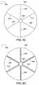
- FIG. 4Aillustrates a cell, subdivided into three sectors, surrounding a base station utilizing a sectorized antenna and operating on a first carrier frequency A.
- FIG. 4Billustrates the base station of FIG. 4A with a second sectorized antenna operating on a second carrier frequency B.
- the antenna of FIG. 4Bhas been offset 60 deg with respect to the antenna of FIG. 4A resulting in the three sectors of the cell of FIG. 4 b being offset by 60 deg with respect to the three sectors of FIG. 4A .
- FIG. 4Cis an overlay of FIGS. 4A and 4B showing the base station of FIG. 4A , simultaneously transmitting on the two carrier frequencies A and B and further illustrating that if the antennas are offset sufficiently, the sector boundary regions will not overlap.
- the implementation of FIG. 4 cthus creates multiple carrier diversity with regard to sectors in accordance with the invention.
- FIG. 4Dillustrates a more realistic representation of FIG. 4C illustrating that the frequency A and B sector boundaries will actually be sector boundary regions, but that the antenna offset can be chosen as in FIG. 4C so that the boundary regions do not overlap in accordance with the invention.
- FIG. 5illustrates a flow chart whose method may be implemented to exploit multiple carrier diversity with regard to sector boundaries in accordance with the invention.
- FIG. 6illustrates an example of an inter-carrier handoff at a single base station using multiple carriers of different power levels in accordance with the present invention.
- FIG. 7illustrates an exemplary communications system implementing multiple carrier diversity across cells and sectors in accordance with the present invention.
- FIG. 8illustrates an exemplary base station implemented in accordance with the present invention.
- FIG. 9illustrates an exemplary end node (wireless terminal, e.g., mobile node) implemented in accordance with the present invention.
- bandwidthWhen a large amount of bandwidth is allocated to a cellular system, the bandwidth is often divided into two or more portions, each of which has a distinct carrier deployed.
- the spectrum assigned to each distinct carrier deployedmay or may not be adjacent. These deployments are called multiple carrier systems.
- the bandwidth associated with each carriermay be reused in all cells.
- the current inventionis directed to methods and apparatus for improving the service at the cell boundaries and sector boundaries of a multiple carrier spread spectrum system, by creating and utilizing ‘multiple carrier diversity’ as described below.
- the systemis engineered for one carrier. If a second carrier is added, to be used by the same base station, typically, the same design parameters, e.g. power requirements, etc., are used resulting in the same coverage area for both carriers. In such a case, the two carriers will have the same general cell boundary and same cell boundary areas will occur between adjacent cells.
- the power between the multiple carriersis varied in a controlled and engineered manner, resulting in different cell boundaries of selected sizes for each carrier of a cell.
- the power applied by adjacent base stations with respect to each carrier frequencymay be varied using similar reasoning in the multiple adjacent cells of the communications system. This creates different and potentially non-overlapping boundary areas for each carrier used in a cell.
- FIGS. 2A , 2 B, 2 C, and 2 Dare used to illustrate a method of creating multiple carrier diversity, in accordance with the invention.
- an exemplary system 200includes a first base station, base station 1 (BS 1 ) 202 and a second base station, base station 2 (BS 2 ) 204 .
- BS 1 202has a nominal transmission power of a carrier with frequency A, P A1 , as represented by arrow 203 , with a cellular coverage area enclosed by solid line circle 206 .
- BS 2 204has a nominal transmission power of a carrier with frequency A, PA 2 , as represented by arrow 205 , with a cellular coverage area enclosed by solid line circle 208 .
- FIG. 2Aalso includes a carrier frequency A boundary area 210 between adjacent cell areas 206 and 208 .
- an exemplary system 220includes the two base stations, BS 1 202 and BS 2 204 , each with a nominal transmission power of a carrier with frequency B, P B,1 as indicated by arrow 223 , P B,2 , as indicated by arrow 225 , respectively, and each with a carrier frequency B cellular coverage area enclosed by dashed line circles 226 , 228 , respectively.
- Coverage area 226is larger than coverage area 228 , and may be due to a higher level of power applied at BS 1 202 than at BS 2 204 with respect to carrier with frequency B (P B1 223 >P B2 225 ).
- FIG. 2Balso includes a carrier frequency B boundary area 230 between cell areas 226 and 228 .
- both base stations 202 , 204are shown to use both carriers A and B simultaneously.
- the transmission powers P A,1 ,P B,1 ( 203 , 223 ) of the two carriers, A and B, respectively, in BS 1 202are selected to be different.
- the transmission powers P A,2 ,P B,2 ( 205 , 225 ) of the two carriers, A and B, respectively, in BS 2 204are selected to be different.
- 2Cshows that in BS 1 202 , the difference in the nominal transmission power of carrier A, P A,1 , 203 from that of carrier B is P B,1 . 223 , results in different size cellular coverage areas 206 , 226 , respectively for BS 1 202 .
- the difference in the nominal transmission power of carrier A, P A,2 , 205 from carrier B, P B,2 ., 225results in different size cellular coverage areas 208 , 228 , respectively for BS 2 204 .
- the cell boundary between adjacent cell for carrier A 210is determined by P A,1 203 and P A,2 , 205 and the cell boundary between adjacent cells for carrier B 230 is determined by P B,1 223 and P B,2 225 .
- the example of FIGS. 2A , 2 B, 2 Cshows an ideal case where the transmission powers have been matched precisely so that the A frequency boundary 210 is a single point and the B frequency boundary 230 is a single point.
- each carrier frequency boundarymay be represented by a region of overlapping coverage between the two base stations 202 , 204 .
- each carrier frequency boundary regionmay be defined as an area where the difference in carrier signal strength, for a particular carrier frequency, from the base stations 202 , 204 is 3 dB or less.
- a carrier frequency cell boundary regionmay be defined in terms of a signal difference of e.g., less than 1, 2, 4, 5 or 6 dB depending on the implementation.
- different levels of interferencemay define the carrier frequency cell boundary region.
- the exemplary system 260 of FIG. 2Dillustrates a frequency A boundary region 270 and a frequency B boundary region 280 .
- the values of those transmission powers, P A,1 203 , P A,2 205 , P B, 1 223 , and P B,2 225can chosen to be sufficiently different such that the cell boundary regions of carriers A and B ( 270 , 280 ) are sufficiently non-overlapping.
- FIGS. 2C and 2Dshow examples of cell boundaries of carriers A and B, that are apparently non-overlapping, in accordance with the invention.
- a wireless terminalmay measure the signal quality of all the carriers and select to use a proper carrier such that the wireless terminal is not in the cell boundary region of the selected carrier. For example, with respect to FIG.
- a wireless terminalmonitors signal interference associated with each of the carriers in a cell and proactively switches between them to select a carrier that is not a boundary carrier without necessarily losing contact with the base station on an existing carrier that is being used. For example, carrier switching may occur when an SNR decreases to between 6 and 0 dB and another carrier is available.
- the carrier selection processincludes selecting the non-boundary carrier, with the least interference or the least traffic loading.
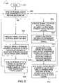
- FIG. 3illustrates a flow chart 300 whose method may be implemented by a wireless terminal to exploit the multiple carrier diversity, in accordance with the invention.
- the processstarts with step 301 where a wireless terminal is powered and able to receive base station signals.
- Operationproceeds to step 302 , where the wireless terminal measures the signal strengths; e.g. via pilot tone reception measurements, of the adjacent base stations and the serving base station in all, or a subset of all, the carriers used by the base stations.
- the wireless terminalmeasures the signal strengths; e.g. via pilot tone reception measurements, of the adjacent base stations and the serving base station in all, or a subset of all, the carriers used by the base stations.
- RFRadio Frequency
- baseband receiver chainsEach receiver chain includes a carrier filter and a demodulator arranged in series.
- Each of the receiversis capable of receiving one carrier with the filters of each chain being designed to pass the carrier frequency associated with the receiver chain while rejecting other carrier frequencies.
- the analog filter(s) used in each filter chainis adjustable and/or programmable in order to be able to lock onto a particular selected carrier.
- This first approachuses two separate processing chains, e.g., relatively expensive analog processing chains. Normally, a mobile terminal doesn't talk to two carriers simultaneously because two separate analog processing chains would be required, resulting in an expensive implementation. Thus, for cost reasons, in many cases a single receiver chain is used.
- the wireless terminalmay temporarily use its receiver to monitor other carriers when not processing the carrier currently being used to communicate with a base station.
- the analog filteris adjustable and programmable with the ability to lock onto a particular selected carrier. This is particularly possible and cost effective in a wireless data terminal, where the terminal can use the period of time during which no reception is needed from the current serving carrier to monitor other carriers.
- a third alternativeis to have a single radio frequency receiver capable of receiving signals encompassing several carriers and have base band receivers which can tune to the different carriers and measure their signal strengths.
- the analog filtering required for this methodmay also be adjustable and programmable.
- the wireless terminal in step 304identifies whether it is located in the cell boundary region of any carriers. Those carriers, identified by the wireless terminal to be in a cell boundary region, are called and classified as cell boundary carriers. This may be done by comparing pilot tone strengths and determining if pilot tones from different cells have at least a 30% difference in received power with lower power differences being interpreted, in some embodiments as an indication of a device's presence in a cell boundary region. In other embodiments a power difference of 20% or less between carrier signals from different cells is used to define boundary regions. Alternatively, an SNR of 3 dB or less may be used as indicative of being in a cell boundary region.
- the carrier selection processis performed when a decrease in the SNR is detected on the carrier being used and the SNR drops below an upper threshold, e.g., 3 dB, but still remains acceptable, e.g., above 0 dB.
- an upper thresholde.g. 3 dB
- step 306the wireless terminal determines candidate carriers.
- the candidate carriersare those carriers which have been received in step 302 and deemed to be of acceptable signal strength but excluding the cell boundary carriers identified in step 304 , e.g., carriers suffering from intercell interference of at least 30%.
- step 308the wireless terminal determines which carrier to be used, e.g. as a function of signal interference, signal quality and/or other factors.
- the wireless terminalselects from amongst the candidate carriers, if possible, and does not, if possible, select a cell boundary carrier.
- the wireless terminalmay in step 308 select a carrier as a function of other conditions or concerns such as traffic loading. Traffic loading information may be obtained, e.g., based on information available to the node such as monitored channel assignment information.
- the above carrier monitoring and selection proceduremay repeat periodically and/or frequently as implemented with operation returning to step 302 .
- FIGS. 4A , 4 B, 4 C, and 4 Dare used to illustrate another method of creating multiple carrier diversity, in accordance with the invention, in a sectorized environment.
- a base station 402uses three-sector antennas.
- FIG. 4Aillustrates an exemplary three sector cell 400 surrounding base station 402 with a coverage area 404 for a carrier of frequency A.
- the coverage area 404is broken into three sectors: S 1A 406 , S 2A 408 , and S 3A 410 with sector boundaries: sector boundary 1 - 2 412 , sector boundary 2 - 3 414 , and sector boundary 3 - 1 416 .
- FIG. 4Billustrates an exemplary three sector cell 420 surrounding base station 402 with coverage area 404 for a carrier of frequency B.
- the coverage area 404is broken into three sectors: S 1B 426 , S 2B 428 , and S 3B 430 with sector boundaries: sector boundary 1 - 2 432 , sector boundary 2 - 3 434 , and sector boundary 3 - 1 436 .
- FIG. 4Cillustrates in cell 440 (as an overlay of FIGS. 4A and 4B , an exemplary case where base station 402 has two carriers, of frequency A and B, which are to be used in all the sectors simultaneously.
- the total coverage area 404may be the same for both frequencies A and B.
- the antennas used for each frequencyare aligned so that the sectors and sector boundaries are the same for each frequency.
- the two three-sector antennasare placed such that the sectorization orientations of the two carriers at the base station 402 are sufficiently offset, e.g. 60 deg, as illustrated in FIG. 4C to provide ‘multiple carrier diversity’.
- the example of FIG. 4Cshows an offset of approximately 60 deg between the sector boundaries of the two carrier frequencies: ( 412 , 432 ), ( 414 , 434 ), ( 416 , 436 ).
- each carrier frequency sector boundary regionis defined as an area where the difference in carrier signal strength from the adjacent sector base station transmissions for a given carrier frequency is 3 dB or less.
- different levels of interferencemay define the sector carrier frequency sector boundary region, e.g., differences of 2 dB may be used in some embodiments or other values such as 1 or 4 dB.
- FIG. 4Dillustrates an exemplary cell 460 with cellular coverage area 404 for base station 402 employing a 3 sector implementation with 60 deg offsets, and simultaneous dual carrier frequency operation.
- FIG. 4Dincludes frequency A sector boundary areas: boundary region 1 - 2 462 , boundary region 2 - 3 464 , and boundary region 3 - 1 466 .
- the frequency A sector boundary regions 462 , 464 , 466may be identified by crosshatch shading in FIG. 4D .
- FIG. 4Dalso includes frequency B sector boundary areas: boundary region 1 - 2 472 , boundary region 2 - 3 474 , and boundary region 3 - 1 476 .
- the frequency B sector boundary regions 472 , 474 , 476may be identified by diagonal line shading in FIG. 4D .
- the sector boundary regions of frequency A carriers 462 , 464 , 466 and the sector boundary regions of frequency B carriers 472 , 474 , and 476are sufficiently non-overlapping, thereby creating multiple carrier diversity with regard to sectorization, similar to that shown in FIG. 2D with regard to cells.
- Wireless terminals in such a sectorized systemmay apply the same logic shown in FIG. 3 for cells, to sectors to utilize the advantages of multiple carrier diversity, in accordance with the present invention. Specifically, wireless terminals operating in an A carrier frequency boundary region 462 , 464 , 466 should and will choose to operate on carrier frequency B; while wireless terminals operating in a B carrier frequency boundary region 472 , 474 , 476 should and will choose to operate on carrier frequency A.
- Wireless terminals outside, the sector boundary regions 462 , 464 , 466 , 472 , 474 , 476 , yet still inside the cellular coverage area 404may choose to operate on either carrier frequency A or B depending on other constraints such as loading and signal interference due to conditions other than inter-cell or inter-sector interference.
- FIG. 5illustrates a flow chart 500 whose method may be implemented by a wireless terminal to exploit multiple carrier diversity with regard to sectorization, in accordance with the invention.
- the processstarts with step 501 where a wireless terminal is powered on and capable of receiving base station signal.
- Operationproceeds to step 502 where the wireless terminal measures the signal strengths of the available sector transmissions (e.g. pilots) from the serving base station for all or a subset of all the carriers.
- the available sector transmissionse.g. pilots
- the wireless terminal in step 504identifies whether it is located in the sector boundary region of any carriers. Those carriers, identified by the wireless terminal to be in a sector boundary region, are called and classified as sector boundary carriers. This determination may be basd on signal interference levels. Operation proceeds to step 506 , where the wireless terminal determines candidate carriers. The candidate carriers are those carriers which have been received in step 502 and deemed to be of acceptable signal strength excluding the sector boundary carriers identified in step 504 .
- the wireless terminaldetermines which carrier to be used. In accordance with the invention, the wireless terminal selects from amongst the candidate carriers, if possible, and does not, if possible, select any sector boundary carrier.
- the wireless terminalmay in step 508 select the carrier as a function of one or more conditions or concerns such as traffic loading.
- the above carrier monitoring and selection proceduremay repeat periodically and/or frequently as implemented with operation returning to step 502 .
- the carrier selection processoccurs even when the existing carrier remains suitable for use, e.g., has an SNR of above 0 dB.
- the carrier signalis deemed unsuitable for use when the interference signal has a power level 80% of the power level of a signal of interest.
- the selection processmay be limited to cases where a decrease in SNR below a threshed level is detected as will occur upon entry into a boundary area.
- the handoffmay further be restricted by requiring the decrease in SNR to be maintained for some predetermined period of time. Drops below a second threshold, e.g., 1 dB may trigger an immediate handoff. Given the described intercarrier handoff process, the wireless terminal may switch repeatedly between carriers while communicating with the same base station even though an existing carrier remains acceptable, e.g., above 0 dB in terms of SNR.
- operationproceeds from step 502 to step 509 , in which the wireless terminals feeds back information to the serving base station including, e.g. signal strength/quality of the received sector transmissions from the serving base station for the carriers.
- the serving base stationidentifies the sector boundary carriers for each wireless terminal.
- the serving base stationdetermines candidate carriers for each wireless terminal, which are the received carriers of step 502 of acceptable strength excluding the sector boundary carriers identified in step 510 .
- step 512the serving base station determines which carrier to be used for each wireless terminal.
- the serving base stationselects for each wireless terminal from amongst the specific wireless terminal's candidate carriers, if possible, and does not, if possible, select a sector boundary carrier.
- the serving base stationmay for each wireless terminal in step 512 select the carrier according to various conditions or concerns such as traffic loading.
- the above carrier monitoring and selection proceduremay repeat periodically and/or frequently as implemented with operation returning to step 502 .
- the same methods of creating multiple carrier diversitycan be used in a beam-forming multiple antenna system, where a different set of antenna coefficients are used for different carriers to create different carrier transmission patterns.
- the boundary areas of different carriersare generated to avoid overlapping boundary areas.
- FIGS. 2 A, 2 B, 2 C, 2 D and FIGS. 4 A, 4 B, 4 C, 4 Dcan be combined to minimize or eliminate overlapping boundary areas corresponding to different carriers.
- FIGS. 2 A, 2 B, 2 C, 2 D and 3 sectors in FIGS. 4 A, 4 B, 4 C, 4 Dthe concepts are equally applicable and may be extended to other implementation involving other numbers of cells and/or cells with other numbers of sectors.
- the two methods of creating multiple carrier diversity shown in FIGS. 2 A, 2 B, 2 C, 2 D and FIGS. 4 A, 4 B, 4 C, 4 Dcan be generalized in accordance with the invention.
- the boundary regionse.g., cell boundary, or sector boundary
- these system parametersare selected in the system design and purposely made different for different carriers such that the boundary regions of individual carriers have minimum or even zero overlap.
- the wireless terminals moving throughout the systemmay exploit the multiple carrier diversity that has been established by, identifying and excluding any boundary carriers, and then selecting to operate on another available non-boundary carrier, which has been made available by the multiple carrier diversity.
- FIG. 6 600illustrates examples of inter-carrier handoffs at a single base station 602 using multiple carriers of different power levels in accordance with the present invention.
- a cell boundary 604 for carrier frequency Arepresents the coverage area in which an exemplary wireless terminal 608 may communicate using carrier frequency A with base station 602 under ideal conditions
- a cell boundary 606 for carrier frequency Brepresents the coverage area that the exemplary wireless terminal 608 may communicate using carrier frequency B with base station 602 under ideal conditions.
- Cell boundary 612 for carrier frequency Arepresents the coverage area in which exemplary wireless terminal 608 may communicate using carrier frequency A with an adjacent base station
- a cell boundary 614represents the coverage area in which the exemplary wireless terminal 608 may communicate using carrier frequency B with the adjacent base station.
- Area 616shown with line shading ascending from left to right, represents a carrier frequency A boundary region between adjacent cells.
- Area 618shown with line shading descending from left to right, represents a carrier frequency B boundary region between adjacent cells.
- a dashed line arrow 610represents wireless terminal, e.g. mobile node, 608 crossing carrier frequency A cell boundary 604 .
- a solid line arrow 620represents wireless terminal, e.g., mobile node 608 crossing into a carrier frequency A boundary region between adjacent cells 616 .
- the transmission power levelwould be substantially equivalent for the multiple carriers used, resulting in the same cell boundaries for all carrier frequencies.
- a wireless terminalmoved throughout the cell, it would lock onto one frequency and remain on that one frequency while communicating with that base station until a hand-off occurs to another adjacent cell with a new base station or until reception is lost due to some variation such as a change of natural conditions, e.g., physical obstructions, weather conditions, etc.
- the wireless terminalproactively monitors and searches for alternative carriers and performs inter-carrier hand-offs using the same base stations as part of normal operation resulting in better traffic load balancing, increased efficiency, and an improvement in system performance.
- wireless terminal 608located within the cell boundaries for both frequencies A and B ( 604 , 606 ), respectively, may have locked onto a specific carrier, e.g. the stronger carrier frequency, B; however, the wireless terminal 608 may decide to move to another carrier, e.g. carrier frequency A, for load balancing purposes, and thus perform an inter-carrier handoff at base station 602 .
- This inter-carrier hand-offwould free up the higher power carrier frequency for use by another wireless terminal at a different location that may require increased signal strength to continue operation.
- the wireless terminal 608may be operating on the weaker carrier signal, e.g.
- wireless terminal 608may lose the one carrier, e.g. carrier frequency A, that it is using as it crosses cell boundary for carrier frequency A 604 , as illustrated by dashed arrow 610 .
- the cell boundary for carrier frequency A 604is actually an intracell carrier frequency A boundary region. In some embodiments this intracell boundary region may be defined as an area where the difference in carrier signal strength from the base station falls off to approximately 0 dB.
- different levels of signal strengthmay define the intracell carrier frequency cell boundary regions, e.g., SNR levels of 1, 2, 3, 4, 5 or 6 dB or less may, and sometimes are, used to define cell boundary regions.
- a switch to carrier frequency B, from carrier A,is used to maintain or to reestablish communications.
- the wireless terminale.g. mobile node 608 proactively monitors and searches for alternative carriers, collects data on the carriers, makes decisions on which carrier to be used within the cell and/or feeds back information to the base station 602 to decide which carrier to use with the cell. This allows the system 600 to anticipate the necessity of inter-carrier handoffs at the single base station 602 and efficiently perform the inter-carrier handoff operations before loss of communication occurs or with minimal disruption of communications between the base station 602 and the mobile 608 .
- wireless terminal 608is located within the cell boundaries for both carrier frequency A and B, ( 604 , 606 ), respectively, and is operating on carrier frequency A to communicate with base station 602 .
- Wireless terminal 608moves and crosses into the boundary region between adjacent cells for carrier frequency A 616 .
- the wireless terminal 608has been proactively searching for candidate carriers.
- the wireless terminal 608proactively switches to carrier frequency B once it detects that the current serving carrier, carrier frequency A, is becoming a boundary carrier.
- the quality of the current serving carrieris better than in traditional handoff scenarios. This results in an improved level of communications, over traditional handoff scenarios, with minimal or no disruptions in service between wireless terminal 608 and base station 602 during the handoff process.
- the multiple carrier diversityresults in an improved level of performance, over tradition handoffs, because the new operational carrier, carrier B is not a boundary carrier.
- the actual power reception levels of the wireless terminalsmay vary normally due to natural condition, e.g. obstructions, weather conditions, etc.
- Typical multi carrier implementationsuse only one power level for all the carrier frequencies at the same base station; however, the present invention uses different power levels for different carrier frequencies at the same base station. If a wireless terminal is operating on a frequency and begins to lose signal due to a natural cause, with the typical implementation the signal may be expected to have degraded equally on all the potential frequencies, and communications may be lost.
- the wireless terminal 608may select to perform an inter-carrier handoff at base station 602 to another carrier frequency, if available, that has been allocated a higher level of power transmission by the base station 602 resulting maintained communications between base station 602 and wireless terminal 608 .
- FIG. 7illustrates an exemplary communications system 700 implementing multiple carrier diversity across both cells and sectors in accordance with the present invention.
- the communications system 700includes a plurality of base stations, base station 1 702 with a coverage area defined by cell 1 701 , base station M 702 ′ with a coverage area defined by cell N 703 .
- Each base station 702 , 702 ′ of exemplary system 700may operate on two carrier frequencies A and B at different power levels, in accordance with the invention.
- the power level for carrier frequency Ais less than the power level for carrier frequency B; therefore, a cell 1 boundary for frequency A (solid line circle) 714 is smaller than a cell 1 boundary for frequency B (dashed line circle) 712 .
- Cell 1 701includes a coverage area which is the composite of the areas defined by boundaries 712 and 714 .
- the power level for carrier frequency Bis less than the power level for carrier frequency A; therefore, a cell N boundary for frequency B (dashed line circle) 734 is smaller than a cell N boundary for frequency A (solid line circle) 732 .
- Cell N 703includes a coverage area which is the composite of the areas defined by boundaries 732 and 734 .
- a carrier frequency A boundary region for cells 1 and Nis represented by the ascending line shaded area 749 ; a carrier frequency B boundary region for cells 1 and N is represented by the descending line shaded area 750 .
- the two cell boundary regions 749 and 750do not overlap by design in accordance with the invention.
- base stationsmay operate on multiple carrier frequencies at different power levels, in accordance with the invention.
- Base station 1 702may transmit to a plurality of sectors, which subdivide the cellular coverage area for cell 1 .
- Base station 1 702is configured with a plurality of multisector antennas, one for each carrier frequency used. Information on two sectors: designated sector 1 and sector Y are shown in FIG. 7 for simplicity. The base station's antennas are offset sufficiently so that the boundary regions between sectors do not overlap in accordance with the invention.
- an area with crosshatched shading 716represents the sector 1 /sector Y boundary area for carrier frequency A; an area with small circle shading 718 represents the sector 1 /sector Y boundary area for carrier frequency B.
- Area 760represents sector 1 non-boundary area for both carrier frequencies A and B.
- Area 762represents sector Y non-boundary area for frequency A and sector 1 non-boundary area for frequency B.
- Area 764represents sector Y non-boundary area for both frequencies A and B.
- Area 766represents sector 1 non-sector boundary area for frequency A and sector Y non-sector boundary area for frequency B.
- the cellular coverage area for base station M 702 ′may be subdivided into sector boundary areas: sector 1 /sector Y boundary area for frequency A 746 (horizontal line shading), sector 1 /sector Y boundary area for frequency B 748 (vertical line shading), and non-sector boundary areas: sector 1 frequencies A and B area 770 , sector 1 frequency B/sector Y frequency A area 772 , sector Y frequencies A and B area 774 , and sector 1 frequency A/sector Y frequency B area 776 .
- Base station 1 702is coupled to a plurality of end nodes (ENs), e.g. wireless terminals such as mobile nodes (MNs), fixed wireless devices, etc., in sector 1 : EN( 1 ) 704 , EN(X) 706 via wireless links 720 , 722 , respectively.
- ENsend nodes
- MNsmobile nodes
- X′end nodes
- base station 1 702is coupled to a plurality of end nodes in sector Y: EN( 1 ′) 708 , EN(X′) 710 via wireless links 724 , 726 , respectively.
- base station M 702 ′is coupled to ENs 704 ′, 706 ′, 708 ′, and 710 ′ via wireless links 720 ′, 722 ′, 724 ′, and 726 ′, respectively.
- the ENs 704 , 706 , 708 , 710 , 704 ′, 706 ′, 708 ′, and 710 ′may move throughout the system 700 , establish a communication session with a peer node, e.g., another end node, establish communication with the base stations 702 , 702 ′, and exchange data and information directly with the base stations 702 , 702 ′ over the air.
- the ENs, e.g. EN( 1 ) 704in accordance with the invention, proactively monitor signal strengths and/or quality for available carrier frequencies, identify any cell and/or sector boundary carrier frequencies, determine possible candidate carriers, and select a carrier to use to minimize any boundary problems.
- the ENscan also decide to make inter-frequency handoffs between carriers at a single base station, and may select or change carriers based on non-boundary considerations, e.g., traffic loading, in order to optimize performance.
- the base stations 702 , 702 ′are coupled to a network node 740 via network links 742 , 744 , respectively.
- the network nodemay couple the system 700 to other network nodes, e.g. other bases stations, access routers, intermediate nodes, home agent nodes, or Authentication, Authorization, Accounting (AAA) server nodes via network link 746 .
- Network links 742 , 744 , and 746may be, e.g. fiber optic cables.
- an exemplary ENfor example EN( 1 ) 704
- EN( 1 ) 704is moving throughout the area of potential coverage for communications with base station 1 702 . If EN 704 is outside boundary 714 , it will not use frequency A to communicate with BS 1 702 because of insufficient reception strength. If EN 704 is located in cellular boundary region 749 , it is restricted, from using frequency A (a cell boundary carrier) to communicate, but may use frequency B to communicate with BS 1 702 . If EN 704 is in boundary region 750 , it is restricted from using frequency B (a cell boundary carrier) to communicate, but may use frequency A to communicate with BS M 702 ′.
- frequency Aa cell boundary carrier
- EN 704is in sector boundary region 716 , it is restricted from using frequency A (a sector boundary carrier), but may use frequency B to communicate with BS 1 702 . If EN 1 704 , is in sector boundary region 718 , it is restricted from using frequency B (a sector boundary carrier) to communicate with BS 1 702 , but may use frequency A provided EN 704 is within boundary 714 . In the remaining areas of potential BS 1 702 coverage there is no restriction, and BS 1 702 may select from either frequency based on other considerations such as traffic loading.
- frequency Aa sector boundary carrier
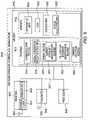
- FIG. 8illustrates an exemplary base station (BS) 800 implemented in accordance with the present invention.
- Exemplary base station 800may be a more detailed representation of base stations 202 , 204 of FIG. 2 , 402 of FIG. 4 , 602 of FIG. 6 , and 702 , 702 ′ of FIG. 7 .
- the exemplary BS 800includes a receiver circuit 802 , transmitter circuit 804 , processor 806 , e.g, CPU, memory 810 and an I/O network interface 808 coupled together by a bus 807 .
- the receiver circuit 802is coupled to one or more antennas 803 , 803 ′ for receiving signals from end nodes 900 (See FIG. 9 ), e.g., wireless terminals such as mobile nodes.
- the transmitter circuit 804is coupled to one or more transmitter antennas 805 , 805 ′ which can be used to broadcast signals to end nodes 900 .
- the transmitter circuit 804may include a plurality of sector transmitter circuits, sector 1 transmitter circuitry 840 , sector N transmitter circuitry 840 ′.
- the receiver circuit 802 and the transmitter circuit 804shall be capable of operating on a plurality of carrier frequencies.
- the transmitter 804shall operate at different power levels corresponding to different carrier frequencies in order to create distinct cell boundaries for each carrier frequency.
- the receiver circuit 802may include a de-scrambler circuit and the transmitter circuit 804 may include a scrambler circuit in various embodiments of the invention.
- the antennas 803 , 803 ′, 805 , 805 ′may be sectorized antennas in various embodiments.
- multiple transmitter antennas 805 , 805 ′may exist for each of the base station's 800 carrier frequencies, and each sectorized antenna 805 , 805 ′ may be offset by a sufficient amount to prevent or minimize sector boundary overlap regions.
- one pair of sectorized receiver/transmitter antennas 803 / 805 , 803 ′/ 805 ′may exist for each of the base station's 800 carrier frequencies; each pair of the sectorized antennas may be offset to prevent or minimize sector boundary overlap regions.
- the network I/O interface 808is used to couple the base station 800 to one or more network elements, e.g., routers and/or the Internet. In this manner, the base station 800 can serve as a communications element between end nodes 900 serviced by the base station 800 and other network elements.
- network elementse.g., routers and/or the Internet.
- Operation of the base station 800is controlled by the processor 806 under direction of one or more routines 812 stored in the memory 810 which control the basic functionality of the base station 800 and implement the various features and methods of the present invention.
- Memory 810includes routines 812 and data/information 814 .
- the routines 812include a communications routine 816 , signal generation/reception routines 818 , a scheduler 820 , a power management routine 822 , a sector management routine 824 , and an inter-carrier handoff routine 825 .
- Data/Information 814includes active user information 826 , data 828 , carrier frequency information 830 , and system parameter information 832 .
- Communications routines 816include various communications applications which may be used to provide particular services, e.g., IP telephony services or interactive gaming, to one or more end node 900 users.
- Signal generation/reception routines 818utilize the data/info 814 , e.g, data 828 , system parameter information 832 , and carrier information 830 to provide the required signal synchronization, generation, reception and processing.
- the scheduler 820may perform assignments of users (end nodes 900 ) to operate: on specific carrier frequencies, on specific channels using specific sub-carrier frequencies, within specific sectors, at specific times.
- the scheduler 820may use active user info 826 in making scheduling decisions between various end nodes 900 in order to minimize disruptions on cell/sector boundaries, more efficiently load balance the system, and satisfy the needs and requests of the various end nodes 900 .
- Power management routine 822may utilize the data/info 814 , e.g., carrier frequency information 830 and system parameter information 832 to control and regulate the different power levels that may be assigned to each carrier frequency used by the base station 800 thus creating different cell boundaries for different carrier frequencies in accordance with one embodiment of the present invention.
- Sector management routine 824may use the data/info 814 , e.g., carrier frequency information 830 to establish and control different non-overlapping sector boundaries for different carrier frequencies in accordance with one embodiment of the present invention.
- Inter-carrier handoff routine 825may utilize the data/info 814 including carrier frequency info 830 and active user information 826 to perform a hand-off operation between different carrier frequencies for a user, e.g. mobile node 900 , while still maintaining attachment to the same base station 800 , due to a request from a user triggered by items such as: the identification of a sector boundary carrier, the identification of a cell boundary carrier, a change in conditions, an attempt to better load balance the system in accordance with some embodiments of the invention.
- the decision to perform an inter-carrier hand-off operationmay be made by the base station 800 based on data/info 814 , e.g, active user information 826 , carrier information 830 , e.g., current traffic loading on each carrier, and other information available to the base station 800 .
- the inter-carrier hand-off routine 825may use feed back information from the wireless terminal 900 , e.g., active user info 826 such as intercell and/or intracell interference information to determine whether the wireless terminal 900 is in a boundary or non-boundary region.
- intra-cell and intra-sector carrier handoffsmay be initiated even though communication with a wireless terminal remains possible using a carrier already being used to communicate with the wireless terminal.
- inter-carrier hand-off routine 825may make decisions and perform carrier handoff operations as a function of other system consideration such as loading. In some cases, system loading as opposed to interference considerations will trigger an intra-cell and/or intra sector carrier handoff.
- Active user information 826includes information for each active user and/or end node 900 serviced by the base station 800 .
- the user information 834 , 834 ′includes, state information, e.g., whether the mobile node 900 is in an on state, a hold state, a sleep state, or an access state, number and types of data packets currently available for transmission to or from the end node 900 , assigned carrier frequency, assigned sector, and information on the communication resources used by the end node 900 .
- the user information 834 , 834 ′may also include information feed back from the end node 900 such as received pilot signal strength, recognized boundary carriers, requested carrier hand-offs, channel quality information, intercell interference information, and intracell interference information.
- Data 828may include data to be transmitted to, or received from, one or more end nodes 900 . Examples of data 828 may include, e.g., voice data, E-mail messages, video images, game data, etc.
- Carrier frequency information 830may include the carrier frequencies assigned to the base station 800 and associated information such as corresponding power level assignments, actual operational power levels, traffic loading, corresponding sector assignments, sector traffic loading for each carrier frequency and sector specific parameters such as e.g.
- System parameter information 832may include, e.g., transmitted pilot power levels, data/control and pilot hopping sequence values for the cell and sectors of the base station 800 .
- FIG. 9illustrates an exemplary end node 900 implemented in accordance with the invention.
- Exemplary end node 900may be a wireless terminal, e.g., mobile node or stationary wireless communications device.
- End node 900may be a more detailed representation of the wireless terminal previously described with respect to the invention in FIGS. 2-8 such as EN 608 of FIG. 6 or EN( 1 ) 704 of FIG. 7 .
- the exemplary end node 900includes a receiver 902 coupled to an antenna 903 , a transmitter 904 , coupled to an antenna 905 , a memory 910 and a processor 906 .
- the receiver 902in the illustrated embodiment includes a single receiver chain including a channel filter 951 and demodulator 952 .
- multiple receiver chainsare used to allow for multiple carriers to be received and processed at the same time.
- Channel filter 951is adjustable so that the passband of the filter can be selected to correspond to the carrier being received at any point in time.
- the various elements of the end node 900receiver 902 , transmitter 904 , processor 906 , and memory 910 are coupled together via bus 907 .
- the end node 900uses its transmitter 904 , receiver 902 , and antennas 905 , 903 to send and receive information to and from base station 800 .
- the transmitter 904 and receiver 902shall be capable of operating on multiple carrier frequencies as utilized by the various base stations 800 .
- the transmitter 904 and the receiver 902may include encoder/decoder circuits to match the base stations 800 .
- the receiver 902 and/or the transmitter 904shall have programmable analog filters to allow a single analog circuit path to be utilized for multiple carrier frequencies thus reducing cost.
- Various embodiments of the receiver 902are possible as previously described with respect to FIG. 3 including: two RF and baseband receiver chains where one chain is tuned to a particular carrier and the other chain searches for alternative carriers, one RF and baseband receiver chain where the receiver 902 uses the times during which no reception is required from the current serving carrier to monitor other alternative carriers, and a single RF receiver capable of receiving signals encompassing several carriers and have baseband receiver which can tune to different carriers and measure their signal strength.
- Memory 910includes routines 912 and data/info 914 .
- the routines 912may include a communications routine 916 , signal generation/reception routines 918 , a transmission power control and power control signaling routine 950 including a carrier strength measurement routine 920 , a cell/sector boundary identification routine 922 , and a carrier selection routine 924 .
- the data/info 914may include user/device information 926 , data 928 , carrier information 930 , and system parameter information 932 .
- the end node 900operates under control of the modules or routines 912 , which are executed by the processor 906 in order to perform the basic functionality of the end node 900 and implement the methods and improvements in accordance with the present invention.
- User/device information 926includes device information, e.g., a device identifier, a network address or a telephone number. This information can be used, by the base station 800 , to identify the end nodes 900 , e.g., when assigning communications channels.
- the user/device information 926includes information concerning the present state of the end node 900 , e.g., whether the mobile node 900 is in an on state, a hold state, a sleep state, or an access state, number and types of data packets currently available for transmission to or from the base station 800 , levels of overall interference, intercell interference for each carrier, intersector interference for each carrier.
- the data 928includes, e.g., voice, text and/or other data received from, or to be transmitted to, the base station 800 as part of a communications session.
- Carrier information 930may include information such as carrier measured pilot strength levels for detected carrier frequencies, active list of candidate carriers, intercell channel interference, intersector channel interference, active list of identified cell/sector boundary carriers, active carrier, requested new carrier, etc.
- System parameter information 932may include information such as carrier frequency assignments to specific cells/base stations and/or sectors, hopping sequence parameters, coding sequences used, classifications of types of interference, and criteria levels used for classification of a carrier as a cell/sector boundary carrier, and criteria used for initiating an intercarrier handoff.
- Communications routines 916include various communications applications which may be used to provide particular services, e.g., IP telephony services or interactive gaming, to one or more end node users.
- Signal generation/reception routines 918utilize the data/info 914 , e.g, data 928 , system parameter information 932 such as hopping sequence values, user device info 926 such as device ID, carrier information 930 such as the current active carrier to provide the required signal timing control, synchronization, and signal generation and signal reception.
- the signal generation/reception routine 918controls the transmission and the reception of payload data, e.g., a channel or time slot dedicated to the end node 900 for signaling purposes.
- Routine 918may also control the operation of receiver 902 and the transmitter 904 including the setting of the programmable analog filters to the selected carrier frequencies.
- Transmission power control and power control signaling routine 950is used to control the generation, processing and reception of transmission power control signals.
- Module 950controls the signaling used to implement transmission power control through interaction with the base station 800 . Signals transmitted to, or received from the base station 800 are used to control end node 900 transmission power levels under direction of module 950 .
- Power controlis used by the base station 800 and the end nodes 900 to regulate power output when transmitting signals.
- the base station 800transmits signals to the end nodes 900 which are used by the end nodes 900 in adjusting their transmission power output.
- the optimal level of power used to transmit signalsvaries with several factors including transmission burst rate, channel conditions and distance from the base station 800 , e.g., the closer the end node 900 is to the base station 800 , the less power the mobile node 900 needs to use to transmit signals to the base station 800 .
- Using a maximum power output for all transmissionshas disadvantages, e.g., the end node 900 battery life is reduced, and high power output increases the potential of the transmitted signals causing interference, e.g., with transmissions in neighboring or overlapping cells and or sectors.
- Transmission power control signalingallows the end node 900 to reduce and/or minimize transmission output power and thereby extend battery life.
- Carrier signal strength measuring routine 920included in power routine 950 , monitors the signal strengths, e.g. pilots, and/or quality for all the carriers received by the end node 900 periodically and/or repetitively and stores the information as part of the carrier information 930 to be used by the cell/sector boundary identification routine 922 and the carrier selection routine 924 in accordance with the invention.
- Routine 920may use the user/device info 926 , e.g. state, to determine when to switch the receiver 902 to search for alternative carriers.
- Routine 920may also control the switching within the receiver 902 between different programmable filters values for different carrier frequencies as the receiver 902 searches for all carriers.
- the carrier signal strength monitoring routine 920is performed by end node 900 in a proactive manner; this allows transitions between carriers as the level of interference increases or the signal strength begins to degrade allowing the end node 900 to transition to a new carrier with minimal or no disruption in communications.
- the cell boundary/sector boundary identification routine 922identifies cell and sector boundary carriers utilizing, e.g., the carrier strength measurement information collected and applying rejection criteria defined in the system parameter info 932 .
- the cell/sector boundary identification routine 922estimates intercell channel interference due to transmissions from the base stations.
- the cell/sector boundary identification routine 922estimates intersector channel interference due to transmissions from various sector of the same base station.
- Routine 924generates a list of candidate carriers (part of carrier info 930 ) by applying an acceptable criteria, e.g., a signal strength criteria (part of system parameter info 932 ), to the list of measured carriers excluding identified cell/sector boundary carriers.
- Carrier signal strength routine 920 and cell/boundary identification routine 922may allow wireless terminal 900 to distinguish between intracell interference and other types of interference. Routines 920 and 922 may also allow wireless terminal 900 to distinguish between intersector interference and other types of interference.
- Carrier selection routine 924utilizes the list of candidate carriers to select a carrier for the end node 900 to use.
- the carrier selection routine 924may apply additional criteria, such as system traffic loading, power considerations, anticipated entry into a sector/cell boundary region to select which carrier to use.
- the present inventionmay be implemented in hardware, software, or a combination of hardware and software.
- some aspects of the inventionmay be implemented as processor executed program instructions.
- some aspects of the present inventionmay be implemented as integrated circuits, such as, for example, ASICs.
Landscapes
- Engineering & Computer Science (AREA)
- Computer Networks & Wireless Communication (AREA)
- Signal Processing (AREA)
- Mobile Radio Communication Systems (AREA)
Abstract
Description
Claims (42)
Priority Applications (3)
| Application Number | Priority Date | Filing Date | Title |
|---|---|---|---|
| US10/636,516US7363039B2 (en) | 2002-08-08 | 2003-08-07 | Method of creating and utilizing diversity in multiple carrier communication system |
| US12/060,249US8374613B2 (en) | 2002-08-08 | 2008-03-31 | Method of creating and utilizing diversity in a multiple carrier communication system |
| US13/764,230US9277470B2 (en) | 2002-08-08 | 2013-02-11 | Method of creating and utilizing diversity in a multiple carrier communication system |
Applications Claiming Priority (3)
| Application Number | Priority Date | Filing Date | Title |
|---|---|---|---|
| US40192002P | 2002-08-08 | 2002-08-08 | |
| US10/324,194US6788963B2 (en) | 2002-08-08 | 2002-12-20 | Methods and apparatus for operating mobile nodes in multiple a states |
| US10/636,516US7363039B2 (en) | 2002-08-08 | 2003-08-07 | Method of creating and utilizing diversity in multiple carrier communication system |
Related Parent Applications (2)
| Application Number | Title | Priority Date | Filing Date |
|---|---|---|---|
| US10/324,194Continuation-In-PartUS6788963B2 (en) | 2002-08-08 | 2002-12-20 | Methods and apparatus for operating mobile nodes in multiple a states |
| US10/324,194ContinuationUS6788963B2 (en) | 2002-08-08 | 2002-12-20 | Methods and apparatus for operating mobile nodes in multiple a states |
Related Child Applications (1)
| Application Number | Title | Priority Date | Filing Date |
|---|---|---|---|
| US12/060,249DivisionUS8374613B2 (en) | 2002-08-08 | 2008-03-31 | Method of creating and utilizing diversity in a multiple carrier communication system |
Publications (2)
| Publication Number | Publication Date |
|---|---|
| US20040106412A1 US20040106412A1 (en) | 2004-06-03 |
| US7363039B2true US7363039B2 (en) | 2008-04-22 |
Family
ID=46123471
Family Applications (3)
| Application Number | Title | Priority Date | Filing Date |
|---|---|---|---|
| US10/636,516Expired - LifetimeUS7363039B2 (en) | 2002-08-08 | 2003-08-07 | Method of creating and utilizing diversity in multiple carrier communication system |
| US12/060,249Expired - LifetimeUS8374613B2 (en) | 2002-08-08 | 2008-03-31 | Method of creating and utilizing diversity in a multiple carrier communication system |
| US13/764,230Expired - Fee RelatedUS9277470B2 (en) | 2002-08-08 | 2013-02-11 | Method of creating and utilizing diversity in a multiple carrier communication system |
Family Applications After (2)
| Application Number | Title | Priority Date | Filing Date |
|---|---|---|---|
| US12/060,249Expired - LifetimeUS8374613B2 (en) | 2002-08-08 | 2008-03-31 | Method of creating and utilizing diversity in a multiple carrier communication system |
| US13/764,230Expired - Fee RelatedUS9277470B2 (en) | 2002-08-08 | 2013-02-11 | Method of creating and utilizing diversity in a multiple carrier communication system |
Country Status (1)
| Country | Link |
|---|---|
| US (3) | US7363039B2 (en) |
Cited By (44)
| Publication number | Priority date | Publication date | Assignee | Title |
|---|---|---|---|---|
| US20040162097A1 (en)* | 2003-02-18 | 2004-08-19 | Rajiv Vijayan | Peak-to-average power ratio management for multi-carrier modulation in wireless communication systems |
| US20060050725A1 (en)* | 2004-09-09 | 2006-03-09 | Rodrigo Miguel D V | Least used channel wavelength scheduling in APSON |
| US20060052108A1 (en)* | 2003-10-16 | 2006-03-09 | Rajiv Laroia | Methods and apparatus of improving inter-sector and/or inter-cell handoffs in a multi-carrier wireless communications system |
| US20060063530A1 (en)* | 2004-09-08 | 2006-03-23 | Spreadtrum Communications Corporation | Method for cell locking in a wireless communication device |
| US20060203713A1 (en)* | 2003-05-16 | 2006-09-14 | Rajiv Laroia | Efficient signal transmission methods and apparatus using a shared transmission resource |
| US20060209721A1 (en)* | 2005-03-15 | 2006-09-21 | Qualcomm Incorporated | Interference control in a wireless communication system |
| US20060285503A1 (en)* | 2005-03-15 | 2006-12-21 | Murat Mese | Interference control in a wireless communication system |
| US20070066234A1 (en)* | 2003-07-03 | 2007-03-22 | Rotani, Inc. | Method and apparatus for high throughput multiple radio sectorized wireless cell |
| US20070070953A1 (en)* | 2005-09-28 | 2007-03-29 | Lg Electronics Inc. | Method of cooperatively relaying data in cellular networks for a broadcast multicast services |
| US20070097931A1 (en)* | 2005-10-27 | 2007-05-03 | Parekh Nileshkumar J | Tune-away and cross paging systems and methods |
| US20070097922A1 (en)* | 2005-10-27 | 2007-05-03 | Qualcomm Incorporated | Tune-away protocols for wireless systems |
| US20070099619A1 (en)* | 2005-10-27 | 2007-05-03 | Qualcomm Incorporated | Inter-frequency handoff |
| US20070099614A1 (en)* | 2005-10-27 | 2007-05-03 | Qualcomm Incorporated | Resource allocation during tune-away |
| US20070105583A1 (en)* | 2005-11-04 | 2007-05-10 | Alcatel | Method for automatic resource restriction distribution, a base station, a mobile terminal, a resource distribution device and a mobile network therefor |
| US20070270153A1 (en)* | 2004-02-05 | 2007-11-22 | Roberto Lanzo | Method and System for Radio Coverage Planning With Multiple Resolution Profile Approach |
| US20070270100A1 (en)* | 2005-10-27 | 2007-11-22 | Avneesh Agrawal | Method and apparatus for estimating reverse link loading in a wireless communication system |
| US20070281706A1 (en)* | 2004-02-05 | 2007-12-06 | Loris Stola | Method And System For Radio Coverage Planning With Local Double Grid Approach |
| US20080117849A1 (en)* | 2006-09-08 | 2008-05-22 | Qualcomm Incorporated | Method and apparatus for interaction of fast other sector interference (osi) with slow osi |
| US20080182580A1 (en)* | 2002-08-08 | 2008-07-31 | Qualcomm Incorporated | Method of creating and utilizing diversity in a multiple carrier communciation system |
| US20080299978A1 (en)* | 2007-06-01 | 2008-12-04 | Benco David S | Extending RF coverage areas for cellular telephones using base stations with ultra-wide band signaling |
| US20090042571A1 (en)* | 2005-04-18 | 2009-02-12 | Hiroyuki Ishii | Mobile station and feedback information generating method |
| US7522917B1 (en)* | 2005-09-09 | 2009-04-21 | Agilent Technologies, Inc. | System and method for visualization of connectivity relationships in a wireless system |
| US20090122736A1 (en)* | 2007-01-11 | 2009-05-14 | Qualcomm Incorporated | Using dtx and drx in a wireless communication system |
| US20090274120A1 (en)* | 2008-05-05 | 2009-11-05 | Industrial Technology Research Institute | System and method for multicarrier uplink control |
| US20090296662A1 (en)* | 2003-02-19 | 2009-12-03 | Qualcomm Incorporated | Controlled superposition coding in multi-user communication systems |
| CN101610540A (en)* | 2008-06-18 | 2009-12-23 | 阿尔卡特朗讯公司 | The control of Microcell power |
| US20100130220A1 (en)* | 2002-08-08 | 2010-05-27 | Qualcomm Incorporated | Wireless timing and power control |
| US20100227615A1 (en)* | 2003-12-11 | 2010-09-09 | Qualcomm Incorporated | Conveying sector load information to mobile stations |
| US20100265927A1 (en)* | 2009-04-21 | 2010-10-21 | Crestcom, Inc. | Efficient Allocation of Power to Bandwidth In a Multi-Carrier Cellular Communication System |
| US20100265913A1 (en)* | 2009-04-17 | 2010-10-21 | Qualcomm Incorporated | Inter-frequency indication of association data for multi-carrier wireless deployments |
| US20120051309A1 (en)* | 2009-04-28 | 2012-03-01 | Electronics And Telecommunications Research Institute | Device, method for managing carrier of base station, terminal and method for managing carrier thereof |
| US8315662B2 (en) | 2003-08-13 | 2012-11-20 | Qualcomm Incorporated | User specific downlink power control channel Q-bit |
| US20130044731A1 (en)* | 2011-08-15 | 2013-02-21 | Qualcomm Incorporated | Proactive Feedback Transmissions During Handover Procedures |
| US8489137B1 (en)* | 2008-08-05 | 2013-07-16 | Clearwire Ip Holdings Llc | Interference mitigation |
| US20130237262A1 (en)* | 2006-09-08 | 2013-09-12 | Qualcomm Incorporated | Method and apparatus for adjustments for delta-based power control in wireless communication systems |
| US8868093B1 (en)* | 2012-06-05 | 2014-10-21 | Sprint Communications Company L.P. | Carrier frequency assignment based on transmit power differentials |
| US8868132B1 (en)* | 2005-01-07 | 2014-10-21 | Zte (Usa) Inc. | Techniques for providing efficient transmit diversity and bandwidth segmentation in a wireless communication system |
| US9167466B2 (en) | 2012-09-06 | 2015-10-20 | Apple Inc. | Enhanced measurement reporting to improve throughput when using multicarrier cells |
| US10631310B2 (en)* | 2015-03-31 | 2020-04-21 | Xi'an Zhongxing New Software Co., Ltd | Method and device for transmitting or receiving scheduling information |
| US10728714B2 (en) | 2016-03-31 | 2020-07-28 | British Telecommunications Public Limited Company | Mobile communications network |
| US11234240B2 (en) | 2018-06-08 | 2022-01-25 | British Telecommunications Public Limited Company | Wireless telecommunications network |
| US11477700B2 (en) | 2016-03-31 | 2022-10-18 | British Telecommunications Public Limited Company | Mobile communications network |
| US11510116B2 (en) | 2016-06-29 | 2022-11-22 | British Telecommunications Public Limited Company | Multicast-broadcast mobile communications network |
| US11589269B2 (en) | 2016-03-31 | 2023-02-21 | British Telecommunications Public Limited Company | Mobile communications network |
Families Citing this family (115)
| Publication number | Priority date | Publication date | Assignee | Title |
|---|---|---|---|---|
| US7035661B1 (en)* | 1996-10-11 | 2006-04-25 | Arraycomm, Llc. | Power control with signal quality estimation for smart antenna communication systems |
| US7388845B2 (en)* | 2002-08-26 | 2008-06-17 | Qualcomm Incorporated | Multiple access wireless communications system using a multisector configuration |
| US7366200B2 (en)* | 2002-08-26 | 2008-04-29 | Qualcomm Incorporated | Beacon signaling in a wireless system |
| US7272400B1 (en)* | 2003-12-19 | 2007-09-18 | Core Mobility, Inc. | Load balancing between users of a wireless base station |
| US20050207441A1 (en)* | 2004-03-22 | 2005-09-22 | Onggosanusi Eko N | Packet transmission scheduling in a multi-carrier communications system |
| JP4012167B2 (en)* | 2004-03-31 | 2007-11-21 | 株式会社東芝 | Wireless communication system |
| JP4302578B2 (en)* | 2004-06-01 | 2009-07-29 | 富士通株式会社 | Mobile communication system |
| US7400860B2 (en) | 2004-06-15 | 2008-07-15 | Rotani, Inc. | Method and apparatus for increasing data throughput |
| US7349701B2 (en)* | 2004-06-15 | 2008-03-25 | Rotani, Inc. | Method and apparatus for creating shape antenna radiation patterns |
| WO2006034401A2 (en)* | 2004-09-23 | 2006-03-30 | The Regents Of The University Of California | Multiple sub-carrier selection diversity architecture and method for wireless ofdm |
| CN101099311B (en)* | 2005-01-13 | 2012-12-19 | 富士通株式会社 | Wireless communication system and method |
| JPWO2006077696A1 (en)* | 2005-01-18 | 2008-06-19 | シャープ株式会社 | Wireless communication device, portable terminal, and wireless communication method |
| US7489282B2 (en)* | 2005-01-21 | 2009-02-10 | Rotani, Inc. | Method and apparatus for an antenna module |
| EP1859541A1 (en)* | 2005-03-08 | 2007-11-28 | QUALCOMM Flarion Technologies, Inc. | Methods and apparatus for efficient digital broadcast signaling in a wireless communications system |
| US7668530B2 (en) | 2005-04-01 | 2010-02-23 | Adaptix, Inc. | Systems and methods for coordinating the coverage and capacity of a wireless base station |
| US8233554B2 (en)* | 2010-03-29 | 2012-07-31 | Eices Research, Inc. | Increased capacity communications for OFDM-based wireless communications systems/methods/devices |
| US9258102B2 (en)* | 2005-08-23 | 2016-02-09 | Microsoft Technology Licensing, Llc | Methods and systems to mitigate inter-cell interference |
| US20070086406A1 (en)* | 2005-10-03 | 2007-04-19 | Texas Instruments Incorporated | Methods for Assigning Resources in a Communication System |
| JP2007221380A (en)* | 2006-02-15 | 2007-08-30 | Ntt Docomo Inc | Mobile station, base station and cell selection method |
| JP4726652B2 (en)* | 2006-02-27 | 2011-07-20 | 株式会社エヌ・ティ・ティ・ドコモ | Base station and handover control method |
| EP2461491A1 (en)* | 2006-02-28 | 2012-06-06 | Rotani Inc. | Methods and apparatus for overlapping MIMO antenna physical sectors |
| GB2437128B (en)* | 2006-04-12 | 2008-07-23 | Siemens Ag | A Method Of Operation In A Dual Carrier Communication System |
| US8351405B2 (en)* | 2006-07-14 | 2013-01-08 | Qualcomm Incorporated | Method and apparatus for signaling beacons in a communication system |
| US7751858B2 (en)* | 2006-05-05 | 2010-07-06 | Intel Corporation | Sleep-mode statistics apparatus, systems, and methods |
| US20080049675A1 (en)* | 2006-08-23 | 2008-02-28 | Motorola, Inc. | Method and system for hand-off based on network load |
| CN101513110B (en)* | 2006-09-01 | 2011-03-30 | 三菱电机株式会社 | Wireless communication system and wireless communication method |
| US7853282B2 (en)* | 2006-09-14 | 2010-12-14 | Qualcomm Incorporated | Power allocation in a wireless communication system |
| US7826863B2 (en)* | 2006-09-14 | 2010-11-02 | Qualcomm Incorporated | Power allocation in a wireless communication system |
| US8219092B2 (en)* | 2006-10-02 | 2012-07-10 | Freescale Semiconductor, Inc. | User equipment frequency allocation methods and apparatus |
| US20080108367A1 (en)* | 2006-11-08 | 2008-05-08 | Nextel Communications, Inc. | System and method for supporting multiple technologies in a wireless communication cell |
| KR100950655B1 (en)* | 2006-12-20 | 2010-04-01 | 삼성전자주식회사 | Method and apparatus for receiving data using multiple antennas in communication system |
| KR100856520B1 (en)* | 2007-02-21 | 2008-09-04 | 삼성전자주식회사 | SYSTEM AND METHOD FOR HAND-OVER EXECUTION WiMAX MOBILE COMMUNICATION |
| US20080268833A1 (en)* | 2007-03-30 | 2008-10-30 | Leping Huang | System and Method for Self-Optimization of Interference Coordination in Communication Systems |
| US8036702B2 (en)* | 2007-05-14 | 2011-10-11 | Intel Corporation | Method and apparatus for multicarrier communication in wireless systems |
| US8295231B2 (en)* | 2007-06-28 | 2012-10-23 | Alcatel Lucent | Method of dynamic resource allocations in wireless systems |
| US20090047931A1 (en)* | 2007-08-17 | 2009-02-19 | Qualcomm Incorporated | Method and apparatus for wireless access control |
| US8160602B2 (en)* | 2007-11-20 | 2012-04-17 | Qualcomm Incorporated | Opportunistic uplink scheduling |
| US8547857B2 (en)* | 2007-11-20 | 2013-10-01 | Qualcomm Incorporated | Opportunistic uplink scheduling |
| US8160007B2 (en) | 2007-11-20 | 2012-04-17 | Qualcomm Incorporated | Opportunistic uplink scheduling |
| US8411646B2 (en)* | 2007-11-20 | 2013-04-02 | Qualcomm Incorporated | Opportunistic uplink scheduling |
| US8515425B2 (en)* | 2007-12-19 | 2013-08-20 | Alcatel Lucent | Uplink carrier handoff and method for path loss based triggering of uplink carrier handoff |
| US8477737B2 (en)* | 2008-03-26 | 2013-07-02 | Alcatel Lucent | System and method to improve uplink coverage in multi-carrier systems |
| US8594576B2 (en)* | 2008-03-28 | 2013-11-26 | Qualcomm Incorporated | Short-term interference mitigation in an asynchronous wireless network |
| US9668265B2 (en)* | 2008-03-28 | 2017-05-30 | Qualcomm Inc. | Technique for mitigating interference in a celllar wireless communication netwok |
| AU2014202659B2 (en)* | 2008-06-27 | 2016-05-12 | Qualcomm Incorporated | Interference mitigation by transmitting on a second, lower, power level |
| US8761824B2 (en)* | 2008-06-27 | 2014-06-24 | Qualcomm Incorporated | Multi-carrier operation in a wireless communication network |
| CN102084694B (en)* | 2008-07-02 | 2014-01-22 | 贝莱尔网络公司 | High performance mobile network with automatic configuration |
| CN102239717A (en)* | 2008-10-28 | 2011-11-09 | 新加坡科技研究局 | A method of optimising bandwidth allocation in a wireless communication network |
| US8606289B2 (en)* | 2008-11-10 | 2013-12-10 | Qualcomm Incorporated | Power headroom-sensitive scheduling |
| WO2010061504A1 (en)* | 2008-11-26 | 2010-06-03 | 日本電気株式会社 | Base station, method for controlling transmitting power of base station, processor, storage medium having program stored therein, and communication system |
| WO2010061503A1 (en)* | 2008-11-28 | 2010-06-03 | 日本電気株式会社 | Base station device, method for controlling base station device, communication system, and storage medium having program stored therein |
| US20130153298A1 (en)* | 2009-02-19 | 2013-06-20 | Interdigital Patent Holdings, Inc. | Method and apparatus for enhancing cell-edge user performance and signaling radio link failure conditions via downlink cooperative component carriers |
| US8780689B2 (en)* | 2009-03-03 | 2014-07-15 | Qualcomm Incorporated | Method and system for reducing feedback information in multicarrier-based communication systems based on tiers |
| US8908595B2 (en)* | 2009-03-12 | 2014-12-09 | Qualcomm Incorporated | Methods and apparatus for adjacent channel interference mitigation in access point base stations |
| JP5222793B2 (en)* | 2009-06-05 | 2013-06-26 | 株式会社日立製作所 | Wireless communication system, base station and terminal |
| US9036572B2 (en)* | 2009-06-11 | 2015-05-19 | Lg Electronics Inc. | Measurement reporting method and device in a wireless communication system |
| EP2449684B1 (en)* | 2009-07-02 | 2014-11-19 | Telefonaktiebolaget L M Ericsson (PUBL) | Multicarrier radio receiver and method for receiving multiple carriers |
| EP2285036A1 (en)* | 2009-08-12 | 2011-02-16 | Alcatel Lucent | Method of reporting scheduling information |
| CN102025702B (en)* | 2009-09-17 | 2014-11-05 | 中兴通讯股份有限公司 | Network based on identity and position separation frame, and backbone network and network element thereof |
| KR20110060550A (en)* | 2009-11-30 | 2011-06-08 | 삼성전자주식회사 | Apparatus and method for handover of a terminal in a wireless communication system |
| US8923877B2 (en)* | 2009-12-08 | 2014-12-30 | Verizon Patent And Licensing Inc. | Method and apparatus for providing carrier adjustment to mitigate interference |
| CN102123479B (en) | 2010-01-08 | 2015-09-16 | 索尼公司 | Communication system supporting carrier aggregation and method and device for updating system information thereof |
| CN102754496A (en) | 2010-02-12 | 2012-10-24 | 交互数字专利控股公司 | Method and apparatus for enhancing cell edge user performance and signaling radio link failures via downlink coordinated component carrier signaling |
| KR101676013B1 (en)* | 2010-05-03 | 2016-11-14 | 삼성전자주식회사 | Methdo and apparatus of control channel reconfiguration in a wireless communication system |
| CN102378189B (en)* | 2010-08-12 | 2015-06-17 | 鼎桥通信技术有限公司 | Method, equipment and system for switching user equipment between master carrier and slave carrier in cell |
| EP2437529B1 (en) | 2010-10-01 | 2013-01-09 | Telefonaktiebolaget LM Ericsson (publ) | Technique for managing measurements for multiple subscriptions in a mobile terminal |
| GB2484287A (en)* | 2010-10-04 | 2012-04-11 | Vodafone Ip Licensing Ltd | Selecting base station radio systems for receiving and combining OFDM signals from a mobile station |
| AU2011334950B9 (en)* | 2010-11-30 | 2015-09-24 | Blackberry Limited | Cell re-selection in a cellular telecommunications network |
| WO2012077974A2 (en)* | 2010-12-07 | 2012-06-14 | 엘지전자 주식회사 | Method for controlling inter-cell interference in a wireless communication system that supports a plurality of component carriers, and base station apparatus for same |
| US9257842B2 (en) | 2011-02-22 | 2016-02-09 | Asoka Usa Corporation | Set-top-box having a built-in master node that provides an external interface for communication and control in a power-line-based residential communication system |
| US9736789B2 (en) | 2011-02-22 | 2017-08-15 | Asoka Usa Corporation | Power line communication-based local hotspot with wireless power control capability |
| JP2013048370A (en)* | 2011-08-29 | 2013-03-07 | Fujitsu Ltd | Mobile terminal and sleep control method thereof |
| US9369915B2 (en)* | 2011-09-28 | 2016-06-14 | Nokia Solutions And Networks Oy | Inter-system interference in communications |
| US10264478B2 (en)* | 2011-12-16 | 2019-04-16 | Samsung Electronics Co., Ltd. | Methods and apparatus to enhance reliability in millimeter wave wideband communications |
| US9485737B2 (en)* | 2011-12-26 | 2016-11-01 | Kt Corporation | Controlling radio units to transmitting signal with different transmission power |
| US9357505B2 (en) | 2011-12-26 | 2016-05-31 | Kt Corporation | Processing digital signal |
| US20130244666A1 (en)* | 2012-03-19 | 2013-09-19 | Broadcom Corporation | Power Savings in a Mobile Communications Device Through Dynamic Control of Processed Bandwidth |
| KR20130120296A (en)* | 2012-04-25 | 2013-11-04 | 한국전자통신연구원 | Multi-carrier transmitting apparatus and method for multicast service |
| US8929934B2 (en)* | 2012-04-25 | 2015-01-06 | Intel Mobile Communications GmbH | Communication devices and methods for operating a communication device |
| US10616827B2 (en) | 2012-07-10 | 2020-04-07 | Huawei Technologies Co., Ltd. | System and method for dynamically configurable air interfaces |
| JP5773961B2 (en)* | 2012-08-30 | 2015-09-02 | 京セラ株式会社 | Portable electronic devices |
| GB2505900B (en)* | 2012-09-13 | 2015-03-04 | Broadcom Corp | Methods, apparatus and computer programs for operating a wireless communications device |
| KR101465245B1 (en)* | 2012-11-12 | 2014-11-26 | 주식회사 케이티 | Signal processing system, digital signal processing apparatus and method for controlling transmitting power in the same |
| US9301307B1 (en) | 2012-12-07 | 2016-03-29 | Sprint Spectrum L.P. | Frequency band selection in a multiband communication system |
| US20160183261A1 (en)* | 2013-04-16 | 2016-06-23 | Telefonaktiebolaget L M Ericsson (Publ) | Method and radio node for transmitting downlink signals |
| GB2517217B (en)* | 2013-08-16 | 2018-03-21 | Analog Devices Global | Communication unit, integrated circuit and method for generating a plurality of sectored beams |
| GB2517218B (en) | 2013-08-16 | 2017-10-04 | Analog Devices Global | Communication unit and method of antenna array calibration |
| US9215596B2 (en)* | 2013-09-04 | 2015-12-15 | Qualcomm Incorporated | Method and apparatus for estimating a region of coverage for a sparse network almanac |
| WO2015046782A1 (en)* | 2013-09-24 | 2015-04-02 | Lg Electronics Inc. | Mac layer communication for parallel random access procedures of dual connectivity |
| US9532280B2 (en)* | 2013-11-05 | 2016-12-27 | Samsung Electronics Co., Ltd. | Electronic system with search mechanism and method of operation thereof |
| US9781685B2 (en)* | 2013-11-21 | 2017-10-03 | At&T Intellectual Property I, L.P. | Self-adaptive coverage of wireless networks |
| KR102273878B1 (en)* | 2014-07-02 | 2021-07-06 | 삼성전자 주식회사 | Method and apparatus for load balancing inter cell in wireless communication system |
| US10327156B2 (en)* | 2014-07-15 | 2019-06-18 | Lg Electronics Inc. | Resource allocation method and signal processing method of terminal |
| US20170019226A1 (en)* | 2015-07-14 | 2017-01-19 | Qualcomm Incorporated | Preamble Detection on a Communication Channel |
| US9699699B1 (en)* | 2015-11-12 | 2017-07-04 | Sprint Spectrum L.P. | Consideration of carrier characteristics when providing carrier aggregation service |
| WO2017108487A1 (en)* | 2015-12-21 | 2017-06-29 | Sony Corporation | Telecommunications apparatus and methods |
| CN108781393B (en) | 2016-03-02 | 2021-04-20 | 霍尼韦尔国际公司 | Enhanced VHF link communication method |
| US10085206B2 (en)* | 2016-03-08 | 2018-09-25 | Wipro Limited | Methods and systems for optimization of cell selection in TD-SCDMA networks |
| WO2017182050A1 (en) | 2016-04-18 | 2017-10-26 | Telefonaktiebolaget Lm Ericsson (Publ) | Dual carrier modulation with single carrier reception |
| JP2019110356A (en)* | 2016-04-26 | 2019-07-04 | シャープ株式会社 | Terminal device, communication method, and integrated circuit |
| WO2018024395A1 (en) | 2016-08-04 | 2018-02-08 | British Telecommunications Public Limited Company | Mobile communications network |
| US9769773B1 (en)* | 2017-01-09 | 2017-09-19 | Sprint Spectrum L.P. | Controlling per-carrier maximum transmit power of a device served on a plurality of carriers |
| US10644784B2 (en) | 2017-02-17 | 2020-05-05 | Ahmad Jalali | Communications system for providing broadband access to aerial platforms |
| CN106888463B (en)* | 2017-03-20 | 2020-04-21 | 中国联合网络通信集团有限公司 | A method and device for determining a weak coverage area |
| US10425148B2 (en)* | 2017-04-02 | 2019-09-24 | Parviz Jalali | Wireless communications system for broadband access to aerial platforms |
| US10484918B2 (en) | 2017-06-14 | 2019-11-19 | At&T Intellectual Property I, L.P. | Load balancing in wireless networks for improved user equipment throughput |
| US11064411B2 (en) | 2018-06-08 | 2021-07-13 | At&T Intellectual Property I, L.P. | Load balancing in wireless networks to enhance user experience |
| US10932157B2 (en)* | 2018-12-19 | 2021-02-23 | Hewlett Packard Enterprise Development Lp | Intelligent link aggregation |
| US11076325B2 (en) | 2019-04-10 | 2021-07-27 | Apple Inc. | Selective measurement of neighbor base stations |
| US11265878B1 (en) | 2019-12-09 | 2022-03-01 | Sprint Communications Company L.P. | Primary component carrier control in a wireless access node that uses multiple radio frequency bands |
| US11115989B1 (en) | 2019-12-09 | 2021-09-07 | Sprint Communications Company L.P. | Primary component carrier selection in a wireless access node that uses multiple radio frequency bands |
| US11903007B2 (en)* | 2021-06-23 | 2024-02-13 | L3Harris Technologies, Inc. | Frequency selection in a frequency domain duplexing network |
| US20240056934A1 (en)* | 2022-08-09 | 2024-02-15 | Dish Wireless L.L.C. | System and method for predictive inter-carrier hand-off to mitigate problematic coverage areas |
| WO2024102301A1 (en)* | 2022-11-07 | 2024-05-16 | Intel Corporation | Ue behavior and conditions with reduced prs measurement samples |
| CN116405944B (en)* | 2023-03-03 | 2024-02-06 | 中山大学 | Network coverage capacity optimization method, system, device and storage medium |
Citations (52)
| Publication number | Priority date | Publication date | Assignee | Title |
|---|---|---|---|---|
| US4679244A (en) | 1984-02-29 | 1987-07-07 | Nippon Telegraph & Telephone Public Corporation | Method of transmitting terminating call signals within a restricted duration and a base station and a portable unit for use in the same |
| US4833701A (en) | 1988-01-27 | 1989-05-23 | Motorola, Inc. | Trunked communication system with nationwide roaming capability |
| US4901307A (en) | 1986-10-17 | 1990-02-13 | Qualcomm, Inc. | Spread spectrum multiple access communication system using satellite or terrestrial repeaters |
| US5056109A (en) | 1989-11-07 | 1991-10-08 | Qualcomm, Inc. | Method and apparatus for controlling transmission power in a cdma cellular mobile telephone system |
| US5095529A (en) | 1989-05-30 | 1992-03-10 | Motorola, Inc. | Intersystem group call communication system and method |
| US5128938A (en) | 1989-03-03 | 1992-07-07 | Motorola, Inc. | Energy saving protocol for a communication system |
| US5267261A (en) | 1992-03-05 | 1993-11-30 | Qualcomm Incorporated | Mobile station assisted soft handoff in a CDMA cellular communications system |
| US5325432A (en) | 1993-02-04 | 1994-06-28 | Motorola, Inc. | Method for updating encryption key information in communication units |
| US5369781A (en) | 1989-12-27 | 1994-11-29 | Motorola, Inc. | Dispatch communication system with adjacent system signal repeating |
| US5387905A (en) | 1992-10-05 | 1995-02-07 | Motorola, Inc. | Mutli-site group dispatch call method |
| WO1995012297A1 (en) | 1993-10-28 | 1995-05-04 | Qualcomm Incorporated | Method and apparatus for reducing the average downlink transmitted power from base stations during soft handoff |
| US5420909A (en) | 1993-06-23 | 1995-05-30 | Motorola, Inc. | Method for allocating telephone and communication resources |
| US5450405A (en) | 1993-04-02 | 1995-09-12 | Motorola, Inc. | Method for establishing and maintaining communication processing information for a group call |
| US5461645A (en) | 1993-05-18 | 1995-10-24 | Nec Corporation | Frequency stabilizing device |
| US5463617A (en) | 1994-09-30 | 1995-10-31 | Grube; Gary W. | Method for providing caller interrupt in a time division multiplexed wireless communication system |
| US5465391A (en) | 1991-08-29 | 1995-11-07 | Nokia Telecommunications Oy | Method for setting up a group call in a cellular radio system |
| US5473605A (en) | 1995-02-28 | 1995-12-05 | Grube; Gary W. | Method for a communication unit to participate in multiple calls |
| US5491835A (en) | 1994-02-18 | 1996-02-13 | Motorola, Inc. | Method for maintaining audience continuity of a communication group call |
| US5511232A (en) | 1994-12-02 | 1996-04-23 | Motorola, Inc. | Method for providing autonomous radio talk group configuration |
| US5513381A (en) | 1993-03-24 | 1996-04-30 | Sasuta; Michael D. | Method for placing a communication group call in a multiple site trunked system |
| US5542108A (en) | 1992-01-30 | 1996-07-30 | Motorola, Inc. | Method for processing communication requests |
| WO1996027993A1 (en) | 1995-03-08 | 1996-09-12 | Geotek Communications, Inc. | A subscriber unit having a sleep mode and a dormant mode |
| US5566366A (en) | 1994-11-30 | 1996-10-15 | Motorola, Inc. | Method of power conservation in a data communications system |
| US5590396A (en) | 1994-04-20 | 1996-12-31 | Ericsson Inc. | Method and apparatus for a deep-sleep mode in a digital cellular communication system |
| US5594948A (en) | 1991-10-03 | 1997-01-14 | Nokia Telecommunications Oy | Method for realising a group call in a digital radio network |
| WO1997012475A1 (en) | 1995-09-26 | 1997-04-03 | Pacific Communication Sciences, Inc. | Method and apparatus for low power mobile units for cellular communication system |
| US5625882A (en) | 1994-03-01 | 1997-04-29 | Motorola, Inc. | Power management technique for determining a device mode of operation |
| US5627882A (en) | 1993-06-02 | 1997-05-06 | U.S. Philips Corporation | Enhanced power saving method for hand-held communications system and a hand-held communications system therefor |
| US5634197A (en) | 1993-08-12 | 1997-05-27 | Nokia Telecommunications Oy | Method, mobile exchange, and subscriber station in a mobile radio system for establishing a high-priority call |
| US5884196A (en) | 1996-06-06 | 1999-03-16 | Qualcomm Incorporated | Method and apparatus of preserving power of a remote unit in a dispatch system |
| US5982760A (en) | 1997-06-20 | 1999-11-09 | Qualcomm Inc. | Method and apparatus for power adaptation control in closed-loop communications |
| US6021123A (en) | 1995-12-27 | 2000-02-01 | Kabushiki Kaisha Toshiba | Cellular radio system using CDMA scheme |
| US6108542A (en) | 1997-10-20 | 2000-08-22 | Telefonaktiebolaget Lm Ericsson | Method and arrangement in a road communication network |
| US6243584B1 (en)* | 1998-03-30 | 2001-06-05 | Verizon Laboratories Inc. | System and method for increasing CDMA capacity by frequency assignment |
| US6266529B1 (en)* | 1998-05-13 | 2001-07-24 | Nortel Networks Limited | Method for CDMA handoff in the vicinity of highly sectorized cells |
| US6275712B1 (en) | 1999-02-26 | 2001-08-14 | Nokia Mobile Phones Ltd | Mobile station control states based on available power |
| US20010031639A1 (en)* | 1998-09-08 | 2001-10-18 | Risto Makipaa | Method in wireless telecommunication system, system, transmitter and receiver |
| US6308080B1 (en) | 1997-05-16 | 2001-10-23 | Texas Instruments Incorporated | Power control in point-to-multipoint systems |
| US6307849B1 (en)* | 1997-09-08 | 2001-10-23 | Qualcomm Incorporated | Method and system for changing forward traffic channel power allocation during soft handoff |
| US20010034236A1 (en)* | 2000-01-18 | 2001-10-25 | Wen Tong | Multi-beam antenna system for high speed data |
| US6334047B1 (en) | 1999-04-09 | 2001-12-25 | Telefonaktiebolaget Lm Ericsson (Publ) | Adaptive power control in a mobile radio communications system |
| US6400703B1 (en) | 1998-05-30 | 2002-06-04 | Samsung Electronics, Co., Ltd. | Device and method for generating and distributing coded symbols in a CDMA communication system |
| US20020077152A1 (en)* | 2000-12-15 | 2002-06-20 | Johnson Thomas J. | Wireless communication methods and systems using multiple overlapping sectored cells |
| US6456604B1 (en) | 1998-01-24 | 2002-09-24 | Samsung Electronics, Co., Ltd. | Data communication method in mobile communication system |
| US6498934B1 (en) | 1999-03-24 | 2002-12-24 | Telefonaktiebologet Lm Ericsson (Publ) | Channel allocation using enhanced pathloss estimates |
| US6546252B1 (en) | 1998-12-18 | 2003-04-08 | Telefonaktiebolaget Lm Ericsson (Publ) | System and method for estimating interfrequency measurements used for radio network function |
| US20030117969A1 (en) | 2001-12-20 | 2003-06-26 | Samsung Electronics Co., Ltd. | Mode transition method for wireless data service in a mobile station |
| US6611506B1 (en)* | 1999-01-21 | 2003-08-26 | Lucent Technologies Inc. | Enhanced channel allocation among multiple carriers in a spread spectrum communications system |
| US6657988B2 (en) | 2001-01-12 | 2003-12-02 | Nokia Mobile Phones Ltd. | Method and apparatus for timing adjustment for uplink synchronous transmission in wide code division multiple access |
| US6690936B1 (en)* | 2000-10-31 | 2004-02-10 | Telefonaktiebolaget Lm Ericsson (Publ) | Air-interface efficiency in wireless communication systems |
| US6721289B1 (en) | 1996-05-13 | 2004-04-13 | Micron Technology, Inc. | Radio frequency data communications device |
| US6904283B2 (en)* | 2000-12-15 | 2005-06-07 | Adaptix, Inc. | Multi-carrier communications with group-based subcarrier allocation |
Family Cites Families (215)
| Publication number | Priority date | Publication date | Assignee | Title |
|---|---|---|---|---|
| DE2330263A1 (en) | 1973-06-14 | 1975-01-09 | Licentia Gmbh | Transmission method using amplitude selection - involves multiplication of several signals in transmitter by different factors |
| KR960012086B1 (en) | 1991-11-11 | 1996-09-12 | 모토로라 인코포레이티드 | Method and apparatus for reducing interference in a wireless communication link of a cellular communication system |
| US5353352A (en) | 1992-04-10 | 1994-10-04 | Ericsson Ge Mobile Communications Inc. | Multiple access coding for radio communications |
| US5311543A (en) | 1992-10-23 | 1994-05-10 | Schreiber William F | Television transmission system using two stages of spead-spectrum processing |
| ATE178445T1 (en) | 1992-12-01 | 1999-04-15 | Thomson Multimedia Sa | OFDM TRANSMISSION WITH POLARIZATION MULTIPLEX |
| SE500830C2 (en) | 1993-05-17 | 1994-09-12 | Ericsson Telefon Ab L M | Method and apparatus for channel utilization in a radio communication system |
| US5623511A (en) | 1994-08-30 | 1997-04-22 | Lucent Technologies Inc. | Spread spectrum code pulse position modulated receiver having delay spread compensation |
| US5535432A (en) | 1994-09-14 | 1996-07-09 | Ericsson Ge Mobile Communications Inc. | Dual-mode satellite/cellular phone with a frequency synthesizer |
| US6334219B1 (en) | 1994-09-26 | 2001-12-25 | Adc Telecommunications Inc. | Channel selection for a hybrid fiber coax network |
| US5809419A (en) | 1994-12-14 | 1998-09-15 | Motorola, Inc. | Method for reducing channel scanning time |
| CN1176041A (en) | 1995-02-20 | 1998-03-11 | 诺基亚电信公司 | Method and arrangement for handover between base station controllers |
| JP3145003B2 (en) | 1995-03-23 | 2001-03-12 | 株式会社東芝 | Orthogonal frequency division multiplexing transmission system and transmitter and receiver thereof |
| US5710982A (en) | 1995-06-29 | 1998-01-20 | Hughes Electronics | Power control for TDMA mobile satellite communication system |
| US6125150A (en) | 1995-10-30 | 2000-09-26 | The Board Of Trustees Of The Leland Stanford, Junior University | Transmission system using code designed for transmission with periodic interleaving |
| US6236674B1 (en) | 1996-02-23 | 2001-05-22 | Teletransactions, Inc. | Transceiver control with sleep mode operation |
| US5844894A (en)* | 1996-02-29 | 1998-12-01 | Ericsson Inc. | Time-reuse partitioning system and methods for cellular radio telephone systems |
| WO1997046038A2 (en) | 1996-05-28 | 1997-12-04 | Northern Telecom Limited | Cellular radio systems and methods for their operation |
| US6185259B1 (en) | 1996-06-12 | 2001-02-06 | Ericsson Inc. | Transmitter/receiver for GMSK and offset-QAM |
| US5815531A (en) | 1996-06-12 | 1998-09-29 | Ericsson Inc. | Transmitter for encoded data bits |
| US5831479A (en) | 1996-06-13 | 1998-11-03 | Motorola, Inc. | Power delivery system and method of controlling the power delivery system for use in a radio frequency system |
| US5999818A (en) | 1996-08-06 | 1999-12-07 | Cirrus Logic, Inc. | Frequency re-used and time-shared cellular communication system having multiple radio communication systems |
| JPH10112695A (en) | 1996-08-09 | 1998-04-28 | Ricoh Co Ltd | Spread spectrum pulse position modulation communication system |
| US6496543B1 (en) | 1996-10-29 | 2002-12-17 | Qualcomm Incorporated | Method and apparatus for providing high speed data communications in a cellular environment |
| JPH10135893A (en) | 1996-10-30 | 1998-05-22 | Mitsubishi Electric Corp | Intermittent reception method and cellular telephone |
| US5720455A (en) | 1996-11-13 | 1998-02-24 | Westinghouse Air Brake Company | Intra-train radio communication system |
| KR19980063990A (en) | 1996-12-11 | 1998-10-07 | 윌리엄비.켐플러 | How to allocate and deallocate transmission resources within the local multipoint distribution service system |
| US5991635A (en) | 1996-12-18 | 1999-11-23 | Ericsson, Inc. | Reduced power sleep modes for mobile telephones |
| US5923651A (en) | 1996-12-23 | 1999-07-13 | Alcatel Usa Sourcing, L.P. | Increasing data throughput in a wireless telecommunications environment |
| FI102703B1 (en) | 1997-03-27 | 1999-01-29 | Nokia Telecommunications Oy | Channel allocation procedure |
| JPH10313286A (en) | 1997-05-13 | 1998-11-24 | Sony Corp | Receiver |
| US6347081B1 (en) | 1997-08-25 | 2002-02-12 | Telefonaktiebolaget L M Ericsson (Publ) | Method for power reduced transmission of speech inactivity |
| US6456627B1 (en) | 1997-08-29 | 2002-09-24 | Telefonaktiebolaget Lm Ericsson (Publ) | Method for communicating information in a communication system that supports multiple modulation schemes |
| EP0899923A1 (en) | 1997-08-29 | 1999-03-03 | Sony International (Europe) GmbH | Transmission of power control signals in a multicarrier modulation system |
| US6125148A (en) | 1997-08-29 | 2000-09-26 | Telefonaktiebolaget Lm Ericsson | Method for demodulating information in a communication system that supports multiple modulation schemes |
| US6377809B1 (en) | 1997-09-16 | 2002-04-23 | Qualcomm Incorporated | Channel structure for communication systems |
| US6108560A (en) | 1997-09-26 | 2000-08-22 | Nortel Networks Corporation | Wireless communications system |
| US6078815A (en)* | 1997-10-23 | 2000-06-20 | Nortel Networks Corporation | Method and apparatus for allocating radio channels |
| US7705602B2 (en) | 1997-11-03 | 2010-04-27 | Midtronics, Inc. | Automotive vehicle electrical system diagnostic device |
| US6574211B2 (en) | 1997-11-03 | 2003-06-03 | Qualcomm Incorporated | Method and apparatus for high rate packet data transmission |
| GB9723743D0 (en) | 1997-11-12 | 1998-01-07 | Philips Electronics Nv | Battery economising in a communications system |
| JPH11178050A (en) | 1997-12-10 | 1999-07-02 | Sony Corp | Control information transmission method, transmitter, and transmitter-receiver |
| JP3778397B2 (en) | 1997-12-27 | 2006-05-24 | ソニー株式会社 | Transmission method, transmission power control method, and base station apparatus |
| US6175588B1 (en) | 1997-12-30 | 2001-01-16 | Motorola, Inc. | Communication device and method for interference suppression using adaptive equalization in a spread spectrum communication system |
| JPH11205166A (en) | 1998-01-19 | 1999-07-30 | Mitsubishi Electric Corp | Noise detection device |
| US7787514B2 (en) | 1998-02-12 | 2010-08-31 | Lot 41 Acquisition Foundation, Llc | Carrier interferometry coding with applications to cellular and local area networks |
| KR100314353B1 (en) | 1998-04-28 | 2001-12-28 | 전주범 | Ofdm receiver system |
| US6222851B1 (en) | 1998-05-29 | 2001-04-24 | 3Com Corporation | Adaptive tree-based contention resolution media access control protocol |
| ES2176930T3 (en) | 1998-05-29 | 2002-12-01 | Cit Alcatel | METHOD OF MODULATION OF DATA AND DEVICES RELATED MODULATOR AND DEMODULATOR. |
| JP4310920B2 (en) | 1998-07-13 | 2009-08-12 | ソニー株式会社 | Transmitter, transmission method, receiver, and reception method |
| US6442152B1 (en) | 1998-07-13 | 2002-08-27 | Samsung Electronics, Co., Ltd. | Device and method for communicating packet data in mobile communication system |
| US6463307B1 (en) | 1998-08-14 | 2002-10-08 | Telefonaktiebolaget Lm Ericsson | Method and apparatus for power saving in a mobile terminal with established connections |
| KR100339034B1 (en) | 1998-08-25 | 2002-10-11 | 삼성전자 주식회사 | Reverse-loop closed-loop power control device and method in control-split state of code division multiple access communication system |
| FI107861B (en) | 1998-08-28 | 2001-10-15 | Nokia Mobile Phones Ltd | Neighbor cell measurements for cell reselection |
| EP0986278A1 (en) | 1998-09-15 | 2000-03-15 | Lucent Technologies Inc. | Cellular radio network and method for increasing capacity |
| JP2000115116A (en) | 1998-10-07 | 2000-04-21 | Nippon Columbia Co Ltd | Orthogonal frequency division multiplex signal generator, orthogonal frequency division multiplex signal generation method and communication equipment |
| JP4510294B2 (en) | 1998-11-13 | 2010-07-21 | ローベルト ボツシユ ゲゼルシヤフト ミツト ベシユレンクテル ハフツング | In particular, a method and apparatus for driving a communication terminal device in a power saving mode in a wireless communication system |
| WO2000031996A2 (en) | 1998-11-24 | 2000-06-02 | Telefonaktiebolaget Lm Ericsson (Publ) | Efficient in-band signaling for discontinuous transmission and configuration changes in adaptive multi-rate communications systems |
| US6148203A (en) | 1999-03-08 | 2000-11-14 | Motorola, Inc. | Method for registering a communication device for communication service |
| US6321095B1 (en) | 1999-03-26 | 2001-11-20 | Sherman Gavette | Wireless communications approach |
| WO2000067394A2 (en) | 1999-04-30 | 2000-11-09 | Telefonaktiebolaget Lm Ericsson (Publ) | System and method for efficient usage of broadcast power while minimizing co-channel cell site interference |
| US6538985B1 (en) | 1999-05-25 | 2003-03-25 | 3Com Corporation | Channel reservation media access control protocol using orthogonal frequency division multiplexing |
| CN1284318C (en) | 1999-05-31 | 2006-11-08 | 三星电子株式会社 | Apparatus and method for gated transmission in CDMA communication system |
| US7054296B1 (en) | 1999-08-04 | 2006-05-30 | Parkervision, Inc. | Wireless local area network (WLAN) technology and applications including techniques of universal frequency translation |
| JP3704003B2 (en) | 1999-08-16 | 2005-10-05 | 株式会社東芝 | Radio base station apparatus, radio terminal apparatus, and information communication method |
| EP1079578A3 (en) | 1999-08-23 | 2001-11-07 | Motorola, Inc. | Data allocation in multicarrier systems |
| GB9921007D0 (en) | 1999-09-06 | 1999-11-10 | Nokia Telecommunications Oy | Quality measurement |
| US6661771B1 (en) | 1999-09-17 | 2003-12-09 | Lucent Technologies Inc. | Method and apparatus for interleaver synchronization in an orthogonal frequency division multiplexing (OFDM) communication system |
| SG148029A1 (en) | 1999-11-04 | 2008-12-31 | Ntt Docomo Inc | Method, base station and mobile station for timeslot selection and timeslot assignment |
| US6967937B1 (en) | 1999-12-17 | 2005-11-22 | Cingular Wireless Ii, Llc | Collision-free multiple access reservation scheme for multi-tone modulation links |
| US6553019B1 (en) | 1999-12-23 | 2003-04-22 | Flarion Technologies, Inc. | Communications system employing orthogonal frequency division multiplexing based spread sprectrum multiple access |
| US6917603B2 (en) | 2000-01-20 | 2005-07-12 | Nortel Networks Limited | Servicing multiple high speed data users in shared packets of a high speed wireless channel |
| US6473624B1 (en) | 2000-03-21 | 2002-10-29 | Telefonaktiebolaget Lm Ericsson (Publ) | Determining a reference power level for diversity handover base stations |
| US6952454B1 (en) | 2000-03-22 | 2005-10-04 | Qualcomm, Incorporated | Multiplexing of real time services and non-real time services for OFDM systems |
| US6765893B1 (en) | 2000-03-31 | 2004-07-20 | Qualcomm Incorporated | Dynamic recognition of an empty general paging message |
| JP4337228B2 (en) | 2000-04-13 | 2009-09-30 | ソニー株式会社 | OFDM receiving apparatus and method |
| US6396803B2 (en) | 2000-06-29 | 2002-05-28 | California Amplifier, Inc. | Modulation methods and structures for wireless communication systems and transceivers |
| US6738808B1 (en) | 2000-06-30 | 2004-05-18 | Bell South Intellectual Property Corporation | Anonymous location service for wireless networks |
| US6424678B1 (en) | 2000-08-01 | 2002-07-23 | Motorola, Inc. | Scalable pattern methodology for multi-carrier communication systems |
| US6721267B2 (en) | 2000-08-01 | 2004-04-13 | Motorola, Inc. | Time and bandwidth scalable slot format for mobile data system |
| US6859652B2 (en) | 2000-08-02 | 2005-02-22 | Mobile Satellite Ventures, Lp | Integrated or autonomous system and method of satellite-terrestrial frequency reuse using signal attenuation and/or blockage, dynamic assignment of frequencies and/or hysteresis |
| US6694147B1 (en) | 2000-09-15 | 2004-02-17 | Flarion Technologies, Inc. | Methods and apparatus for transmitting information between a basestation and multiple mobile stations |
| US6801759B1 (en) | 2000-09-25 | 2004-10-05 | Qualcomm, Incorporated | Method and apparatus for power control in a wireless communication system |
| US6999799B1 (en) | 2000-09-28 | 2006-02-14 | Texas Instruments Incorporated | System and method for adaptive deep-sleep slotted operation |
| US6731939B1 (en) | 2000-10-20 | 2004-05-04 | Nokia Corporation | Apparatus, and associated method, for allocating channels in a radio communication system |
| US6781570B1 (en) | 2000-11-09 | 2004-08-24 | Logitech Europe S.A. | Wireless optical input device |
| US6609008B1 (en) | 2000-11-09 | 2003-08-19 | Qualcomm Incoporated | Method and apparatus for controlling signal power level in a communication system |
| US7203158B2 (en) | 2000-12-06 | 2007-04-10 | Matsushita Electric Industrial Co., Ltd. | OFDM signal transmission system, portable terminal, and e-commerce system |
| US7391819B1 (en) | 2002-10-08 | 2008-06-24 | Urbain Alfred von der Embse | Capacity bound and modulation for communications |
| US7158482B2 (en) | 2001-02-07 | 2007-01-02 | Motorola, Inc. | Method and apparatus for preventing received data from corrupting previously processed data in a wireless communications system |
| FR2821708B1 (en) | 2001-03-01 | 2003-05-23 | Eads Defence & Security Ntwk | METHOD FOR HANDOVER IN A MOBILE RADIOCOMMUNICATION SYSTEM |
| US7143299B1 (en) | 2001-03-20 | 2006-11-28 | 3Com Corporation | Method for power management of intelligent hardware |
| US6771706B2 (en) | 2001-03-23 | 2004-08-03 | Qualcomm Incorporated | Method and apparatus for utilizing channel state information in a wireless communication system |
| US7099266B2 (en) | 2001-03-26 | 2006-08-29 | Victor Company Of Japan, Limited | Orthogonal frequency division multiplexed signal transmitting apparatus, orthogonal frequency division multiplexed signal receiving apparatus, and orthogonal frequency division multiplexed signal transmitting/receiving system |
| US7209524B2 (en) | 2001-04-27 | 2007-04-24 | The Directv Group, Inc. | Layered modulation for digital signals |
| US7173981B1 (en) | 2001-04-27 | 2007-02-06 | The Directv Group, Inc. | Dual layer signal processing in a layered modulation digital signal system |
| US20020172165A1 (en) | 2001-05-15 | 2002-11-21 | Eric Rosen | Communication device for reducing latency in a mobile-originated group communication request |
| JP4317008B2 (en) | 2001-06-21 | 2009-08-19 | コーニンクレッカ フィリップス エレクトロニクス エヌ ヴィ | MIMO transmission system, transmission apparatus, reception apparatus and method in wireless network |
| US7209511B2 (en) | 2001-08-31 | 2007-04-24 | Ericsson Inc. | Interference cancellation in a CDMA receiving system |
| US7123662B2 (en) | 2001-08-15 | 2006-10-17 | Mediatek Inc. | OFDM detection apparatus and method for networking devices |
| US7089298B2 (en) | 2001-08-20 | 2006-08-08 | Nokia Corporation | Naming distribution method for ad hoc networks |
| US7318185B2 (en) | 2001-08-23 | 2008-01-08 | Nortel Networks Limited | Method and apparatus for scrambling based peak-to-average power ratio reduction without side information |
| US7280504B2 (en) | 2001-09-28 | 2007-10-09 | Kabushiki Kaisha Toshiba | OFDM transmitting and receiving apparatus |
| US6967970B2 (en) | 2001-10-19 | 2005-11-22 | Interdigital Technology Corporation | User equipment having improved power savings during full and partial DTX modes of operation |
| DE20221188U1 (en) | 2001-10-19 | 2007-11-22 | Interdigital Technology Corp., Wilmington | System for improved power savings during full DTX mode operation in the downlink direction |
| US8045935B2 (en) | 2001-12-06 | 2011-10-25 | Pulse-Link, Inc. | High data rate transmitter and receiver |
| JP3927038B2 (en) | 2001-12-21 | 2007-06-06 | 日本碍子株式会社 | Si-containing honeycomb structure and manufacturing method thereof |
| US6799038B2 (en) | 2002-01-09 | 2004-09-28 | Motorola, Inc. | Method and apparatus for wireless network selection |
| US7684380B2 (en) | 2002-01-22 | 2010-03-23 | Freescale Semiconductor, Inc. | System and method for handling asynchronous data in a wireless network |
| KR100561114B1 (en) | 2002-01-29 | 2006-03-15 | 미쓰비시덴키 가부시키가이샤 | Mobile station, transmission method, IP multiplexing device and IP multiplexing method |
| US6865398B2 (en) | 2002-02-04 | 2005-03-08 | Sprint Spectrum L.P. | Method and system for selectively reducing call-setup latency through management of paging frequency and buffering of user speech in a wireless mobile station |
| US6961582B2 (en) | 2002-02-13 | 2005-11-01 | Accton Technology Corporation | Transmission power control method and system for CDMA communication system |
| JP3815344B2 (en) | 2002-02-21 | 2006-08-30 | 株式会社日立製作所 | Codeword mapping method suitable for multilevel modulation |
| WO2003084268A1 (en)* | 2002-04-01 | 2003-10-09 | Schema Ltd. | Hybrid channel allocation in a cellular network |
| US7031383B2 (en) | 2002-04-05 | 2006-04-18 | Scintera Networks, Inc. | Compensation circuit for reducing intersymbol interference products caused by signal transmission via dispersive media |
| JP4016383B2 (en) | 2002-06-14 | 2007-12-05 | 日本電気株式会社 | Mobile phone and communication method in the mobile phone |
| US6947732B2 (en) | 2002-06-18 | 2005-09-20 | General Motors Corporation | Method and system for communicating with a vehicle in a mixed communication service environment |
| US6763243B2 (en) | 2002-07-02 | 2004-07-13 | Motorola, Inc. | Method and apparatus for providing prioritized multi-party communication sessions in a wireless communication system |
| JP4000933B2 (en) | 2002-07-19 | 2007-10-31 | ソニー株式会社 | Wireless information transmission system, wireless communication method, and wireless terminal device |
| US7162203B1 (en)* | 2002-08-01 | 2007-01-09 | Christopher Brunner | Method and system for adaptive modification of cell boundary |
| US6961595B2 (en) | 2002-08-08 | 2005-11-01 | Flarion Technologies, Inc. | Methods and apparatus for operating mobile nodes in multiple states |
| US6788963B2 (en) | 2002-08-08 | 2004-09-07 | Flarion Technologies, Inc. | Methods and apparatus for operating mobile nodes in multiple a states |
| US7363039B2 (en) | 2002-08-08 | 2008-04-22 | Qualcomm Incorporated | Method of creating and utilizing diversity in multiple carrier communication system |
| US8190163B2 (en) | 2002-08-08 | 2012-05-29 | Qualcomm Incorporated | Methods and apparatus of enhanced coding in multi-user communication systems |
| CN100379312C (en) | 2002-08-27 | 2008-04-02 | 高通股份有限公司 | Idle mode cell reacquisition and reselection |
| US7526312B2 (en) | 2002-09-17 | 2009-04-28 | Broadcom Corporation | Communication system and method in a hybrid wired/wireless local area network |
| TWI242335B (en) | 2002-10-04 | 2005-10-21 | Winbond Electronics Corp | Wireless communication method for channel shared |
| US20050105593A1 (en) | 2002-10-07 | 2005-05-19 | Takashi Dateki | Transmission power control method and transmission power control apparatus in OFDM-CDMA |
| US8320301B2 (en) | 2002-10-25 | 2012-11-27 | Qualcomm Incorporated | MIMO WLAN system |
| JP3647837B2 (en) | 2002-10-28 | 2005-05-18 | 株式会社エヌ・ティ・ティ・ドコモ | Frequency selection method in mobile station, mobile station, and frequency selection program |
| US7317750B2 (en) | 2002-10-31 | 2008-01-08 | Lot 41 Acquisition Foundation, Llc | Orthogonal superposition coding for direct-sequence communications |
| KR100730548B1 (en) | 2002-11-04 | 2007-06-22 | 리서치 인 모션 리미티드 | Wireless device battery conservation method and system |
| GB2395619B (en) | 2002-11-19 | 2004-09-29 | Nec Technologies | Cellular network acquisition method and apparatus |
| GB2395622B (en) | 2002-11-19 | 2004-09-29 | Nec Technologies | Cellular network acquisition method and apparatus |
| US7158804B2 (en) | 2002-11-27 | 2007-01-02 | Lucent Technologies Inc. | Uplink scheduling for wireless networks |
| US7623861B2 (en) | 2002-12-05 | 2009-11-24 | Qualcomm Incorporated | Method and apparatus to optimize off-frequency pilot searching by wireless mobile station |
| US7925246B2 (en) | 2002-12-11 | 2011-04-12 | Leader Technologies, Inc. | Radio/telephony interoperability system |
| US7321578B2 (en) | 2002-12-31 | 2008-01-22 | Carlos Rios | Multiprotocol WLAN access point devices |
| JP4670638B2 (en) | 2003-02-03 | 2011-04-13 | ソニー株式会社 | COMMUNICATION METHOD, COMMUNICATION DEVICE, RADIO COMMUNICATION METHOD, RADIO COMMUNICATION DEVICE, AND RADIO COMMUNICATION SYSTEM |
| US7098821B2 (en) | 2003-02-14 | 2006-08-29 | Atheros Communications, Inc. | Receiving and transmitting signals having multiple modulation types using sequencing interpolator |
| EP1595379A2 (en) | 2003-02-14 | 2005-11-16 | Focus Enhancements, Inc. | Method and apparatus for frequency division multiplexing |
| US8099099B2 (en) | 2003-02-19 | 2012-01-17 | Qualcomm Incorporated | Methods and apparatus related to assignment in a wireless communications system |
| WO2004075470A2 (en) | 2003-02-19 | 2004-09-02 | Flarion Technologies, Inc. | Controlled superposition coding in multi-user communication systems |
| EP1450536A1 (en) | 2003-02-24 | 2004-08-25 | STMicroelectronics Limited | Routing of data streams |
| US7218948B2 (en) | 2003-02-24 | 2007-05-15 | Qualcomm Incorporated | Method of transmitting pilot tones in a multi-sector cell, including null pilot tones, for generating channel quality indicators |
| US7295632B2 (en) | 2003-03-20 | 2007-11-13 | Texas Instruments Incorporated | Method and apparatus for decoding punctured subframes |
| GB2399985B (en) | 2003-03-25 | 2005-05-25 | Nec Technologies | Method of network acquisition and related cellular radio communication device |
| CN101771445B (en) | 2003-04-23 | 2013-05-01 | 高通股份有限公司 | Methods and apparatus of enhancing performance in wireless communication systems |
| US20040219925A1 (en) | 2003-04-30 | 2004-11-04 | Motorola, Inc. | Image data transfer over a dispatch voice channel |
| KR100665457B1 (en) | 2003-04-30 | 2007-01-04 | 삼성전자주식회사 | System and method for state transition control in sleep mode and awake mode in broadband wireless access communication system |
| RU2295830C2 (en) | 2003-04-30 | 2007-03-20 | Самсунг Электроникс Ко., Лтд | System and method for controlling transfer from condition to condition in sleep mode and active mode in communication system with broadband wireless access |
| US6961569B2 (en) | 2003-05-07 | 2005-11-01 | Motorola Inc | Method for a radiotelephone to scan for higher priority public land mobile network |
| US20040224684A1 (en) | 2003-05-07 | 2004-11-11 | Dorsey Donald A. | Method for a radiotelephone to search for higher priority networks |
| WO2004105337A1 (en) | 2003-05-16 | 2004-12-02 | Thomson Licensing S.A. | Repetition coding in a satellite-based communications system |
| US8593932B2 (en) | 2003-05-16 | 2013-11-26 | Qualcomm Incorporated | Efficient signal transmission methods and apparatus using a shared transmission resource |
| US7590188B2 (en) | 2003-05-21 | 2009-09-15 | Regents Of The University Of Minnesota | Channel estimation for block transmissions over time- and frequency-selective wireless fading channels |
| EP1615365A4 (en) | 2003-06-30 | 2011-05-11 | Fujitsu Ltd | MULTI-INPUT AND MULTI-OUTPUT TRANSMISSION SYSTEM |
| JP2005039471A (en) | 2003-07-18 | 2005-02-10 | Toshiba Corp | Mobile communication terminal and intermittent reception control method therefor |
| ES2398748T3 (en) | 2003-07-25 | 2013-03-21 | Panasonic Corporation | Device and method for multi-carrier transmission / reception with transmission quality assessment |
| US7280612B2 (en) | 2003-07-25 | 2007-10-09 | Zarbana Digital Fund Llc | Digital branch calibrator for an RF transmitter |
| KR100979589B1 (en) | 2003-08-13 | 2010-09-01 | 콸콤 인코포레이티드 | Power Control Methods and Apparatus in Wireless Communication Systems |
| US7925291B2 (en) | 2003-08-13 | 2011-04-12 | Qualcomm Incorporated | User specific downlink power control channel Q-bit |
| US7978637B2 (en) | 2003-08-26 | 2011-07-12 | Avaya Inc. | Power-saving mechanisms for 802.11 clients |
| KR100606065B1 (en) | 2003-09-01 | 2006-07-26 | 삼성전자주식회사 | Sleep Mode Control System and Method for Wireless Access Communication System |
| US7130668B2 (en) | 2003-09-01 | 2006-10-31 | Samsung Electronics Co., Ltd. | Method and system for controlling sleep mode in broadband wireless access communication system |
| US7221680B2 (en) | 2003-09-02 | 2007-05-22 | Qualcomm Incorporated | Multiplexing and transmission of multiple data streams in a wireless multi-carrier communication system |
| JP4269858B2 (en) | 2003-09-10 | 2009-05-27 | 株式会社日立製作所 | Adaptive modulation / demodulation method and wireless communication system |
| US7542437B1 (en) | 2003-10-02 | 2009-06-02 | Bbn Technologies Corp. | Systems and methods for conserving energy in a communications network |
| US7809020B2 (en) | 2003-10-31 | 2010-10-05 | Cisco Technology, Inc. | Start of packet detection for multiple receiver combining and multiple input multiple output radio receivers |
| US7480234B1 (en) | 2003-10-31 | 2009-01-20 | Cisco Technology, Inc. | Initial timing estimation in a wireless network receiver |
| US7085595B2 (en) | 2003-12-16 | 2006-08-01 | Intel Corporation | Power saving in a wireless local area network |
| US20050136960A1 (en) | 2003-12-17 | 2005-06-23 | Telefonaktiebolaget Lm Ericsson (Publ) | Power control method |
| US7197341B2 (en) | 2003-12-22 | 2007-03-27 | Interdigital Technology Corporation | Precise sleep timer using a low-cost and low-accuracy clock |
| JP2005197968A (en) | 2004-01-06 | 2005-07-21 | Fujitsu Ltd | Signal processing circuit, orthogonal demodulator, and error estimation method thereof |
| US7701917B2 (en) | 2004-02-05 | 2010-04-20 | Qualcomm Incorporated | Channel estimation for a wireless communication system with multiple parallel data streams |
| JP4599128B2 (en) | 2004-03-08 | 2010-12-15 | 株式会社東芝 | Mobile communication terminal and intermittent reception method thereof |
| US8391410B2 (en) | 2004-07-29 | 2013-03-05 | Qualcomm Incorporated | Methods and apparatus for configuring a pilot symbol in a wireless communication system |
| KR100606084B1 (en) | 2004-08-17 | 2006-07-28 | 삼성전자주식회사 | System and method for updating sleep identifier of mobile terminal in broadband wireless access communication system |
| US7349355B2 (en) | 2004-10-27 | 2008-03-25 | Intel Corporation | Methods and apparatus for providing a communication proxy system |
| KR100580836B1 (en) | 2004-12-03 | 2006-05-16 | 한국전자통신연구원 | Transmission apparatus and method of orthogonal frequency division multiplexing system |
| US7653035B2 (en) | 2004-12-20 | 2010-01-26 | Intel Corporation | Interference rejection in wireless receivers |
| US8073469B2 (en) | 2005-01-31 | 2011-12-06 | Jasper Wireless, Inc. | Paging for non-real-time communications wireless networks |
| US20060194577A1 (en) | 2005-02-25 | 2006-08-31 | Yu-Li Su | Carrier search methods and related devices |
| KR100947792B1 (en) | 2005-03-08 | 2010-03-15 | 퀄컴 인코포레이티드 | Transmission method and apparatus for combining pulse position modulation and hierarchical modulation |
| US7627770B2 (en) | 2005-04-14 | 2009-12-01 | Mips Technologies, Inc. | Apparatus and method for automatic low power mode invocation in a multi-threaded processor |
| DE102005020062B4 (en) | 2005-04-29 | 2011-07-21 | Globalfoundries Inc. | Mobile wireless data storage device and corresponding method for storing data |
| US7496060B2 (en) | 2005-05-20 | 2009-02-24 | Freescale Semiconductor, Inc. | Extending battery life in communication devices having a plurality of receivers |
| US8045981B2 (en) | 2005-08-18 | 2011-10-25 | Qualcomm Incorporated | System search to detect for a wireless communication network in a crowded frequency band |
| US8094595B2 (en) | 2005-08-26 | 2012-01-10 | Qualcomm Incorporated | Method and apparatus for packet communications in wireless systems |
| KR20070024302A (en) | 2005-08-26 | 2007-03-02 | 한국전자통신연구원 | Sleep mode control device and control method of cellular system |
| BRPI0618072B1 (en) | 2005-10-31 | 2019-08-06 | Telefonaktiebolaget Lm Ericsson (Publ) | METHOD, RADIO STATION, AND USER EQUIPMENT IN A COMMUNICATION SYSTEM |
| US7746896B2 (en) | 2005-11-04 | 2010-06-29 | Intel Corporation | Base station and method for allocating bandwidth in a broadband wireless network with reduced latency |
| US7558572B2 (en) | 2005-12-21 | 2009-07-07 | Qualcomm Incorporated | Methods and apparatus for determining and/or communicating parameter switching point information in wireless communications systems including wireless terminals supporting multiple wireless connections |
| EP2384066B1 (en) | 2005-12-22 | 2013-04-24 | Electronics and Telecommunications Research Institute | Method for discontinuous transmission/reception operation for reducing power consumption in cellular system |
| US7813451B2 (en) | 2006-01-11 | 2010-10-12 | Mobileaccess Networks Ltd. | Apparatus and method for frequency shifting of a wireless signal and systems using frequency shifting |
| US8644286B2 (en) | 2006-02-14 | 2014-02-04 | Broadcom Corporation | Method and system for fast cell search using psync process in a multimode WCDMA terminal |
| US7953410B2 (en) | 2006-03-02 | 2011-05-31 | Research In Motion Limited | Cross-technology coverage mapping system and method for modulating scanning behavior of a wireless user equipment (UE) device |
| US8189456B2 (en) | 2006-03-21 | 2012-05-29 | Texas Instruments Incorporated | Apparatus for and method of minimizing backoff for orthogonal frequency division multiplexing transmission |
| US8270932B2 (en) | 2006-03-28 | 2012-09-18 | Samsung Electronics Co., Ltd. | Method and apparatus for discontinuous reception of connected terminal in a mobile communication system |
| US8139660B2 (en) | 2006-04-14 | 2012-03-20 | Qualcomm Incorporated | Methods and apparatus related to using a wireless terminal scrambling identifier |
| US7680478B2 (en) | 2006-05-04 | 2010-03-16 | Telefonaktiebolaget Lm Ericsson (Publ) | Inactivity monitoring for different traffic or service classifications |
| US7751858B2 (en) | 2006-05-05 | 2010-07-06 | Intel Corporation | Sleep-mode statistics apparatus, systems, and methods |
| US7916675B2 (en) | 2006-06-20 | 2011-03-29 | Nokia Corporation | Method and system for providing interim discontinuous reception/transmission |
| US7949433B2 (en) | 2006-06-20 | 2011-05-24 | Rain Bird Corporation | Sensor device for interrupting irrigation |
| KR20070121505A (en) | 2006-06-21 | 2007-12-27 | 엘지전자 주식회사 | How to reset wireless link |
| WO2008004800A1 (en) | 2006-07-03 | 2008-01-10 | Samsung Electronics Co., Ltd. | System and method for performing periodic ranging in sleep mode in a communication system |
| US20080046132A1 (en) | 2006-08-18 | 2008-02-21 | Nokia Corporation | Control of heat dissipation |
| US8094554B2 (en) | 2006-10-26 | 2012-01-10 | Qualcomm Incorporated | Compressed mode operation and power control with discontinuous transmission and/or reception |
| PL2090124T3 (en) | 2006-10-27 | 2018-07-31 | Interdigital Technology Corporation | Method and apparatus for enhancing discontinuous reception in wireless systems |
| AU2007317375B2 (en) | 2006-11-01 | 2010-11-25 | Qualcomm Incorporated | Sub-band dependent resource management |
| KR101086604B1 (en) | 2006-11-01 | 2011-11-23 | 콸콤 인코포레이티드 | Intercell Power Control for Interference Management |
| CN101536351B (en) | 2006-11-06 | 2013-09-18 | 高通股份有限公司 | Method of transmitting power control according to sub-band load |
| US8619652B2 (en) | 2006-12-04 | 2013-12-31 | Samsung Electronics Co., Ltd. | System and method for adaptive sleep of wirelessly networked devices |
| CN101617553A (en) | 2007-01-08 | 2009-12-30 | 诺基亚公司 | Method, device and system for providing reports on channel quality of a communication system |
| CN101637051B (en) | 2007-01-11 | 2012-10-31 | 高通股份有限公司 | Using DTX and DRX in Wireless Communication Systems |
| US8417279B2 (en) | 2009-03-13 | 2013-04-09 | Intel Corporation | Techniques to control transmitter power level |
- 2003
- 2003-08-07USUS10/636,516patent/US7363039B2/ennot_activeExpired - Lifetime
- 2008
- 2008-03-31USUS12/060,249patent/US8374613B2/ennot_activeExpired - Lifetime
- 2013
- 2013-02-11USUS13/764,230patent/US9277470B2/ennot_activeExpired - Fee Related
Patent Citations (52)
| Publication number | Priority date | Publication date | Assignee | Title |
|---|---|---|---|---|
| US4679244A (en) | 1984-02-29 | 1987-07-07 | Nippon Telegraph & Telephone Public Corporation | Method of transmitting terminating call signals within a restricted duration and a base station and a portable unit for use in the same |
| US4901307A (en) | 1986-10-17 | 1990-02-13 | Qualcomm, Inc. | Spread spectrum multiple access communication system using satellite or terrestrial repeaters |
| US4833701A (en) | 1988-01-27 | 1989-05-23 | Motorola, Inc. | Trunked communication system with nationwide roaming capability |
| US5128938A (en) | 1989-03-03 | 1992-07-07 | Motorola, Inc. | Energy saving protocol for a communication system |
| US5095529A (en) | 1989-05-30 | 1992-03-10 | Motorola, Inc. | Intersystem group call communication system and method |
| US5056109A (en) | 1989-11-07 | 1991-10-08 | Qualcomm, Inc. | Method and apparatus for controlling transmission power in a cdma cellular mobile telephone system |
| US5369781A (en) | 1989-12-27 | 1994-11-29 | Motorola, Inc. | Dispatch communication system with adjacent system signal repeating |
| US5465391A (en) | 1991-08-29 | 1995-11-07 | Nokia Telecommunications Oy | Method for setting up a group call in a cellular radio system |
| US5594948A (en) | 1991-10-03 | 1997-01-14 | Nokia Telecommunications Oy | Method for realising a group call in a digital radio network |
| US5542108A (en) | 1992-01-30 | 1996-07-30 | Motorola, Inc. | Method for processing communication requests |
| US5267261A (en) | 1992-03-05 | 1993-11-30 | Qualcomm Incorporated | Mobile station assisted soft handoff in a CDMA cellular communications system |
| US5387905A (en) | 1992-10-05 | 1995-02-07 | Motorola, Inc. | Mutli-site group dispatch call method |
| US5325432A (en) | 1993-02-04 | 1994-06-28 | Motorola, Inc. | Method for updating encryption key information in communication units |
| US5513381A (en) | 1993-03-24 | 1996-04-30 | Sasuta; Michael D. | Method for placing a communication group call in a multiple site trunked system |
| US5450405A (en) | 1993-04-02 | 1995-09-12 | Motorola, Inc. | Method for establishing and maintaining communication processing information for a group call |
| US5461645A (en) | 1993-05-18 | 1995-10-24 | Nec Corporation | Frequency stabilizing device |
| US5627882A (en) | 1993-06-02 | 1997-05-06 | U.S. Philips Corporation | Enhanced power saving method for hand-held communications system and a hand-held communications system therefor |
| US5420909A (en) | 1993-06-23 | 1995-05-30 | Motorola, Inc. | Method for allocating telephone and communication resources |
| US5634197A (en) | 1993-08-12 | 1997-05-27 | Nokia Telecommunications Oy | Method, mobile exchange, and subscriber station in a mobile radio system for establishing a high-priority call |
| WO1995012297A1 (en) | 1993-10-28 | 1995-05-04 | Qualcomm Incorporated | Method and apparatus for reducing the average downlink transmitted power from base stations during soft handoff |
| US5491835A (en) | 1994-02-18 | 1996-02-13 | Motorola, Inc. | Method for maintaining audience continuity of a communication group call |
| US5625882A (en) | 1994-03-01 | 1997-04-29 | Motorola, Inc. | Power management technique for determining a device mode of operation |
| US5590396A (en) | 1994-04-20 | 1996-12-31 | Ericsson Inc. | Method and apparatus for a deep-sleep mode in a digital cellular communication system |
| US5463617A (en) | 1994-09-30 | 1995-10-31 | Grube; Gary W. | Method for providing caller interrupt in a time division multiplexed wireless communication system |
| US5566366A (en) | 1994-11-30 | 1996-10-15 | Motorola, Inc. | Method of power conservation in a data communications system |
| US5511232A (en) | 1994-12-02 | 1996-04-23 | Motorola, Inc. | Method for providing autonomous radio talk group configuration |
| US5473605A (en) | 1995-02-28 | 1995-12-05 | Grube; Gary W. | Method for a communication unit to participate in multiple calls |
| WO1996027993A1 (en) | 1995-03-08 | 1996-09-12 | Geotek Communications, Inc. | A subscriber unit having a sleep mode and a dormant mode |
| WO1997012475A1 (en) | 1995-09-26 | 1997-04-03 | Pacific Communication Sciences, Inc. | Method and apparatus for low power mobile units for cellular communication system |
| US6021123A (en) | 1995-12-27 | 2000-02-01 | Kabushiki Kaisha Toshiba | Cellular radio system using CDMA scheme |
| US6721289B1 (en) | 1996-05-13 | 2004-04-13 | Micron Technology, Inc. | Radio frequency data communications device |
| US5884196A (en) | 1996-06-06 | 1999-03-16 | Qualcomm Incorporated | Method and apparatus of preserving power of a remote unit in a dispatch system |
| US6308080B1 (en) | 1997-05-16 | 2001-10-23 | Texas Instruments Incorporated | Power control in point-to-multipoint systems |
| US5982760A (en) | 1997-06-20 | 1999-11-09 | Qualcomm Inc. | Method and apparatus for power adaptation control in closed-loop communications |
| US6307849B1 (en)* | 1997-09-08 | 2001-10-23 | Qualcomm Incorporated | Method and system for changing forward traffic channel power allocation during soft handoff |
| US6108542A (en) | 1997-10-20 | 2000-08-22 | Telefonaktiebolaget Lm Ericsson | Method and arrangement in a road communication network |
| US6456604B1 (en) | 1998-01-24 | 2002-09-24 | Samsung Electronics, Co., Ltd. | Data communication method in mobile communication system |
| US6243584B1 (en)* | 1998-03-30 | 2001-06-05 | Verizon Laboratories Inc. | System and method for increasing CDMA capacity by frequency assignment |
| US6266529B1 (en)* | 1998-05-13 | 2001-07-24 | Nortel Networks Limited | Method for CDMA handoff in the vicinity of highly sectorized cells |
| US6400703B1 (en) | 1998-05-30 | 2002-06-04 | Samsung Electronics, Co., Ltd. | Device and method for generating and distributing coded symbols in a CDMA communication system |
| US20010031639A1 (en)* | 1998-09-08 | 2001-10-18 | Risto Makipaa | Method in wireless telecommunication system, system, transmitter and receiver |
| US6546252B1 (en) | 1998-12-18 | 2003-04-08 | Telefonaktiebolaget Lm Ericsson (Publ) | System and method for estimating interfrequency measurements used for radio network function |
| US6611506B1 (en)* | 1999-01-21 | 2003-08-26 | Lucent Technologies Inc. | Enhanced channel allocation among multiple carriers in a spread spectrum communications system |
| US6275712B1 (en) | 1999-02-26 | 2001-08-14 | Nokia Mobile Phones Ltd | Mobile station control states based on available power |
| US6498934B1 (en) | 1999-03-24 | 2002-12-24 | Telefonaktiebologet Lm Ericsson (Publ) | Channel allocation using enhanced pathloss estimates |
| US6334047B1 (en) | 1999-04-09 | 2001-12-25 | Telefonaktiebolaget Lm Ericsson (Publ) | Adaptive power control in a mobile radio communications system |
| US20010034236A1 (en)* | 2000-01-18 | 2001-10-25 | Wen Tong | Multi-beam antenna system for high speed data |
| US6690936B1 (en)* | 2000-10-31 | 2004-02-10 | Telefonaktiebolaget Lm Ericsson (Publ) | Air-interface efficiency in wireless communication systems |
| US20020077152A1 (en)* | 2000-12-15 | 2002-06-20 | Johnson Thomas J. | Wireless communication methods and systems using multiple overlapping sectored cells |
| US6904283B2 (en)* | 2000-12-15 | 2005-06-07 | Adaptix, Inc. | Multi-carrier communications with group-based subcarrier allocation |
| US6657988B2 (en) | 2001-01-12 | 2003-12-02 | Nokia Mobile Phones Ltd. | Method and apparatus for timing adjustment for uplink synchronous transmission in wide code division multiple access |
| US20030117969A1 (en) | 2001-12-20 | 2003-06-26 | Samsung Electronics Co., Ltd. | Mode transition method for wireless data service in a mobile station |
Cited By (89)
| Publication number | Priority date | Publication date | Assignee | Title |
|---|---|---|---|---|
| US9277470B2 (en) | 2002-08-08 | 2016-03-01 | Qualcomm Incorporated | Method of creating and utilizing diversity in a multiple carrier communication system |
| US20100130220A1 (en)* | 2002-08-08 | 2010-05-27 | Qualcomm Incorporated | Wireless timing and power control |
| US8374613B2 (en)* | 2002-08-08 | 2013-02-12 | Qualcomm Incorporated | Method of creating and utilizing diversity in a multiple carrier communication system |
| US8620332B2 (en) | 2002-08-08 | 2013-12-31 | Qualcomm Incorporated | Wireless timing and power control |
| US20080182580A1 (en)* | 2002-08-08 | 2008-07-31 | Qualcomm Incorporated | Method of creating and utilizing diversity in a multiple carrier communciation system |
| US9544897B2 (en) | 2003-02-18 | 2017-01-10 | Qualcomm Incorporated | Peak-to-average power ratio management for multi-carrier modulation in wireless communication systems |
| US20090040975A1 (en)* | 2003-02-18 | 2009-02-12 | Qualcomm Incorporated | Peak-to-average power ratio management for multi-carrier modulation in wireless communication systems |
| US10064179B2 (en) | 2003-02-18 | 2018-08-28 | Qualcomm Incorporated | Carrier assignment for multi-carrier modulation in wireless communication |
| US8811973B2 (en) | 2003-02-18 | 2014-08-19 | Qualcomm Incorporated | Peak-to-average power ratio management for multi-carrier modulation in wireless communication systems |
| US20040162097A1 (en)* | 2003-02-18 | 2004-08-19 | Rajiv Vijayan | Peak-to-average power ratio management for multi-carrier modulation in wireless communication systems |
| US20100067474A1 (en)* | 2003-02-18 | 2010-03-18 | Qualcomm Incorporated | Peak-to-average power ratio management for multi-carrier modulation in wireless communication systems |
| US8422434B2 (en)* | 2003-02-18 | 2013-04-16 | Qualcomm Incorporated | Peak-to-average power ratio management for multi-carrier modulation in wireless communication systems |
| US8553595B2 (en) | 2003-02-19 | 2013-10-08 | Qualcomm Incorporated | Controlled superposition coding in multi-user communication systems |
| US20090296662A1 (en)* | 2003-02-19 | 2009-12-03 | Qualcomm Incorporated | Controlled superposition coding in multi-user communication systems |
| US20100278034A9 (en)* | 2003-05-16 | 2010-11-04 | Rajiv Laroia | Efficient signal transmission methods and apparatus using a shared transmission resource |
| US8593932B2 (en) | 2003-05-16 | 2013-11-26 | Qualcomm Incorporated | Efficient signal transmission methods and apparatus using a shared transmission resource |
| US20060203713A1 (en)* | 2003-05-16 | 2006-09-14 | Rajiv Laroia | Efficient signal transmission methods and apparatus using a shared transmission resource |
| US20070066234A1 (en)* | 2003-07-03 | 2007-03-22 | Rotani, Inc. | Method and apparatus for high throughput multiple radio sectorized wireless cell |
| US8315662B2 (en) | 2003-08-13 | 2012-11-20 | Qualcomm Incorporated | User specific downlink power control channel Q-bit |
| US20060052108A1 (en)* | 2003-10-16 | 2006-03-09 | Rajiv Laroia | Methods and apparatus of improving inter-sector and/or inter-cell handoffs in a multi-carrier wireless communications system |
| US7720479B2 (en)* | 2003-10-16 | 2010-05-18 | Qualcomm Incorporated | Methods and apparatus of improving inter-sector and/or inter-cell handoffs in a multi-carrier wireless communications system |
| US8428594B2 (en) | 2003-10-16 | 2013-04-23 | Qualcomm Incorporated | Methods and apparatus of improving inter-sector and/or inter cell handoffs in a multi-carrier wireless communications system |
| US8331949B2 (en)* | 2003-12-11 | 2012-12-11 | Qualcomm Incorporated | Conveying sector load information to mobile stations |
| US20100227615A1 (en)* | 2003-12-11 | 2010-09-09 | Qualcomm Incorporated | Conveying sector load information to mobile stations |
| US7840218B2 (en)* | 2004-02-05 | 2010-11-23 | Telecom Itala S.p.A. | Method and system for radio coverage planning with local double grid approach |
| US20070281706A1 (en)* | 2004-02-05 | 2007-12-06 | Loris Stola | Method And System For Radio Coverage Planning With Local Double Grid Approach |
| US7873361B2 (en)* | 2004-02-05 | 2011-01-18 | Telecom Italia S.P.A. | Method and system for radio coverage planning with multiple resolution profile approach |
| US20070270153A1 (en)* | 2004-02-05 | 2007-11-22 | Roberto Lanzo | Method and System for Radio Coverage Planning With Multiple Resolution Profile Approach |
| US20060063530A1 (en)* | 2004-09-08 | 2006-03-23 | Spreadtrum Communications Corporation | Method for cell locking in a wireless communication device |
| US20060050725A1 (en)* | 2004-09-09 | 2006-03-09 | Rodrigo Miguel D V | Least used channel wavelength scheduling in APSON |
| US8868132B1 (en)* | 2005-01-07 | 2014-10-21 | Zte (Usa) Inc. | Techniques for providing efficient transmit diversity and bandwidth segmentation in a wireless communication system |
| US8849210B2 (en) | 2005-03-15 | 2014-09-30 | Qualcomm Incorporated | Interference control in a wireless communication system |
| US20060285503A1 (en)* | 2005-03-15 | 2006-12-21 | Murat Mese | Interference control in a wireless communication system |
| US8942639B2 (en) | 2005-03-15 | 2015-01-27 | Qualcomm Incorporated | Interference control in a wireless communication system |
| US8879425B2 (en) | 2005-03-15 | 2014-11-04 | Qualcomm Incorporated | Interference control in a wireless communication system |
| US20060209721A1 (en)* | 2005-03-15 | 2006-09-21 | Qualcomm Incorporated | Interference control in a wireless communication system |
| US8848574B2 (en) | 2005-03-15 | 2014-09-30 | Qualcomm Incorporated | Interference control in a wireless communication system |
| US8295840B2 (en)* | 2005-04-18 | 2012-10-23 | Ntt Docomo, Inc. | Mobile station and feedback information generating method |
| US20090042571A1 (en)* | 2005-04-18 | 2009-02-12 | Hiroyuki Ishii | Mobile station and feedback information generating method |
| US7522917B1 (en)* | 2005-09-09 | 2009-04-21 | Agilent Technologies, Inc. | System and method for visualization of connectivity relationships in a wireless system |
| US20070070953A1 (en)* | 2005-09-28 | 2007-03-29 | Lg Electronics Inc. | Method of cooperatively relaying data in cellular networks for a broadcast multicast services |
| US7715787B2 (en)* | 2005-09-28 | 2010-05-11 | Lg Electronics Inc. | Method of cooperatively relaying data in cellular networks for a broadcast multicast services |
| US9247467B2 (en) | 2005-10-27 | 2016-01-26 | Qualcomm Incorporated | Resource allocation during tune-away |
| US20070097922A1 (en)* | 2005-10-27 | 2007-05-03 | Qualcomm Incorporated | Tune-away protocols for wireless systems |
| US8155652B2 (en) | 2005-10-27 | 2012-04-10 | Qualcomm Incorporated | Tune-away and cross paging systems and methods |
| US8064405B2 (en) | 2005-10-27 | 2011-11-22 | Qualcomm Incorporated | Tune-away protocols for wireless systems |
| US8229433B2 (en) | 2005-10-27 | 2012-07-24 | Qualcomm Incorporated | Inter-frequency handoff |
| US20070270100A1 (en)* | 2005-10-27 | 2007-11-22 | Avneesh Agrawal | Method and apparatus for estimating reverse link loading in a wireless communication system |
| US20070097931A1 (en)* | 2005-10-27 | 2007-05-03 | Parekh Nileshkumar J | Tune-away and cross paging systems and methods |
| US8929908B2 (en) | 2005-10-27 | 2015-01-06 | Qualcomm Incorporated | Method and apparatus for estimating reverse link loading in a wireless communication system |
| US20070099619A1 (en)* | 2005-10-27 | 2007-05-03 | Qualcomm Incorporated | Inter-frequency handoff |
| US8068835B2 (en) | 2005-10-27 | 2011-11-29 | Qualcomm Incorporated | Tune-away and cross paging systems and methods |
| US8134977B2 (en) | 2005-10-27 | 2012-03-13 | Qualcomm Incorporated | Tune-away protocols for wireless systems |
| US20090141689A1 (en)* | 2005-10-27 | 2009-06-04 | Qualcomm Incorporated | Tune-away protocols for wireless systems |
| US20070099614A1 (en)* | 2005-10-27 | 2007-05-03 | Qualcomm Incorporated | Resource allocation during tune-away |
| US8457075B2 (en) | 2005-10-27 | 2013-06-04 | Qualcomm Incorporated | Tune-away protocols for wireless systems |
| US20070105583A1 (en)* | 2005-11-04 | 2007-05-10 | Alcatel | Method for automatic resource restriction distribution, a base station, a mobile terminal, a resource distribution device and a mobile network therefor |
| US8155661B2 (en)* | 2005-11-04 | 2012-04-10 | Alcatel Lucent | Method for automatic resource restriction distribution, a base station, a mobile terminal, a resource distribution device and a mobile network therefor |
| US20130237262A1 (en)* | 2006-09-08 | 2013-09-12 | Qualcomm Incorporated | Method and apparatus for adjustments for delta-based power control in wireless communication systems |
| US20080117849A1 (en)* | 2006-09-08 | 2008-05-22 | Qualcomm Incorporated | Method and apparatus for interaction of fast other sector interference (osi) with slow osi |
| US9432942B2 (en) | 2007-01-11 | 2016-08-30 | Qualcomm Incorporated | Using DTX and DRX in a wireless communication system |
| US20090122736A1 (en)* | 2007-01-11 | 2009-05-14 | Qualcomm Incorporated | Using dtx and drx in a wireless communication system |
| US9674786B2 (en) | 2007-01-11 | 2017-06-06 | Qualcomm Incorporated | Using DTX and DRX in a wireless communication system |
| US8755313B2 (en) | 2007-01-11 | 2014-06-17 | Qualcomm Incorporated | Using DTX and DRX in a wireless communication system |
| US20080299978A1 (en)* | 2007-06-01 | 2008-12-04 | Benco David S | Extending RF coverage areas for cellular telephones using base stations with ultra-wide band signaling |
| US8830982B2 (en) | 2008-05-05 | 2014-09-09 | Industrial Technology Research Institute | System and method for multicarrier uplink control |
| US8743806B2 (en) | 2008-05-05 | 2014-06-03 | Industrial Technology Research Institute | System and method for multicarrier uplink control |
| US20090274120A1 (en)* | 2008-05-05 | 2009-11-05 | Industrial Technology Research Institute | System and method for multicarrier uplink control |
| US20090318181A1 (en)* | 2008-06-18 | 2009-12-24 | Alcatel-Lucent Via The Electronic Patent Assignment System (Epas) | Picocell power control |
| US8301150B2 (en)* | 2008-06-18 | 2012-10-30 | Alcatel Lucent | Picocell power control |
| CN101610540A (en)* | 2008-06-18 | 2009-12-23 | 阿尔卡特朗讯公司 | The control of Microcell power |
| US8489137B1 (en)* | 2008-08-05 | 2013-07-16 | Clearwire Ip Holdings Llc | Interference mitigation |
| US20100265913A1 (en)* | 2009-04-17 | 2010-10-21 | Qualcomm Incorporated | Inter-frequency indication of association data for multi-carrier wireless deployments |
| US8848658B2 (en)* | 2009-04-17 | 2014-09-30 | Qualcomm Incorporated | Inter-frequency indication of association data for multi-carrier wireless deployments |
| US20100265927A1 (en)* | 2009-04-21 | 2010-10-21 | Crestcom, Inc. | Efficient Allocation of Power to Bandwidth In a Multi-Carrier Cellular Communication System |
| WO2010123678A1 (en)* | 2009-04-21 | 2010-10-28 | Crestcom, Inc. | Efficient allocation of power to bandwidth in a multi-carrier cellular communication system |
| US9877249B2 (en)* | 2009-04-28 | 2018-01-23 | Electronics And Telecommunications Research Institute | Device, method for managing carrier of base station, terminal and method for managing carrier thereof |
| US20120051309A1 (en)* | 2009-04-28 | 2012-03-01 | Electronics And Telecommunications Research Institute | Device, method for managing carrier of base station, terminal and method for managing carrier thereof |
| US20130044731A1 (en)* | 2011-08-15 | 2013-02-21 | Qualcomm Incorporated | Proactive Feedback Transmissions During Handover Procedures |
| US8868093B1 (en)* | 2012-06-05 | 2014-10-21 | Sprint Communications Company L.P. | Carrier frequency assignment based on transmit power differentials |
| US9167466B2 (en) | 2012-09-06 | 2015-10-20 | Apple Inc. | Enhanced measurement reporting to improve throughput when using multicarrier cells |
| US10631310B2 (en)* | 2015-03-31 | 2020-04-21 | Xi'an Zhongxing New Software Co., Ltd | Method and device for transmitting or receiving scheduling information |
| US11206676B2 (en) | 2015-03-31 | 2021-12-21 | Xi'an Zhongxing New Software Co., Ltd. | Method and device for transmitting or receiving scheduling information |
| US12309765B2 (en) | 2015-03-31 | 2025-05-20 | Xi'an Zhongxing New Software Co., Ltd. | Method and device for transmitting or receiving scheduling information |
| US10728714B2 (en) | 2016-03-31 | 2020-07-28 | British Telecommunications Public Limited Company | Mobile communications network |
| US11477700B2 (en) | 2016-03-31 | 2022-10-18 | British Telecommunications Public Limited Company | Mobile communications network |
| US11589269B2 (en) | 2016-03-31 | 2023-02-21 | British Telecommunications Public Limited Company | Mobile communications network |
| US11510116B2 (en) | 2016-06-29 | 2022-11-22 | British Telecommunications Public Limited Company | Multicast-broadcast mobile communications network |
| US11234240B2 (en) | 2018-06-08 | 2022-01-25 | British Telecommunications Public Limited Company | Wireless telecommunications network |
Also Published As
| Publication number | Publication date |
|---|---|
| US9277470B2 (en) | 2016-03-01 |
| US20080182580A1 (en) | 2008-07-31 |
| US20040106412A1 (en) | 2004-06-03 |
| US20130150055A1 (en) | 2013-06-13 |
| US8374613B2 (en) | 2013-02-12 |
Similar Documents
| Publication | Publication Date | Title |
|---|---|---|
| US7363039B2 (en) | Method of creating and utilizing diversity in multiple carrier communication system | |
| EP1529405B1 (en) | Method of creating and utilizing diversity in a multiple carrier communication system | |
| JP4971691B2 (en) | Method for uplink interference coordination on demand based on cell identification, inter-cell interference detection and downlink measurement, base station, mobile terminal and mobile network therefor | |
| US6151512A (en) | Communication system having optimum resource arrangements in a multi-sectored environment and method therefor | |
| US8068841B2 (en) | Multi-carrier communications methods and apparatus | |
| US6990324B2 (en) | Methods and apparatus for selecting between multiple carriers using a single receiver chain tuned to a single carrier | |
| EP1736012B1 (en) | Methods and apparatus for phased deployment of communications systems | |
| US20060292989A1 (en) | Method for uplink interference coordination in single frequency networks, a base station, a mobile terminal and a mobile network therefor | |
| IL145934A (en) | Power setting in cdma systems employing discontinuous transmission | |
| KR100449605B1 (en) | Resource management method using the zone-based service areas for a cell coverage in the wireless mobile communication system | |
| US7634277B2 (en) | Method for allocating channel resources for improving frequency utilization efficiency of wireless communication systems | |
| KR102338819B1 (en) | System and method for identification of aggressor cells | |
| US20090203380A1 (en) | System and method for handover of mobile station in a wireless mobile communication system | |
| Perez-Romero et al. | Radio access technology selection enabled by IEEE P1900. 4 | |
| EP2629559A1 (en) | Methods and apparatus for phased deployment of communications systems | |
| KR20090079506A (en) | Handover Method in Networks with Multiple Frequencies |
Legal Events
| Date | Code | Title | Description |
|---|---|---|---|
| AS | Assignment | Owner name:FLARION TECHNOLOGIES, INC., NEW JERSEY Free format text:ASSIGNMENT OF ASSIGNORS INTEREST;ASSIGNORS:LAROIA, RAJIV;LI, JUNYI;UPPALA, SATHYADEV VENKATA;REEL/FRAME:014849/0813 Effective date:20031205 | |
| AS | Assignment | Owner name:QUALCOMM FLARION TECHNOLOGIES, INC.,CALIFORNIA Free format text:MERGER;ASSIGNOR:FLARION TECHNOLOGIES, INC.;REEL/FRAME:018972/0611 Effective date:20060118 Owner name:QUALCOMM FLARION TECHNOLOGIES, INC., CALIFORNIA Free format text:MERGER;ASSIGNOR:FLARION TECHNOLOGIES, INC.;REEL/FRAME:018972/0611 Effective date:20060118 | |
| AS | Assignment | Owner name:QUALCOMM INCORPORATED,CALIFORNIA Free format text:ASSIGNMENT OF ASSIGNORS INTEREST;ASSIGNOR:QUALCOMM FLARION TECHNOLGIES, INC.;REEL/FRAME:019235/0562 Effective date:20070419 Owner name:QUALCOMM INCORPORATED, CALIFORNIA Free format text:ASSIGNMENT OF ASSIGNORS INTEREST;ASSIGNOR:QUALCOMM FLARION TECHNOLGIES, INC.;REEL/FRAME:019235/0562 Effective date:20070419 | |
| STCF | Information on status: patent grant | Free format text:PATENTED CASE | |
| FEPP | Fee payment procedure | Free format text:PAYOR NUMBER ASSIGNED (ORIGINAL EVENT CODE: ASPN); ENTITY STATUS OF PATENT OWNER: LARGE ENTITY Free format text:PAYER NUMBER DE-ASSIGNED (ORIGINAL EVENT CODE: RMPN); ENTITY STATUS OF PATENT OWNER: LARGE ENTITY | |
| FPAY | Fee payment | Year of fee payment:4 | |
| FPAY | Fee payment | Year of fee payment:8 | |
| MAFP | Maintenance fee payment | Free format text:PAYMENT OF MAINTENANCE FEE, 12TH YEAR, LARGE ENTITY (ORIGINAL EVENT CODE: M1553); ENTITY STATUS OF PATENT OWNER: LARGE ENTITY Year of fee payment:12 |