US7362804B2 - Graphical symbols for H.264 bitstream syntax elements - Google Patents
Graphical symbols for H.264 bitstream syntax elementsDownload PDFInfo
- Publication number
- US7362804B2 US7362804B2US10/720,783US72078303AUS7362804B2US 7362804 B2US7362804 B2US 7362804B2US 72078303 AUS72078303 AUS 72078303AUS 7362804 B2US7362804 B2US 7362804B2
- Authority
- US
- United States
- Prior art keywords
- macroblock
- decoded video
- representing
- syntax elements
- displayed
- Prior art date
- Legal status (The legal status is an assumption and is not a legal conclusion. Google has not performed a legal analysis and makes no representation as to the accuracy of the status listed.)
- Expired - Fee Related, expires
Links
- 230000004044responseEffects0.000claimsabstractdescription15
- 238000000034methodMethods0.000claimsdescription17
- 239000007787solidSubstances0.000claimsdescription15
- 238000005192partitionMethods0.000claimsdescription12
- 238000013139quantizationMethods0.000claimsdescription12
- 230000003044adaptive effectEffects0.000claimsdescription8
- 238000000638solvent extractionMethods0.000claimsdescription7
- 239000002131composite materialSubstances0.000claims2
- 239000013598vectorSubstances0.000description27
- 238000010586diagramMethods0.000description21
- 230000006835compressionEffects0.000description9
- 238000007906compressionMethods0.000description9
- 238000013461designMethods0.000description9
- 241000023320Luma <angiosperm>Species0.000description7
- OSWPMRLSEDHDFF-UHFFFAOYSA-Nmethyl salicylateChemical compoundCOC(=O)C1=CC=CC=C1OOSWPMRLSEDHDFF-UHFFFAOYSA-N0.000description7
- 239000003086colorantSubstances0.000description6
- 230000008569processEffects0.000description6
- 230000002123temporal effectEffects0.000description4
- 230000005540biological transmissionEffects0.000description3
- 230000000007visual effectEffects0.000description3
- 238000004458analytical methodMethods0.000description2
- 230000008859changeEffects0.000description2
- 230000003287optical effectEffects0.000description2
- 230000000750progressive effectEffects0.000description2
- 238000009877renderingMethods0.000description2
- 238000012546transferMethods0.000description2
- 238000013459approachMethods0.000description1
- 238000003491arrayMethods0.000description1
- 230000015556catabolic processEffects0.000description1
- 238000006243chemical reactionMethods0.000description1
- 230000003247decreasing effectEffects0.000description1
- 238000006731degradation reactionMethods0.000description1
- 238000006073displacement reactionMethods0.000description1
- 238000010894electron beam technologyMethods0.000description1
- 230000006870functionEffects0.000description1
- 238000012986modificationMethods0.000description1
- 230000004048modificationEffects0.000description1
- 238000002360preparation methodMethods0.000description1
- 238000005070samplingMethods0.000description1
- 230000003595spectral effectEffects0.000description1
- 238000013519translationMethods0.000description1
- 238000012795verificationMethods0.000description1
Images


Classifications
- H—ELECTRICITY
- H04—ELECTRIC COMMUNICATION TECHNIQUE
- H04N—PICTORIAL COMMUNICATION, e.g. TELEVISION
- H04N19/00—Methods or arrangements for coding, decoding, compressing or decompressing digital video signals
- H04N19/44—Decoders specially adapted therefor, e.g. video decoders which are asymmetric with respect to the encoder
- H—ELECTRICITY
- H04—ELECTRIC COMMUNICATION TECHNIQUE
- H04N—PICTORIAL COMMUNICATION, e.g. TELEVISION
- H04N19/00—Methods or arrangements for coding, decoding, compressing or decompressing digital video signals
- H04N19/60—Methods or arrangements for coding, decoding, compressing or decompressing digital video signals using transform coding
- H04N19/61—Methods or arrangements for coding, decoding, compressing or decompressing digital video signals using transform coding in combination with predictive coding
- H—ELECTRICITY
- H04—ELECTRIC COMMUNICATION TECHNIQUE
- H04N—PICTORIAL COMMUNICATION, e.g. TELEVISION
- H04N19/00—Methods or arrangements for coding, decoding, compressing or decompressing digital video signals
- H04N19/70—Methods or arrangements for coding, decoding, compressing or decompressing digital video signals characterised by syntax aspects related to video coding, e.g. related to compression standards
Definitions
- the present inventionrelates to video generally and, more particularly, to graphical symbols for H.264 bitstream syntax elements.
- H.264(also called MPEG-4 part 10) is an emerging video coding standard. Because the syntax of an H.264 bitstream is significantly more complex than any other previous video coding standard, such as MPEG-2 or MPEG-4 part 2, existing approaches for visualizing bitstream elements cannot be used.
- An existing implementation of an H.264 decoder published by the MPEG group(called the JM code) has trace file functionality. The trace file functionality produces a text file containing information about the syntax elements of the bitstream. Because the trace file generated by the JM code is in a text format, working with the information can be very difficult. Correlating the bitstream syntax elements in the text file with the decoded video for verifying that specific syntax elements were used at specific locations in the decoded video can be especially difficult.
- the present inventionconcerns an apparatus comprising a first circuit and a second circuit.
- the first circuitmay be configured to generate a decoded video signal and syntax elements in response to an encoded bitstream.
- the second circuitmay be configured to generate one or more overlay images in response to the syntax elements.
- the overlay imagesgenerally comprise graphical symbols representing the syntax elements of the encoded bitstream.
- the objects, features and advantages of the present inventioninclude providing graphical symbols for H.264 bitstream syntax elements that may (i) use simple color coded symbols to display bitstream syntax elements, (ii) overlay the symbols on the decoded video, (iii) simultaneously display both decoded video and the associated bitstream syntax elements, (iv) use different shapes and/or colors to express bitstream elements, and/or (v) be used with previous and future encoding formats.
- FIG. 1is a block diagram illustrating encoding and decoding operations
- FIG. 2is a block diagram illustrating example prediction operations
- FIG. 3is a block diagram illustrating partitions or segments of pictures
- FIG. 4is a block diagram illustrating various components of a compressed video system in accordance with a preferred embodiment of the present invention
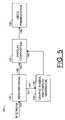
- FIG. 5is a more detailed block diagram illustrating an example decoder/analyzer of FIG. 4 in accordance with a preferred embodiment of the present invention
- FIG. 6is an example display illustrating a decoded video display and various analysis tools
- FIG. 7is an example display illustrating a high-level on-screen statistics overlay in accordance with a preferred embodiment of the present invention.
- FIG. 8is a block diagram illustrating various examples of graphic symbols in accordance with a preferred embodiment of the present invention.
- FIG. 9is an example display illustrating an overlay containing graphic symbols representing macroblock partitioning information
- FIG. 10is an example display illustrating an overlay comprising graphic symbols representing macroblock size and macroblock quantization parameter information
- FIG. 11is an example display illustrating an overlay comprising graphic symbols representing motion vectors and reference indices
- FIG. 12is an example display illustrating an overlay image comprising information regarding MBAFF structure
- FIG. 13is a diagram illustrating an example display format for reporting pixel values
- FIG. 14is a more detailed block diagram illustrating an example of a macroblock histogram of FIG. 6 ;
- FIG. 15is a more detailed block diagram illustrating an example of a group of pictures histogram of FIG. 6 .
- a data stream(e.g., a video stream) may comprise a series of source pictures 70 a - n .
- the source picturesmay also be referred to as images, frames, a group-of-pictures (GOP) or a sequence.
- the picturesgenerally comprise contiguous rectangular arrays of pixels (i.e., picture elements).
- Video sequencescontain a high degree of: 1) spatial redundancy, due to the correlation between neighboring pixels, 2) spectral redundancy, due to correlation among the color components, 3) temporal redundancy, due to correlation between video frames, and 4) psycho-visual redundancy, due to properties of the human visual system (HVS).
- HVShuman visual system
- Video framesgenerally comprise three rectangular matrices of pixel data representing a luminance signal (e.g., luma Y) and two chrominance signals (e.g., chroma Cb and Cr) that correspond to a decomposed representation of the three primary colors (e.g., Red, Green and Blue) associated with each picture element.
- a luminance signale.g., luma Y
- two chrominance signalse.g., chroma Cb and Cr
- the most common format used in video compression standardsis eight bits and 4:2:0 sub-sampling (e.g., the two chroma components are reduced to one-half the vertical and horizontal resolution of the luma component).
- other formatsmay be implemented to meet the design criteria of a particular application.
- Each picturemay comprise a complete frame of video (e.g., a frame picture) or one of two interlaced fields from an interlaced source (e.g., a field picture).
- the field picturegenerally does not have any blank lines between the active lines of pixels. For example, if the field picture is viewed on a normal display, the field picture would appear short and fat.
- the two fieldsmay be encoded together as a frame picture. Alternatively, the two fields may be encoded separately as two field pictures. Both frame pictures and field pictures may be used together in a single interlaced sequence. High detail and limited motion generally favors frame picture encoding. In general, field pictures occur in pairs (e.g., top/bottom, odd/even, field 1 /field 2 ).
- the output of a decoding process for an interlaced sequenceis generally a series of reconstructed fields.
- all pictures in the sequenceare frame pictures.
- the output of a decoding process for a progressive sequenceis generally a series of reconstructed frames.
- the source pictures 70 a - nmay be presented to an encoder 72 .
- the encoder 72may be configured to generate a series of encoded pictures 74 a - n in response to the source pictures 70 a - n , respectively.
- the encoder 72may be configured to generate the encoded pictures 74 a - n using a compression standard (e.g., MPEG-2, MPEG-4, H.264, etc.).
- a compression standarde.g., MPEG-2, MPEG-4, H.264, etc.
- encoded picturesmay be classified as intra coded pictures (I), predicted pictures (P) and bi-predictive pictures (B).
- Intra coded picturesare generally coded without temporal prediction. Rather, intra coded pictures use spatial prediction within the same picture.
- an intra coded pictureis generally coded using information within the corresponding source picture (e.g., compression using spatial redundancy).
- An intra coded pictureis generally used to provide a receiver with a starting point or reference for prediction.
- intra coded picturesmay be used after a channel change and to recover from errors.
- Predicted picturese.g., P-pictures or P-frames
- bi-predictive picturese.g., B-pictures or B-frames
- Inter coding techniquesare generally applied for motion estimation and/or motion compensation (e.g., compression using temporal redundancy).
- P-pictures and B-picturesmay be coded with forward prediction from references comprising previous I and P pictures.
- the B-picture 74 b and the P-picture 74 cmay be predicted using the I-picture 74 a (e.g., as indicated by the arrows 76 and 78 , respectively).
- the B-picturesmay also be coded with (i) backward prediction from a next I or P-reference picture (e.g., the arrow 80 ) or (ii) interpolated prediction from both past and future I or P-references (e.g., the arrows 82 a and 82 b , respectively).
- portions of P and B-picturesmay also be intra coded or skipped (e.g., not sent at all). When a portion of a picture is skipped, the decoder generally uses the associated reference picture to reconstruct the skipped portion with no error.
- P-picturesmay reference temporally forward or backward.
- B-picturesmay have similar forward or backward references.
- the restrictionis generally not time, but rather how many frames are stored in a buffer so that the frames may be decoded in a different order than the frames are displayed.
- the framesmay be referenced forward in time.
- the framesmay be referenced backward in time (e.g., re-ordering the frames).
- a B-framemay differ from a P-frame in that a B-frame may do interpolated prediction from any two reference frames. Both reference frames may be (i) forward in time, (ii) backward in time, or (iii) one in each direction. B-pictures can be, and are expected to often be, used as prediction references in H.264. In many cases an important distinction is between reference and non-reference frames.
- the encoded pictures 74 a - nmay be presented to a decoder 84 .
- the decoder 84is generally configured to generate a series of reconstructed pictures corresponding to the source pictures 70 a - 70 n (e.g., images, frames, fields, etc.) in response to the encoded pictures.
- the decoder 84may be implemented within the encoder 72 and the reconstructed pictures may be used in the prediction operations of the encoding process.
- a picture (or video frame) 70 imay be divided into a number of macroblocks 86 of equal size.
- the macroblocks 86may be implemented as 16 ⁇ 16 pixels. However, other size macroblocks may be implemented to meet the design criteria of a particular application.
- Motion compensated predictiongenerally presumes that a macroblock within the current picture 70 i may be modeled as a translation of a macroblock from a picture 70 ( i ⁇ 1 ).
- Each macroblock 86 in the current picture 70 imay be predicted from the reference picture 70 ( i ⁇ 1 ).
- the motion informationis generally represented as a two-dimensional displacement vector or motion vector 88 .
- motion estimationgenerally uses block-matching techniques that obtain the motion vector by minimizing a cost function measuring the mismatch between a candidate block and the current block.
- a number of reference pictures 70 ( i ⁇ 4 ), 70 ( i ⁇ 3 ) . . . 70 ( i ⁇ 1 )may be used to predict the macroblocks in the current picture 70 i.
- a block diagramis shown generally illustrating partitions or segments of pictures.
- a picturee.g., an image, a frame, a field, etc.
- the macroblocksgenerally comprise an array of pixels having vertical and horizontal dimensions of equal size (e.g., 32 ⁇ 32, 16 ⁇ 16, etc).
- the macroblocksgenerally comprise luminance data (e.g., luma Y) and chrominance data (e.g., blue chroma Cb and red chroma Cr).
- the luminance datamay have a resolution that is twice that of the chrominance data (e.g., a 4:2:0 format).
- the macroblocks 86may be grouped in a number of slices 90 .
- the slices 90may comprise an arbitrary number of macroblocks 86 .
- the slices 90generally run from left to right and may comprise an entire row of the picture 70 i .
- a slice 90may comprise less than or more than an entire row of macroblocks 86 (e.g., H.264 compliant).
- a slice 90may be defined as a particular number of macroblocks 86 grouped together.
- the macroblocks 86 in a slice 90are generally consecutive macroblocks in raster scan order.
- a mapmay be sent identifying which scattered macroblocks are grouped together in a slice.
- a compression standardmay also provide an option of using macroblocks or macroblock pairs.
- a macroblock paircomprises two macroblocks located one above the other.
- a slice or rowgenerally comprises macroblock pairs rather than macroblocks.
- the macroblock 86may be implemented as a 16 ⁇ 16 block.
- the macroblock 86may be encoded in an inter prediction mode (e.g., compression based upon temporal redundancy) or an intra prediction mode (e.g., compression based upon spatial redundancy).
- inter prediction modee.g., compression based upon temporal redundancy
- intra prediction modee.g., compression based upon spatial redundancy
- each 16 ⁇ 16 macroblock 86may be predicted with a single 16 ⁇ 16 vector (e.g., mode 1).
- the macroblock 86may be segmented into two 16 ⁇ 8 blocks (e.g., mode 2) or two 8 ⁇ 16 blocks (e.g., mode 3), in which case two motion vectors may be generated for predicting the macroblock 86 .
- the macroblock 86may also be segmented into four 8 ⁇ 8 blocks (e.g., mode 4), in which case four motion vectors may be generated for the macroblock 86 .
- each 8 ⁇ 8 blockmay be optionally further segmented into two 4 ⁇ 8 sub-blocks (e.g., mode 5), two 8 ⁇ 4 sub-blocks (e.g., mode 6) or four 4 ⁇ 4 sub-blocks (e.g., mode 7).
- An encodergenerally decides which “mode” to use for encoding each macroblock 86 .
- an error scoremay be computed based on a closeness of match determination for each mode, with the modes that use more vectors being penalized (e.g., by increasing the respective error score) because of the additional bits that it will take to encode the motion vectors.
- the prediction blockis generally formed for the entire 8 ⁇ 8 chroma block. Both chroma Cb and chroma Cr blocks are generally processed similarly. In general, one of four prediction modes may be used (e.g., DC or mode 0, vertical or mode 1, horizontal or mode 2, and plane or mode 3).
- a content provider 102presents video image, audio or other data 104 to be compressed and transmitted to an input of an encoder 106 .
- the compressed data 108 from the encoder 106may be presented to an encoder transport system 110 .
- An output of the encoder transport system 110generally presents a signal 112 to a transmitter 114 .
- the transmitter 114transmits the compressed data via a transmission medium 116 .
- the content provider 102may comprise a video broadcast, DVD, or any other source of video data stream.
- the transmission medium 116may comprise a broadcast, cable, satellite, network, DVD, hard drive, or any other medium implemented to carry, transfer, and/or store a compressed bitstream.
- a receiver 118On a receiving side of the system 100 , a receiver 118 generally receives the compressed data bitstream from the transmission medium 116 .
- the receiver 118presents an encoded bitstream 120 to a decoder transport system 122 .
- the decoder transport system 122generally presents the encoded bitstream via a link 124 to a decoder/analyzer 126 .
- the decoder/analyzer 126generally decompresses (decodes) the data bitstream and presents the data via a link 128 to an end user 130 .
- the decoder/analyzer 126is generally configured to also present information (e.g., a number of overlays that may include graphic symbols) regarding bitstream syntax elements via the link 128 .
- the end user 130may comprise a television, a monitor, a computer, a projector, a hard drive, or any other medium implemented to carry, transfer, present, display and/or store the uncompressed bitstream (decoded video signal) and/or information regarding the bitstream syntax elements.
- the present inventiongenerally provides a graphical display of syntax elements as well as other bitstream parameters and statistics overlaid upon the decoded video frames.
- Each encoded picturegenerally consists of 16 ⁇ 16 blocks of pixel data called macroblocks.
- macroblocksmay be implemented accordingly to meet the design criteria of a particular application.
- the present inventiongenerally overlays macroblock syntax elements that may include but are not limited to: macroblock type, sub-macroblock types and prediction directions; macroblock encoded size; macroblock quantization parameter; macroblock reference index; macroblock motion vectors; macroblock adaptive field/frame (MBAFF) structure; macroblock pixel values; macroblock frequency coefficients.
- macroblock type histogram and a macroblock gridmay also be overlaid.
- the present inventionfacilitates the correlation of the macroblock syntax elements to the video content by presenting the bitstream syntax information in such a manner that the information may be displayed over the corresponding decoded video.
- the decoder/analyzer (or circuit) 126may be configured to decode an encoded bitstream (e.g., BITSTREAM).
- the signal BITSTREAMmay comprise an H.264 compliant video bitstream and the circuit 126 may be implemented as an H.264 decoder/analyzer.
- the circuit 126may be configured to generate a decoded video signal and one or more overlay images (e.g., graphical displays) comprising information about syntax elements contained in the encoded bitstream.
- the circuit 126may comprise a block (or circuit) 132 , a block (or circuit) 134 , a block (or circuit) 136 and a block (or circuit) 138 .
- the block 132may be implemented, in one example, as a video decoding circuit.
- the block 134may be implemented, in one example, as a graphic symbol and overlay generator.
- the block 136may be implemented as an overlay compositing block.
- the block 138may be implemented as a video presentation block.
- the signal BITSTREAMmay be presented to an input 140 of the block 132 .
- the block 132may be configured to decode video information from the signal BITSTREAM.
- the circuit 132may have an output 141 that may present syntax elements and information extracted from the signal BITSTREAM to an input 142 of the block 134 (e.g., as one or more signals INT) and an output 143 that may present a decoded video signal to an input 144 of the block 136 .
- the block 134may be configured to generate a number of overlay images comprising graphic symbols representing syntax elements in the encoded bitstream BITSTREAM.
- the block 134may be further configured to generate a number of statistics with respect to the syntax elements of the signal BITSTREAM.
- the block 134may be configured to present the graphic symbols representing the syntax elements and the statistics regarding the encoded bitstream in the one or more graphic overlay images (or windows) to an input 146 of the block 136 .
- the block 136may be configured to generate a composited video image in response to the decoded video signal from the block 132 and the one or more overlay images from the block 134 .
- the block 136may be configured to present a signal comprising the composited video image to an input 148 of the block 138 .
- the block 138may be configured to present the composited video signal to a user of the decoder/analyzer 126 .
- an example display 150is shown illustrating an example output of the circuit 126 with analyzer tools turned on.
- the display 150generally illustrates a graphical user interface (GUI) in accordance with a preferred embodiment of the present invention.
- GUIgraphical user interface
- the display 150may comprise a main window 152 , a statistics window 154 , a legend window 156 and a pixel values window 158 .
- other windowsmay be implemented accordingly to meet the design criteria of a particular application.
- the decoded videois generally presented in the main window 152 .
- the main window 152may also be configured to display corresponding bitstream syntax elements overlaid on the decoded video.
- the present interfaceprovides visual correlation between the syntax elements and specific locations in the decode video.
- the statistics window 154may be implemented (e.g., in the upper right corner) to display picture level parameters and statistics (e.g., a macroblock histogram 160 , a group-of-pictures histogram 162 , picture type/size, etc.) as well as some detailed macroblock level parameters about a macroblock selected by, for example, a mouse pointer.
- the parametersmay include coordinates of the selected macroblock within the picture.
- MCAFFmacroblock level adaptive frame/field
- each macroblock pairmay be coded in a frame or field mode.
- a string(e.g., “FRAME”) may be displayed in the window 154 for macroblocks encoded in the frame mode.
- top macroblockse.g., even vertical position
- bottom macroblockse.g., odd vertical position
- the legend window 156may be displayed (e.g., in the bottom right corner) to provide a description of the on-screen graphical symbols presented in the overlay image in the window 152 .
- the window 158may be implemented to enumerate the pixel values (e.g., luma and chroma) of the selected macroblock.
- a grid(illustrated in FIGS. 9-12 below) representing the macroblocks of the decoded video may be displayed in the window 152 to highlight the macroblock boundaries (e.g., 16 ⁇ 16 pixels, etc.) with a thin line.
- the macroblock gridgenerally renders the information relevant to each macroblock inside the respective macroblock area (described in more detail in connection with FIGS. 9-12 below).
- the macroblock gridgenerally provides the user with visual correlatation between the macroblock parameters and the decoded video.
- an overlay display 170is shown illustrating an example high-level on-screen statistics overlay.
- the present inventionmay provide a graphic user interface (GUI) for the decoder/analyzer 126 .
- GUIgraphic user interface
- the GUImay provide information to the user at a number of different levels.
- the circuit 126may be configured to display decoded video only, in which case the circuit 126 does not generally provide detailed information about the encoded bitstream to the user.
- the circuit 126may be configured to display high level information about the decoded video signal such as video resolution, frame rate, and bit rates.
- the circuit 126may be configured to also display low-level bitstream syntax elements.
- a GUI in accordance with the present inventionmay be configured to display high-level video statistics as an overlay on the decoded video in the main window 152 (e.g., in the top-left corner, etc.).
- the displayed statisticsmay include, but are not limited to: resolution, frame rate, bit rate, a bit rate graph 172 , bitstream errors, peak signal to noise ratio (PSNR), average PSNR and a PSNR graph 174 .
- Other statisticsmay be displayed accordingly to meet the design criteria of a particular application.
- the resolution of the decoded video in pixelsmay be displayed in a width ⁇ height format.
- the frame ratemay be displayed as the actual frame rate (e.g., in frames per second).
- the bit rate statisticmay comprise a current and/or average bit rate (e.g., in megabits per second).
- the bit rate graph 172may be configured, in one example, to display a time history of the bit rate of the signal BITSTREAM.
- the timemay be represented on one axis (e.g., the horizontal scale) and the bit rate may be displayed on another axis (e.g., the vertical scale).
- the vertical bit rate scalemay be dynamically adjusted.
- the maximum value of the graphmay be increased, in one example, to a next higher integer number of megabits.
- the vertical scale of the graph 172may be configured to indicate the maximum bit rate reached since the decoder was started.
- the bit rate graph 172may be color coded.
- the video bit ratemay be displayed in the color blue, the audio bit rate in light green and the total bit rate in brown.
- other colorsmay be employed accordingly to meet the design criteria of a particular application.
- a thin horizontal linemay be implemented across the graph 172 to indicate the average bit rate.
- the errors valuegenerally indicates a number of incorrectly decoded pictures.
- the error statisticmay be implemented similarly to a CRC. However, other types of errors may be tracked and displayed accordingly.
- the PSNR displaymay comprise the current PSNR(Y, U, V) and an average PSNR in decibels (dB) for the decoded video. In one example, the Y, U and V channels may be displayed separately.
- the PSNR graph 174may be configured to display a time history of the luminance PSNR. For example, the time may be plotted on the horizontal scale and the PSNR plotted on the vertical scale. The vertical PSNR scale may be dynamically adjusted.
- the maximum value of the graph 174may be increased to the next higher integer number of decibels.
- the minimum value of the graph 174may be decreased to a next lower integer number of decibels.
- the vertical scale of the graphmay indicate the minimum and maximum PSNR reached since the decoder was started.
- the legend windowgenerally provides information for interpreting a macroblock grid overlay in the main window 152 .
- the macroblock parametersgenerally comprise macroblock type, sub-macroblock types and prediction directions.
- the macroblock (MB) typegenerally specifies how a macroblock (e.g., a 16 ⁇ 16 block of video frame pixels) is partitioned (or segmented) and/or encoded.
- the MB typesgenerally include, but are not limited to, Intra16 ⁇ 16, Intra4 ⁇ 4, Skip, Direct, Inter and PCM.
- the macroblock type informationmay be displayed with different shapes, shadings and/or colors. In one example, shapes and colors may be implemented as follows:
- the color-coding for inter predicted macroblocksmay, in one example, depend upon the prediction direction.
- Blocks coded in Inter16 ⁇ 16, Inter16 ⁇ 8, Inter8 ⁇ 16 macroblocks and all sub-partitions in Inter8 ⁇ 8 typemay be predicted using list 0 , list 1 or both lists.
- the prediction listgenerally represents, which reference frame out of two choices (list 0 and list 1 ) is used to predict a bi-predictive macroblock or a sub-partition.
- all blocks predicted using list 0may be displayed in one color (e.g., red), all blocks predicted using list 1 may be displayed in another color (e.g., blue color), and all blocks predicted using both list 0 and list 1 may be displayed in yet another color (e.g., purple color).
- one colore.g., red
- all blocks predicted using list 1may be displayed in another color (e.g., blue color)
- all blocks predicted using both list 0 and list 1may be displayed in yet another color (e.g., purple color).
- the legend window 156may include symbols (e.g., lines) that may be used to indicate prediction direction. For example, a line may be displayed in each section of the macroblock grid indicating a motion vector direction (described in more detail in connection with FIG. 11 ). In one example, forward referenced vectors may be colored red and backward directed vectors may be colored blue.
- FIG. 9a diagram illustrating an example of the window 152 presenting a macroblock grid overlay comprising macrboblock partition and encoding information is shown.
- Each square in the macroblock grid in the window 152may include a graphic symbol representing the macroblock type information for the respective macroblock.
- the graphic symbolsrepresent the partitioning and encoding information for a respective macroblock.
- the decoded video imageis generally visible through the overlay, but has been omitted for clarity.
- each macroblock grid element 180may comprise a graphic element (or symbol) 182 and a graphic element or symbol) 184 .
- the symbol 182may represent the macroblock size parameter for the respective macroblock.
- the symbol 184may represent the quantization parameter for the respective macroblock.
- the macroblock size parameter 182generally represents the number of bits used to encode the syntax elements of the macroblock.
- the macroblock size parametermay be displayed as a solid rectangle. In one example, the rectangle may be color coded (e.g., pink, etc.). The size of the rectangle may be representative of a relative size of the macroblock.
- the macroblock quantization parameter 184 for a macroblockmay have a value, for example, in a range from 0 to 51.
- the macroblock quantization parametermay be displayed, in one example, as an integer number.
- the size of the rectanglemay be determined by the following example process:
- other methods for determining the rectangle dimensionsmay be implemented accordingly to meet the design criteria of a particular application.
- the decoded video imageis generally visible through the overlay, but has been omitted for clarity.
- a macroblock grid element 190may comprise a graphic element (or symbol) 192 and a graphic element (or symbol) 194 .
- the symbol 192may represent the reference index for the respective macroblock.
- the symbol 194may represent one or more motion vectors for the respective macroblock.
- the reference index 192generally specifies the index of the reference frame that is used to predict a macroblock partition or sub-partition. At least one reference index is generally transmitted for every inter coded 16 ⁇ 16, 16 ⁇ 8, 8 ⁇ 16 block and every inter coded 8 ⁇ 8 sub-partition.
- the list 0 reference index of the top-left block in a macroblockif present in the bitstream, may be displayed as an integer number (e.g., 0, 1, etc.).
- the list 1 reference indicesmay also be displayed accordingly.
- one or two motion vectorsare transmitted for every block and every sub-partition block in an inter-predicted macroblock.
- the motion vectorsmay be displayed, in one example, as thin lines with the origin at the top-left corner of each macroblock grid element (e.g., the vector 194 ).
- the top-left motion vectormay be displayed to determine whether the true motion vector was detected and individual motion vectors may be displayed as numerical values in another location on the screen.
- the motion vector originmay be marked with a small dot.
- the list 0 motion vectorsmay be displayed in a red color and the list 1 motion vectors may be displayed in a blue color.
- each macroblock pairmay be coded in a frame or field mode.
- a lowercase lettere.g., “f”
- fa lowercase letter
- other symbolsmay be implemented accordingly to meet the design criteria of a particular application.
- the window 158may present values of all pixels for one or more selected macroblocks. For example, luminance (Luma or Y) and both chrominance (Chroma or Cr and Cb) components may be displayed in separate areas of the window 158 . In general, each value (e.g., Y, Cr, Cb) may be displayed as an unsigned 8-bit value.
- a coded block pattern (CBP) windowmay be implemented to display macroblock coded block patterns.
- the coded block patterngenerally signals whether an 8 ⁇ 8 block within a macroblock has any coefficients.
- the luminance componentgenerally has 4 8 ⁇ 8 blocks (e.g., L 0 , L 1 , L 2 , L 3 ) and each chroma component in 4:2:0 format generally has one 8 ⁇ 8 block (e.g., Cb and Cr).
- the coded block patternmay be displayed in the following format:
- the macroblock histogram 160generally comprises a histogram graph displaying the relative usage of different block types within a picture.
- the types of all 8 ⁇ 8 blocksmay be used to create the histogram.
- the block typesmay be indicated by associated colors and/or shading.
- a color codingmay be implemented as follows:
- the width of a section of the histogrammay represent the number of blocks of a particular type relative to all blocks in the image.
- the histogram 162generally displays the type (e.g., I, B, P) and encoded size of each picture in a group-of-pictures sequence.
- the type informationmay be represented by shading and/or color.
- the encoded sizemay be represented by the height of each bar.
- the window 152may be implemented with a zoom and/or pan capability.
- each macroblock in the macroblock grid overlaymay be displayed using more than 16 ⁇ 16 pixels in the displayed area.
- more macroblock statisticsmay be drawn in the actual display area.
- the present inventionmay comprise software configured to use overlay hardware in PC video cards to display on-screen statistics in real-time.
- the video picturemay be upscaled first and then the grid and macroblock statistics may be rendered on top of the video picture.
- the video presented by an H.264 decoderis generally in a YUV420 format.
- the following stepsmay be performed:
- the processmay be repeated 30 times a second, for an NTSC video.
- other repeat ratesmay be implemented to meet the design criteria of a particular application (e.g., 25 times per second for SECAM or PAL).
- YUV to RGB conversionis generally CPU expensive and takes additional buffer space to store the RGB data.
- Good quality up-scalingis also very CPU expensive and may take an even larger buffer to store the up-scaled picture.
- the rendering of the on-screen statisticsis generally performed for every picture since the previous picture is usually overwritten by the current one.
- the memory bandwidth used to move the video data to the video cardmay be substantial (e.g., 173 MB/s for a display with resolution 1600 ⁇ 1200).
- an optionmay be implemented (e.g., in a menu screen not shown) for the on-screen statistics to be hidden (e.g., a mode with analyzer tools turned off).
- the various example overlays presentedare shown as black on white for clarity.
- the text and graphic symbolsmay be implemented with opaque backgrounds and/or color coding configured to contrast with the decoded video image.
- the backgrounds of the text and graphic overlays displayed in the window 152may be configured to be transparent and may be replaced by the decoded video during playback, for example, using video overlay hardware.
- the overlay hardwaremay significantly accelerate the steps listed above and offload most of the work from the CPU, which may already be used by a complex H.264 decoder.
- the overlay hardwareis generally capable of (i) converting YUV data into RGB, (ii) up-scaling the video into almost any resolution and (iii) displaying the result in a settable destination area on the video display.
- the overlay hardwaremay perform the operations without any intervention from the system CPU.
- Another very useful feature of the overlay hardwareis that the resulting picture generally does not overwrite the video memory. The picture is rather created on-the-fly as the memory is being read to drive the electron-beam. In one example, only specific pixels in the destination area are substituted with such a virtual picture.
- the circuit 126may be configured to setup the overlay hardware to transform the decoded video in YUV format to a destination rectangle in RGB format (e.g., the window 152 ) on the display and to specify which color in the destination rectangle to substitute with the overlay video.
- the circuit 126may wait for a vertical blanking interval before copying the picture to the source location of the overlay hardware. Waiting for the vertical blanking interval generally guarantees a flicker-free video playback.
- a client area of an application implemented in accordance with the present inventionis generally erased with the color used to setup the overlay hardware to display the decoded video.
- the decoderthen uses the client area to display any statistics and the video playback will not overwrite the overlay.
- the imagestays there without a need for refreshing with every video picture while the video playback is running.
- most of the statisticsare updated less frequently than the video frame rate and the decoder application may update the statistics independently from the video playback minimizing the CPU usage.
- the displayis generally updated in-sync with the decoded video to display the correct data for each picture.
- the number of graphical operationsis generally significantly higher in this mode, because most of the client area of the decoder application is updated for every picture.
- the applicationgenerally does not put too much load on the CPU, because existing video cards generally have graphics accelerators.
- the actual drawing into the video memorymay be performed directly by the video card graphics accelerator rather than the system CPU.
- the graphics acceleratormay send graphical commands to the video card minimizing both the CPU load as well as the memory bandwidth.
- the on-screen statisticsmay be updated in the vertical blanking interval for a flicker-free display. However, updating only during the vertical blanking interval is generally not necessary in most cases, because the on-screen statistics are generally updated infrequently and the change is usually very small so as not to produce noticeable flicker artifacts.
- the present inventionmay make use of simple color-coded symbols, which are easy and fast to read, to display H.264 bitstream syntax elements as an overlay over the decoded video.
- the simultaneous display of both the decoded video and the H.264 bitstream syntax elementsmay significantly speed up codec (encoder/decoder), verification, and analysis of video bitstreams.
- the present inventionmay be used to also display syntax elements in previous and/or future encoding formats.
- the present inventionmay be implemented using a conventional general purpose digital computer programmed according to the teachings of the present specification, as will be apparent to those skilled in the relevant art(s).
- Appropriate software codingcan readily be prepared by skilled programmers based on the teachings of the present disclosure, as will also be apparent to those skilled in the relevant art(s).
- the present inventionmay also be implemented by the preparation of ASICs, FPGAs, or by interconnecting an appropriate network of conventional component circuits, as is described herein, modifications of which will be readily apparent to those skilled in the art(s).
- the present inventionthus may also include a computer product which may be a storage medium including instructions which can be used to program a computer to perform a process in accordance with the present invention.
- the storage mediumcan include, but is not limited to, any type of disk including floppy disk, optical disk, CD-ROM, and magneto-optical disks, ROMs, RAMs, EPROMs, EEPROMs, Flash memory, magnetic or optical cards, or any type of media suitable for storing electronic instructions.
- the term “simultaneously”is meant to describe events that share some common time period but the term is not meant to be limited to events that begin at the same point in time, end at the same point in time, or have the same duration.
Landscapes
- Engineering & Computer Science (AREA)
- Multimedia (AREA)
- Signal Processing (AREA)
- Compression Or Coding Systems Of Tv Signals (AREA)
Abstract
Description
- Intra16×16: Displayed as a solid square in a white color.
- Intra4×4: Displayed as a grid of 4×4 solid squares in, for example, a white color.
- Skip: Displayed as a transparent square with, for example, a red border.
- Direct Displayed as a solid square in, for example, a light green color.
- Inter The inter macroblock type may exist in a number of different sizes:
- 16×16—contains one 16×16 block, displayed as a solid square,
- 16×8—contains two 16×8 blocks, displayed as two solid rectangles,
- 8×16—contains two 8×16 blocks, displayed as two solid rectangles,
- 8×8—contains four 8×8 macroblock sub-partitions, each sub-partition may be displayed in a square and may be one of the following types or sizes:
- Direct8×8 displayed as a small solid square in, for example, a light green color,
- Inter8×8 displayed as a small solid square,
- Inter8×4 displayed as two small rectangles,
- Inter4×8 displayed as two small rectangles,
- Inter4×4 displayed as four small squares.
- PCM Displayed as a solid square in, for example, a yellow color.
- Set a pair of variables (e.g., min_mb_size and max_mb_size) to the minimum and maximum macroblock size, respectively, within the current picture.
- For all macroblocks in the current picture
| { | ||
| mb_size = getMBsize(curr_x, curr_y); | |
| square_size = 1.14 * sqrt((mb_size - min_mb_size) * 255 | |
| / (max_mb_size-min_mb_size)); | |
| DrawSquare(curr_x, curr_y, square_size); |
| } | ||
However, other methods for determining the rectangle dimensions may be implemented accordingly to meet the design criteria of a particular application. The decoded video image is generally visible through the overlay, but has been omitted for clarity.
- L0L1L2L3 CdcCac
where Cdc indicates a presence of any chroma DC coefficients and Cac indicates a presence of any chroma AC coefficients. A first symbol (e.g., “*”) may be used to indicate blocks with any coefficients, while a second symbol (e.g., “.”) may be used to indicate blocks with no coefficients. For example, a string “**.**.” may indicate that luma blocks0,1 and3 have coefficients presented, while there are no coefficients coded in the bitstream forluma block 2 and only chroma DC coefficients are presented in the bitstream. The coefficients for a selected macroblock may be displayed in a separate window in the same manner as the pixel values. In one example, only the coefficients of 8×8 blocks for which the CBP indicates the presence of any coefficients are generally displayed.
- L0L1L2L3 CdcCac
| Intra16 × 16 | white | ||
| Intra4 × 4 | gray | ||
| Skip | light red | ||
| Direct | light green | ||
| Inter, list0 | red | ||
| Inter, list1 | blue | ||
| Inter, list0 and list1 | purple | ||
| PCM | yellow | ||
In one example, the width of a section of the histogram may represent the number of blocks of a particular type relative to all blocks in the image.
- a) converting the video information from YUV to RGB;
- b) up-scaling the converted video information to a desired size and aspect ratio;
- c) rendering the on-screen statistics to the video picture;
- d) moving the created picture to a display memory of a video card.
Claims (22)
Priority Applications (1)
| Application Number | Priority Date | Filing Date | Title |
|---|---|---|---|
| US10/720,783US7362804B2 (en) | 2003-11-24 | 2003-11-24 | Graphical symbols for H.264 bitstream syntax elements |
Applications Claiming Priority (1)
| Application Number | Priority Date | Filing Date | Title |
|---|---|---|---|
| US10/720,783US7362804B2 (en) | 2003-11-24 | 2003-11-24 | Graphical symbols for H.264 bitstream syntax elements |
Publications (2)
| Publication Number | Publication Date |
|---|---|
| US20050123282A1 US20050123282A1 (en) | 2005-06-09 |
| US7362804B2true US7362804B2 (en) | 2008-04-22 |
Family
ID=34633250
Family Applications (1)
| Application Number | Title | Priority Date | Filing Date |
|---|---|---|---|
| US10/720,783Expired - Fee RelatedUS7362804B2 (en) | 2003-11-24 | 2003-11-24 | Graphical symbols for H.264 bitstream syntax elements |
Country Status (1)
| Country | Link |
|---|---|
| US (1) | US7362804B2 (en) |
Cited By (43)
| Publication number | Priority date | Publication date | Assignee | Title |
|---|---|---|---|---|
| US20060233122A1 (en)* | 2005-04-14 | 2006-10-19 | Vqual Limited | Method and apparatus for improved data analysis |
| US20090161770A1 (en)* | 2007-12-20 | 2009-06-25 | Dong Ruijing Ray | Coding adaptive deblocking filter and method for use therewith |
| US20100104021A1 (en)* | 2008-10-27 | 2010-04-29 | Advanced Micro Devices, Inc. | Remote Transmission and Display of Video Data Using Standard H.264-Based Video Codecs |
| US20110090351A1 (en)* | 2009-10-20 | 2011-04-21 | Apple Inc. | Temporal filtering techniques for image signal processing |
| US20110090381A1 (en)* | 2009-10-20 | 2011-04-21 | Apple Inc. | System and method for processing image data using an image processing pipeline of an image signal processor |
| US20110090371A1 (en)* | 2009-10-20 | 2011-04-21 | Apple Inc. | System and method for detecting and correcting defective pixels in an image sensor |
| US20110090370A1 (en)* | 2009-10-20 | 2011-04-21 | Apple Inc. | System and method for sharpening image data |
| US20110091101A1 (en)* | 2009-10-20 | 2011-04-21 | Apple Inc. | System and method for applying lens shading correction during image processing |
| US20120189062A1 (en)* | 2011-01-26 | 2012-07-26 | Toshiyasu Sugio | Moving picture coding method, moving picture coding apparatus, moving picture decoding method, moving picture decoding apparatus, and moving picture coding and decoding apparatus |
| US8471932B2 (en) | 2010-09-30 | 2013-06-25 | Apple Inc. | Spatial filtering for image signal processing |
| US8488055B2 (en) | 2010-09-30 | 2013-07-16 | Apple Inc. | Flash synchronization using image sensor interface timing signal |
| US8493482B2 (en) | 2010-08-18 | 2013-07-23 | Apple Inc. | Dual image sensor image processing system and method |
| US8508621B2 (en) | 2010-09-30 | 2013-08-13 | Apple Inc. | Image sensor data formats and memory addressing techniques for image signal processing |
| US8508612B2 (en) | 2010-09-30 | 2013-08-13 | Apple Inc. | Image signal processor line buffer configuration for processing ram image data |
| US8525895B2 (en) | 2010-07-29 | 2013-09-03 | Apple Inc. | Binning compensation filtering techniques for image signal processing |
| US8531542B2 (en) | 2010-09-01 | 2013-09-10 | Apple Inc. | Techniques for acquiring and processing statistics data in an image signal processor |
| US8605167B2 (en) | 2010-09-01 | 2013-12-10 | Apple Inc. | Flexible color space selection for auto-white balance processing |
| US8629913B2 (en) | 2010-09-30 | 2014-01-14 | Apple Inc. | Overflow control techniques for image signal processing |
| US20140105275A1 (en)* | 2007-12-20 | 2014-04-17 | Vixs Systems, Inc. | Adaptive partition subset selection module and method for use therewith |
| US8736700B2 (en) | 2010-09-30 | 2014-05-27 | Apple Inc. | Techniques for synchronizing audio and video data in an image signal processing system |
| US8786625B2 (en) | 2010-09-30 | 2014-07-22 | Apple Inc. | System and method for processing image data using an image signal processor having back-end processing logic |
| US8817120B2 (en) | 2012-05-31 | 2014-08-26 | Apple Inc. | Systems and methods for collecting fixed pattern noise statistics of image data |
| US8872946B2 (en) | 2012-05-31 | 2014-10-28 | Apple Inc. | Systems and methods for raw image processing |
| US8917336B2 (en) | 2012-05-31 | 2014-12-23 | Apple Inc. | Image signal processing involving geometric distortion correction |
| US8922704B2 (en) | 2010-09-01 | 2014-12-30 | Apple Inc. | Techniques for collection of auto-focus statistics |
| US8954876B1 (en)* | 2007-10-09 | 2015-02-10 | Teradici Corporation | Method and apparatus for providing a session status indicator |
| US8953882B2 (en) | 2012-05-31 | 2015-02-10 | Apple Inc. | Systems and methods for determining noise statistics of image data |
| US9014504B2 (en) | 2012-05-31 | 2015-04-21 | Apple Inc. | Systems and methods for highlight recovery in an image signal processor |
| US9025867B2 (en) | 2012-05-31 | 2015-05-05 | Apple Inc. | Systems and methods for YCC image processing |
| US9031319B2 (en) | 2012-05-31 | 2015-05-12 | Apple Inc. | Systems and methods for luma sharpening |
| US9077943B2 (en) | 2012-05-31 | 2015-07-07 | Apple Inc. | Local image statistics collection |
| US9087260B1 (en)* | 2012-01-03 | 2015-07-21 | Google Inc. | Hierarchical randomized quantization of multi-dimensional features |
| US9105078B2 (en) | 2012-05-31 | 2015-08-11 | Apple Inc. | Systems and methods for local tone mapping |
| US9131196B2 (en) | 2012-05-31 | 2015-09-08 | Apple Inc. | Systems and methods for defective pixel correction with neighboring pixels |
| US9142012B2 (en) | 2012-05-31 | 2015-09-22 | Apple Inc. | Systems and methods for chroma noise reduction |
| US9332239B2 (en) | 2012-05-31 | 2016-05-03 | Apple Inc. | Systems and methods for RGB image processing |
| US9398205B2 (en) | 2010-09-01 | 2016-07-19 | Apple Inc. | Auto-focus control using image statistics data with coarse and fine auto-focus scores |
| US10157480B2 (en) | 2016-06-24 | 2018-12-18 | Microsoft Technology Licensing, Llc | Efficient decoding and rendering of inter-coded blocks in a graphics pipeline |
| US10347017B2 (en)* | 2016-02-12 | 2019-07-09 | Microsoft Technology Licensing, Llc | Interactive controls that are collapsible and expandable and sequences for chart visualization optimizations |
| US10575007B2 (en) | 2016-04-12 | 2020-02-25 | Microsoft Technology Licensing, Llc | Efficient decoding and rendering of blocks in a graphics pipeline |
| US10748312B2 (en) | 2016-02-12 | 2020-08-18 | Microsoft Technology Licensing, Llc | Tagging utilizations for selectively preserving chart elements during visualization optimizations |
| US11089247B2 (en) | 2012-05-31 | 2021-08-10 | Apple Inc. | Systems and method for reducing fixed pattern noise in image data |
| US11197010B2 (en) | 2016-10-07 | 2021-12-07 | Microsoft Technology Licensing, Llc | Browser-based video decoder using multiple CPU threads |
Families Citing this family (19)
| Publication number | Priority date | Publication date | Assignee | Title |
|---|---|---|---|---|
| US7400681B2 (en)* | 2003-11-28 | 2008-07-15 | Scientific-Atlanta, Inc. | Low-complexity motion vector prediction for video codec with two lists of reference pictures |
| US7650603B2 (en)* | 2005-07-08 | 2010-01-19 | Microsoft Corporation | Resource management for virtualization of graphics adapters |
| US8619856B2 (en) | 2008-10-03 | 2013-12-31 | Qualcomm Incorporated | Video coding with large macroblocks |
| US8503527B2 (en) | 2008-10-03 | 2013-08-06 | Qualcomm Incorporated | Video coding with large macroblocks |
| US8665959B2 (en)* | 2010-04-12 | 2014-03-04 | Qualcomm Incorporated | Block and partition signaling techniques for video coding |
| US20120019559A1 (en)* | 2010-07-20 | 2012-01-26 | Siler Lucas C | Methods and Apparatus for Interactive Display of Images and Measurements |
| BR112013012814B1 (en)* | 2010-10-26 | 2019-10-08 | Nec Corporation | VIDEO DECODING DEVICE AND VIDEO DECODING METHOD |
| US20120207360A1 (en)* | 2011-02-11 | 2012-08-16 | Courosh Mehanian | Systems and Methods for Object Identification |
| KR20120095814A (en)* | 2011-02-21 | 2012-08-29 | 한밭대학교 산학협력단 | Methods of encoding/decoding using multiple reference pictures and apparatuses for using the same |
| US9094689B2 (en)* | 2011-07-01 | 2015-07-28 | Google Technology Holdings LLC | Motion vector prediction design simplification |
| CN103947206B (en) | 2011-10-14 | 2018-01-23 | 超威半导体公司 | The method and apparatus of compression of images based on region |
| CN104041041B (en) | 2011-11-04 | 2017-09-01 | 谷歌技术控股有限责任公司 | Motion vector scaling for the vectorial grid of nonuniform motion |
| JP2013125141A (en)* | 2011-12-14 | 2013-06-24 | Sony Corp | Display device, display method, transmitting device and transmitting method |
| US9172970B1 (en) | 2012-05-29 | 2015-10-27 | Google Inc. | Inter frame candidate selection for a video encoder |
| US11317101B2 (en) | 2012-06-12 | 2022-04-26 | Google Inc. | Inter frame candidate selection for a video encoder |
| US9621909B2 (en)* | 2012-07-02 | 2017-04-11 | Lg Electronics Inc. | Method for decoding image and apparatus using same |
| US9485515B2 (en) | 2013-08-23 | 2016-11-01 | Google Inc. | Video coding using reference motion vectors |
| US9503746B2 (en) | 2012-10-08 | 2016-11-22 | Google Inc. | Determine reference motion vectors |
| GB2576662B (en) | 2017-04-21 | 2020-10-28 | Zenimax Media Inc | Systems and methods for encoder-guided adaptive-quality rendering |
Citations (5)
| Publication number | Priority date | Publication date | Assignee | Title |
|---|---|---|---|---|
| US6011868A (en)* | 1997-04-04 | 2000-01-04 | Hewlett-Packard Company | Bitstream quality analyzer |
| US6525746B1 (en)* | 1999-08-16 | 2003-02-25 | University Of Washington | Interactive video object processing environment having zoom window |
| US6532024B1 (en)* | 1997-10-15 | 2003-03-11 | Videotek, Inc. | Multi-format on-screen monitor |
| US6727915B2 (en)* | 2001-04-23 | 2004-04-27 | Envivio, Inc. | Interactive streaming media production tool using communication optimization |
| US6948127B1 (en)* | 2001-12-10 | 2005-09-20 | Cisco Technology, Inc. | Interface for compressed video data analysis |
- 2003
- 2003-11-24USUS10/720,783patent/US7362804B2/ennot_activeExpired - Fee Related
Patent Citations (5)
| Publication number | Priority date | Publication date | Assignee | Title |
|---|---|---|---|---|
| US6011868A (en)* | 1997-04-04 | 2000-01-04 | Hewlett-Packard Company | Bitstream quality analyzer |
| US6532024B1 (en)* | 1997-10-15 | 2003-03-11 | Videotek, Inc. | Multi-format on-screen monitor |
| US6525746B1 (en)* | 1999-08-16 | 2003-02-25 | University Of Washington | Interactive video object processing environment having zoom window |
| US6727915B2 (en)* | 2001-04-23 | 2004-04-27 | Envivio, Inc. | Interactive streaming media production tool using communication optimization |
| US6948127B1 (en)* | 2001-12-10 | 2005-09-20 | Cisco Technology, Inc. | Interface for compressed video data analysis |
Cited By (64)
| Publication number | Priority date | Publication date | Assignee | Title |
|---|---|---|---|---|
| US20060233122A1 (en)* | 2005-04-14 | 2006-10-19 | Vqual Limited | Method and apparatus for improved data analysis |
| US8954876B1 (en)* | 2007-10-09 | 2015-02-10 | Teradici Corporation | Method and apparatus for providing a session status indicator |
| US9729869B2 (en)* | 2007-12-20 | 2017-08-08 | Vixs Systems, Inc. | Adaptive partition subset selection module and method for use therewith |
| US20090161770A1 (en)* | 2007-12-20 | 2009-06-25 | Dong Ruijing Ray | Coding adaptive deblocking filter and method for use therewith |
| US20140105275A1 (en)* | 2007-12-20 | 2014-04-17 | Vixs Systems, Inc. | Adaptive partition subset selection module and method for use therewith |
| US8743972B2 (en)* | 2007-12-20 | 2014-06-03 | Vixs Systems, Inc. | Coding adaptive deblocking filter and method for use therewith |
| US20100104021A1 (en)* | 2008-10-27 | 2010-04-29 | Advanced Micro Devices, Inc. | Remote Transmission and Display of Video Data Using Standard H.264-Based Video Codecs |
| US8687702B2 (en)* | 2008-10-27 | 2014-04-01 | Advanced Micro Devices, Inc. | Remote transmission and display of video data using standard H.264-based video codecs |
| US8358319B2 (en) | 2009-10-20 | 2013-01-22 | Apple Inc. | System and method for processing image data using an image processing pipeline of an image signal processor |
| US20110090242A1 (en)* | 2009-10-20 | 2011-04-21 | Apple Inc. | System and method for demosaicing image data using weighted gradients |
| US20110090370A1 (en)* | 2009-10-20 | 2011-04-21 | Apple Inc. | System and method for sharpening image data |
| US8259198B2 (en) | 2009-10-20 | 2012-09-04 | Apple Inc. | System and method for detecting and correcting defective pixels in an image sensor |
| US8294781B2 (en) | 2009-10-20 | 2012-10-23 | Apple Inc. | System and method for sharpening image data |
| US8330772B2 (en) | 2009-10-20 | 2012-12-11 | Apple Inc. | Image signal processor front-end image data processing system and method |
| US20110090380A1 (en)* | 2009-10-20 | 2011-04-21 | Apple Inc. | Image signal processor front-end image data processing system and method |
| US8472712B2 (en) | 2009-10-20 | 2013-06-25 | Apple Inc. | System and method for applying lens shading correction during image processing |
| US20110090351A1 (en)* | 2009-10-20 | 2011-04-21 | Apple Inc. | Temporal filtering techniques for image signal processing |
| US20110091101A1 (en)* | 2009-10-20 | 2011-04-21 | Apple Inc. | System and method for applying lens shading correction during image processing |
| US8638342B2 (en) | 2009-10-20 | 2014-01-28 | Apple Inc. | System and method for demosaicing image data using weighted gradients |
| US20110090381A1 (en)* | 2009-10-20 | 2011-04-21 | Apple Inc. | System and method for processing image data using an image processing pipeline of an image signal processor |
| US20110090371A1 (en)* | 2009-10-20 | 2011-04-21 | Apple Inc. | System and method for detecting and correcting defective pixels in an image sensor |
| US8593483B2 (en) | 2009-10-20 | 2013-11-26 | Apple Inc. | Temporal filtering techniques for image signal processing |
| US8525895B2 (en) | 2010-07-29 | 2013-09-03 | Apple Inc. | Binning compensation filtering techniques for image signal processing |
| US8493482B2 (en) | 2010-08-18 | 2013-07-23 | Apple Inc. | Dual image sensor image processing system and method |
| US8531542B2 (en) | 2010-09-01 | 2013-09-10 | Apple Inc. | Techniques for acquiring and processing statistics data in an image signal processor |
| US8605167B2 (en) | 2010-09-01 | 2013-12-10 | Apple Inc. | Flexible color space selection for auto-white balance processing |
| US8922704B2 (en) | 2010-09-01 | 2014-12-30 | Apple Inc. | Techniques for collection of auto-focus statistics |
| US9398205B2 (en) | 2010-09-01 | 2016-07-19 | Apple Inc. | Auto-focus control using image statistics data with coarse and fine auto-focus scores |
| US8786625B2 (en) | 2010-09-30 | 2014-07-22 | Apple Inc. | System and method for processing image data using an image signal processor having back-end processing logic |
| US8488055B2 (en) | 2010-09-30 | 2013-07-16 | Apple Inc. | Flash synchronization using image sensor interface timing signal |
| US8736700B2 (en) | 2010-09-30 | 2014-05-27 | Apple Inc. | Techniques for synchronizing audio and video data in an image signal processing system |
| US8629913B2 (en) | 2010-09-30 | 2014-01-14 | Apple Inc. | Overflow control techniques for image signal processing |
| US8508612B2 (en) | 2010-09-30 | 2013-08-13 | Apple Inc. | Image signal processor line buffer configuration for processing ram image data |
| US8643770B2 (en) | 2010-09-30 | 2014-02-04 | Apple Inc. | Flash synchronization using image sensor interface timing signal |
| US8471932B2 (en) | 2010-09-30 | 2013-06-25 | Apple Inc. | Spatial filtering for image signal processing |
| US9344613B2 (en) | 2010-09-30 | 2016-05-17 | Apple Inc. | Flash synchronization using image sensor interface timing signal |
| US8508621B2 (en) | 2010-09-30 | 2013-08-13 | Apple Inc. | Image sensor data formats and memory addressing techniques for image signal processing |
| US20120189062A1 (en)* | 2011-01-26 | 2012-07-26 | Toshiyasu Sugio | Moving picture coding method, moving picture coding apparatus, moving picture decoding method, moving picture decoding apparatus, and moving picture coding and decoding apparatus |
| US9087260B1 (en)* | 2012-01-03 | 2015-07-21 | Google Inc. | Hierarchical randomized quantization of multi-dimensional features |
| US9342858B2 (en) | 2012-05-31 | 2016-05-17 | Apple Inc. | Systems and methods for statistics collection using clipped pixel tracking |
| US11089247B2 (en) | 2012-05-31 | 2021-08-10 | Apple Inc. | Systems and method for reducing fixed pattern noise in image data |
| US9031319B2 (en) | 2012-05-31 | 2015-05-12 | Apple Inc. | Systems and methods for luma sharpening |
| US9077943B2 (en) | 2012-05-31 | 2015-07-07 | Apple Inc. | Local image statistics collection |
| US9014504B2 (en) | 2012-05-31 | 2015-04-21 | Apple Inc. | Systems and methods for highlight recovery in an image signal processor |
| US9105078B2 (en) | 2012-05-31 | 2015-08-11 | Apple Inc. | Systems and methods for local tone mapping |
| US9131196B2 (en) | 2012-05-31 | 2015-09-08 | Apple Inc. | Systems and methods for defective pixel correction with neighboring pixels |
| US9142012B2 (en) | 2012-05-31 | 2015-09-22 | Apple Inc. | Systems and methods for chroma noise reduction |
| US9317930B2 (en) | 2012-05-31 | 2016-04-19 | Apple Inc. | Systems and methods for statistics collection using pixel mask |
| US9332239B2 (en) | 2012-05-31 | 2016-05-03 | Apple Inc. | Systems and methods for RGB image processing |
| US8917336B2 (en) | 2012-05-31 | 2014-12-23 | Apple Inc. | Image signal processing involving geometric distortion correction |
| US8953882B2 (en) | 2012-05-31 | 2015-02-10 | Apple Inc. | Systems and methods for determining noise statistics of image data |
| US9025867B2 (en) | 2012-05-31 | 2015-05-05 | Apple Inc. | Systems and methods for YCC image processing |
| US8817120B2 (en) | 2012-05-31 | 2014-08-26 | Apple Inc. | Systems and methods for collecting fixed pattern noise statistics of image data |
| US8872946B2 (en) | 2012-05-31 | 2014-10-28 | Apple Inc. | Systems and methods for raw image processing |
| US9741099B2 (en) | 2012-05-31 | 2017-08-22 | Apple Inc. | Systems and methods for local tone mapping |
| US9743057B2 (en) | 2012-05-31 | 2017-08-22 | Apple Inc. | Systems and methods for lens shading correction |
| US12177586B2 (en) | 2012-05-31 | 2024-12-24 | Apple Inc. | Systems and methods for reducing fixed pattern noise in image data |
| US11689826B2 (en) | 2012-05-31 | 2023-06-27 | Apple Inc. | Systems and method for reducing fixed pattern noise in image data |
| US9710896B2 (en) | 2012-05-31 | 2017-07-18 | Apple Inc. | Systems and methods for chroma noise reduction |
| US10748312B2 (en) | 2016-02-12 | 2020-08-18 | Microsoft Technology Licensing, Llc | Tagging utilizations for selectively preserving chart elements during visualization optimizations |
| US10347017B2 (en)* | 2016-02-12 | 2019-07-09 | Microsoft Technology Licensing, Llc | Interactive controls that are collapsible and expandable and sequences for chart visualization optimizations |
| US10575007B2 (en) | 2016-04-12 | 2020-02-25 | Microsoft Technology Licensing, Llc | Efficient decoding and rendering of blocks in a graphics pipeline |
| US10157480B2 (en) | 2016-06-24 | 2018-12-18 | Microsoft Technology Licensing, Llc | Efficient decoding and rendering of inter-coded blocks in a graphics pipeline |
| US11197010B2 (en) | 2016-10-07 | 2021-12-07 | Microsoft Technology Licensing, Llc | Browser-based video decoder using multiple CPU threads |
Also Published As
| Publication number | Publication date |
|---|---|
| US20050123282A1 (en) | 2005-06-09 |
Similar Documents
| Publication | Publication Date | Title |
|---|---|---|
| US7362804B2 (en) | Graphical symbols for H.264 bitstream syntax elements | |
| US12289467B2 (en) | Adaptive switching of color spaces, color sampling rates and/or bit depths | |
| US8711937B2 (en) | Low-complexity motion vector prediction systems and methods | |
| EP3549345B1 (en) | Local hash-based motion estimation for screen remoting scenarios | |
| US7010044B2 (en) | Intra 4×4 modes 3, 7 and 8 availability determination intra estimation and compensation | |
| US9247250B2 (en) | Method and system for motion compensated picture rate up-conversion of digital video using picture boundary processing | |
| US10013746B2 (en) | High dynamic range video tone mapping | |
| RU2682859C1 (en) | Selection of motion vector precision | |
| US7212573B2 (en) | Method and/or apparatus for determining minimum positive reference indices for a direct prediction mode | |
| TWI788262B (en) | Method, apparatus and system for encoding and decoding a tree of blocks of video samples | |
| US5684539A (en) | Method and apparatus for processing encoded video data to reduce the amount of data used to represent a video image | |
| US20050105618A1 (en) | Adaptive reference picture selection based on inter-picture motion measurement | |
| US20200021850A1 (en) | Video data decoding method, decoding apparatus, encoding method, and encoding apparatus | |
| US7646815B2 (en) | Intra estimation chroma mode 0 sub-block dependent prediction | |
| Gao et al. | Advanced video coding systems | |
| CN115086671A (en) | Resource constrained video coding | |
| JP7701548B2 (en) | Bitstream processing method, device, terminal device and storage medium | |
| KR102829016B1 (en) | Baseline coding structure improvement method of mpeg-5 evc encoder | |
| JP2002064823A (en) | Apparatus for detecting scene change of compressed moving image, method of detecting scene change of compressed moving image, and recording medium recording program thereof | |
| JP3439146B2 (en) | Method and apparatus for extracting color difference signal shape information for interlaced scanning video | |
| Kolkeri | Error concealment techniques in H. 264/AVC, for video transmission over wireless networks | |
| JP2872109B2 (en) | Moving picture coding method and apparatus | |
| WO2025145009A1 (en) | Adaptive reference sample filtering for intra prediction | |
| CN114449279A (en) | Video coding based on video quality metrics | |
| Bostancı | A Very Low Bit Rate Video Coder Decoder |
Legal Events
| Date | Code | Title | Description |
|---|---|---|---|
| AS | Assignment | Owner name:LSI LOGIC CORPORATION, CALIFORNIA Free format text:ASSIGNMENT OF ASSIGNORS INTEREST;ASSIGNORS:NOVOTNY, PAVEL;COTE, GUY;WINGER, LOWELL L.;AND OTHERS;REEL/FRAME:014746/0626;SIGNING DATES FROM 20031121 TO 20031124 | |
| FEPP | Fee payment procedure | Free format text:PAYOR NUMBER ASSIGNED (ORIGINAL EVENT CODE: ASPN); ENTITY STATUS OF PATENT OWNER: LARGE ENTITY | |
| STCF | Information on status: patent grant | Free format text:PATENTED CASE | |
| FPAY | Fee payment | Year of fee payment:4 | |
| AS | Assignment | Owner name:DEUTSCHE BANK AG NEW YORK BRANCH, AS COLLATERAL AG Free format text:PATENT SECURITY AGREEMENT;ASSIGNORS:LSI CORPORATION;AGERE SYSTEMS LLC;REEL/FRAME:032856/0031 Effective date:20140506 | |
| AS | Assignment | Owner name:LSI CORPORATION, CALIFORNIA Free format text:CHANGE OF NAME;ASSIGNOR:LSI LOGIC CORPORATION;REEL/FRAME:033102/0270 Effective date:20070406 | |
| AS | Assignment | Owner name:AVAGO TECHNOLOGIES GENERAL IP (SINGAPORE) PTE. LTD Free format text:ASSIGNMENT OF ASSIGNORS INTEREST;ASSIGNOR:LSI CORPORATION;REEL/FRAME:035390/0388 Effective date:20140814 | |
| FPAY | Fee payment | Year of fee payment:8 | |
| AS | Assignment | Owner name:LSI CORPORATION, CALIFORNIA Free format text:TERMINATION AND RELEASE OF SECURITY INTEREST IN PATENT RIGHTS (RELEASES RF 032856-0031);ASSIGNOR:DEUTSCHE BANK AG NEW YORK BRANCH, AS COLLATERAL AGENT;REEL/FRAME:037684/0039 Effective date:20160201 Owner name:AGERE SYSTEMS LLC, PENNSYLVANIA Free format text:TERMINATION AND RELEASE OF SECURITY INTEREST IN PATENT RIGHTS (RELEASES RF 032856-0031);ASSIGNOR:DEUTSCHE BANK AG NEW YORK BRANCH, AS COLLATERAL AGENT;REEL/FRAME:037684/0039 Effective date:20160201 | |
| AS | Assignment | Owner name:BANK OF AMERICA, N.A., AS COLLATERAL AGENT, NORTH CAROLINA Free format text:PATENT SECURITY AGREEMENT;ASSIGNOR:AVAGO TECHNOLOGIES GENERAL IP (SINGAPORE) PTE. LTD.;REEL/FRAME:037808/0001 Effective date:20160201 Owner name:BANK OF AMERICA, N.A., AS COLLATERAL AGENT, NORTH Free format text:PATENT SECURITY AGREEMENT;ASSIGNOR:AVAGO TECHNOLOGIES GENERAL IP (SINGAPORE) PTE. LTD.;REEL/FRAME:037808/0001 Effective date:20160201 | |
| AS | Assignment | Owner name:AVAGO TECHNOLOGIES GENERAL IP (SINGAPORE) PTE. LTD., SINGAPORE Free format text:TERMINATION AND RELEASE OF SECURITY INTEREST IN PATENTS;ASSIGNOR:BANK OF AMERICA, N.A., AS COLLATERAL AGENT;REEL/FRAME:041710/0001 Effective date:20170119 Owner name:AVAGO TECHNOLOGIES GENERAL IP (SINGAPORE) PTE. LTD Free format text:TERMINATION AND RELEASE OF SECURITY INTEREST IN PATENTS;ASSIGNOR:BANK OF AMERICA, N.A., AS COLLATERAL AGENT;REEL/FRAME:041710/0001 Effective date:20170119 | |
| AS | Assignment | Owner name:AVAGO TECHNOLOGIES INTERNATIONAL SALES PTE. LIMITE Free format text:MERGER;ASSIGNOR:AVAGO TECHNOLOGIES GENERAL IP (SINGAPORE) PTE. LTD.;REEL/FRAME:047195/0658 Effective date:20180509 | |
| AS | Assignment | Owner name:AVAGO TECHNOLOGIES INTERNATIONAL SALES PTE. LIMITE Free format text:CORRECTIVE ASSIGNMENT TO CORRECT THE EFFECTIVE DATE OF MERGER PREVIOUSLY RECORDED ON REEL 047195 FRAME 0658. ASSIGNOR(S) HEREBY CONFIRMS THE THE EFFECTIVE DATE IS 09/05/2018;ASSIGNOR:AVAGO TECHNOLOGIES GENERAL IP (SINGAPORE) PTE. LTD.;REEL/FRAME:047357/0302 Effective date:20180905 | |
| AS | Assignment | Owner name:AVAGO TECHNOLOGIES INTERNATIONAL SALES PTE. LIMITE Free format text:CORRECTIVE ASSIGNMENT TO CORRECT THE ERROR IN RECORDING THE MERGER PREVIOUSLY RECORDED AT REEL: 047357 FRAME: 0302. ASSIGNOR(S) HEREBY CONFIRMS THE ASSIGNMENT;ASSIGNOR:AVAGO TECHNOLOGIES GENERAL IP (SINGAPORE) PTE. LTD.;REEL/FRAME:048674/0834 Effective date:20180905 | |
| FEPP | Fee payment procedure | Free format text:MAINTENANCE FEE REMINDER MAILED (ORIGINAL EVENT CODE: REM.); ENTITY STATUS OF PATENT OWNER: LARGE ENTITY | |
| LAPS | Lapse for failure to pay maintenance fees | Free format text:PATENT EXPIRED FOR FAILURE TO PAY MAINTENANCE FEES (ORIGINAL EVENT CODE: EXP.); ENTITY STATUS OF PATENT OWNER: LARGE ENTITY | |
| STCH | Information on status: patent discontinuation | Free format text:PATENT EXPIRED DUE TO NONPAYMENT OF MAINTENANCE FEES UNDER 37 CFR 1.362 | |
| FP | Lapsed due to failure to pay maintenance fee | Effective date:20200422 |