US7361050B2 - Cable management device for use in connection with a power center, and cable management system comprising same - Google Patents
Cable management device for use in connection with a power center, and cable management system comprising sameDownload PDFInfo
- Publication number
- US7361050B2 US7361050B2US11/282,875US28287505AUS7361050B2US 7361050 B2US7361050 B2US 7361050B2US 28287505 AUS28287505 AUS 28287505AUS 7361050 B2US7361050 B2US 7361050B2
- Authority
- US
- United States
- Prior art keywords
- cable management
- management device
- power center
- power
- cable
- Prior art date
- Legal status (The legal status is an assumption and is not a legal conclusion. Google has not performed a legal analysis and makes no representation as to the accuracy of the status listed.)
- Expired - Fee Related
Links
- 238000007373indentationMethods0.000claimsdescription7
- 230000001012protectorEffects0.000claimsdescription4
- 239000000463materialSubstances0.000claimsdescription3
- 230000008878couplingEffects0.000claims1
- 238000010168coupling processMethods0.000claims1
- 238000005859coupling reactionMethods0.000claims1
- 238000000034methodMethods0.000description7
- 230000008901benefitEffects0.000description6
- 230000008569processEffects0.000description2
- 239000004743PolypropyleneSubstances0.000description1
- 239000000853adhesiveSubstances0.000description1
- 230000001070adhesive effectEffects0.000description1
- 238000010276constructionMethods0.000description1
- 230000009977dual effectEffects0.000description1
- 238000005516engineering processMethods0.000description1
- 230000008520organizationEffects0.000description1
- 230000002093peripheral effectEffects0.000description1
- -1polypropylenePolymers0.000description1
- 229920001155polypropylenePolymers0.000description1
- 230000008439repair processEffects0.000description1
Images


Classifications
- H—ELECTRICITY
- H02—GENERATION; CONVERSION OR DISTRIBUTION OF ELECTRIC POWER
- H02G—INSTALLATION OF ELECTRIC CABLES OR LINES, OR OF COMBINED OPTICAL AND ELECTRIC CABLES OR LINES
- H02G3/00—Installations of electric cables or lines or protective tubing therefor in or on buildings, equivalent structures or vehicles
- H02G3/30—Installations of cables or lines on walls, floors or ceilings
- H02G3/32—Installations of cables or lines on walls, floors or ceilings using mounting clamps
- H—ELECTRICITY
- H01—ELECTRIC ELEMENTS
- H01R—ELECTRICALLY-CONDUCTIVE CONNECTIONS; STRUCTURAL ASSOCIATIONS OF A PLURALITY OF MUTUALLY-INSULATED ELECTRICAL CONNECTING ELEMENTS; COUPLING DEVICES; CURRENT COLLECTORS
- H01R13/00—Details of coupling devices of the kinds covered by groups H01R12/70 or H01R24/00 - H01R33/00
- H01R13/62—Means for facilitating engagement or disengagement of coupling parts or for holding them in engagement
- H01R13/639—Additional means for holding or locking coupling parts together, after engagement, e.g. separate keylock, retainer strap
- H01R13/6392—Additional means for holding or locking coupling parts together, after engagement, e.g. separate keylock, retainer strap for extension cord
- H—ELECTRICITY
- H01—ELECTRIC ELEMENTS
- H01R—ELECTRICALLY-CONDUCTIVE CONNECTIONS; STRUCTURAL ASSOCIATIONS OF A PLURALITY OF MUTUALLY-INSULATED ELECTRICAL CONNECTING ELEMENTS; COUPLING DEVICES; CURRENT COLLECTORS
- H01R27/00—Coupling parts adapted for co-operation with two or more dissimilar counterparts
- H01R27/02—Coupling parts adapted for co-operation with two or more dissimilar counterparts for simultaneous co-operation with two or more dissimilar counterparts
Definitions
- This inventionrelates generally to cable management, and relates more particularly to a cable management device capable of removable attachment to a power center.
- FIG. 1is an elevational view of a cable management device according to an embodiment of the invention
- FIGS. 2 and 3are perspective views of a cable management device showing alternate methods of attaching the cable management device to a power center according to an embodiment of the invention
- FIG. 4is an elevational view of a different cable management device according to an embodiment of the invention.
- FIG. 5is a perspective view of a portion of a power center according to an embodiment of the invention.
- FIG. 6is a perspective view of a portion of the power center of FIG. 5 showing an engagement between the power center and the cable management device of FIG. 4 according to an embodiment of the invention
- FIG. 7is an elevational view of a cable management device according to a different embodiment of the invention.
- FIG. 8is a perspective view of a cable management system including a cable management device and a power center according to an embodiment of the invention
- FIG. 9is a perspective view of the cable management system of FIG. 8 showing the cable management device attached in an alternate manner to the power center according to an embodiment of the invention.
- FIG. 10is a perspective view of a different cable management system according to an embodiment of the invention.
- adjacent toencompasses the meanings of “next to,” “close to,” “lying near,” “adjoining,” and the like, whether or not the elements described as being adjacent to each other are in physical contact with each other.
- power centerincludes power strips, power bars, surge protectors, multi-outlet adaptors, uninterruptible power supplies, televisions and other components of home entertainment systems, computer equipment, computer peripherals, and any electronic device that is associated with a plurality of cords or cables, whether such cords or cables are an integral part of such device or whether such cords or cables may be attached to or connected with such device.
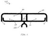
- FIG. 1is an elevational view of a cable management device 100 according to an embodiment of the invention.
- cable management device 100comprises a perimeter wall 110 defining a passageway 120 capable of receiving one or more cables (not shown in FIG. 1 ).
- cable management device 100further comprises a support piece 140 within passageway 120 that separates passageway 120 into separate passageways—passageway 121 and passageway 122 —both of which are capable of receiving a cable coupled to a power center.
- perimeter wall 110contains an opening 111 capable of admitting the cable coupled to the power center.
- opening 111can be large enough that such a cable may pass between the portions of perimeter wall 110 that surround opening 111 .
- perimeter wall 110may be flexed enough to allow the passage of a cable larger than the dimensions exhibited by opening 111 when perimeter wall 110 is in its normal, relaxed position.
- cable management device 100does not contain an opening analogous to opening 111 .
- Cable management device 100still further comprises an attachment feature 130 adjacent to perimeter wall 110 .
- attachment feature 130protrudes away from perimeter wall 110 and has a substantially semicircular shape so as to be compatible with the substantially circular shape of a typical power cord.
- Attachment feature 130like the rest of cable management device 100 , may be made of a strong, flexible material such as polypropylene or the like.
- FIGS. 2 and 3are perspective views of cable management device 100 showing alternate methods of attaching cable management device 100 to a power center 210 according to an embodiment of the invention.
- the phrase “power center” hereinincludes within its scope any electronic device that is associated with a plurality of cords or cables, whether such cords or cables are an integral part of such electronic device or whether such cords or cables may be attached to or connected with such electronic device.
- power center 210is a surge protector or other power strip having a power cord 220 .
- attachment feature 130 of cable management device 100is capable of removably engaging cable management device 100 with power center 210 (see FIG. 2 ) and with power cord 220 (see FIG. 3 ).
- attachment feature 130is shown as being engaged with an attachment slot 310 that is obscured from view by attachment feature 130 in FIG. 2 but that is visible in FIG. 3 .
- attachment feature 130is shown as being engaged with power cord 220 .
- a similar attachment slot built into other types of power centerswould facilitate attachment of cable management device 100 to those other types of power centers.
- FIG. 4is an elevational view of a cable management device 400 according to an embodiment of the invention.
- cable management device 400comprises a perimeter wall 410 defining a passageway 420 capable of receiving one or more cables (not shown in FIG. 4 ) and a support piece 440 .
- perimeter wall 410 , passageway 420 , and support piece 440can be similar to, respectively, perimeter wall 110 , passageway 120 , and support piece 140 , all of which were first shown in FIG. 1 .
- Cable management device 400further comprises an attachment feature 430 , which can be similar to attachment feature 130 that was first shown in FIG. 1 , and an attachment feature 450 adjacent to perimeter wall 410 .
- Attachment feature 430is capable of removably engaging cable management device 400 with a power cord such as power cord 220 (first shown in FIG. 2 ).
- attachment feature 430comprises an indentation in support piece 440 .
- perimeter wall 410comprises a wall section 412 and a wall section 413
- support piece 440has an end 441 and an end 442 that is located opposite end 441 .
- End 441 of support piece 440is coupled to wall section 412 and extends away from wall section 412
- end 442 of support piece 440is coupled to wall section 413 .
- attachment feature 430forms a channel or indentation in wall section 413 .
- a different way of thinking of what is depicted in FIG. 4involves considering attachment feature 430 as being a channel or indentation in support piece 440 and wall section 413 as containing a gap that allows access to attachment feature 430 .
- Attachment feature 450is coupled to wall section 412 .
- Attachment feature 450is capable of removably engaging cable management device 400 with a power center such as power center 210 (also first shown in FIG. 2 ).
- attachment feature 430comprises an indentation in perimeter wall 410 and has a substantially semicircular shape capable of engagement with a power cord.
- Attachment feature 450protrudes away from perimeter wall 410 and comprises a substantially planar portion 451 capable of engagement with a power center, as further described below.
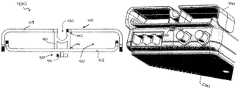
- FIG. 5is a perspective view of a portion of a power center 500 according to an embodiment of the invention.
- FIG. 6is a perspective view of a portion of power center 500 showing an engagement between power center 500 and cable management device 400 according to an embodiment of the invention.
- Power center 500comprises electrical outlets 510 , RJ-45 jacks 520 , RJ-11 jacks 530 , coaxial cable inputs 540 , and an attachment slot 550 .
- Attachment slot 550comprises an entry portal 551 and an overhang 552 , and is capable of receiving attachment feature 450 .
- substantially planar portion 451 of attachment feature 450may be inserted into entry portal 551 and slid under overhang 552 such that cable management device 400 is removably attached to power center 500 .
- FIG. 7is an elevational view of a cable management device 700 according to an embodiment of the invention.
- cable management device 700contains only a single cable passageway.
- cable management device 700comprises a perimeter wall 710 , an opening 711 in perimeter wall 710 , a passageway 720 , and an attachment feature 730 .
- perimeter wall 710 , opening 711 , passageway 720 , and attachment feature 730can be similar to, respectively, perimeter wall 110 , opening 111 , passageway 120 , and attachment feature 130 , all of which were first shown in FIG. 1 .
- FIG. 8is a perspective view of a cable management system 801 including cable management device 400 and a power center 810 according to an embodiment of the invention.
- power center 810comprises a housing 815 , a plurality of electrical outlets 816 in housing 815 , and a power cord 817 coupled to housing 815 .
- An attachment slot in housing 815is obscured by cable management device 400 but can be similar to attachment slot 310 of FIG. 3 .
- FIG. 8depicts cable management device 400 being used in a first manner to organize and manage cables 820 . More specifically, FIG. 8 depicts cable management device 400 directly engaged with power center 810 such that cables 820 are routed away from power cord 817 and toward coaxial cable inputs 540 .
- the manner of use for cable management device 400 illustrated in FIG. 8may be the most effective and sensible manner, or simply the desired manner, in which to use cable management device 400 .
- FIG. 9is a perspective view of cable management system 801 showing cable management device 400 attached in an alternate manner to power center 810 according to an embodiment of the invention.
- An attachment slot 910which was obscured from view in FIG. 8 as explained above, is visible in FIG. 9 .
- FIG. 9depicts cable management device 400 being used in a second manner to organize and manage cables 820 . More specifically, FIG. 9 depicts cable management device 400 engaged with power cord 817 of power center 810 such that cables 820 are routed toward power cord 817 .
- the manner of use for cable management device 400 illustrated in FIG. 9may be the most effective and sensible manner, or simply the desired manner, in which to use cable management device 400 .
- cable management device 400may be used in a third manner, in which cables 820 are introduced into a passageway of cable management device 400 but where cable management device 400 is neither attached to a power center nor to a power cord of the power center.
- the third manner of useis one in which cable management device 400 “floats” on cables 820 themselves, meaning cable management device 400 moves freely along the lengths of cables 820 . It will be readily apparent that cable management device 400 , as well as the other cable management devices disclosed herein, may be used at least in what have been described above as the second and third manners in connection both with power centers that have attachment slots and with those that do not.
- FIG. 10is a perspective view of a cable management system 1000 according to an embodiment of the invention.
- cable management system 1000comprises a mounting rail 1010 , a cable management device 1020 , a cable management device 1030 , and a cable management device 1040 .
- the illustrated embodiment of cable management system 1000comprises three cable management devices, in a non-illustrated embodiment, cable management system 1000 can comprise one or two cable management devices or can comprise more than three cable management devices. Also, any of the cable management devices that are part of cable management system 1000 can fit the description of any of the cable management devices described or disclosed herein.
- cable management device 1020is similar to cable management device 100 , first shown in FIG. 1
- cable management device 1030is similar to cable management device 700 , first shown in FIG. 7
- cable management device 1040is similar to cable management device 400 , first shown in FIG. 4 .
- Mounting rail 1010has a flat side 1011 that is capable of being mounted to a surface.
- flat side 1011 of mounting rail 1010can be mounted to a near a computer workstation, a desk, a home entertainment center, or the like.
- mounting rail 1010may be mounted to a surface such as those mentioned above (or another suitable surface) using adhesive, screws, a hook and loop fastener such as Velcro®, or the like. With mounting rail 1010 mounted in such a location, cable management system 1000 is in position to effectively manage and organize any cables that are in use nearby.
- one or more of cable management devices 1020 , 1030 , and 1040are capable of sliding freely along at least a portion of the length of mounting rail 1010 .
- one or more of cable management devices 1020 , 1030 , and 1040are permanently fixed to a particular location on mounting rail 1010 . It should be understood that the length of mounting rail 1010 can vary as necessary or suitable for the particular environment or application in which cable management system 1000 is used.
- embodiments and limitations disclosed hereinare not dedicated to the public under the doctrine of dedication if the embodiments and/or limitations: (1) are not expressly claimed in the claims; and (2) are or are potentially equivalents of express elements and/or limitations in the claims under the doctrine of equivalents.
Landscapes
- Engineering & Computer Science (AREA)
- Architecture (AREA)
- Civil Engineering (AREA)
- Structural Engineering (AREA)
- Installation Of Indoor Wiring (AREA)
- Details Of Connecting Devices For Male And Female Coupling (AREA)
Abstract
Description
Claims (20)
Priority Applications (3)
| Application Number | Priority Date | Filing Date | Title |
|---|---|---|---|
| US11/282,875US7361050B2 (en) | 2005-11-17 | 2005-11-17 | Cable management device for use in connection with a power center, and cable management system comprising same |
| EP06124278AEP1788683A3 (en) | 2005-11-17 | 2006-11-17 | Cable management device for use in connection with a connector device for data and power network, and cable managment system comprising same |
| AU2006241303AAU2006241303B2 (en) | 2005-11-17 | 2006-11-17 | Cable management device for use in connection with a power center, and cable management system comprising same |
Applications Claiming Priority (1)
| Application Number | Priority Date | Filing Date | Title |
|---|---|---|---|
| US11/282,875US7361050B2 (en) | 2005-11-17 | 2005-11-17 | Cable management device for use in connection with a power center, and cable management system comprising same |
Publications (2)
| Publication Number | Publication Date |
|---|---|
| US20070111585A1 US20070111585A1 (en) | 2007-05-17 |
| US7361050B2true US7361050B2 (en) | 2008-04-22 |
Family
ID=37775490
Family Applications (1)
| Application Number | Title | Priority Date | Filing Date |
|---|---|---|---|
| US11/282,875Expired - Fee RelatedUS7361050B2 (en) | 2005-11-17 | 2005-11-17 | Cable management device for use in connection with a power center, and cable management system comprising same |
Country Status (3)
| Country | Link |
|---|---|
| US (1) | US7361050B2 (en) |
| EP (1) | EP1788683A3 (en) |
| AU (1) | AU2006241303B2 (en) |
Cited By (14)
| Publication number | Priority date | Publication date | Assignee | Title |
|---|---|---|---|---|
| US20110076877A1 (en)* | 2009-09-25 | 2011-03-31 | Jeffrey Fleisig | Wall-mountable electrical power supplying device for mounting to a wall surface about a standard wall-mounted power receptacle, using a mounting bracket arranged between the housing and wall surface and an electrical power supply plug integrated with the housing |
| US20110192857A1 (en)* | 2008-12-18 | 2011-08-11 | Wayne Philip Rothbaum | Magnetically Attached Accessories (For A Case) for a Portable Electronics Device |
| US8002586B2 (en) | 2009-09-25 | 2011-08-23 | Pucline, Llc | Electrical power supplying device having a lower deck housing region for containing and concealing a plurality of electrical power adapters associated with a plurality of electrical appliances, and an upper deck housing region for supporting a ring-like power assembly having a central aperture and receiving the power plugs and/or power adapters of electrical appliances, while managing excess power cord length within a 3D volume passing through said central aperture |
| US8002587B2 (en) | 2009-09-25 | 2011-08-23 | Pucline, Llc | Ring-like electical power supplying structure for receiving the electrical power plugs of a plurality of electrical appliances and powering the same |
| US8016611B2 (en) | 2009-09-25 | 2011-09-13 | Pucline Llc | Electrical power supplying device having a ring-like structure for receiving the power plugs and/or power adapters associated with a plurality of electrical appliances, and an integrated thermal management system |
| US8159085B2 (en) | 2009-09-25 | 2012-04-17 | Pucline, Llc | Wall-mountable electrical power supplying device having a ring-like structure for receiving the power plugs and/or power adapters associated with a plurality of electrical appliances, and a housing containing and concealing the same during power supply operations |
| US8174147B2 (en) | 2009-09-25 | 2012-05-08 | Pucline, Llc | Electrical power supplying device having a ring-like power assembly for receiving electrical power plugs and/or power adapters associated with a plurality of electrical appliances, and an un-interrupted power supply (UPS) unit having a battery componenent mounted within a centrally-disposed structure passing through a central aperture in said ring-like power assembly |
| US8193658B2 (en) | 2009-09-25 | 2012-06-05 | Pucline, Llc | Electrical power supplying device having a ring-like subassembly for receiving the power plugs and/or power adapters associated with a plurality of electrical appliances, and managing excess power cord length therewithin in a concealed manner |
| US8217528B2 (en) | 2009-09-25 | 2012-07-10 | PUCline, Inc. | Electrical power supplying device having a ring-like subassembly for receiving the power plugs and/or power adapters associated with a plurality of electrical appliances, and a housing design for containing and concealing the power plug and adaptors during power supplying operations |
| US9184546B2 (en) | 2009-09-25 | 2015-11-10 | Pucline, Llc | Electrical power supplying device having a central power-hub assembly supplying electrical power to power plugs, adaptors and modules while concealed from view and managing excess power cord during power supplying operations |
| US9513682B2 (en) | 2013-07-03 | 2016-12-06 | Pucline, Llc | Transportable electrical power supplying device for storing and configuring excess power cord and sharing a multiplicity of AC and DC electrical power supplies in diverse user environments |
| US9912154B2 (en) | 2009-09-25 | 2018-03-06 | Pucline, Llc | Electrical power supplying device having a central power-receptacle assembly with a penisula-like housing structure supplying electrical power to power plugs, adaptors and modules while concealed from view during power supplying operations |
| US9927837B2 (en) | 2013-07-03 | 2018-03-27 | Pucline, Llc | Electrical power supplying system having an electrical power supplying docking station with a multi-function module for use in diverse environments |
| US11480997B1 (en)* | 2021-12-24 | 2022-10-25 | Shenzhen Okute Electronic Technology Co., Ltd. | Interface adapter |
Families Citing this family (3)
| Publication number | Priority date | Publication date | Assignee | Title |
|---|---|---|---|---|
| US7910829B2 (en)* | 2008-09-02 | 2011-03-22 | Bell'o International Corp. | Cable management system |
| CN103576265B (en)* | 2012-08-06 | 2016-04-27 | 3M创新有限公司 | Line winder |
| GB2591257B (en)* | 2020-01-22 | 2022-11-09 | Keymed Medical & Industrial Equipment Ltd | Cable management system |
Citations (7)
| Publication number | Priority date | Publication date | Assignee | Title |
|---|---|---|---|---|
| US4457571A (en)* | 1981-08-14 | 1984-07-03 | Lavine Daniel J | Retainer apparatus for electric plugs |
| US4494809A (en)* | 1983-02-15 | 1985-01-22 | Leonard Soloman | Security attachment for electrical plug |
| US5011427A (en)* | 1990-03-13 | 1991-04-30 | Martin Eugene Z | Cord protector |
| US5104335A (en)* | 1991-03-05 | 1992-04-14 | Conley Paul M | Electrical cord connector and retainer |
| US5655924A (en)* | 1996-06-10 | 1997-08-12 | The Dzyne Group, Ltd. | Electrical plug retainer system |
| US6179665B1 (en) | 1998-08-27 | 2001-01-30 | Curtis Computer Products, Inc. | Multi-function outlet strip having cable organizing features |
| US20060276077A1 (en)* | 2005-06-03 | 2006-12-07 | Belkin Corporation | Electrical connectivity system capable of being mounted to an object, and method of manufacturing same |
Family Cites Families (3)
| Publication number | Priority date | Publication date | Assignee | Title |
|---|---|---|---|---|
| DE19716695C1 (en)* | 1997-04-21 | 1998-12-10 | Kabelschlepp Gmbh | Energy chain for the stationary routing of cables |
| US7193830B2 (en)* | 2003-04-10 | 2007-03-20 | American Power Conversion Corporation | Surge suppressor |
| JP2005203178A (en)* | 2004-01-14 | 2005-07-28 | Honda Motor Co Ltd | Battery terminal connection structure |
- 2005
- 2005-11-17USUS11/282,875patent/US7361050B2/ennot_activeExpired - Fee Related
- 2006
- 2006-11-17EPEP06124278Apatent/EP1788683A3/ennot_activeWithdrawn
- 2006-11-17AUAU2006241303Apatent/AU2006241303B2/ennot_activeCeased
Patent Citations (7)
| Publication number | Priority date | Publication date | Assignee | Title |
|---|---|---|---|---|
| US4457571A (en)* | 1981-08-14 | 1984-07-03 | Lavine Daniel J | Retainer apparatus for electric plugs |
| US4494809A (en)* | 1983-02-15 | 1985-01-22 | Leonard Soloman | Security attachment for electrical plug |
| US5011427A (en)* | 1990-03-13 | 1991-04-30 | Martin Eugene Z | Cord protector |
| US5104335A (en)* | 1991-03-05 | 1992-04-14 | Conley Paul M | Electrical cord connector and retainer |
| US5655924A (en)* | 1996-06-10 | 1997-08-12 | The Dzyne Group, Ltd. | Electrical plug retainer system |
| US6179665B1 (en) | 1998-08-27 | 2001-01-30 | Curtis Computer Products, Inc. | Multi-function outlet strip having cable organizing features |
| US20060276077A1 (en)* | 2005-06-03 | 2006-12-07 | Belkin Corporation | Electrical connectivity system capable of being mounted to an object, and method of manufacturing same |
Non-Patent Citations (3)
| Title |
|---|
| Belkin 1-Outlet SurgeMaster(R) Gold; Part # F9G1030-12; http://catalog.belkin.com/IWCatProductPage.process?Merchant<SUB>-</SUB>Id=&Product<SUB>-</SUB>Id=12841; retrieved from the Internet on Nov. 18, 2005. |
| Organize-It-Online.com; Oxo Cord and Cable Clips (Set of 4); http://www.organize-it-online.com/itm<SUB>-</SUB>ggcordclips.html;retrieved from the internet on Nov. 11, 2006; 2 pages. |
| Oxo International-GoodGrips Cord & Cable Clip-4pk White; http://www.oxo.com/catalog/product<SUB>-</SUB>info.php?products<SUB>-</SUB>id=528; retrieved from the Internet on Nov. 17, 2005. |
Cited By (17)
| Publication number | Priority date | Publication date | Assignee | Title |
|---|---|---|---|---|
| US20110192857A1 (en)* | 2008-12-18 | 2011-08-11 | Wayne Philip Rothbaum | Magnetically Attached Accessories (For A Case) for a Portable Electronics Device |
| US8193658B2 (en) | 2009-09-25 | 2012-06-05 | Pucline, Llc | Electrical power supplying device having a ring-like subassembly for receiving the power plugs and/or power adapters associated with a plurality of electrical appliances, and managing excess power cord length therewithin in a concealed manner |
| US9184546B2 (en) | 2009-09-25 | 2015-11-10 | Pucline, Llc | Electrical power supplying device having a central power-hub assembly supplying electrical power to power plugs, adaptors and modules while concealed from view and managing excess power cord during power supplying operations |
| US8002587B2 (en) | 2009-09-25 | 2011-08-23 | Pucline, Llc | Ring-like electical power supplying structure for receiving the electrical power plugs of a plurality of electrical appliances and powering the same |
| US8016611B2 (en) | 2009-09-25 | 2011-09-13 | Pucline Llc | Electrical power supplying device having a ring-like structure for receiving the power plugs and/or power adapters associated with a plurality of electrical appliances, and an integrated thermal management system |
| US8026633B2 (en) | 2009-09-25 | 2011-09-27 | Pucline, Llc | Wall-mountable electrical power supplying device for mounting to a wall surface about a standard wall-mounted power receptacle, using a mounting bracket arranged between the housing and wall surface and an electrical power supply plug integrated with the housing |
| US8159085B2 (en) | 2009-09-25 | 2012-04-17 | Pucline, Llc | Wall-mountable electrical power supplying device having a ring-like structure for receiving the power plugs and/or power adapters associated with a plurality of electrical appliances, and a housing containing and concealing the same during power supply operations |
| US8002586B2 (en) | 2009-09-25 | 2011-08-23 | Pucline, Llc | Electrical power supplying device having a lower deck housing region for containing and concealing a plurality of electrical power adapters associated with a plurality of electrical appliances, and an upper deck housing region for supporting a ring-like power assembly having a central aperture and receiving the power plugs and/or power adapters of electrical appliances, while managing excess power cord length within a 3D volume passing through said central aperture |
| US8174147B2 (en) | 2009-09-25 | 2012-05-08 | Pucline, Llc | Electrical power supplying device having a ring-like power assembly for receiving electrical power plugs and/or power adapters associated with a plurality of electrical appliances, and an un-interrupted power supply (UPS) unit having a battery componenent mounted within a centrally-disposed structure passing through a central aperture in said ring-like power assembly |
| US8217528B2 (en) | 2009-09-25 | 2012-07-10 | PUCline, Inc. | Electrical power supplying device having a ring-like subassembly for receiving the power plugs and/or power adapters associated with a plurality of electrical appliances, and a housing design for containing and concealing the power plug and adaptors during power supplying operations |
| US20110076877A1 (en)* | 2009-09-25 | 2011-03-31 | Jeffrey Fleisig | Wall-mountable electrical power supplying device for mounting to a wall surface about a standard wall-mounted power receptacle, using a mounting bracket arranged between the housing and wall surface and an electrical power supply plug integrated with the housing |
| US9912154B2 (en) | 2009-09-25 | 2018-03-06 | Pucline, Llc | Electrical power supplying device having a central power-receptacle assembly with a penisula-like housing structure supplying electrical power to power plugs, adaptors and modules while concealed from view during power supplying operations |
| US9513682B2 (en) | 2013-07-03 | 2016-12-06 | Pucline, Llc | Transportable electrical power supplying device for storing and configuring excess power cord and sharing a multiplicity of AC and DC electrical power supplies in diverse user environments |
| US9927837B2 (en) | 2013-07-03 | 2018-03-27 | Pucline, Llc | Electrical power supplying system having an electrical power supplying docking station with a multi-function module for use in diverse environments |
| US11150697B2 (en) | 2013-07-03 | 2021-10-19 | Pucline Llc | Multi-function electrical power supplying station with dockable station supporting emergency lighting, portable lighting, and consumer device battery recharging modes of operation |
| US11614784B2 (en) | 2013-07-03 | 2023-03-28 | Pucline, Llc | Electrical power supplying and cord management station with dockable module supporting multiple modes of operation |
| US11480997B1 (en)* | 2021-12-24 | 2022-10-25 | Shenzhen Okute Electronic Technology Co., Ltd. | Interface adapter |
Also Published As
| Publication number | Publication date |
|---|---|
| EP1788683A3 (en) | 2012-03-21 |
| EP1788683A2 (en) | 2007-05-23 |
| AU2006241303A1 (en) | 2007-05-31 |
| AU2006241303B2 (en) | 2009-06-11 |
| US20070111585A1 (en) | 2007-05-17 |
Similar Documents
| Publication | Publication Date | Title |
|---|---|---|
| EP1788683A2 (en) | Cable management device for use in connection with a connector device for data and power network, and cable managment system comprising same | |
| EP2131464A1 (en) | In-desk USB hub and connectivity system | |
| EP1916591A1 (en) | Cable management device and method of cable management | |
| EP2197323B1 (en) | Horizontal cable manager | |
| US20160174402A1 (en) | Mounting fixture system | |
| US20170160506A1 (en) | Pivotable cover for sliding tray and sliding tray including the cover | |
| US8598462B2 (en) | Cable management apparatus | |
| US7781676B2 (en) | System and method for managing cables in a display base | |
| US20180106102A1 (en) | End caps for architectural coverings | |
| US7717738B2 (en) | Power cord management attachment for use with a power socket device | |
| CN105531879A (en) | Electrical connector for use with printed circuit boards | |
| US7459634B2 (en) | System and method for managing cables | |
| CN102193602B (en) | Server casing | |
| US7154052B2 (en) | Device plate for mounting a communications device to a raceway | |
| US20140322961A1 (en) | Connector assembly | |
| US20110244717A1 (en) | Mounting apparatus for electronic device | |
| US11223186B2 (en) | Utility conduit system | |
| US20070086153A1 (en) | Display base cable management system and method | |
| CN107078484B (en) | Adapters for use in cable channels and cable distribution systems | |
| US20070084625A1 (en) | System and method for managing cables in a display stand | |
| JP2012038323A (en) | Interface system | |
| CN202488623U (en) | Cabling rack and communication device | |
| KR200384336Y1 (en) | Wiring Duct for Desk | |
| KR20090106426A (en) | Boxed Multi-tap | |
| KR20120010291A (en) | Cable organizer |
Legal Events
| Date | Code | Title | Description |
|---|---|---|---|
| AS | Assignment | Owner name:WELLS FARGO BANK, N.A., AS ADMINISTRATIVE AGENT, C Free format text:SECURITY AGREEMENT;ASSIGNOR:BELKIN CORPORATION;REEL/FRAME:017209/0030 Effective date:20060113 Owner name:WELLS FARGO BANK, N.A., AS ADMINISTRATIVE AGENT,CA Free format text:SECURITY AGREEMENT;ASSIGNOR:BELKIN CORPORATION;REEL/FRAME:017209/0030 Effective date:20060113 | |
| AS | Assignment | Owner name:BELKIN INTERNATIONAL, INC., CALIFORNIA Free format text:ASSIGNMENT OF ASSIGNORS INTEREST;ASSIGNORS:MORI, KENNETH;WADSWORTH, JOHN;REEL/FRAME:018992/0088 Effective date:20070119 Owner name:BELKIN INTERNATIONAL, INC.,CALIFORNIA Free format text:ASSIGNMENT OF ASSIGNORS INTEREST;ASSIGNORS:MORI, KENNETH;WADSWORTH, JOHN;REEL/FRAME:018992/0088 Effective date:20070119 | |
| FPAY | Fee payment | Year of fee payment:4 | |
| AS | Assignment | Owner name:BELKIN, INC. (FORMERLY KNOWN AS BELKIN LOGISTICS, Free format text:RELEASE BY SECURED PARTY;ASSIGNOR:WELLS FARGO BANK, NATIONAL ASSOCIATION, AS ADMINISTRATIVE AGENT, L/C ISSUER AND SWING LINE LENDER;REEL/FRAME:027008/0824 Effective date:20110930 Owner name:BELKIN INTERNATIONAL, INC. (FORMERLY KNOWN AS BELK Free format text:RELEASE BY SECURED PARTY;ASSIGNOR:WELLS FARGO BANK, NATIONAL ASSOCIATION, AS ADMINISTRATIVE AGENT, L/C ISSUER AND SWING LINE LENDER;REEL/FRAME:027008/0824 Effective date:20110930 | |
| AS | Assignment | Owner name:WELLS FARGO CAPITAL FINANCE, LLC, AS AGENT, CALIFO Free format text:PATENT SECURITY AGREEMENT;ASSIGNOR:BELKIN INTERNATIONAL, INC;REEL/FRAME:027844/0525 Effective date:20120306 | |
| REMI | Maintenance fee reminder mailed | ||
| LAPS | Lapse for failure to pay maintenance fees | ||
| STCH | Information on status: patent discontinuation | Free format text:PATENT EXPIRED DUE TO NONPAYMENT OF MAINTENANCE FEES UNDER 37 CFR 1.362 | |
| FP | Lapsed due to failure to pay maintenance fee | Effective date:20160422 |