US7359610B2 - Cable manager including nestable radius limiter - Google Patents
Cable manager including nestable radius limiterDownload PDFInfo
- Publication number
- US7359610B2 US7359610B2US11/397,922US39792206AUS7359610B2US 7359610 B2US7359610 B2US 7359610B2US 39792206 AUS39792206 AUS 39792206AUS 7359610 B2US7359610 B2US 7359610B2
- Authority
- US
- United States
- Prior art keywords
- radius limiter
- bodies
- cable
- tabs
- cable radius
- Prior art date
- Legal status (The legal status is an assumption and is not a legal conclusion. Google has not performed a legal analysis and makes no representation as to the accuracy of the status listed.)
- Active
Links
Images


Classifications
- G—PHYSICS
- G02—OPTICS
- G02B—OPTICAL ELEMENTS, SYSTEMS OR APPARATUS
- G02B6/00—Light guides; Structural details of arrangements comprising light guides and other optical elements, e.g. couplings
- G02B6/44—Mechanical structures for providing tensile strength and external protection for fibres, e.g. optical transmission cables
- G02B6/4439—Auxiliary devices
- G02B6/444—Systems or boxes with surplus lengths
- G02B6/4452—Distribution frames
- G02B6/44524—Distribution frames with frame parts or auxiliary devices mounted on the frame and collectively not covering a whole width of the frame or rack
- G—PHYSICS
- G02—OPTICS
- G02B—OPTICAL ELEMENTS, SYSTEMS OR APPARATUS
- G02B6/00—Light guides; Structural details of arrangements comprising light guides and other optical elements, e.g. couplings
- G02B6/44—Mechanical structures for providing tensile strength and external protection for fibres, e.g. optical transmission cables
- G02B6/4439—Auxiliary devices
- G02B6/444—Systems or boxes with surplus lengths
- G02B6/44528—Patch-cords; Connector arrangements in the system or in the box
- G—PHYSICS
- G02—OPTICS
- G02B—OPTICAL ELEMENTS, SYSTEMS OR APPARATUS
- G02B6/00—Light guides; Structural details of arrangements comprising light guides and other optical elements, e.g. couplings
- G02B6/44—Mechanical structures for providing tensile strength and external protection for fibres, e.g. optical transmission cables
- G02B6/4439—Auxiliary devices
- G02B6/4459—Ducts; Conduits; Hollow tubes for air blown fibres
Definitions
- the present inventionrelates generally to devices and methods for enhancing cable management of a telecommunications system. More particularly, the present invention relates to a radius limiter arrangement for use in telecommunications systems.
- Telecommunications systemscommonly include cables (e.g., fiber optic cables or copper twisted pair cables) for interconnecting pieces of telecommunications equipment.
- Telecommunication rackstypically hold a variety of different pieces of telecommunications equipment. Often thousands of cables are used to interconnect the various pieces of telecommunications equipment mounted on the racks.
- Cable managementinvolves organizing cables so that the cables run or lie in an orderly manner. Because telecommunication systems often have different cable routing requirements, adaptability of the devices used to manage and organize cables is desirable. Cable management also involves preventing damage to the cables, such as unnecessary or excessive displacement of fiber optic cables. Unnecessary or excessive bending can damage cables. For example, the bending of the fibers can cause attenuation and loss of signal strength, which can even result in the fiber breaking and a complete loss of signal transmission through the fiber.
- cable management improvementhas been sought, generally to efficiently and effectively manage cables by providing a device that prevents cable damage and is also adaptable to a variety of telecommunications applications.
- One aspect of the present inventionrelates to a cable radius limiter having mounting structure and cable retaining structure arranged such that the limiter can be operably oriented in both a first mounting orientation and a second mounting orientation.
- Another aspect of the present inventionrelates to a cable radius limiter arrangement for managing cable of a telecommunications system.
- the arrangementincludes two cable radius limiters mounted back to back to form a cable spool.
- FIG. 1is a front perspective view of a cable management panel including a plurality of radius limiters in a stacked arrangement in a first orientation.
- FIG. 2is a perspective view of one the radius limiters in the panel of FIG. 1 .
- FIG. 3is a side view of the radius limiter of FIG. 2 .
- FIG. 4is a first end view of the radius limiter of FIG. 2 .
- FIG. 5is an opposite end view to the end view of FIG. 4 of the radius limiter of FIG. 2 .
- FIG. 6is a top view of the radius limiter of FIG. 2 .
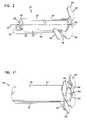
- FIG. 7is an end view of the panel of FIG. 1 .
- FIG. 8is a side view of the radius limiter of FIGS. 2-6 , shown in an opposite orientation to the orientation shown in FIGS. 2-6 .
- FIG. 9is a front perspective view of a cable management panel including a plurality of the radius limiters of FIG. 8 in a stacked arrangement in the opposite orientation.
- FIG. 10shows two radius limiters positioned back to back in order to assemble a cable management spool.
- FIG. 11is a perspective view showing the cable management spool formed by mounting the two radius limiters back to back as shown in FIG. 10 .
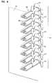
- FIG. 12is a front perspective view of a cable management panel including similar stacked arrangements to the arrangements of FIGS. 1 and 9 , and one cable management spool of FIG. 11 .
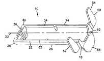
- FIG. 1illustrates one embodiment of a radius limiter 10 for use in managing telecommunications cables, including fiber optic cables.
- a plurality of radius limiters 10can be arranged in a stack 12 to form a cable management panel 14 for managing a plurality of fiber optic cables.
- radius limiter 10includes a body 16 having a front 18 and a rear 20 .
- Body 16has a first side 22 and an opposite second side 24 .
- a first surface 26extends from first side 22 to second side 24 .
- first surface 26is generally curved in a semi-circular shape extending between front 18 and rear 20 .
- Second surface 28also extends from first side 22 to second side 24 and defines a cavity.
- Body 16defines a longitudinal axis 23 extending between front 18 and rear 20 .
- First surface 26extends from front 18 to rear 20 to define a bend radius protection feature for cables laid across radius limiter 10 in a direction generally transverse to axis 23 .
- first surface 26is defined by a radius r.
- an edge 30 of rear 20 , and edges 32 , 34 of sides 22 , 24define a planar shape to a base 40 of radius limiter 10 .
- Radius limiter 10includes mounting structure 36 for mounting radius limiter 10 to a panel or other surface.
- mounting structure 36includes one or more holes 38 adjacent rear 20 of body 16 . Holes 38 can receive fasteners for fastening rear 20 to a panel element 42 .
- Radius limiter 10includes cable retaining structure 50 adjacent to front 18 for retaining cables adjacent to first surface 26 .
- cable retaining structureincludes first and second tabs 52 , 54 extending in a first direction, and a third tab 56 extending in an opposite direction.
- Third tab 56is generally centered relative to first surface.
- First and second tabs 52 , 54are generally positioned adjacent to first and second sides 22 , 24 , respectively.
- tabs 52 , 54 , 56form distal ends of a front plate 51 .
- Distal tips 52 a , 54 aare on one side of a plane defined by base 40 , and distal tip 56 a is on an opposite side (see FIG. 4 , for example).
- Front 18 of body 16 of radius limiter 10defines a front opening 62 which provides access to rear 20 , such as for accessing fasteners positioned in holes 38 to mount or remove radius limiter with respect to panel element 42 .
- Other methods of connecting radius limiter 10 to panel element 42are anticipated, including snaps.
- the cable retaining structures 50are shown wherein tabs 52 , 54 of one radius limiter 10 nests into recesses 68 formed by the adjacent radius limiter 10 on opposite sides of third tab 56 .
- cablesare passed through gaps 70 .
- Tabs 52 , 54 , 56keep other cables in place on radius limiters 10 when other cables are accessed.
- radius limiter 10can be used where first surface 26 faces vertically upwardly, instead of facing vertically downwardly as shown in panel 14 of FIG. 1 .
- FIG. 9shows a stack 72 of radius limiters 10 on a cable management panel 74 wherein the first surfaces 26 face vertically upwardly. Radius limiters 10 can also be used where first surfaces 26 face other directions including horizontally.
- FIG. 10two radius limiters 10 can be nested together back to back, i.e. where second surfaces 28 face each other.
- FIG. 11shows the resulting combination of two radius limiters 10 nested back to back to form a spool 76 wherein first surfaces 26 allow a cable to be wrapped completely around the resulting structure.
- first and second tabs 52 , 54are offset relative to one another as is visible in FIGS. 3 and 6 .
- tabs 52 , 54are each offset from tab 56 , one forwardly and one rearwardly.
- Front openings 62 of each radius limitercooperate to form an opening 82 which is useful for accessing holes 38 to mount or remove each radius limiter 10 from the panel element.
- a cable management panel 104including a first stack 106 of radius limiters 10 with the first surfaces 26 facing upwardly.
- a second stack 108 of radius limiters 10is provided with the first surfaces 26 facing downwardly.
- Two radius limiters 10are mounted back to back to form a spool 76 . Cables extending to cable termination area 120 can be managed by spool 76 , one or more selected radius limiters 10 in second stack 108 , and one or more selected radius limiters 10 in first stack 106 .
Landscapes
- Physics & Mathematics (AREA)
- General Physics & Mathematics (AREA)
- Optics & Photonics (AREA)
- Installation Of Indoor Wiring (AREA)
- Storage Of Web-Like Or Filamentary Materials (AREA)
- Laying Of Electric Cables Or Lines Outside (AREA)
Abstract
Description
Claims (12)
Priority Applications (6)
| Application Number | Priority Date | Filing Date | Title |
|---|---|---|---|
| US11/397,922US7359610B2 (en) | 2006-04-03 | 2006-04-03 | Cable manager including nestable radius limiter |
| BRPI0710045-0ABRPI0710045A2 (en) | 2006-04-03 | 2007-04-02 | cable manager including nestable radius limiter |
| PCT/US2007/008156WO2007120508A2 (en) | 2006-04-03 | 2007-04-02 | Cable manager including nestable radius limiter |
| EP07754648AEP2002299A2 (en) | 2006-04-03 | 2007-04-02 | Cable manager including nestable radius limiter |
| US12/072,085US7421183B2 (en) | 2006-04-03 | 2008-02-22 | Cable manager including nestable radius limiter |
| US12/231,320US7565051B2 (en) | 2006-04-03 | 2008-08-27 | Cable manager including nestable radius limiter |
Applications Claiming Priority (1)
| Application Number | Priority Date | Filing Date | Title |
|---|---|---|---|
| US11/397,922US7359610B2 (en) | 2006-04-03 | 2006-04-03 | Cable manager including nestable radius limiter |
Related Child Applications (1)
| Application Number | Title | Priority Date | Filing Date |
|---|---|---|---|
| US12/072,085ContinuationUS7421183B2 (en) | 2006-04-03 | 2008-02-22 | Cable manager including nestable radius limiter |
Publications (2)
| Publication Number | Publication Date |
|---|---|
| US20070230887A1 US20070230887A1 (en) | 2007-10-04 |
| US7359610B2true US7359610B2 (en) | 2008-04-15 |
Family
ID=38476989
Family Applications (3)
| Application Number | Title | Priority Date | Filing Date |
|---|---|---|---|
| US11/397,922ActiveUS7359610B2 (en) | 2006-04-03 | 2006-04-03 | Cable manager including nestable radius limiter |
| US12/072,085ActiveUS7421183B2 (en) | 2006-04-03 | 2008-02-22 | Cable manager including nestable radius limiter |
| US12/231,320Expired - Fee RelatedUS7565051B2 (en) | 2006-04-03 | 2008-08-27 | Cable manager including nestable radius limiter |
Family Applications After (2)
| Application Number | Title | Priority Date | Filing Date |
|---|---|---|---|
| US12/072,085ActiveUS7421183B2 (en) | 2006-04-03 | 2008-02-22 | Cable manager including nestable radius limiter |
| US12/231,320Expired - Fee RelatedUS7565051B2 (en) | 2006-04-03 | 2008-08-27 | Cable manager including nestable radius limiter |
Country Status (4)
| Country | Link |
|---|---|
| US (3) | US7359610B2 (en) |
| EP (1) | EP2002299A2 (en) |
| BR (1) | BRPI0710045A2 (en) |
| WO (1) | WO2007120508A2 (en) |
Cited By (9)
| Publication number | Priority date | Publication date | Assignee | Title |
|---|---|---|---|---|
| US20070123095A1 (en)* | 2005-11-30 | 2007-05-31 | Jim Hybiske | Cable organizer |
| US20080145014A1 (en)* | 2006-04-03 | 2008-06-19 | Adc Telecommunications, Inc. | Cable manager including nestable radius limiter |
| USD589782S1 (en)* | 2008-01-25 | 2009-04-07 | Futurewei Technologies, Inc. | Horizontal and vertical cable holder |
| US20090101404A1 (en)* | 2007-10-23 | 2009-04-23 | Slam Brands, Inc. | Cable management apparatuses and systems |
| US20090103879A1 (en)* | 2007-10-22 | 2009-04-23 | Adc Telecommunications, Inc. | Fiber Distribution Hub |
| US20110058785A1 (en)* | 2009-09-04 | 2011-03-10 | Adc Telecommunications, Inc. | Pedestal terminal with swing frame |
| USRE46525E1 (en) | 2007-01-12 | 2017-08-29 | Corning Optical Communications LLC | Fiber optic local convergence points for multiple dwelling units |
| US20180090244A1 (en)* | 2016-09-23 | 2018-03-29 | Woodstream Corporation | Stackable electric fence wire insulators |
| US11268636B2 (en)* | 2016-07-26 | 2022-03-08 | Chatsworth Products, Inc. | Features for cable managers and other electronic equipment structures |
Families Citing this family (52)
| Publication number | Priority date | Publication date | Assignee | Title |
|---|---|---|---|---|
| EP2620510B2 (en) | 2005-06-15 | 2020-02-19 | Complete Genomics Inc. | Single molecule arrays for genetic and chemical analysis |
| SE535066C2 (en) | 2008-01-07 | 2012-04-03 | Chatsworth Prod Inc | Vertical cable management device |
| US8263867B2 (en) | 2008-01-07 | 2012-09-11 | Chatsworth Products, Inc. | Cable management accessories |
| US11294136B2 (en) | 2008-08-29 | 2022-04-05 | Corning Optical Communications LLC | High density and bandwidth fiber optic apparatuses and related equipment and methods |
| US8452148B2 (en) | 2008-08-29 | 2013-05-28 | Corning Cable Systems Llc | Independently translatable modules and fiber optic equipment trays in fiber optic equipment |
| US7856166B2 (en) | 2008-09-02 | 2010-12-21 | Corning Cable Systems Llc | High-density patch-panel assemblies for optical fiber telecommunications |
| EP2221932B1 (en) | 2009-02-24 | 2011-11-16 | CCS Technology Inc. | Holding device for a cable or an assembly for use with a cable |
| US8699838B2 (en) | 2009-05-14 | 2014-04-15 | Ccs Technology, Inc. | Fiber optic furcation module |
| US9075216B2 (en) | 2009-05-21 | 2015-07-07 | Corning Cable Systems Llc | Fiber optic housings configured to accommodate fiber optic modules/cassettes and fiber optic panels, and related components and methods |
| US8538226B2 (en) | 2009-05-21 | 2013-09-17 | Corning Cable Systems Llc | Fiber optic equipment guides and rails configured with stopping position(s), and related equipment and methods |
| US8712206B2 (en) | 2009-06-19 | 2014-04-29 | Corning Cable Systems Llc | High-density fiber optic modules and module housings and related equipment |
| WO2010148325A1 (en) | 2009-06-19 | 2010-12-23 | Corning Cable Systems Llc | High fiber optic cable packing density apparatus |
| EP2443497B1 (en) | 2009-06-19 | 2020-03-04 | Corning Cable Systems LLC | High density and bandwidth fiber optic apparatus |
| US8625950B2 (en) | 2009-12-18 | 2014-01-07 | Corning Cable Systems Llc | Rotary locking apparatus for fiber optic equipment trays and related methods |
| USD653623S1 (en) | 2010-01-16 | 2012-02-07 | Chatsworth Products, Inc. | Raceway for cable management |
| USD637065S1 (en)* | 2010-01-16 | 2011-05-03 | Chatsworth Products, Inc. | Cable guide projection |
| USD651570S1 (en) | 2010-01-16 | 2012-01-03 | Chatsworth Products, Inc. | Raceway for cable management |
| USD635935S1 (en) | 2010-01-16 | 2011-04-12 | Chatsworth Products, Inc. | Cover for cable management raceway |
| US8558113B2 (en) | 2010-01-17 | 2013-10-15 | Chatsworth Products, Inc. | Vertical cable manager |
| US8710369B2 (en) | 2010-01-17 | 2014-04-29 | Chatsworth Products, Inc. | Horizontal cable manager |
| US8992099B2 (en) | 2010-02-04 | 2015-03-31 | Corning Cable Systems Llc | Optical interface cards, assemblies, and related methods, suited for installation and use in antenna system equipment |
| US8913866B2 (en) | 2010-03-26 | 2014-12-16 | Corning Cable Systems Llc | Movable adapter panel |
| CA2796221C (en) | 2010-04-16 | 2018-02-13 | Ccs Technology, Inc. | Sealing and strain relief device for data cables |
| EP2381284B1 (en) | 2010-04-23 | 2014-12-31 | CCS Technology Inc. | Under floor fiber optic distribution device |
| US9519118B2 (en) | 2010-04-30 | 2016-12-13 | Corning Optical Communications LLC | Removable fiber management sections for fiber optic housings, and related components and methods |
| US8660397B2 (en) | 2010-04-30 | 2014-02-25 | Corning Cable Systems Llc | Multi-layer module |
| US9632270B2 (en) | 2010-04-30 | 2017-04-25 | Corning Optical Communications LLC | Fiber optic housings configured for tool-less assembly, and related components and methods |
| US8705926B2 (en) | 2010-04-30 | 2014-04-22 | Corning Optical Communications LLC | Fiber optic housings having a removable top, and related components and methods |
| US8879881B2 (en) | 2010-04-30 | 2014-11-04 | Corning Cable Systems Llc | Rotatable routing guide and assembly |
| US9720195B2 (en) | 2010-04-30 | 2017-08-01 | Corning Optical Communications LLC | Apparatuses and related components and methods for attachment and release of fiber optic housings to and from an equipment rack |
| US9075217B2 (en) | 2010-04-30 | 2015-07-07 | Corning Cable Systems Llc | Apparatuses and related components and methods for expanding capacity of fiber optic housings |
| USD629289S1 (en) | 2010-06-29 | 2010-12-21 | Chatsworth Products, Inc. | Cable guide projection with boss |
| USD640528S1 (en) | 2010-06-29 | 2011-06-28 | Chatsworth Products, Inc. | Cable guide projection with boss |
| USD637066S1 (en)* | 2010-06-29 | 2011-05-03 | Chatsworth Products, Inc. | Cable guide projection |
| US8718436B2 (en) | 2010-08-30 | 2014-05-06 | Corning Cable Systems Llc | Methods, apparatuses for providing secure fiber optic connections |
| US9279951B2 (en) | 2010-10-27 | 2016-03-08 | Corning Cable Systems Llc | Fiber optic module for limited space applications having a partially sealed module sub-assembly |
| US9116324B2 (en) | 2010-10-29 | 2015-08-25 | Corning Cable Systems Llc | Stacked fiber optic modules and fiber optic equipment configured to support stacked fiber optic modules |
| US8662760B2 (en) | 2010-10-29 | 2014-03-04 | Corning Cable Systems Llc | Fiber optic connector employing optical fiber guide member |
| CA2819235C (en) | 2010-11-30 | 2018-01-16 | Corning Cable Systems Llc | Fiber device holder and strain relief device |
| WO2012106510A2 (en) | 2011-02-02 | 2012-08-09 | Corning Cable Systems Llc | Dense fiber optic connector assemblies and related connectors and cables suitable for establishing optical connections for optical backplanes in equipment racks |
| US8431823B2 (en)* | 2011-03-01 | 2013-04-30 | Dell Products L.P. | Cable management and identification device |
| CN102684113A (en)* | 2011-03-09 | 2012-09-19 | 鸿富锦精密工业(深圳)有限公司 | Cable fixing device |
| US9008485B2 (en) | 2011-05-09 | 2015-04-14 | Corning Cable Systems Llc | Attachment mechanisms employed to attach a rear housing section to a fiber optic housing, and related assemblies and methods |
| AU2012275598A1 (en) | 2011-06-30 | 2014-01-16 | Corning Optical Communications LLC | Fiber optic equipment assemblies employing non-U-width-sized housings and related methods |
| US8953924B2 (en) | 2011-09-02 | 2015-02-10 | Corning Cable Systems Llc | Removable strain relief brackets for securing fiber optic cables and/or optical fibers to fiber optic equipment, and related assemblies and methods |
| US9038832B2 (en) | 2011-11-30 | 2015-05-26 | Corning Cable Systems Llc | Adapter panel support assembly |
| US9250409B2 (en) | 2012-07-02 | 2016-02-02 | Corning Cable Systems Llc | Fiber-optic-module trays and drawers for fiber-optic equipment |
| US9042702B2 (en) | 2012-09-18 | 2015-05-26 | Corning Cable Systems Llc | Platforms and systems for fiber optic cable attachment |
| ES2551077T3 (en) | 2012-10-26 | 2015-11-16 | Ccs Technology, Inc. | Fiber optic management unit and fiber optic distribution device |
| US9140871B2 (en)* | 2012-12-11 | 2015-09-22 | Christie Digital Systems Usa, Inc. | Optical fiber carrier |
| US8985862B2 (en) | 2013-02-28 | 2015-03-24 | Corning Cable Systems Llc | High-density multi-fiber adapter housings |
| JP6776726B2 (en)* | 2016-08-24 | 2020-10-28 | 富士通株式会社 | Cable accommodation mechanism and electronic equipment |
Citations (7)
| Publication number | Priority date | Publication date | Assignee | Title |
|---|---|---|---|---|
| US20020097973A1 (en) | 2001-01-25 | 2002-07-25 | Petri Hector D. | Fiber optic cable guide |
| US6438310B1 (en)* | 2000-01-24 | 2002-08-20 | Adc Telecommunications, Inc. | Cable management panel with sliding drawer |
| US6468112B1 (en) | 1999-01-11 | 2002-10-22 | Adc Telecommunications, Inc. | Vertical cable management system with ribcage structure |
| US20020197044A1 (en) | 2001-06-25 | 2002-12-26 | Daoud Bassel Hage | Fiber-optic cable routing and bend limiting device |
| US6532332B2 (en) | 2001-02-15 | 2003-03-11 | Adc Telecommunications, Inc. | Cable guide for fiber termination block |
| US20050281256A1 (en) | 2004-06-21 | 2005-12-22 | Pekka Taipale | Data transmission in communication system |
| US7059895B2 (en)* | 2004-09-24 | 2006-06-13 | Ortronics, Inc. | Work station outlet for behind-the-wall cable management |
Family Cites Families (14)
| Publication number | Priority date | Publication date | Assignee | Title |
|---|---|---|---|---|
| FR2573544B1 (en)* | 1984-11-20 | 1987-04-24 | Mars Actel | OPTICAL FIBER CONNECTION SUPPORT |
| US4792203A (en)* | 1985-09-17 | 1988-12-20 | Adc Telecommunications, Inc. | Optical fiber distribution apparatus |
| US5066149A (en)* | 1990-09-11 | 1991-11-19 | Adc Telecommunications, Inc. | Splice tray with slack take-up |
| US5659650A (en)* | 1995-09-26 | 1997-08-19 | Lucent Technologies Inc. | Hinged faceplate |
| US5987207A (en)* | 1997-06-27 | 1999-11-16 | Siecor Corporation | Fiber organizer |
| US6263141B1 (en)* | 1998-09-09 | 2001-07-17 | Adc Telecommunications, Inc. | Optical fiber cable management device including storage tray |
| US6301424B1 (en)* | 2000-04-13 | 2001-10-09 | Lucent Technologies Inc. | Distribution frame cable routing apparatus |
| US6819857B2 (en)* | 2001-10-12 | 2004-11-16 | Adc Telecommunications, Inc. | Rotating vertical fiber tray and methods |
| US6748155B2 (en)* | 2002-07-22 | 2004-06-08 | Adc Telecommunications, Inc. | Fiber management drawer and sliding cable slack limiter |
| US6865331B2 (en)* | 2003-01-15 | 2005-03-08 | Adc Telecommunications, Inc. | Rotating radius limiter for cable management panel and methods |
| US7171099B2 (en)* | 2003-07-31 | 2007-01-30 | Adc Telecommunications, Inc. | Slide arrangement for cable drawer |
| US7218827B2 (en)* | 2004-06-18 | 2007-05-15 | Adc Telecommunications, Inc. | Multi-position fiber optic connector holder and method |
| US7171100B2 (en)* | 2004-11-03 | 2007-01-30 | Adc Telecommunications, Inc. | Optical fiber slack storage tray for distribution cabinet |
| US7359610B2 (en)* | 2006-04-03 | 2008-04-15 | Adc Telecommunications, Inc. | Cable manager including nestable radius limiter |
- 2006
- 2006-04-03USUS11/397,922patent/US7359610B2/enactiveActive
- 2007
- 2007-04-02BRBRPI0710045-0Apatent/BRPI0710045A2/ennot_activeApplication Discontinuation
- 2007-04-02WOPCT/US2007/008156patent/WO2007120508A2/enactiveApplication Filing
- 2007-04-02EPEP07754648Apatent/EP2002299A2/ennot_activeWithdrawn
- 2008
- 2008-02-22USUS12/072,085patent/US7421183B2/enactiveActive
- 2008-08-27USUS12/231,320patent/US7565051B2/ennot_activeExpired - Fee Related
Patent Citations (8)
| Publication number | Priority date | Publication date | Assignee | Title |
|---|---|---|---|---|
| US6468112B1 (en) | 1999-01-11 | 2002-10-22 | Adc Telecommunications, Inc. | Vertical cable management system with ribcage structure |
| US20030119385A1 (en) | 1999-01-11 | 2003-06-26 | Elliot Douglas G. | Vertical cable management system with ribcage structure |
| US6438310B1 (en)* | 2000-01-24 | 2002-08-20 | Adc Telecommunications, Inc. | Cable management panel with sliding drawer |
| US20020097973A1 (en) | 2001-01-25 | 2002-07-25 | Petri Hector D. | Fiber optic cable guide |
| US6532332B2 (en) | 2001-02-15 | 2003-03-11 | Adc Telecommunications, Inc. | Cable guide for fiber termination block |
| US20020197044A1 (en) | 2001-06-25 | 2002-12-26 | Daoud Bassel Hage | Fiber-optic cable routing and bend limiting device |
| US20050281256A1 (en) | 2004-06-21 | 2005-12-22 | Pekka Taipale | Data transmission in communication system |
| US7059895B2 (en)* | 2004-09-24 | 2006-06-13 | Ortronics, Inc. | Work station outlet for behind-the-wall cable management |
Non-Patent Citations (2)
| Title |
|---|
| U.S. Appl. No. 11/069,886, filed Feb. 28, 2005, 18 pages (admitted to be prior art as of the filing date Apr. 3, 2006). |
| Value-Added Module System, ADC Telecommunications, 4 pages, (Jun. 1998). |
Cited By (32)
| Publication number | Priority date | Publication date | Assignee | Title |
|---|---|---|---|---|
| US20090120683A1 (en)* | 2005-11-30 | 2009-05-14 | Jim Hybiske | Cable organizer |
| US20070123095A1 (en)* | 2005-11-30 | 2007-05-31 | Jim Hybiske | Cable organizer |
| US7888608B2 (en) | 2005-11-30 | 2011-02-15 | Jim Hybiske | Cable organizer |
| US7491903B2 (en)* | 2005-11-30 | 2009-02-17 | Jim Hybiske | Cable organizer |
| US7565051B2 (en) | 2006-04-03 | 2009-07-21 | Adc Telecommunications, Inc. | Cable manager including nestable radius limiter |
| US20090067801A1 (en)* | 2006-04-03 | 2009-03-12 | Adc Telecommunications, Inc. | Cable Manager including nestable radius limiter |
| US7421183B2 (en) | 2006-04-03 | 2008-09-02 | Adc Telecommunications, Inc. | Cable manager including nestable radius limiter |
| US20080145014A1 (en)* | 2006-04-03 | 2008-06-19 | Adc Telecommunications, Inc. | Cable manager including nestable radius limiter |
| USRE50042E1 (en) | 2007-01-12 | 2024-07-16 | Corning Optical Communications LLC | Fiber optic local convergence points for multiple dwelling units |
| USRE48937E1 (en) | 2007-01-12 | 2022-02-22 | Corning Optical Communications LLC | Fiber optic local convergence points for multiple dwelling units |
| USRE48082E1 (en) | 2007-01-12 | 2020-07-07 | Corning Optical Communications LLP | Fiber optic local convergence points for multiple dwelling units |
| USRE46701E1 (en) | 2007-01-12 | 2018-02-06 | Corning Cable Systems Llc | Fiber optic local convergence points for multiple dwelling units |
| USRE46525E1 (en) | 2007-01-12 | 2017-08-29 | Corning Optical Communications LLC | Fiber optic local convergence points for multiple dwelling units |
| US8032002B2 (en) | 2007-10-22 | 2011-10-04 | Adc Telecommunications, Inc. | Fiber distribution hub |
| US20090103879A1 (en)* | 2007-10-22 | 2009-04-23 | Adc Telecommunications, Inc. | Fiber Distribution Hub |
| US20100290753A1 (en)* | 2007-10-22 | 2010-11-18 | Adc Telecommunications, Inc. | Fiber distribution hub |
| US7720344B2 (en)* | 2007-10-22 | 2010-05-18 | Adc Telecommunications, Inc. | Fiber distribution hub |
| US20090101404A1 (en)* | 2007-10-23 | 2009-04-23 | Slam Brands, Inc. | Cable management apparatuses and systems |
| US7825337B2 (en)* | 2007-10-23 | 2010-11-02 | Slam Brands, Inc. | Cable management apparatuses and systems |
| USD598275S1 (en) | 2008-01-25 | 2009-08-18 | Futurewei Technologies, Inc. | Portion of a horizontal and vertical cable holder |
| USD589782S1 (en)* | 2008-01-25 | 2009-04-07 | Futurewei Technologies, Inc. | Horizontal and vertical cable holder |
| US8606067B2 (en) | 2009-09-04 | 2013-12-10 | Adc Telecommunications, Inc. | Pedestal terminal with swing frame |
| US20110058785A1 (en)* | 2009-09-04 | 2011-03-10 | Adc Telecommunications, Inc. | Pedestal terminal with swing frame |
| US11619328B2 (en) | 2016-07-26 | 2023-04-04 | Chatsworth Products, Inc. | Method of adapting electronic equipment structure for cable management |
| US11268636B2 (en)* | 2016-07-26 | 2022-03-08 | Chatsworth Products, Inc. | Features for cable managers and other electronic equipment structures |
| US11493151B2 (en) | 2016-07-26 | 2022-11-08 | Chatsworth Products, Inc. | Features for cable managers and other electronic equipment structures |
| US11644126B2 (en) | 2016-07-26 | 2023-05-09 | Chatsworth Products, Inc. | Method of installing half-spool accessory in a cable manager |
| US11644125B2 (en) | 2016-07-26 | 2023-05-09 | Chatsworth Products, Inc. | Method of installing cable finger accessory in a cable manager |
| US11815197B2 (en) | 2016-07-26 | 2023-11-14 | Chatsworth Products, Inc. | Features for cable managers and other electronic equipment structures |
| US12135103B2 (en) | 2016-07-26 | 2024-11-05 | Chatsworth Products, Inc. | Features for cable managers and other electronic equipment structures |
| US9934890B1 (en)* | 2016-09-23 | 2018-04-03 | Woodstream Corporation | Stackable electric fence wire insulators |
| US20180090244A1 (en)* | 2016-09-23 | 2018-03-29 | Woodstream Corporation | Stackable electric fence wire insulators |
Also Published As
| Publication number | Publication date |
|---|---|
| BRPI0710045A2 (en) | 2011-08-09 |
| US20070230887A1 (en) | 2007-10-04 |
| WO2007120508A2 (en) | 2007-10-25 |
| WO2007120508A3 (en) | 2008-01-24 |
| US20090067801A1 (en) | 2009-03-12 |
| US7565051B2 (en) | 2009-07-21 |
| US20080145014A1 (en) | 2008-06-19 |
| EP2002299A2 (en) | 2008-12-17 |
| US7421183B2 (en) | 2008-09-02 |
Similar Documents
| Publication | Publication Date | Title |
|---|---|---|
| US7359610B2 (en) | Cable manager including nestable radius limiter | |
| US6974348B2 (en) | High-density multi-port-module patch panel system | |
| US8899424B2 (en) | Cable management assembly, system and method | |
| US8428418B2 (en) | Fiber optic adapter plate and cassette | |
| US7978951B2 (en) | Bulkhead with angled openings and method | |
| US7207835B2 (en) | Angled patch panel assembly | |
| US7083051B2 (en) | Cable management assembly, system and method | |
| US8649648B2 (en) | Fiber optic adapter cassette and panel | |
| US8600208B2 (en) | Fiber optic telecommunications module | |
| CA2714849C (en) | Vertical cable management system with ribcage structure | |
| US8221169B2 (en) | Fanning module, fanning strip, and cable management panel | |
| US7760985B2 (en) | Radius limiter and arrangement | |
| US8670644B2 (en) | Manifold for managing fiber optic cable and structures and systems therefor | |
| US7319804B2 (en) | Radius limiter and arrangement | |
| US20100316345A1 (en) | Fiber optic panel and method | |
| WO2015054221A1 (en) | Modular break-out for cable assembly |
Legal Events
| Date | Code | Title | Description |
|---|---|---|---|
| AS | Assignment | Owner name:ADC TELECOMMUNICATIONS, INC., MINNESOTA Free format text:ASSIGNMENT OF ASSIGNORS INTEREST;ASSIGNOR:VONGSENG, SOUTSADA;REEL/FRAME:018027/0587 Effective date:20060620 | |
| STCF | Information on status: patent grant | Free format text:PATENTED CASE | |
| FPAY | Fee payment | Year of fee payment:4 | |
| AS | Assignment | Owner name:TYCO ELECTRONICS SERVICES GMBH, SWITZERLAND Free format text:ASSIGNMENT OF ASSIGNORS INTEREST;ASSIGNOR:ADC TELECOMMUNICATIONS, INC.;REEL/FRAME:036060/0174 Effective date:20110930 | |
| FPAY | Fee payment | Year of fee payment:8 | |
| AS | Assignment | Owner name:COMMSCOPE EMEA LIMITED, IRELAND Free format text:ASSIGNMENT OF ASSIGNORS INTEREST;ASSIGNOR:TYCO ELECTRONICS SERVICES GMBH;REEL/FRAME:036956/0001 Effective date:20150828 | |
| AS | Assignment | Owner name:COMMSCOPE TECHNOLOGIES LLC, NORTH CAROLINA Free format text:ASSIGNMENT OF ASSIGNORS INTEREST;ASSIGNOR:COMMSCOPE EMEA LIMITED;REEL/FRAME:037012/0001 Effective date:20150828 | |
| AS | Assignment | Owner name:JPMORGAN CHASE BANK, N.A., AS COLLATERAL AGENT, ILLINOIS Free format text:PATENT SECURITY AGREEMENT (TERM);ASSIGNOR:COMMSCOPE TECHNOLOGIES LLC;REEL/FRAME:037513/0709 Effective date:20151220 Owner name:JPMORGAN CHASE BANK, N.A., AS COLLATERAL AGENT, ILLINOIS Free format text:PATENT SECURITY AGREEMENT (ABL);ASSIGNOR:COMMSCOPE TECHNOLOGIES LLC;REEL/FRAME:037514/0196 Effective date:20151220 Owner name:JPMORGAN CHASE BANK, N.A., AS COLLATERAL AGENT, IL Free format text:PATENT SECURITY AGREEMENT (ABL);ASSIGNOR:COMMSCOPE TECHNOLOGIES LLC;REEL/FRAME:037514/0196 Effective date:20151220 Owner name:JPMORGAN CHASE BANK, N.A., AS COLLATERAL AGENT, IL Free format text:PATENT SECURITY AGREEMENT (TERM);ASSIGNOR:COMMSCOPE TECHNOLOGIES LLC;REEL/FRAME:037513/0709 Effective date:20151220 | |
| AS | Assignment | Owner name:COMMSCOPE TECHNOLOGIES LLC, NORTH CAROLINA Free format text:RELEASE BY SECURED PARTY;ASSIGNOR:JPMORGAN CHASE BANK, N.A.;REEL/FRAME:048840/0001 Effective date:20190404 Owner name:ANDREW LLC, NORTH CAROLINA Free format text:RELEASE BY SECURED PARTY;ASSIGNOR:JPMORGAN CHASE BANK, N.A.;REEL/FRAME:048840/0001 Effective date:20190404 Owner name:REDWOOD SYSTEMS, INC., NORTH CAROLINA Free format text:RELEASE BY SECURED PARTY;ASSIGNOR:JPMORGAN CHASE BANK, N.A.;REEL/FRAME:048840/0001 Effective date:20190404 Owner name:ALLEN TELECOM LLC, ILLINOIS Free format text:RELEASE BY SECURED PARTY;ASSIGNOR:JPMORGAN CHASE BANK, N.A.;REEL/FRAME:048840/0001 Effective date:20190404 Owner name:COMMSCOPE, INC. OF NORTH CAROLINA, NORTH CAROLINA Free format text:RELEASE BY SECURED PARTY;ASSIGNOR:JPMORGAN CHASE BANK, N.A.;REEL/FRAME:048840/0001 Effective date:20190404 Owner name:REDWOOD SYSTEMS, INC., NORTH CAROLINA Free format text:RELEASE BY SECURED PARTY;ASSIGNOR:JPMORGAN CHASE BANK, N.A.;REEL/FRAME:049260/0001 Effective date:20190404 Owner name:ALLEN TELECOM LLC, ILLINOIS Free format text:RELEASE BY SECURED PARTY;ASSIGNOR:JPMORGAN CHASE BANK, N.A.;REEL/FRAME:049260/0001 Effective date:20190404 Owner name:COMMSCOPE TECHNOLOGIES LLC, NORTH CAROLINA Free format text:RELEASE BY SECURED PARTY;ASSIGNOR:JPMORGAN CHASE BANK, N.A.;REEL/FRAME:049260/0001 Effective date:20190404 Owner name:COMMSCOPE, INC. OF NORTH CAROLINA, NORTH CAROLINA Free format text:RELEASE BY SECURED PARTY;ASSIGNOR:JPMORGAN CHASE BANK, N.A.;REEL/FRAME:049260/0001 Effective date:20190404 Owner name:ANDREW LLC, NORTH CAROLINA Free format text:RELEASE BY SECURED PARTY;ASSIGNOR:JPMORGAN CHASE BANK, N.A.;REEL/FRAME:049260/0001 Effective date:20190404 | |
| AS | Assignment | Owner name:JPMORGAN CHASE BANK, N.A., NEW YORK Free format text:ABL SECURITY AGREEMENT;ASSIGNORS:COMMSCOPE, INC. OF NORTH CAROLINA;COMMSCOPE TECHNOLOGIES LLC;ARRIS ENTERPRISES LLC;AND OTHERS;REEL/FRAME:049892/0396 Effective date:20190404 Owner name:WILMINGTON TRUST, NATIONAL ASSOCIATION, AS COLLATE Free format text:PATENT SECURITY AGREEMENT;ASSIGNOR:COMMSCOPE TECHNOLOGIES LLC;REEL/FRAME:049892/0051 Effective date:20190404 Owner name:JPMORGAN CHASE BANK, N.A., NEW YORK Free format text:TERM LOAN SECURITY AGREEMENT;ASSIGNORS:COMMSCOPE, INC. OF NORTH CAROLINA;COMMSCOPE TECHNOLOGIES LLC;ARRIS ENTERPRISES LLC;AND OTHERS;REEL/FRAME:049905/0504 Effective date:20190404 Owner name:WILMINGTON TRUST, NATIONAL ASSOCIATION, AS COLLATERAL AGENT, CONNECTICUT Free format text:PATENT SECURITY AGREEMENT;ASSIGNOR:COMMSCOPE TECHNOLOGIES LLC;REEL/FRAME:049892/0051 Effective date:20190404 | |
| MAFP | Maintenance fee payment | Free format text:PAYMENT OF MAINTENANCE FEE, 12TH YEAR, LARGE ENTITY (ORIGINAL EVENT CODE: M1553); ENTITY STATUS OF PATENT OWNER: LARGE ENTITY Year of fee payment:12 | |
| AS | Assignment | Owner name:WILMINGTON TRUST, DELAWARE Free format text:SECURITY INTEREST;ASSIGNORS:ARRIS SOLUTIONS, INC.;ARRIS ENTERPRISES LLC;COMMSCOPE TECHNOLOGIES LLC;AND OTHERS;REEL/FRAME:060752/0001 Effective date:20211115 | |
| AS | Assignment | Owner name:APOLLO ADMINISTRATIVE AGENCY LLC, NEW YORK Free format text:SECURITY INTEREST;ASSIGNORS:ARRIS ENTERPRISES LLC;COMMSCOPE TECHNOLOGIES LLC;COMMSCOPE INC., OF NORTH CAROLINA;AND OTHERS;REEL/FRAME:069889/0114 Effective date:20241217 | |
| AS | Assignment | Owner name:RUCKUS WIRELESS, LLC (F/K/A RUCKUS WIRELESS, INC.), NORTH CAROLINA Free format text:RELEASE OF SECURITY INTEREST AT REEL/FRAME 049905/0504;ASSIGNOR:JPMORGAN CHASE BANK, N.A., AS COLLATERAL AGENT;REEL/FRAME:071477/0255 Effective date:20241217 Owner name:COMMSCOPE TECHNOLOGIES LLC, NORTH CAROLINA Free format text:RELEASE OF SECURITY INTEREST AT REEL/FRAME 049905/0504;ASSIGNOR:JPMORGAN CHASE BANK, N.A., AS COLLATERAL AGENT;REEL/FRAME:071477/0255 Effective date:20241217 Owner name:COMMSCOPE, INC. OF NORTH CAROLINA, NORTH CAROLINA Free format text:RELEASE OF SECURITY INTEREST AT REEL/FRAME 049905/0504;ASSIGNOR:JPMORGAN CHASE BANK, N.A., AS COLLATERAL AGENT;REEL/FRAME:071477/0255 Effective date:20241217 Owner name:ARRIS SOLUTIONS, INC., NORTH CAROLINA Free format text:RELEASE OF SECURITY INTEREST AT REEL/FRAME 049905/0504;ASSIGNOR:JPMORGAN CHASE BANK, N.A., AS COLLATERAL AGENT;REEL/FRAME:071477/0255 Effective date:20241217 Owner name:ARRIS TECHNOLOGY, INC., NORTH CAROLINA Free format text:RELEASE OF SECURITY INTEREST AT REEL/FRAME 049905/0504;ASSIGNOR:JPMORGAN CHASE BANK, N.A., AS COLLATERAL AGENT;REEL/FRAME:071477/0255 Effective date:20241217 Owner name:ARRIS ENTERPRISES LLC (F/K/A ARRIS ENTERPRISES, INC.), NORTH CAROLINA Free format text:RELEASE OF SECURITY INTEREST AT REEL/FRAME 049905/0504;ASSIGNOR:JPMORGAN CHASE BANK, N.A., AS COLLATERAL AGENT;REEL/FRAME:071477/0255 Effective date:20241217 |