US7359466B2 - Signal detection by a receiver in a multiple antenna time-dispersive system - Google Patents
Signal detection by a receiver in a multiple antenna time-dispersive systemDownload PDFInfo
- Publication number
- US7359466B2 US7359466B2US09/938,453US93845301AUS7359466B2US 7359466 B2US7359466 B2US 7359466B2US 93845301 AUS93845301 AUS 93845301AUS 7359466 B2US7359466 B2US 7359466B2
- Authority
- US
- United States
- Prior art keywords
- joint
- equalizer
- signal
- solution
- samples
- Prior art date
- Legal status (The legal status is an assumption and is not a legal conclusion. Google has not performed a legal analysis and makes no representation as to the accuracy of the status listed.)
- Expired - Lifetime, expires
Links
Images


Classifications
- H—ELECTRICITY
- H04—ELECTRIC COMMUNICATION TECHNIQUE
- H04L—TRANSMISSION OF DIGITAL INFORMATION, e.g. TELEGRAPHIC COMMUNICATION
- H04L25/00—Baseband systems
- H04L25/02—Details ; arrangements for supplying electrical power along data transmission lines
- H04L25/03—Shaping networks in transmitter or receiver, e.g. adaptive shaping networks
- H04L25/03006—Arrangements for removing intersymbol interference
- H04L25/03012—Arrangements for removing intersymbol interference operating in the time domain
- H—ELECTRICITY
- H04—ELECTRIC COMMUNICATION TECHNIQUE
- H04B—TRANSMISSION
- H04B7/00—Radio transmission systems, i.e. using radiation field
- H04B7/02—Diversity systems; Multi-antenna system, i.e. transmission or reception using multiple antennas
- H04B7/04—Diversity systems; Multi-antenna system, i.e. transmission or reception using multiple antennas using two or more spaced independent antennas
- H04B7/08—Diversity systems; Multi-antenna system, i.e. transmission or reception using multiple antennas using two or more spaced independent antennas at the receiving station
- H04B7/0891—Space-time diversity
- H—ELECTRICITY
- H04—ELECTRIC COMMUNICATION TECHNIQUE
- H04L—TRANSMISSION OF DIGITAL INFORMATION, e.g. TELEGRAPHIC COMMUNICATION
- H04L1/00—Arrangements for detecting or preventing errors in the information received
- H04L1/02—Arrangements for detecting or preventing errors in the information received by diversity reception
- H04L1/06—Arrangements for detecting or preventing errors in the information received by diversity reception using space diversity
- H—ELECTRICITY
- H04—ELECTRIC COMMUNICATION TECHNIQUE
- H04B—TRANSMISSION
- H04B1/00—Details of transmission systems, not covered by a single one of groups H04B3/00 - H04B13/00; Details of transmission systems not characterised by the medium used for transmission
- H04B1/69—Spread spectrum techniques
- H04B1/707—Spread spectrum techniques using direct sequence modulation
- H—ELECTRICITY
- H04—ELECTRIC COMMUNICATION TECHNIQUE
- H04L—TRANSMISSION OF DIGITAL INFORMATION, e.g. TELEGRAPHIC COMMUNICATION
- H04L25/00—Baseband systems
- H04L25/02—Details ; arrangements for supplying electrical power along data transmission lines
- H04L25/03—Shaping networks in transmitter or receiver, e.g. adaptive shaping networks
- H04L25/03006—Arrangements for removing intersymbol interference
- H04L2025/03592—Adaptation methods
- H04L2025/03598—Algorithms
- H04L2025/03605—Block algorithms
- H—ELECTRICITY
- H04—ELECTRIC COMMUNICATION TECHNIQUE
- H04L—TRANSMISSION OF DIGITAL INFORMATION, e.g. TELEGRAPHIC COMMUNICATION
- H04L25/00—Baseband systems
- H04L25/02—Details ; arrangements for supplying electrical power along data transmission lines
- H04L25/03—Shaping networks in transmitter or receiver, e.g. adaptive shaping networks
- H04L25/03006—Arrangements for removing intersymbol interference
- H04L2025/03592—Adaptation methods
- H04L2025/03598—Algorithms
- H04L2025/03611—Iterative algorithms
- H04L2025/03617—Time recursive algorithms
- H—ELECTRICITY
- H04—ELECTRIC COMMUNICATION TECHNIQUE
- H04L—TRANSMISSION OF DIGITAL INFORMATION, e.g. TELEGRAPHIC COMMUNICATION
- H04L25/00—Baseband systems
- H04L25/02—Details ; arrangements for supplying electrical power along data transmission lines
- H04L25/0202—Channel estimation
- H04L25/024—Channel estimation channel estimation algorithms
- H04L25/0242—Channel estimation channel estimation algorithms using matrix methods
- H—ELECTRICITY
- H04—ELECTRIC COMMUNICATION TECHNIQUE
- H04L—TRANSMISSION OF DIGITAL INFORMATION, e.g. TELEGRAPHIC COMMUNICATION
- H04L25/00—Baseband systems
- H04L25/02—Details ; arrangements for supplying electrical power along data transmission lines
- H04L25/03—Shaping networks in transmitter or receiver, e.g. adaptive shaping networks
- H04L25/03006—Arrangements for removing intersymbol interference
- H04L25/03178—Arrangements involving sequence estimation techniques
- H04L25/03331—Arrangements for the joint estimation of multiple sequences
Definitions
- This inventionrelates to the art of wireless communications, and more particularly, to wireless communication systems using multiple antennas at the transmitter and multiple antennas at the receiver, so called multiple-input multiple-output (MIMO) systems.
- MIMOmultiple-input multiple-output
- the bit error rate floor caused by time dispersioncan be reduced by employing a joint equalizer for all of the respective transmit antenna—receive antenna pairings that are possible in the MIMO system.
- the resulting joint equalizationcompensates not only for the impact of the channel on the transmit antenna—receive antenna pairings but also for the interference of the other transmit antennas on any given receive antenna.
- the joint equalizeris a joint minimum mean square error (MMSE) equalizer, and in such an embodiment the joint equalization outperforms simply replicating the prior art minimum mean square error (MMSE) equalizer for each transmit antenna—receive antenna pairing.
- MMSEjoint minimum mean square error
- the resulting chip streamsare despread in the conventional manner and then the resulting depread symbols may be further processed in the conventional manner.
- the despread symbolsmay be processed, in accordance with an aspect of the invention, so as to have their soft bits computed through the use of a posteriori probability (APP) metric.
- APPposteriori probability
- the despread symbolsmay be spatially whitened using a spatial whitening filter.
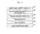
- the equalizeris iteratively computed so that a symbol from one transmit antenna is determined during each iteration. Initially the received samples are stored in a memory. After a symbol for an antenna is determined, the received samples for each of the remaining antennas are then recomputed by subtracting out the determined symbol from the samples as they existed prior to determining the symbol. Once all the symbols for all of the transmit antennas are determined for a symbol period are determined the operation begins anew with the samples corresponding to the next symbol period.
- FIG. 1shows an embodiment a multiple-input multiple-output (MIMO) wireless system in which the bit error rate floor caused by time dispersion is reduced by employing a joint minimum mean square error (MMSE) equalizer for all of the respective transmit antenna—receive antenna pairings that are possible in the MIMO system, in accordance with the principles of the invention;
- MIMOmultiple-input multiple-output
- FIG. 2shows an exemplary process, in flow chart form, for the overall operation of system of FIG. 1 ;
- FIG. 3shows in more detail the process by which the weights employed by the joint equalizer of FIG. 1 are determined
- FIG. 4shows another exemplary process, in flow chart form, for the overall operation of system of FIG. 1 ;
- FIG. 5shows another embodiment a multiple-input multiple-output (MIMO) wireless system in which the bit error rate floor caused by time dispersion is reduced by employing a joint minimum mean square error (MMSE) equalizer for all of the respective transmit antenna—receive antenna pairings that are possible in the MIMO system, in accordance with the principles of the invention;
- MIMOmultiple-input multiple-output
- FIG. 6shows a more detailed version of a buffer-subtractor of FIG. 5 ;
- FIG. 7shows an exemplary process, in flow chart form, for the overall operation of system of FIG. 5 ;
- FIG. 8shows a particular embodiment of the joint equalizer of FIG. 1 , in which the equalization is performed in the discrete frequency domain, in accordance with an aspect of the invention.
- FIG. 9shows a particular embodiment of the joint equalizer of FIG. 1 , in which the equalization is calculated in the discrete frequency domain and applied in the time domain.
- any block diagrams hereinrepresent conceptual views of illustrative circuitry embodying the principles of the invention.
- any flow charts, flow diagrams, state transition diagrams, pseudocode, and the likerepresent various processes which may be substantially represented in computer readable medium and so executed by a computer or processor, whether or not such computer or processor is explicitly shown.
- processorsmay be provided through the use of dedicated hardware as well as hardware capable of executing software in association with appropriate software.
- the functionsmay be provided by a single dedicated processor, by a single shared processor, or by a plurality of individual processors, some of which may be shared.
- processoror “controller” should not be construed to refer exclusively to hardware capable of executing software, and may implicitly include, without limitation, digital signal processor (DSP) hardware, network processor, application specific integrated circuit (ASIC), field programmable gate array (FPGA), read-only memory (ROM) for storing software, random access memory (RAM), and non-volatile storage. Other hardware, conventional and/or custom, may also be included.
- DSPdigital signal processor
- ASICapplication specific integrated circuit
- FPGAfield programmable gate array
- ROMread-only memory
- RAMrandom access memory
- non-volatile storageOther hardware, conventional and/or custom, may also be included.
- any switches shown in the FIGS.are conceptual only. Their function may be carried out through the operation of program logic, through dedicated logic, through the interaction of program control and dedicated logic, or even manually, the particular technique being selectable by the implementor as more specifically understood from the context.
- any element expressed as a means for performing a specified functionis intended to encompass any way of performing that function including, for example, a) a combination of circuit elements which performs that function or b) software in any form, including, therefore, firmware, microcode or the like, combined with appropriate circuitry for executing that software to perform the function.
- the invention as defined by such claimsresides in the fact that the functionalities provided by the various recited means are combined and brought together in the manner which the claims call for. Applicant thus regards any means which can provide those functionalities as equivalent as those shown herein.
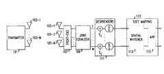
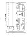
- FIG. 1shows an exemplary embodiment of a multiple-input multiple-output (MIMO) wireless system in which the bit error rate floor caused by time dispersion is reduced by employing a joint minimum mean square error (MMSE) equalizer for all of the respective transmit antenna—receive antenna pairings that are possible in the MIMO system, in accordance with the principles of the invention. Shown in FIG.
- MIMOmultiple-input multiple-output
- MMSEjoint minimum mean square error
- 1are a) transmitter 101 ; b) transmit antennas 103 ; including transmit antennas 103 - 1 through 103 -M; c) receive antennas 105 ; including receive antennas 105 - 1 through 105 -N; d) receiver front-end 107 ; e) joint equalizer 109 ; f) optional despreaders 111 ; g) soft bit mapper 112 , which may include optional spatial whitening filter 113 ; and optional a posteriori probability (APP) metric processor 115 .
- APPposteriori probability
- Transmitter 101is a MIMO transmitter, e.g., one in which an original data stream is divided into substreams and each resulting substream is transmitted as a modulated radio signal via an individual one of transmit antennas 103 .
- the transmitted signalspass to the receiver over a time dispersive channel such that signals from each transmit antenna 103 reach each of receive antennas 105 .
- Receive antennas 105convert the radio signals impinging upon them into electrical signals, which are supplied to receiver front-end 107 .
- Receiver front-end 107operates conventionally to produce a plurality of streams of binary numbers, each stream representing samples of the radio signals received at an associated one of antennas 105 .
- receiver front-end 107performs radio frequency downconversion, filtering, sampling, and analog-to-digital conversion. The resulting samples are provided to joint equalizer 109 .
- Joint equalizer 109compensates for the effects of the transmit signals from each of antennas 103 having passed through the channel as well as the interference that results from transmitting via multiple antennas simultaneously.
- the output of joint equalizer 109is M, i.e., the number of transmit antennas, streams of corrected symbols, or in the case of CDMA, streams of corrected chips which when properly combined form symbols. Operation of joint equalizer 109 will be described more fully hereinbelow. If CDMA is employed, the output of joint equalizer 109 is supplied to optional despreaders 111 , which produces symbols from the stream of chips supplied by joint equalizer 109 .
- the symbols producedmay then be further processed in the conventional manner for a MIMO system, e.g., soft bits may be developed by soft bit mapper 112 for use in a decoder, e.g., the well known “Turbo decoder”.
- the symbolsmay be supplied within soft bit mapper 112 to optional spatial whitening filter 113 , which makes the noise equal on each branch. Note that the whitening is performed only in the space domain. If whitening is performed in the time domain some temporal dispersion will be introduced into the signal.
- the symbols, or whitened symbols if optional spatial whitening filter 113 is employed,may further be supplied to optional a posteriori probability (APP) metric processor 115 within soft bit mapper 112 , in accordance with an aspect of the invention.
- APP metric processor 115performs a particular type of mapping from symbols to soft bits. Operation of APP metric processor 115 is described more fully hereinbelow.
- FIG. 2shows an exemplary process, in flow chart form, for the overall operation of system of FIG. 1 .
- initial values of parameters M, N, L, P, E, and dmust be determined. What each of these parameters represents is listed in Table 1.
- noise covariance R ppwhich contains samples of the autocorrelation of the chip pulse shape r(t), when CDMA is employed, or the symbol pulse shape autocorrelation, when CDMA is not employed.
- the process of FIG. 2is executed periodically, with a periodicity that preferably does not exceed the coherence time, T co , which is the time duration for which the channel properties are substantially constant.
- the processis entered in step 201 , in which L*P discrete channel estimations h o to h LP-1 are developed.
- the channel estimatemay be obtained using any conventional technique, e.g., by using correlators tuned to the pilot channel.
- Each of discrete channel estimationsis taken with a time spacing of the chip duration divided by P, for CDMA, or symbol duration divided by P for TDMA.
- the background noise plus interference power ⁇ n 2 and the power of the downlink from the base station to the terminal ⁇ x 2are determined in the conventional manner.
- the weights employed by joint equalizer 109are determined, as will be described fully further hereinbelow.
- step 205a set of P samples from each antenna is obtained.
- step 207the determined weights of joint equalizer 109 are applied to the samples from each antenna by joint equalizer 109 .
- the samplesare then despread by despreader 111 , if CDMA was employed, in optional step 209 .
- optional step 211conventional soft mapping of the symbols to soft bits is performed, and the resulting soft bits are supplied as an output for use by a decoder.
- conditional branch point 213tests to determine whether one coherence time has elapsed since the previous execution of step 201 .
- test result in step 213is NO, indicating that the channel is believed to still remain substantially the same as when it was last estimated, control passes to step 205 , and the process continues as described above. If the test result in step 213 is YES, indicating that sufficient time has passed such that the channel may have changed enough so as not to be considered substantially the same as when it was last estimated, control passes back to step 201 and the process continues as described above.
- FIG. 3shows in more detail the process of step 203 by which the weights employed by joint equalizer 109 . Note that the process requires the use of several matrices, and the dimensions of the various matrices are given in Table 2.
- step 301the channel estimates h o to h LP-1 for each transmit and receive pair obtained in step 201 are arranged in a respective matrix h n,m as shown in equation 1.
- step 303matrix convolution operator ⁇ (h n,m ) is then formed for each respective matrix h n,m , as shown in equation 2.
- step 305MIMO convolution operator ⁇ (H) is then formed from the various matrix convolution operators as shown in equation 3.
- delay vector e dis formed as shown in equation 4.
- Delay vector e dis a one dimensional vector with E+L ⁇ 1 elements which are all zero except for the single value at the E+L ⁇ 1 ⁇ d location, which has a value of 1.
- a typical value for d, which is selectable by the implementor,is such that the location which has a value of 1 is at the center of the vector.
- the purpose of delay vector e dis to impose the overall equalizer delay d onto the equalizer.
- delay matrix Ais computed from equation 5, in which I M is an identity matrix of size M ⁇ M.
- e d[0 . . . 100] equation (4)
- AI M ⁇ e d equation (5)
- equalizer weight matrix, Wis computed in accordance with equation 6, in which X H means the Hermitian transpose of X, which is the complex conjugate transpose of the vector or matrix X.
- step 205execution of step 205 is such that the P samples r of antenna n are initially arranged as a vector c shown in equation 7 , where k is the current received chip time index if CDMA is employed, or the symbol time index if CDMA is not employed. E consecutive in time vectors c for antenna n are then arranged as shown in equation 8, and the E consecutive in time vectors c for all of the N antennas are further arranged as shown in equation 9, forming a vector of received samples at time k.
- FIG. 4shows another exemplary process, in flow chart form, for the overall operation of system of FIG. 1 .
- the version of the process shown in FIG. 4is similar to that shown in FIG. 2 , but it is for embodiments of the invention that include optional spatial whitening filter 113 ( FIG. 1 ) and optional a posteriori probability (APP) metric processor 115 .
- all variables and parameters employed in the process of FIG. 4are the same as described for FIG. 2 .
- initial values of parameters M, N, L, P, E, and dmust be determined. Additionally, prior to performing the process of FIG. 4 it is necessary to determine R pp .
- the process of FIG. 4is executed periodically, with a periodicity that preferably does not exceed the coherence time, T co , which is the time duration for which the channel properties are substantially constant.
- the processis entered in step 401 , in which L*P discrete channel estimations h o to h LP-1 are developed.
- the background noise plus interference power ⁇ n 2 and the power of the downlink from the base station to the terminal ⁇ x 2are determined in the conventional manner.
- the weights W employed by joint equalizer 109are determined, as described hereinabove.
- the effective channel matrix H eff and, optionally, spatial whitening filter Qare determined, in accordance with an aspect of the invention.
- H effis determined as shown in equation 11, and Q is determined as shown in equation 12.
- Q( WW H ) ⁇ 1/2 equation (12)
- step 405a set of P samples from each antenna is obtained. Thereafter, in step 407 , the determined weights of joint equalizer 109 are applied to the samples from each antenna by joint equalizer 109 . The samples are then despread by despreader 111 , if CDMA was employed, in optional step 409 . In step 411 , whitening filter Q is applied to the despread, equalizer outputs of step 409 . In step 413 , APP softbits are computed, in accordance with an aspect of the invention, using equations 13 and 14. The softbits are the output of the process of FIG. 4 , and they may be made available to a decoder, e.g., a turbo decoder.
- a decodere.g., a turbo decoder.
- conditional branch point 415tests to determine whether one coherence time has elapsed since the previous execution of step 401 . If the test result in step 415 is NO, indicating that the channel is believed to still remain substantially the same as when it was last estimated, control passes to step 405 , and the process continues as described above. If the test result in step 415 is YES, indicating that sufficient time has passed such that the channel may have changed enough so as not to be considered substantially the same as when it was last estimated, control passes back to step 401 and the process continues as described above.
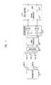
- FIG. 5shows another exemplary embodiment of a multiple-input multiple-output (MIMO) wireless system in which the bit error rate floor caused by time dispersion is reduced by employing a joint minimum mean square error (MMSE) equalizer for all of the respective transmit antenna—receive antenna pairings that are possible in the MIMO system, in accordance with the principles of the invention.
- MIMOmultiple-input multiple-output
- MMSEjoint minimum mean square error
- 5are a) transmitter 501 ; b) transmit antennas 503 ; including transmit antennas 503 - 1 through 503 -M; c) receive antennas 505 ; including receive antennas 505 - 1 through 505 -N; d) receiver front-end processor 507 ; e) buffer-subtractor 521 ; f) joint equalizer 523 ; g) optional despreader 525 ; h) soft bit mapper 527 ; i) space-time regenerator 529 ; j) order controller 531 and k) switch 533 .
- Transmitter 501is a MIMO transmitter, e.g., one in which an original data stream is divided into substreams and each resulting substream is transmitted as a modulated radio signal via an individual one of transmit antennas 503 .
- the transmitted signalspass to the receiver over a time dispersive channel such that signals from each transmit antenna 503 reach each of receive antennas 505 .
- Receive antennas 505convert the radio signals impinging upon them into electrical signals, which are supplied to receiver front-end processor 507 .
- Receiver front-end processor 507operates conventionally to produce a stream of binary numbers representing samples of the radio signals received at antennas 505 .
- receiver front-end processor 507performs radio frequency downconversion, filtering, sampling, and analog-to-digital conversion. The resulting samples are provided to buffer-substractor 521 .
- Buffer-subtractor 521is shown in more detail in FIG. 6 .
- Buffer subtractor 521includes buffer 601 , memory 603 , and subtractor 605 .
- Buffer 601stores a time consecutive set of samples from each of antennas 505 as those samples become available from front-end processor 507 .
- Buffer 601supplies the samples it receives from front-end processor 507 to memory 603 when an entire set is stored, i.e., the contents of buffer 601 are quickly dumped to memory 603 .
- Subtractor 605is cable of forming the difference between a specified location in memory 603 and a second input to buffer-subtractor 521 . The resulting difference is stored in the specified location in memory 603 .
- Joint equalizer 523performs M passes through memory 603 with a different equalizer weight w m in each pass. Each weight is chosen to emphasize transmit antenna m and to suppress transmit antennas m+1 through M.
- joint equalizer 523is supplied to conventional soft bit mapper 527 , via optional conventional despreader 525 if CDMA is employed.
- the soft bits developed by soft bit mapper 527are then supplied as an output, such as may be used by a decoder, e.g., the well known “Turbo decoder”.
- Space-time regenerator 529forms a set of time consecutive samples for each receive antenna assuming the soft symbol is correct. In other words, assuming a particular soft symbol had been the actual symbol transmitted by a particular transmit antenna, space-time regenerator 529 creates the corresponding effect that such a symbol would have caused on each of receive antennas 505 given the channel characteristics. Operation of space-time regenerator 529 will be explained more fully hereinbelow.
- Order controller 531determines, based on channel estimates, the signal from which transmit antenna will be processed at any particular time, as will be explained more fully hereinbelow.
- FIG. 7shows an exemplary process, in flow chart form, for the overall operation of system of FIG. 5 in which switch 533 is connected between despreader 525 and space-time regenerator 529 .
- initial values of parameters M, N, L, P, E, and dmust be determined. What each of these parameters represents is listed in Table 1. Additionally, prior to performing the process of FIG. 7 it is necessary to determine R pp , which is samples of the autocorrelation of the chip pulse shape r(t), when CDMA is employed, or the symbol pulse shape autocorrelation, when CDMA is not employed.
- the process of FIG. 7is executed periodically, with a periodicity that preferably does not exceed the coherence time, T co .
- the processis entered in step 701 , in which L*P discrete channel estimations h o to h LP-1 are developed.
- the channel estimatemay be obtained using any conventional technique, e.g., by using correlators tuned to the pilot channel.
- Each discrete channel estimationis taken with a time spacing of the chip duration divided by P, for CDMA, or symbol duration divided by P for TDMA.
- the background noise plus interference power ⁇ n 2 and the power of the downlink from the base station to the terminal ⁇ x 2are determined in the conventional manner.
- step 703order controller 531 determines, according to equations 15 and 16, the order in which the signals from the various transmit antennas will be processed, with the signal from a respective transmit antenna being processed for each execution of joint equalizer 523 .
- Sortis a function that rearranges the elements of vector P so that they run from largest to smallest and order is a list of all the antenna transmit antenna numbers as they should be processed by joint equalizer 523 . It is preferable to process the so-called “strong” signals first. However, the particular characteristic, or set of characteristics, which are used to define the “strength” of a signal is at the discretion of the implementer. In the particular embodiment shown herein, estimated signal powers are employed as the strength.
- step 705the equalizer weights for the particular antenna currently being processed, m, as specified by the order, is determined according to equations 17 and 18, in which delay vector a m is the m th row of delay matrix A which was described hereinabove.
- w ma m ⁇ ⁇ ⁇ ( H m ) H ⁇ ( ⁇ ⁇ ( H m ) H ⁇ ⁇ ⁇ ( H m ) + ⁇ n 2 ⁇ x 2 ⁇ R pp ) - 1 equation ⁇ ⁇ ( 17 )
- ⁇ ⁇ ( H m )[ 0 ⁇ ⁇ ( h 1 , 2 ) 0 ⁇ ⁇ ( h 1 , M ) 0 ⁇ ⁇ ( h 2 , 2 ) 0 ⁇ ⁇ ⁇ ( h 2 , 2 ) 0 ⁇ ⁇ ⁇ ⁇ ( h N , 2 ) 0 ⁇ ⁇ ( h N , M ) ] equation ⁇ ⁇ ( 18 )
- orderis vector which contains a listing of the M antenna numbers in the order in which they will be processed. Order may be the result of the well known function sort of MatLab®. Doing so accounts for the fact that signals from transmit antennas 1 through m ⁇ 1 have already been subtracted from the signal remaining to be processed for this set of samples.
- step 707a set of samples that span at least the duration of a data symbol is obtained from each receive antenna.
- counter variable mis initialized to 1.
- the samplesare then despread by despreader 525 , if CDMA was employed, in optional step 713 .
- step 715conventional soft mapping of the symbols to soft bits is performed, and the resulting soft bits are supplied as an output for use by a decoder.
- step 717samples are produced by space-time regenerator 529 according to equations 20 and 21.
- x ⁇ m ⁇ ( k )d ⁇ m ⁇ ( k ) ⁇ [ s ⁇ ( k ⁇ ⁇ G ) s ⁇ ( k ⁇ ⁇ G + 1 ) ⁇ s ⁇ ( k ⁇ ⁇ G + G - 1 ) ] equation ⁇ ⁇ ( 20 )
- y m ⁇ ( k )[ ⁇ ⁇ ( h 1 , m ) ⁇ ⁇ ( h 2 , m ) ⁇ ⁇ ⁇ ( h N , m ) ] ⁇ x ⁇ m ⁇ ( k ) equation ⁇ ⁇ ( 21 )
- step 719the output of space-time regenerator 529 is subtracted from the contents of memory 603 ( FIG. 6 ), as shown by equation 22.
- r ( k )r ( k ) ⁇ y m ( k ) equation (22)
- conditional branch point 721tests to determine if m is equal to M. If the test result in step 721 is NO, indicating that not all of the transmit antennas have yet had their signal contribution processed, m is incremented in step 723 . Thereafter, control passes back to step 711 and the process continues as described above. If the test result in step 712 is YES, indicating that all of the transmit antennas have had their signal contribution processed, control passes to conditional branch point 725 , which tests to determine whether one coherence time has elapsed since the previous execution of step 701 . If the test result in step 725 is NO, indicating that the channel is believed to still remain substantially the same as when it was last estimated, control passes to step 707 , and the process continues as described above. If the test result in step 725 is YES, indicating that sufficient time has passed such that the channel may have changed enough so as not to be considered substantially the same as when it was last estimated, control passes back to step 701 and the process continues as described above.
- switch 533is connected to the output of an error correction decoder which is either directly or indirectly connected to soft bit mapping 527 . Doing so may improve performance.
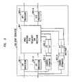
- FIG. 8shows a particular embodiment of joint equalizer 109 , in which the equalization is performed in the discrete frequency domain, in accordance with an aspect of the invention.
- Shown in FIG. 8 making up joint equalizer 109are a) fast Fourier transform (FFT) processors 801 , including EFT processors 801 - 1 through 801 -N, where N is the number of receive antennas; b) channel estimators 803 , including channel estimators 803 - 1 through 803 -N; c) fast Fourier transform (FFT) processors 805 , including FFT processors 805 - 1 through 805 -N*M, where M is the number of transmit antennas; d) MMSE detection per frequency bin processor 807 ; and e) inverse fast Fourier transform (IFFT) processors 809 , including IFFT processors 809 - 1 through 809 -M.
- FFTfast Fourier transform
- Each of FFT processors 801receives from front-end 107 a signal of time domain digital samples corresponding to a respective one of receive antennas 105 -N and performs the FFT algorithm on a set of consecutive samples to convert the time domain samples to samples in the discrete frequency domain, r n ( ⁇ ), where ⁇ is a particular discrete frequency.
- the number of samples Fis at the discretion of the implementer based on a tradeoff between the performance and complexity of FFT processors 801 . Typically the number of samples is a power of 2, e.g., 128, although the more samples the more accurate the equalization process will be.
- the possible values for ⁇are determined as
- ⁇2 ⁇ ⁇ ⁇ ⁇ n T s ⁇ F , where n ranges from 0 to F ⁇ 1.
- the resulting discrete frequency samples for each receive antennaare supplied to MMSE detection per frequency bin processor 807 .
- Each of channel estimators 803also receives from front-end 107 a signal of time domain digital samples corresponding to a respective one of receive antennas 105 -N and performs a channel estimate for the channel between its respective receive antenna and each of the M transmit antennas, thereby producing M channel estimates.
- Each channel estimateis a series of complex numbers that defines the impulse response of the channel.
- FFTFast Fourier transform
- processors 805each converts a respective channel estimate into the discrete frequency domain representation thereof, and supplies the resulting discrete frequency domain representation of the channel estimates h n,m ( ⁇ ) to MMSE detection per frequency bin processor 807 .
- ⁇ n 2is the background noise plus interference power
- ⁇ x 2is the power of the downlink signal from the base station to the terminal
- Iis the identity matrix
- Each of the resulting M components of resulting vector z( ⁇ )are then inverse frequency transformed from the discrete frequency domain into the time domain by inverse fast Fourier transform (IFFT) processors 809 .
- IFFTinverse fast Fourier transform
- the time domain equalized outputsare then supplied as the output of joint equalizer 109 .
- FIG. 9shows a particular embodiment of joint equalizer 109 in which the equalization is calculated in the discrete frequency domain and applied in the time domain, in accordance with an aspect of the invention.
- Shown in FIG. 9 making up joint equalizer 109are a) matrix finite impulse response (FIR) filter 901 ; b) channel estimators 903 , including channel estimators 903 - 1 through 903 -N; c) fast Fourier transform (FFT) processors 905 , including FFT processors 905 - 1 through 905 -N*M, where M is the number of transmit antennas; d) MMSE tap weight calculator 907 ; and e) inverse fast Fourier transform (IFFT) processors 909 , including IFFT processors 909 - 1 through 909 -N*M
- FFTfast Fourier transform
- Matrix finite impulse response (FIR) filter 901continuously receives from front-end 107 a signal of time domain digital samples corresponding to a respective one of receive antennas 105 -N.
- the number of taps of matrix FIR filter 901is at the discretion of the implementer based on a tradeoff between performance and complexity. Typically the number of samples is a power of 2, e.g., 128.
- Each of channel estimators 903also receives from front-end 107 a signal of time domain digital samples corresponding to a respective one of receive antennas 105 -N and performs a channel estimate for the channel between its respective receive antenna and each of the M transmit antennas, thereby producing M channel estimates.
- Each channel estimateis a series of complex numbers that defines the impulse response of the channel.
- FFTFast Fourier transform
- processors 905each converts a respective channel estimate into the discrete frequency domain, and supplies the resulting discrete frequency domain representation of the channel estimates h n,m ( ⁇ ) to MMSE tap weight calculator 907 .
- the number of samples employed by FFT processors 905 for each conversionshould be the same as the number of taps in matrix FIR filter 901 .
- Each of the resulting M components of resulting vector S( ⁇ )are grouped by frequency into frequency vectors, and are then the frequency vectors are inverse frequency transformed from the discrete frequency domain to become filter weights in the time domain by inverse fast Fourier transform (IFFT) processors 909 .
- IFFTinverse fast Fourier transform
- the weightsare then supplied to matrix FIR filter 901 which utilizes them to perform equalization in the time domain on the signals received from front-end 107 as shown by equation 28,
- y (k)is the vector output at time k, y having M components—one for each transmit antenna—
- S jis the M ⁇ N filter matrix for delay j, which is the inverse Fourier transform of S( ⁇ )
- r(k)is the vector input signal which is received by matrix FIR filter 901 as defined in equation (9)
- Fis the number of samples taken for each FFT.
- equalizer algorithmswhich approximate the operation and performance of MMSE, such as least mean square (LMS), recursive least squares (RLS), or minimum intersymbol interference (ISI) subject to an anchor condition, can be employed in a joint manner, e.g., in a space manner, in the implementation of joint equalizer 109 .
- LMSleast mean square
- RLSrecursive least squares
- ISIminimum intersymbol interference
- the techniques of the instant inventionmay be employed in systems in which the various transmit antennas are transmitting at different data rates, e.g., using different encoding rates and/or transmit constellations, such as quaternary phase-shift keying (QPSK) or 16-ary quadrature amplitude modulation (16-QAM).
- QPSKquaternary phase-shift keying
- 16-QAM16-ary quadrature amplitude modulation
Landscapes
- Engineering & Computer Science (AREA)
- Computer Networks & Wireless Communication (AREA)
- Signal Processing (AREA)
- Power Engineering (AREA)
- Radio Transmission System (AREA)
- Cable Transmission Systems, Equalization Of Radio And Reduction Of Echo (AREA)
Abstract
Description
| TABLE 1 |
| Parameter Definitions |
| M | number of transmit antennas | ||
| N | number of receive antennas | ||
| L | length of the channel impulse response (chips) | ||
| P | over-sampling factor | ||
| E | length of the equalizer (chips) | ||
| d | equalizer delay (chips) | ||
| σn2 | power of interference + noise (RF bandwidth) | ||
| σx2 | power of downlink signal (RF bandwidth) | ||
| G | Number of CDMA chips per symbol | ||
| TABLE 2 | |||
| Matrix | Dimension | ||
| Rp | EP × EP | ||
| Rpp | NEP × NEP | ||
| Γ(hn,m) | EP × (E + L − 1) | ||
| Γ(H) | NEP × M(E + L − 1) | ||
| Γ(Hm) | NEP × M(E + L − 1) | ||
| ed | (E + L − 1) × 1 | ||
| A | M × M(E + L − 1) | ||
| am | 1 × M(E + L − 1) | ||
| W | M × | ||
| w | |||
| m | 1 × NEP | ||
| Q | M × M | ||
ed=[0 . . . 100] equation (4)
A=IM⊕ed equation (5)
y(k)=Wr(k) equation (10)
Heff(m,n)=enTWΓ(H)emm=1:M, n=1:N equation (11)
Q=(WWH)−1/2 equation (12)
P=∥diag(WΓ(H))∥2 equation (15)
[P′,order]=sort(P) equation (16)
y(k)=WmTr(k) equation (19)
r(k)=r(k)−ym(k) equation (22)
where n ranges from 0 to F−1. The resulting discrete frequency samples for each receive antenna are supplied to MMSE detection per
z(ω)=(H(ω)HH(ω)+σ2I)−1H(ω)Hr(ω) equation (23)
S(ω)=(H(ω)HH(ω)+σ2I)−1H(ω)H equation (27)
where H(ω), σ2are defined as explained hereinabove in connection with
Claims (38)
z(ω)=(H(ω)HH(ω)+σ2I)−1H(ω)Hr(ω)
S(ω)=(H(ω)HH(ω)+σ2I)−1H(ω)H
y(k)=Wr(k)
Priority Applications (3)
| Application Number | Priority Date | Filing Date | Title |
|---|---|---|---|
| US09/938,453US7359466B2 (en) | 2001-08-24 | 2001-08-24 | Signal detection by a receiver in a multiple antenna time-dispersive system |
| EP02252090AEP1289182A3 (en) | 2001-08-24 | 2002-03-22 | Signal detection by a receiver in a multiple antenna time-dispersive system |
| JP2002242781AJP2003110474A (en) | 2001-08-24 | 2002-08-23 | Signal detection by receiver in a plurality of antenna time dispersion system |
Applications Claiming Priority (1)
| Application Number | Priority Date | Filing Date | Title |
|---|---|---|---|
| US09/938,453US7359466B2 (en) | 2001-08-24 | 2001-08-24 | Signal detection by a receiver in a multiple antenna time-dispersive system |
Publications (2)
| Publication Number | Publication Date |
|---|---|
| US20030076908A1 US20030076908A1 (en) | 2003-04-24 |
| US7359466B2true US7359466B2 (en) | 2008-04-15 |
Family
ID=25471471
Family Applications (1)
| Application Number | Title | Priority Date | Filing Date |
|---|---|---|---|
| US09/938,453Expired - LifetimeUS7359466B2 (en) | 2001-08-24 | 2001-08-24 | Signal detection by a receiver in a multiple antenna time-dispersive system |
Country Status (3)
| Country | Link |
|---|---|
| US (1) | US7359466B2 (en) |
| EP (1) | EP1289182A3 (en) |
| JP (1) | JP2003110474A (en) |
Cited By (32)
| Publication number | Priority date | Publication date | Assignee | Title |
|---|---|---|---|---|
| US20050175115A1 (en)* | 2003-12-17 | 2005-08-11 | Qualcomm Incorporated | Spatial spreading in a multi-antenna communication system |
| US20050180312A1 (en)* | 2004-02-18 | 2005-08-18 | Walton J. R. | Transmit diversity and spatial spreading for an OFDM-based multi-antenna communication system |
| US20050195733A1 (en)* | 2004-02-18 | 2005-09-08 | Walton J. R. | Transmit diversity and spatial spreading for an OFDM-based multi-antenna communication system |
| US20050238111A1 (en)* | 2004-04-09 | 2005-10-27 | Wallace Mark S | Spatial processing with steering matrices for pseudo-random transmit steering in a multi-antenna communication system |
| US20050249174A1 (en)* | 2004-05-07 | 2005-11-10 | Qualcomm Incorporated | Steering diversity for an OFDM-based multi-antenna communication system |
| US20050265275A1 (en)* | 2004-05-07 | 2005-12-01 | Howard Steven J | Continuous beamforming for a MIMO-OFDM system |
| US20060159160A1 (en)* | 2005-01-14 | 2006-07-20 | Qualcomm Incorporated | Optimal weights for MMSE space-time equalizer of multicode CDMA system |
| US20060199557A1 (en)* | 2005-03-04 | 2006-09-07 | Nec Corporation | MIMO receiver, MIMO reception method and wireless communication system |
| US20060222078A1 (en)* | 2005-03-10 | 2006-10-05 | Raveendran Vijayalakshmi R | Content classification for multimedia processing |
| US20060245477A1 (en)* | 2005-04-27 | 2006-11-02 | Nec Corporation | CDMA reception method, device, and wireless communication system |
| US20060251421A1 (en)* | 2005-05-09 | 2006-11-09 | Ben Gurion University Of The Negev, Research And Development Authority | Improved free space optical bus |
| US20070058735A1 (en)* | 2005-09-13 | 2007-03-15 | Sbc Knowledge Ventures Lp | Method and apparatus for equalizing signals |
| US20070074266A1 (en)* | 2005-09-27 | 2007-03-29 | Raveendran Vijayalakshmi R | Methods and device for data alignment with time domain boundary |
| US20070171972A1 (en)* | 2005-10-17 | 2007-07-26 | Qualcomm Incorporated | Adaptive gop structure in video streaming |
| US20070171280A1 (en)* | 2005-10-24 | 2007-07-26 | Qualcomm Incorporated | Inverse telecine algorithm based on state machine |
| US20070268181A1 (en)* | 2006-05-22 | 2007-11-22 | Qualcomm Incorporated | Derivation and feedback of transmit steering matrix |
| US20080151101A1 (en)* | 2006-04-04 | 2008-06-26 | Qualcomm Incorporated | Preprocessor method and apparatus |
| US7437135B2 (en)* | 2003-10-30 | 2008-10-14 | Interdigital Technology Corporation | Joint channel equalizer interference canceller advanced receiver |
| US20090003414A1 (en)* | 2003-10-30 | 2009-01-01 | Daniel Yellin | Unified mmse equalization and multi-user detection approach for use in a cdma system |
| US20090054093A1 (en)* | 2007-08-15 | 2009-02-26 | Qualcomm Incorporated | Antenna switching and uplink sounding channel measurement |
| US20090262872A1 (en)* | 2008-04-16 | 2009-10-22 | Nec Laboratories America, Inc. | Receiver with prefiltering for discrete fourier transform-spread-orthogonal frequency division multiplexing (dft-s-ofdm) based systems |
| US20100214065A1 (en)* | 2006-09-01 | 2010-08-26 | Intermec Ip Corp. | Rfid tags with cdma communication capabilities |
| US20100271179A1 (en)* | 2006-09-01 | 2010-10-28 | Maltseff Paul A | Rfid tags with orthogonal communication capabilities, and associated systems |
| US20100277318A1 (en)* | 2006-09-01 | 2010-11-04 | Intermec Ip Corp. | Rfid tag system with block coding, such as space-time block coding |
| US20100323653A1 (en)* | 2009-06-23 | 2010-12-23 | Lockheed Martin Corporation | Device and method for matrixed adaptive equalizing for communication receivers configured to an antenna array |
| US20110142097A1 (en)* | 2004-01-13 | 2011-06-16 | Qualcomm Incorporated | Data transmission with spatial spreading in a mimo communication system |
| US7978778B2 (en) | 2004-09-03 | 2011-07-12 | Qualcomm, Incorporated | Receiver structures for spatial spreading with space-time or space-frequency transmit diversity |
| US7978649B2 (en) | 2004-07-15 | 2011-07-12 | Qualcomm, Incorporated | Unified MIMO transmission and reception |
| US7991065B2 (en) | 2004-06-30 | 2011-08-02 | Qualcomm, Incorporated | Efficient computation of spatial filter matrices for steering transmit diversity in a MIMO communication system |
| US8543070B2 (en) | 2006-04-24 | 2013-09-24 | Qualcomm Incorporated | Reduced complexity beam-steered MIMO OFDM system |
| US8654848B2 (en) | 2005-10-17 | 2014-02-18 | Qualcomm Incorporated | Method and apparatus for shot detection in video streaming |
| US20190372821A1 (en)* | 2015-11-13 | 2019-12-05 | Huawei Technologies Co., Ltd. | Data transmission method and apparatus |
Families Citing this family (55)
| Publication number | Priority date | Publication date | Assignee | Title |
|---|---|---|---|---|
| US7769078B2 (en)* | 2000-12-22 | 2010-08-03 | Telefonaktiebolaget Lm Ericsson (Publ) | Apparatus, methods and computer program products for delay selection in a spread-spectrum receiver |
| US9236902B2 (en)* | 2001-08-28 | 2016-01-12 | Texas Instruments Incorporated | Combined equalizer and spread spectrum interference canceller method and implementation for the downlink of CDMA systems |
| JP3814182B2 (en)* | 2001-10-17 | 2006-08-23 | 国立大学法人 北海道大学 | Wireless device and adaptive array processing method |
| US20030161258A1 (en)* | 2002-02-22 | 2003-08-28 | Jianzhong Zhang | Apparatus, and associated method, for a multiple-input, multiple-output communications system |
| AU2003228602A1 (en)* | 2002-04-22 | 2003-11-03 | Cognio, Inc. | Multiple-input multiple-output radio transceiver |
| US6757321B2 (en) | 2002-05-22 | 2004-06-29 | Interdigital Technology Corporation | Segment-wise channel equalization based data estimation |
| US7212566B2 (en)* | 2002-06-26 | 2007-05-01 | Nokia Corporation | Apparatus, and associated method, for performing joint equalization in a multiple-input, multiple-output communication system |
| US7167507B2 (en)* | 2002-07-01 | 2007-01-23 | Lucent Technologies Inc. | Equalizer and method for performing equalization in a wireless communications system |
| US7042967B2 (en)* | 2003-03-03 | 2006-05-09 | Interdigital Technology Corporation | Reduced complexity sliding window based equalizer |
| US7428279B2 (en)* | 2003-03-03 | 2008-09-23 | Interdigital Technology Corporation | Reduced complexity sliding window based equalizer |
| US7346103B2 (en) | 2003-03-03 | 2008-03-18 | Interdigital Technology Corporation | Multi user detection using equalization and successive interference cancellation |
| GB2400000A (en)* | 2003-03-24 | 2004-09-29 | Univ Bristol | Iterative frequency domain equalizer for a MIMO system receiver |
| JP2005057497A (en)* | 2003-08-04 | 2005-03-03 | Science Univ Of Tokyo | Wireless transmission control method, wireless receiver, and wireless transmitter |
| EP1661333B1 (en)* | 2003-08-26 | 2012-08-08 | Nxp B.V. | Wireless device with dynamic fragmentation threshold adjustment |
| US7616698B2 (en) | 2003-11-04 | 2009-11-10 | Atheros Communications, Inc. | Multiple-input multiple output system and method |
| FI20031609A0 (en)* | 2003-11-06 | 2003-11-06 | Nokia Corp | Communication method, receiver and base station |
| US7321646B2 (en) | 2003-11-18 | 2008-01-22 | Telefonaktiebolaget Lm Ericsson (Publ) | Methods and apparatus for pre-filtering a signal to increase signal-to-noise ratio and decorrelate noise |
| KR100703263B1 (en) | 2003-12-02 | 2007-04-03 | 삼성전자주식회사 | Apparatus and method for removing interference signal in mobile communication system using multiple antennas |
| KR100580843B1 (en)* | 2003-12-22 | 2006-05-16 | 한국전자통신연구원 | V―Channel transfer function matrix processing apparatus and processing method thereof in BSL |
| KR100605861B1 (en)* | 2004-02-02 | 2006-08-01 | 삼성전자주식회사 | Signal Receiving Device and Method of Communication System Using Multiple Input Multiple Output Method |
| US7324583B2 (en)* | 2004-02-13 | 2008-01-29 | Nokia Corporation | Chip-level or symbol-level equalizer structure for multiple transmit and receiver antenna configurations |
| WO2005086500A1 (en)* | 2004-02-27 | 2005-09-15 | Nokia Corporation | Constrained optimization based mimo lmmse-sic receiver for cdma downlink |
| JP4574210B2 (en) | 2004-04-16 | 2010-11-04 | 株式会社エヌ・ティ・ティ・ドコモ | Receiver, transmitter, radio communication system, and channel estimation method |
| US7660340B2 (en)* | 2004-06-22 | 2010-02-09 | Alcatel-Lucent Usa Inc. | Method of receiver processing of CDMA signals in a CDMA system |
| BRPI0513071A (en)* | 2004-08-05 | 2008-04-22 | Matsushita Electric Industrial Co Ltd | radio transmission device, radio reception device, radio transmission method and radio reception method |
| US7711035B2 (en)* | 2004-09-17 | 2010-05-04 | Telefonaktiebolaget Lm Ericsson (Publ) | Method and apparatus for suppressing communication signal interference |
| US7433434B2 (en)* | 2004-10-01 | 2008-10-07 | General Dynamics C4 Systems, Inc. | Communication channel tracking apparatus |
| US7539262B2 (en)* | 2004-12-14 | 2009-05-26 | Interdigital Technology Corporation | Method and apparatus for performing chip level equalization using joint processing |
| CN101958853B (en)* | 2005-01-17 | 2012-11-21 | 夏普株式会社 | Radio communication device |
| US7570689B2 (en)* | 2005-02-14 | 2009-08-04 | Interdigital Technology Corporation | Advanced receiver with sliding window block linear equalizer |
| CA2516000A1 (en)* | 2005-08-15 | 2007-02-15 | Research In Motion Limited | Joint space-time optimum filters (jstof) with at least one virtual antenna, at least one channel, and joint filter weight and cir estimation |
| JP4666150B2 (en)* | 2005-05-31 | 2011-04-06 | 日本電気株式会社 | MIMO receiving apparatus, receiving method, and radio communication system |
| US7548589B2 (en)* | 2005-06-13 | 2009-06-16 | Qualcomm Incorporated | Method and apparatus for generating weights for transmit diversity in wireless communication |
| US20070042741A1 (en)* | 2005-08-15 | 2007-02-22 | Research In Motion Limited | Wireless Communications Device Including a Joint Space-Time Optimum Filters (JSTOF) Using QR and Eigenvalue Decompositions |
| US20070133814A1 (en)* | 2005-08-15 | 2007-06-14 | Research In Motion Limited | Joint Space-Time Optimum Filter (JSTOF) Using Cholesky and Eigenvalue Decompositions |
| US20070053416A1 (en)* | 2005-09-08 | 2007-03-08 | Yuan Li | Methods and apparatus to perform closed-loop transmit diversity with frequency-domain equalizers |
| US20070053417A1 (en)* | 2005-09-08 | 2007-03-08 | Toshio Nagata | Methods and apparatus to perform fractional-spaced channel estimation for frequency-domain equalizers |
| US7852951B2 (en)* | 2005-09-30 | 2010-12-14 | Intel Corporation | Multicarrier receiver for multiple-input multiple-output wireless communication systems and method |
| EP1938465A4 (en)* | 2005-11-21 | 2012-08-08 | Qualcomm Inc | Optimal weights for mmse space-time equalizer of multicode cdma system |
| KR20070061215A (en)* | 2005-12-08 | 2007-06-13 | 한국전자통신연구원 | Transmission and reception device of wideband wireless channel measurement device using multiple carriers |
| US20070230638A1 (en)* | 2006-03-30 | 2007-10-04 | Meir Griniasty | Method and apparatus to efficiently configure multi-antenna equalizers |
| CN100444543C (en)* | 2006-03-31 | 2008-12-17 | 东南大学 | Spatial filtering detection method for multi-antenna wireless communication system |
| CN100499611C (en)* | 2006-03-31 | 2009-06-10 | 东南大学 | Inspection of blank field maximum rear-proving probability in wireless communication system |
| US7889822B2 (en)* | 2006-09-21 | 2011-02-15 | Broadcom Corporation | Frequency domain equalizer with one dominant interference cancellation for dual antenna radio |
| HUE047810T2 (en)* | 2006-11-06 | 2020-05-28 | Qualcomm Inc | MIMO detection by extinguishing the interference of the on-time signal component |
| KR100949987B1 (en)* | 2007-01-04 | 2010-03-26 | 삼성전자주식회사 | Receiver and method in wireless communication system |
| KR101059969B1 (en)* | 2007-02-23 | 2011-08-26 | 니폰덴신뎅와 가부시키가이샤 | Receiver, transmitter, radio transceiver system and radio reception method |
| US7933372B2 (en)* | 2007-03-08 | 2011-04-26 | Freescale Semiconductor, Inc. | Successive interference cancellation based on the number of retransmissions |
| GB2463872B (en)* | 2008-09-24 | 2012-04-18 | Toshiba Res Europ Ltd | A MMSE equaliser |
| US8724685B2 (en)* | 2010-10-21 | 2014-05-13 | Samsung Electronics Co., Ltd. | Apparatus and method for interference cancellation in MIMO wireless communication system |
| US20120147942A1 (en)* | 2010-12-10 | 2012-06-14 | Futurewei Technologies, Inc. | System and Method for Signaling and Detecting in Wireless Communications Systems |
| US8787427B2 (en)* | 2012-05-10 | 2014-07-22 | Telefonaktiebolaget L M Ericsson (Publ) | Chip-level processing for joint demodulation in CDMA receivers |
| US9787356B2 (en)* | 2015-09-22 | 2017-10-10 | Nxp Usa, Inc. | System and method for large dimension equalization using small dimension equalizers |
| US9667455B1 (en) | 2016-03-23 | 2017-05-30 | Nxp Usa, Inc. | System and method for large dimension equalization using small dimension equalizers and bypassed equalizers |
| CN109117698B (en)* | 2017-12-27 | 2022-04-19 | 南京世海声学科技有限公司 | Noise background estimation method based on minimum mean square error criterion |
Citations (11)
| Publication number | Priority date | Publication date | Assignee | Title |
|---|---|---|---|---|
| US5550810A (en)* | 1993-08-24 | 1996-08-27 | U.S. Philips Corporation | Direct sequence code division multiple access (DS-CDMA) communication system and a receiver for use in such a system |
| US6145114A (en)* | 1997-08-14 | 2000-11-07 | Her Majesty The Queen In Right Of Canada, As Represented By The Minister Of Industry Through Communications Research Centre | Method of enhanced max-log-a posteriori probability processing |
| WO2001033761A1 (en) | 1999-11-02 | 2001-05-10 | Iospan Wireless, Inc. | Method and wireless communications systems using coordinated transmission and training for interference mitigation |
| US6314147B1 (en)* | 1997-11-04 | 2001-11-06 | The Board Of Trustees Of The Leland Stanford Junior University | Two-stage CCI/ISI reduction with space-time processing in TDMA cellular networks |
| US20020126741A1 (en)* | 2000-12-29 | 2002-09-12 | Motorola Inc. | Method and system for transmission and frequency domain equalization for wideband CDMA system |
| US20030003880A1 (en)* | 2001-03-23 | 2003-01-02 | Fuyun Ling | Method and apparatus for utilizing channel state information in a wireless communication system |
| US20030035491A1 (en) | 2001-05-11 | 2003-02-20 | Walton Jay R. | Method and apparatus for processing data in a multiple-input multiple-output (MIMO) communication system utilizing channel state information |
| US6574211B2 (en)* | 1997-11-03 | 2003-06-03 | Qualcomm Incorporated | Method and apparatus for high rate packet data transmission |
| US6731700B1 (en)* | 2001-01-04 | 2004-05-04 | Comsys Communication & Signal Processing Ltd. | Soft decision output generator |
| US6795508B1 (en)* | 1997-12-02 | 2004-09-21 | Qualcomm, Incorporated | Method and apparatus for obtaining transmit diversity using switched antennas |
| US7027523B2 (en)* | 2001-06-22 | 2006-04-11 | Qualcomm Incorporated | Method and apparatus for transmitting data in a time division duplexed (TDD) communication system |
- 2001
- 2001-08-24USUS09/938,453patent/US7359466B2/ennot_activeExpired - Lifetime
- 2002
- 2002-03-22EPEP02252090Apatent/EP1289182A3/ennot_activeCeased
- 2002-08-23JPJP2002242781Apatent/JP2003110474A/enactivePending
Patent Citations (12)
| Publication number | Priority date | Publication date | Assignee | Title |
|---|---|---|---|---|
| US5550810A (en)* | 1993-08-24 | 1996-08-27 | U.S. Philips Corporation | Direct sequence code division multiple access (DS-CDMA) communication system and a receiver for use in such a system |
| US6145114A (en)* | 1997-08-14 | 2000-11-07 | Her Majesty The Queen In Right Of Canada, As Represented By The Minister Of Industry Through Communications Research Centre | Method of enhanced max-log-a posteriori probability processing |
| US6574211B2 (en)* | 1997-11-03 | 2003-06-03 | Qualcomm Incorporated | Method and apparatus for high rate packet data transmission |
| US6314147B1 (en)* | 1997-11-04 | 2001-11-06 | The Board Of Trustees Of The Leland Stanford Junior University | Two-stage CCI/ISI reduction with space-time processing in TDMA cellular networks |
| US6795508B1 (en)* | 1997-12-02 | 2004-09-21 | Qualcomm, Incorporated | Method and apparatus for obtaining transmit diversity using switched antennas |
| WO2001033761A1 (en) | 1999-11-02 | 2001-05-10 | Iospan Wireless, Inc. | Method and wireless communications systems using coordinated transmission and training for interference mitigation |
| US20020126741A1 (en)* | 2000-12-29 | 2002-09-12 | Motorola Inc. | Method and system for transmission and frequency domain equalization for wideband CDMA system |
| US6731700B1 (en)* | 2001-01-04 | 2004-05-04 | Comsys Communication & Signal Processing Ltd. | Soft decision output generator |
| US20030003880A1 (en)* | 2001-03-23 | 2003-01-02 | Fuyun Ling | Method and apparatus for utilizing channel state information in a wireless communication system |
| US20030035491A1 (en) | 2001-05-11 | 2003-02-20 | Walton Jay R. | Method and apparatus for processing data in a multiple-input multiple-output (MIMO) communication system utilizing channel state information |
| US6785341B2 (en)* | 2001-05-11 | 2004-08-31 | Qualcomm Incorporated | Method and apparatus for processing data in a multiple-input multiple-output (MIMO) communication system utilizing channel state information |
| US7027523B2 (en)* | 2001-06-22 | 2006-04-11 | Qualcomm Incorporated | Method and apparatus for transmitting data in a time division duplexed (TDD) communication system |
Non-Patent Citations (2)
| Title |
|---|
| Irfan Ghauri et al., "Linear Receivers for the DS-CDMA Downlink Exploiting Orthogonality of Spreading Sequences", 32<SUP>nd </SUP>Asilomar Conference, Nov. 1-4, 1998, pp. 650-654. |
| J-K Hwang et al., "Performance Analysis Of MIMO-MMSE-DFE Multiuser Receiver For TDMA Mobile Systems With Spatial Diversity", VTC 2001 Spring IEEE VTS 54RD Vehicular Technology Conferences, Rhodes, Greece, May 6-9, 2001, CONF. 53, vol. 1 of 4, pp. 142-1456. |
Cited By (79)
| Publication number | Priority date | Publication date | Assignee | Title |
|---|---|---|---|---|
| US7437135B2 (en)* | 2003-10-30 | 2008-10-14 | Interdigital Technology Corporation | Joint channel equalizer interference canceller advanced receiver |
| US20090003414A1 (en)* | 2003-10-30 | 2009-01-01 | Daniel Yellin | Unified mmse equalization and multi-user detection approach for use in a cdma system |
| US8144748B2 (en)* | 2003-10-30 | 2012-03-27 | Marvell World Trade Ltd. | Method and apparatus for equalizing CDMA signals |
| US8548028B2 (en) | 2003-10-30 | 2013-10-01 | Marvell World Trade Ltd. | Method and apparatus for equalizing CDMA signals |
| US11171693B2 (en) | 2003-12-17 | 2021-11-09 | Qualcomm Incorporated | Spatial spreading in a multi-antenna communication system |
| US8204149B2 (en) | 2003-12-17 | 2012-06-19 | Qualcomm Incorporated | Spatial spreading in a multi-antenna communication system |
| US9787375B2 (en) | 2003-12-17 | 2017-10-10 | Qualcomm Incorporated | Spatial spreading in a multi-antenna communication system |
| US8903016B2 (en) | 2003-12-17 | 2014-12-02 | Qualcomm Incorporated | Spatial spreading in a multi-antenna communication system |
| US20050175115A1 (en)* | 2003-12-17 | 2005-08-11 | Qualcomm Incorporated | Spatial spreading in a multi-antenna communication system |
| US10476560B2 (en) | 2003-12-17 | 2019-11-12 | Qualcomm Incorporated | Spatial spreading in a multi-antenna communication system |
| US20110142097A1 (en)* | 2004-01-13 | 2011-06-16 | Qualcomm Incorporated | Data transmission with spatial spreading in a mimo communication system |
| US8325844B2 (en) | 2004-01-13 | 2012-12-04 | Qualcomm Incorporated | Data transmission with spatial spreading in a MIMO communication system |
| US8169889B2 (en) | 2004-02-18 | 2012-05-01 | Qualcomm Incorporated | Transmit diversity and spatial spreading for an OFDM-based multi-antenna communication system |
| US20050195733A1 (en)* | 2004-02-18 | 2005-09-08 | Walton J. R. | Transmit diversity and spatial spreading for an OFDM-based multi-antenna communication system |
| US8520498B2 (en) | 2004-02-18 | 2013-08-27 | Qualcomm Incorporated | Transmit diversity and spatial spreading for an OFDM-based multi-antenna communication system |
| US20100002570A9 (en)* | 2004-02-18 | 2010-01-07 | Walton J R | Transmit diversity and spatial spreading for an OFDM-based multi-antenna communication system |
| US20050180312A1 (en)* | 2004-02-18 | 2005-08-18 | Walton J. R. | Transmit diversity and spatial spreading for an OFDM-based multi-antenna communication system |
| US20050238111A1 (en)* | 2004-04-09 | 2005-10-27 | Wallace Mark S | Spatial processing with steering matrices for pseudo-random transmit steering in a multi-antenna communication system |
| US20080273617A1 (en)* | 2004-05-07 | 2008-11-06 | Qualcomm Incorporated | Steering diversity for an ofdm-based multi-antenna communication system |
| US8923785B2 (en) | 2004-05-07 | 2014-12-30 | Qualcomm Incorporated | Continuous beamforming for a MIMO-OFDM system |
| US20050249174A1 (en)* | 2004-05-07 | 2005-11-10 | Qualcomm Incorporated | Steering diversity for an OFDM-based multi-antenna communication system |
| US8909174B2 (en) | 2004-05-07 | 2014-12-09 | Qualcomm Incorporated | Continuous beamforming for a MIMO-OFDM system |
| US20050265275A1 (en)* | 2004-05-07 | 2005-12-01 | Howard Steven J | Continuous beamforming for a MIMO-OFDM system |
| US8285226B2 (en) | 2004-05-07 | 2012-10-09 | Qualcomm Incorporated | Steering diversity for an OFDM-based multi-antenna communication system |
| US7991065B2 (en) | 2004-06-30 | 2011-08-02 | Qualcomm, Incorporated | Efficient computation of spatial filter matrices for steering transmit diversity in a MIMO communication system |
| US8767701B2 (en) | 2004-07-15 | 2014-07-01 | Qualcomm Incorporated | Unified MIMO transmission and reception |
| US7978649B2 (en) | 2004-07-15 | 2011-07-12 | Qualcomm, Incorporated | Unified MIMO transmission and reception |
| US7978778B2 (en) | 2004-09-03 | 2011-07-12 | Qualcomm, Incorporated | Receiver structures for spatial spreading with space-time or space-frequency transmit diversity |
| US20060159160A1 (en)* | 2005-01-14 | 2006-07-20 | Qualcomm Incorporated | Optimal weights for MMSE space-time equalizer of multicode CDMA system |
| US8780957B2 (en)* | 2005-01-14 | 2014-07-15 | Qualcomm Incorporated | Optimal weights for MMSE space-time equalizer of multicode CDMA system |
| US7466969B2 (en)* | 2005-03-04 | 2008-12-16 | Nec Corporation | MIMO receiver, MIMO reception method and wireless communication system |
| US20060199557A1 (en)* | 2005-03-04 | 2006-09-07 | Nec Corporation | MIMO receiver, MIMO reception method and wireless communication system |
| US20060222078A1 (en)* | 2005-03-10 | 2006-10-05 | Raveendran Vijayalakshmi R | Content classification for multimedia processing |
| US9197912B2 (en) | 2005-03-10 | 2015-11-24 | Qualcomm Incorporated | Content classification for multimedia processing |
| US20060245477A1 (en)* | 2005-04-27 | 2006-11-02 | Nec Corporation | CDMA reception method, device, and wireless communication system |
| US20060251421A1 (en)* | 2005-05-09 | 2006-11-09 | Ben Gurion University Of The Negev, Research And Development Authority | Improved free space optical bus |
| US8861575B2 (en)* | 2005-09-13 | 2014-10-14 | At&T Intellectual Property I, Lp | Method and apparatus for equalizing signals |
| US9553740B2 (en) | 2005-09-13 | 2017-01-24 | At&T Intellectual Property I, L.P. | Method and apparatus for equalizing signals |
| US9979568B2 (en) | 2005-09-13 | 2018-05-22 | At&T Intellectual Property I, L.P. | Method and apparatus for equalizing signals |
| US8345733B2 (en)* | 2005-09-13 | 2013-01-01 | At&T Intellectual Property I, Lp | Method and apparatus for equalizing signals |
| US20070058735A1 (en)* | 2005-09-13 | 2007-03-15 | Sbc Knowledge Ventures Lp | Method and apparatus for equalizing signals |
| US10348531B2 (en) | 2005-09-13 | 2019-07-09 | At&T Intellectual Property I, L.P. | Method and apparatus for equalizing signals |
| US20130070733A1 (en)* | 2005-09-13 | 2013-03-21 | At&T Intellectual Property I, Lp | Method and Apparatus for Equalizing Signals |
| US9088776B2 (en) | 2005-09-27 | 2015-07-21 | Qualcomm Incorporated | Scalability techniques based on content information |
| US20100020886A1 (en)* | 2005-09-27 | 2010-01-28 | Qualcomm Incorporated | Scalability techniques based on content information |
| US9071822B2 (en) | 2005-09-27 | 2015-06-30 | Qualcomm Incorporated | Methods and device for data alignment with time domain boundary |
| US20070074266A1 (en)* | 2005-09-27 | 2007-03-29 | Raveendran Vijayalakshmi R | Methods and device for data alignment with time domain boundary |
| US9113147B2 (en) | 2005-09-27 | 2015-08-18 | Qualcomm Incorporated | Scalability techniques based on content information |
| US20070081586A1 (en)* | 2005-09-27 | 2007-04-12 | Raveendran Vijayalakshmi R | Scalability techniques based on content information |
| US8879857B2 (en) | 2005-09-27 | 2014-11-04 | Qualcomm Incorporated | Redundant data encoding methods and device |
| US8879635B2 (en) | 2005-09-27 | 2014-11-04 | Qualcomm Incorporated | Methods and device for data alignment with time domain boundary |
| US8879856B2 (en) | 2005-09-27 | 2014-11-04 | Qualcomm Incorporated | Content driven transcoder that orchestrates multimedia transcoding using content information |
| US20070081588A1 (en)* | 2005-09-27 | 2007-04-12 | Raveendran Vijayalakshmi R | Redundant data encoding methods and device |
| US8948260B2 (en) | 2005-10-17 | 2015-02-03 | Qualcomm Incorporated | Adaptive GOP structure in video streaming |
| US8654848B2 (en) | 2005-10-17 | 2014-02-18 | Qualcomm Incorporated | Method and apparatus for shot detection in video streaming |
| US20070171972A1 (en)* | 2005-10-17 | 2007-07-26 | Qualcomm Incorporated | Adaptive gop structure in video streaming |
| US20070171280A1 (en)* | 2005-10-24 | 2007-07-26 | Qualcomm Incorporated | Inverse telecine algorithm based on state machine |
| US9131164B2 (en) | 2006-04-04 | 2015-09-08 | Qualcomm Incorporated | Preprocessor method and apparatus |
| US20080151101A1 (en)* | 2006-04-04 | 2008-06-26 | Qualcomm Incorporated | Preprocessor method and apparatus |
| US8824583B2 (en) | 2006-04-24 | 2014-09-02 | Qualcomm Incorporated | Reduced complexity beam-steered MIMO OFDM system |
| US8543070B2 (en) | 2006-04-24 | 2013-09-24 | Qualcomm Incorporated | Reduced complexity beam-steered MIMO OFDM system |
| US8290089B2 (en) | 2006-05-22 | 2012-10-16 | Qualcomm Incorporated | Derivation and feedback of transmit steering matrix |
| US20070268181A1 (en)* | 2006-05-22 | 2007-11-22 | Qualcomm Incorporated | Derivation and feedback of transmit steering matrix |
| US20100214065A1 (en)* | 2006-09-01 | 2010-08-26 | Intermec Ip Corp. | Rfid tags with cdma communication capabilities |
| US9779274B2 (en) | 2006-09-01 | 2017-10-03 | Intermec Ip Corp. | RFID tags with CDMA communication capabilities |
| US20100277318A1 (en)* | 2006-09-01 | 2010-11-04 | Intermec Ip Corp. | Rfid tag system with block coding, such as space-time block coding |
| US8508369B2 (en) | 2006-09-01 | 2013-08-13 | Intermec Ip Corp. | RFID tag system with block coding, such as space-time block coding |
| US20100271179A1 (en)* | 2006-09-01 | 2010-10-28 | Maltseff Paul A | Rfid tags with orthogonal communication capabilities, and associated systems |
| US8587406B2 (en)* | 2006-09-01 | 2013-11-19 | Intermec Ip Corp. | RFID tags with orthogonal communication capabilities, and associated systems |
| US8754749B2 (en) | 2006-09-01 | 2014-06-17 | Intermec Ip Corp. | RFID tags with CDMA communication capabilities |
| US20090054093A1 (en)* | 2007-08-15 | 2009-02-26 | Qualcomm Incorporated | Antenna switching and uplink sounding channel measurement |
| US8099132B2 (en)* | 2007-08-15 | 2012-01-17 | Qualcomm Incorporated | Antenna switching and uplink sounding channel measurement |
| US20090262872A1 (en)* | 2008-04-16 | 2009-10-22 | Nec Laboratories America, Inc. | Receiver with prefiltering for discrete fourier transform-spread-orthogonal frequency division multiplexing (dft-s-ofdm) based systems |
| US8576959B2 (en)* | 2008-04-16 | 2013-11-05 | Nec Laboratories America, Inc. | Receiver with prefiltering for discrete fourier transform-spread-orthogonal frequency division multiplexing (DFT-S-OFDM) based systems |
| US8073399B2 (en) | 2009-06-23 | 2011-12-06 | Lockheed Martin Corporation | Device and method for matrixed adaptive equalizing for communication receivers configured to an antenna array |
| US20100323653A1 (en)* | 2009-06-23 | 2010-12-23 | Lockheed Martin Corporation | Device and method for matrixed adaptive equalizing for communication receivers configured to an antenna array |
| US20190372821A1 (en)* | 2015-11-13 | 2019-12-05 | Huawei Technologies Co., Ltd. | Data transmission method and apparatus |
| US10819553B2 (en)* | 2015-11-13 | 2020-10-27 | Huawei Technologies Co., Ltd. | Data transmission method and apparatus |
| US11140017B2 (en) | 2015-11-13 | 2021-10-05 | Huawei Technologies Co., Ltd. | Data transmission method and apparatus |
Also Published As
| Publication number | Publication date |
|---|---|
| EP1289182A3 (en) | 2003-04-16 |
| JP2003110474A (en) | 2003-04-11 |
| EP1289182A2 (en) | 2003-03-05 |
| US20030076908A1 (en) | 2003-04-24 |
Similar Documents
| Publication | Publication Date | Title |
|---|---|---|
| US7359466B2 (en) | Signal detection by a receiver in a multiple antenna time-dispersive system | |
| AU691953B2 (en) | Method of and apparatus for interference rejection combining in multi-antenna digital cellular communications systems | |
| US7961774B2 (en) | Multipath interference-resistant receivers for closed-loop transmit diversity (CLTD) in code-division multiple access (CDMA) systems | |
| KR100624504B1 (en) | Iterative soft interference cancellation and filtering for spectrally efficient high-speed transmission in mimo systems | |
| US7551664B2 (en) | Iterative and turbo-based method and apparatus for equalization of spread-spectrum downlink channels | |
| US6314147B1 (en) | Two-stage CCI/ISI reduction with space-time processing in TDMA cellular networks | |
| CN100401645C (en) | Minimum Mean Square Error Reception of Direct Sequence Code Division Multiple Access Signals with Transmit Diversity | |
| US6947502B2 (en) | Parameter estimator for a multiuser detection receiver | |
| JP2004166218A (en) | Adaptive equalization apparatus and program thereof | |
| CN101442388A (en) | Precoding method and apparatus for multi-input multi-output system | |
| EP1624634A2 (en) | Method and apparatus for receiving signals in MIMO system | |
| US20070165735A1 (en) | Method and apparatus for supporting transmit diversity in a receiver | |
| JP2006067070A (en) | MIMO system receiving method and apparatus thereof | |
| US7492844B2 (en) | Data processing method, equalizer and receiver | |
| KR20010013294A (en) | Time variable adaptation method and data receiver | |
| JP2020141173A (en) | Wireless communication system, wireless communication method, transmitting station equipment and receiving station equipment | |
| EP1530300B1 (en) | Method and apparatus for equalisation in a receiver of a cdma communications system | |
| US7447285B2 (en) | Data processing method, receiver and network element for executing a turbo principle | |
| US11646772B2 (en) | Wireless communication system, wireless communication method, transmitting station device and receiving station device | |
| JP7143721B2 (en) | Wireless communication system, wireless communication method, transmitting station device and receiving station device | |
| KR20070019345A (en) | Transmission signal receiving apparatus and method in a multi-antenna communication system | |
| JP7264260B2 (en) | Wireless communication system, wireless communication method, transmitting station device and receiving station device | |
| Kho et al. | MIMO channel estimation and tracking based on polynomial prediction with application to equalization | |
| KR100789355B1 (en) | Receiver, Receiving Method, and Wireless Communication System | |
| US7113553B2 (en) | Low-complexity joint symbol CCK decoder |
Legal Events
| Date | Code | Title | Description |
|---|---|---|---|
| AS | Assignment | Owner name:LUCENT TECHNOLOGIES INC., NEW JERSEY Free format text:ASSIGNMENT OF ASSIGNORS INTEREST;ASSIGNORS:HUANG, HOWARD C;MAILAENDER, LAURENCE EUGENE;SANDELL, MAGNUS;AND OTHERS;REEL/FRAME:012640/0019;SIGNING DATES FROM 20011127 TO 20020130 | |
| AS | Assignment | Owner name:JPMORGAN CHASE BANK, AS COLLATERAL AGENT, TEXAS Free format text:SECURITY AGREEMENT;ASSIGNOR:LUCENT TECHNOLOGIES INC. (DELAWARE CORPORATION);REEL/FRAME:014416/0838 Effective date:20030528 | |
| AS | Assignment | Owner name:LUCENT TECHNOLOGIES INC., NEW JERSEY Free format text:TERMINATION AND RELEASE OF SECURITY INTEREST IN PATENT RIGHTS;ASSIGNOR:JPMORGAN CHASE BANK, N.A. (FORMERLY KNOWN AS THE CHASE MANHATTAN BANK), AS ADMINISTRATIVE AGENT;REEL/FRAME:018596/0744 Effective date:20061130 | |
| FEPP | Fee payment procedure | Free format text:PAYOR NUMBER ASSIGNED (ORIGINAL EVENT CODE: ASPN); ENTITY STATUS OF PATENT OWNER: LARGE ENTITY | |
| STCF | Information on status: patent grant | Free format text:PATENTED CASE | |
| FPAY | Fee payment | Year of fee payment:4 | |
| AS | Assignment | Owner name:CREDIT SUISSE AG, NEW YORK Free format text:SECURITY INTEREST;ASSIGNOR:ALCATEL-LUCENT USA INC.;REEL/FRAME:030510/0627 Effective date:20130130 | |
| AS | Assignment | Owner name:ALCATEL-LUCENT USA INC., NEW JERSEY Free format text:MERGER;ASSIGNOR:LUCENT TECHNOLOGIES INC.;REEL/FRAME:032388/0405 Effective date:20081101 | |
| AS | Assignment | Owner name:BANK OF AMERICA NA, VIRGINIA Free format text:SECURITY INTEREST;ASSIGNOR:LGS INNOVATIONS LLC;REEL/FRAME:032579/0066 Effective date:20140331 Owner name:ALCATEL-LUCENT USA INC., NEW JERSEY Free format text:RELEASE OF SECURITY INTEREST;ASSIGNOR:CREDIT SUISSE AG;REEL/FRAME:032578/0931 Effective date:20140331 | |
| AS | Assignment | Owner name:LGS INNOVATIONS LLC, VIRGINIA Free format text:ASSIGNMENT OF ASSIGNORS INTEREST;ASSIGNOR:ALCATEL LUCENT;REEL/FRAME:032743/0584 Effective date:20140331 | |
| FPAY | Fee payment | Year of fee payment:8 | |
| AS | Assignment | Owner name:BANK OF AMERICA, N.A., NEW YORK Free format text:NOTICE OF GRANT OF SECURITY INTEREST IN PATENTS;ASSIGNOR:LGS INNOVATIONS LLC;REEL/FRAME:043254/0393 Effective date:20170718 | |
| AS | Assignment | Owner name:LGS INNOVATIONS LLC, VIRGINIA Free format text:RELEASE BY SECURED PARTY;ASSIGNOR:BANK OF AMERICA, N.A.;REEL/FRAME:049074/0094 Effective date:20190301 | |
| AS | Assignment | Owner name:LGS INNOVATIONS LLC, GEORGIA Free format text:RELEASE BY SECURED PARTY;ASSIGNOR:BANK OF AMERICA, N.A.;REEL/FRAME:049247/0557 Effective date:20190521 | |
| AS | Assignment | Owner name:BANK OF AMERICA, N.A., AS ADMINISTRATIVE AGENT, NO Free format text:NOTICE OF GRANT OF SECURITY INTEREST IN PATENTS;ASSIGNOR:LGS INNOVATIONS LLC;REEL/FRAME:049312/0843 Effective date:20101021 Owner name:BANK OF AMERICA, N.A., AS ADMINISTRATIVE AGENT, NORTH CAROLINA Free format text:NOTICE OF GRANT OF SECURITY INTEREST IN PATENTS;ASSIGNOR:LGS INNOVATIONS LLC;REEL/FRAME:049312/0843 Effective date:20101021 | |
| MAFP | Maintenance fee payment | Free format text:PAYMENT OF MAINTENANCE FEE, 12TH YEAR, LARGE ENTITY (ORIGINAL EVENT CODE: M1553); ENTITY STATUS OF PATENT OWNER: LARGE ENTITY Year of fee payment:12 | |
| AS | Assignment | Owner name:LGS INNOVATIONS LLC, VIRGINIA Free format text:ASSIGNMENT OF ASSIGNORS INTEREST;ASSIGNORS:ALCATEL LUCENT;ALCATEL-LUCENT USA INC.;REEL/FRAME:059660/0301 Effective date:20140331 |