US7358637B2 - Method of compressing lamination stacks for permanent magnet rotor - Google Patents
Method of compressing lamination stacks for permanent magnet rotorDownload PDFInfo
- Publication number
- US7358637B2 US7358637B2US11/267,110US26711005AUS7358637B2US 7358637 B2US7358637 B2US 7358637B2US 26711005 AUS26711005 AUS 26711005AUS 7358637 B2US7358637 B2US 7358637B2
- Authority
- US
- United States
- Prior art keywords
- lamination stacks
- rotor
- stacks
- lamination
- spacers
- Prior art date
- Legal status (The legal status is an assumption and is not a legal conclusion. Google has not performed a legal analysis and makes no representation as to the accuracy of the status listed.)
- Active, expires
Links
- 238000003475laminationMethods0.000titleclaimsabstractdescription77
- 238000000034methodMethods0.000titleclaimsabstractdescription19
- 125000006850spacer groupChemical group0.000claimsabstractdescription25
- 239000000463materialSubstances0.000claimsdescription6
- RTAQQCXQSZGOHL-UHFFFAOYSA-NTitaniumChemical compound[Ti]RTAQQCXQSZGOHL-UHFFFAOYSA-N0.000claimsdescription5
- 239000010936titaniumSubstances0.000claimsdescription5
- 229910052719titaniumInorganic materials0.000claimsdescription5
- 229910000976Electrical steelInorganic materials0.000claimsdescription4
- 239000000696magnetic materialSubstances0.000claimsdescription4
- 230000035699permeabilityEffects0.000claimsdescription4
- 230000000452restraining effectEffects0.000claims2
- 239000000969carrierSubstances0.000abstractdescription14
- 230000004323axial lengthEffects0.000description3
- 239000007767bonding agentSubstances0.000description3
- 238000005452bendingMethods0.000description2
- 125000004122cyclic groupChemical group0.000description2
- 229910000531Co alloyInorganic materials0.000description1
- QXZUUHYBWMWJHK-UHFFFAOYSA-N[Co].[Ni]Chemical compound[Co].[Ni]QXZUUHYBWMWJHK-UHFFFAOYSA-N0.000description1
- 239000000853adhesiveSubstances0.000description1
- 230000001070adhesive effectEffects0.000description1
- 230000004075alterationEffects0.000description1
- 230000000712assemblyEffects0.000description1
- 238000000429assemblyMethods0.000description1
- 230000006835compressionEffects0.000description1
- 238000007906compressionMethods0.000description1
- 230000007423decreaseEffects0.000description1
- 230000014759maintenance of locationEffects0.000description1
- 238000012986modificationMethods0.000description1
- 230000004048modificationEffects0.000description1
- 229910052761rare earth metalInorganic materials0.000description1
- 150000002910rare earth metalsChemical class0.000description1
- 230000009467reductionEffects0.000description1
Images


Classifications
- H—ELECTRICITY
- H02—GENERATION; CONVERSION OR DISTRIBUTION OF ELECTRIC POWER
- H02K—DYNAMO-ELECTRIC MACHINES
- H02K1/00—Details of the magnetic circuit
- H02K1/06—Details of the magnetic circuit characterised by the shape, form or construction
- H02K1/22—Rotating parts of the magnetic circuit
- H02K1/27—Rotor cores with permanent magnets
- H02K1/2706—Inner rotors
- H02K1/272—Inner rotors the magnetisation axis of the magnets being perpendicular to the rotor axis
- H02K1/274—Inner rotors the magnetisation axis of the magnets being perpendicular to the rotor axis the rotor consisting of two or more circumferentially positioned magnets
- H02K1/2753—Inner rotors the magnetisation axis of the magnets being perpendicular to the rotor axis the rotor consisting of two or more circumferentially positioned magnets the rotor consisting of magnets or groups of magnets arranged with alternating polarity
- H02K1/276—Magnets embedded in the magnetic core, e.g. interior permanent magnets [IPM]
- H02K1/2766—Magnets embedded in the magnetic core, e.g. interior permanent magnets [IPM] having a flux concentration effect
- H02K1/2773—Magnets embedded in the magnetic core, e.g. interior permanent magnets [IPM] having a flux concentration effect consisting of tangentially magnetized radial magnets
Definitions
- a typical rotor assembly of this typehas a plurality of permanent magnets spaced around the periphery of a rotor core and includes lamination stacks mechanically secured to resist centrifugal forces when the shaft rotates.
- the present inventionis a method of compressing lamination stacks for a permanent magnet rotor.
- the methodincludes the steps of providing a plurality of stages of lamination stacks and magnet carriers on a rotor shaft to form an assembly; positioning a spacer between each of the lamination stacks of each of the plurality of stages; and fitting a disc-shaped retainer plate with a circular groove at each end of the assembly. The groove faces away from the lamination stacks and is positioned radially inward of the outer radial edge of the retainer plate.
- the grooveallows a centrifugal force to deflect an outer radial edge of the retainer plate inward toward the spacers and the spacers are milled to a size that is slightly wider than an axial gap between the lamination stacks of each stage.
- the groove on the retainer plateshas a depth and radial position that determines the extent to which the top of the retainer plates deflect towards the lamination stacks.
- the lamination stacksare generally C-shaped and may be constructed from a high magnetic permeability material, such as electrical steel.
- the retainer platesmay be constructed of a high strength, lightweight, non-magnetic material, such as titanium.
- the present inventionis further directed to a permanent magnet rotor.
- the permanent magnet rotorincludes a non-magnetic cylindrical shaft having an axis of rotation and a generally cylindrical surface with an even number of recessed slots defining an even number of ribs therebetween; a plurality of stages of lamination stacks and magnets and, preferably, magnet carriers surrounding the shaft to form an assembly, each stage comprising: a plurality lamination stacks surrounding the ribs, and a plurality of permanent magnets or a plurality of non-magnetic carriers positioned in the recessed slots for supporting a plurality permanent magnets; a plurality of oversized spacers positioned between the lamination stacks of each of the stages; and a disc-shaped retainer plate with a circular groove at each end of the assembly facing away from the lamination stacks, wherein the groove allows a centrifugal force to deflect a outer radial edge of the retainer plates inward toward the lamination stacks.
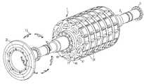
- FIG. 1is a partially exploded, perspective view of a permanent magnet rotor in accordance with the present invention
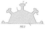
- FIG. 2is a section view of the rotor taken perpendicular to the rotor axis
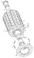
- FIG. 3is an assembled perspective view of a stage of carriers and lamination stacks surrounding the rotor shaft;
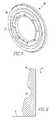
- FIG. 4is a partial cross-sectional view of an assembly of lamination stacks, spacers, and an end retainer plate in accordance with the present invention
- FIG. 6is a partial cross-sectional view of the end retainer plate of FIG. 5 .
- a shaft 3comprises the foundation of a permanent magnet rotor 1 according to this invention.
- Shaft 3is made of a non-magnetic high strength material, such a nickel cobalt alloy.
- Shaft 3has an interrupted cylindrical surface defined relative to the rotational axis of permanent magnet rotor 1 .
- Bearings 5establish the rotational axis of permanent magnet rotor 1 .
- Shaft 3has an even number of substantially identical recessed and overhung slots 7 . Slots 7 define substantially identical generally T-shaped ribs 9 with notches 11 for securing an oversized spacer 13 and dovetail surfaces 15 adjacent the slots.
- the rotor design of the present inventionincludes a plurality of stages of magnet stacks 17 held in carriers 19 with lamination stacks 21 positioned between the end walls of each carrier 19 .
- Lamination stacks 21are generally C-shaped and are comprised of a high-magnetic permeability material, such as electrical steel. Each lamination stack 21 surrounds T-shaped ribs 9 .
- Lamination stacks 21are made up of individual sheets positioned perpendicular to the axis of rotation of shaft 3 .
- the non-magnetic carriers 19 for holding permanent magnet stacks 17are positioned in each slot 7 .
- Each carrier 19carries laminated permanent magnet stacks 17 .
- Carriers 19are formed of lightweight non-magnetic structural material, such as titanium.
- the axial end walls of carrier 19have edges that are configured to abut dovetail surface 15 of T-shaped ribs 9 .
- the space between the axial end walls of carriers 19is large enough to span the axial length of magnet stacks 17 and also the axial length of lamination stacks 21 .
- the axial length of magnet stacks 17 and laminated stacks 21is identical.
- the magnets comprising magnet stacks 17are typically rare earth permanent magnets.
- the magnetsare magnetized with opposite poles at each circumferential edge face.
- the poles abutting any C-shaped lamination stack 21are of the same polarity.
- the portion of lamination stack 21 directly over each T-shaped rib 9is a magnetic pole of permanent magnet rotor 1 .
- lamination stacks 21are caused to act as one long axial stack for means of compressing.
- the first and last stages of carriers 18 and lamination stacks 21include spacers 13 that are ground so that they overhang past the carrier end walls. This creates a small gap 23 when an end retainer plate 25 is applied to each end of the assembly and drawn tight by bolting.
- end retainer plates 25are designed to include a groove 27 on a front side 29 .
- Groove 27allows the centrifugal force to deflect the top of retainer plate 25 inward towards spacers 13 in the direction designated by arrow A. This deflection keeps lamination stacks 21 in compression.
- the depth and radial position of groove 27determines how far the top of the retainer plate 25 deflects inward toward spacers 13 . Without groove 27 , retainer plates 25 would deflect away from spacers 13 and, therefore, not provide any compressive forces to lamination stacks 21 .
- End retainer plates 25may be constructed from a high-strength, lightweight, non-magnetic material such as titanium.
- the present inventionprovides a method of compressing and securing lamination stacks in a permanent magnet rotor such that movement between individual lamina is reduced. The reduction of such movement prevents individual lamina from fretting or cyclic bending which eventually leads to fatigue failure. Furthermore, the present invention includes compressing an assembly of lamination stacks and magnet carriers between end retainer plates with a grooved front side. The groove on the front side of the end retainer plates deflects the centrifugal force inward toward the spacers thus keeping the lamination stacks in a compressed state.
Landscapes
- Engineering & Computer Science (AREA)
- Power Engineering (AREA)
- Permanent Field Magnets Of Synchronous Machinery (AREA)
- Iron Core Of Rotating Electric Machines (AREA)
Abstract
Description
Claims (16)
Priority Applications (2)
| Application Number | Priority Date | Filing Date | Title |
|---|---|---|---|
| US11/267,110US7358637B2 (en) | 2005-11-04 | 2005-11-04 | Method of compressing lamination stacks for permanent magnet rotor |
| PCT/US2006/039941WO2007055861A1 (en) | 2005-11-04 | 2006-10-12 | Method of compressing lamination stacks for permanent magnet rotor |
Applications Claiming Priority (1)
| Application Number | Priority Date | Filing Date | Title |
|---|---|---|---|
| US11/267,110US7358637B2 (en) | 2005-11-04 | 2005-11-04 | Method of compressing lamination stacks for permanent magnet rotor |
Publications (2)
| Publication Number | Publication Date |
|---|---|
| US20070103023A1 US20070103023A1 (en) | 2007-05-10 |
| US7358637B2true US7358637B2 (en) | 2008-04-15 |
Family
ID=37698294
Family Applications (1)
| Application Number | Title | Priority Date | Filing Date |
|---|---|---|---|
| US11/267,110Active2026-05-28US7358637B2 (en) | 2005-11-04 | 2005-11-04 | Method of compressing lamination stacks for permanent magnet rotor |
Country Status (2)
| Country | Link |
|---|---|
| US (1) | US7358637B2 (en) |
| WO (1) | WO2007055861A1 (en) |
Cited By (26)
| Publication number | Priority date | Publication date | Assignee | Title |
|---|---|---|---|---|
| US20070247013A1 (en)* | 2006-04-20 | 2007-10-25 | Canopy Technologies, Llc | Aerodynamic insert for high speed permanent magnet motor |
| US20100032958A1 (en)* | 2008-08-06 | 2010-02-11 | Infinite Wind Energy LLC | Hyper-surface wind generator |
| US20100176600A1 (en)* | 2008-06-19 | 2010-07-15 | Rolic Invest S.Ar.L. | Wind power generator equipped with a cooling system |
| US7936102B2 (en) | 2005-11-29 | 2011-05-03 | Wilic S.Ar.L | Magnet holder for permanent magnet rotors of rotating machines |
| US20110316659A1 (en)* | 2010-06-28 | 2011-12-29 | Silviu Puchianu | Transformer testing |
| US8120198B2 (en) | 2008-07-23 | 2012-02-21 | Wilic S.Ar.L. | Wind power turbine |
| US8272822B2 (en) | 2009-01-30 | 2012-09-25 | Wilic S.Ar.L. | Wind power turbine blade packing and packing method |
| US8274170B2 (en) | 2009-04-09 | 2012-09-25 | Willic S.A.R.L. | Wind power turbine including a cable bundle guide device |
| US8310122B2 (en) | 2005-11-29 | 2012-11-13 | Wilic S.A.R.L. | Core plate stack assembly for permanent magnet rotor or rotating machines |
| US8319362B2 (en) | 2008-11-12 | 2012-11-27 | Wilic S.Ar.L. | Wind power turbine with a cooling system |
| US8358189B2 (en) | 2009-08-07 | 2013-01-22 | Willic S.Ar.L. | Method and apparatus for activating an electric machine, and electric machine |
| US8410623B2 (en) | 2009-06-10 | 2013-04-02 | Wilic S. AR. L. | Wind power electricity generating system and relative control method |
| US8541902B2 (en) | 2010-02-04 | 2013-09-24 | Wilic S.Ar.L. | Wind power turbine electric generator cooling system and method and wind power turbine comprising such a cooling system |
| US8618689B2 (en) | 2009-11-23 | 2013-12-31 | Wilic S.Ar.L. | Wind power turbine for generating electric energy |
| US8659867B2 (en) | 2009-04-29 | 2014-02-25 | Wilic S.A.R.L. | Wind power system for generating electric energy |
| US8669685B2 (en) | 2008-11-13 | 2014-03-11 | Wilic S.Ar.L. | Wind power turbine for producing electric energy |
| US8937397B2 (en) | 2010-03-30 | 2015-01-20 | Wilic S.A.R.L. | Wind power turbine and method of removing a bearing from a wind power turbine |
| US8937398B2 (en) | 2011-03-10 | 2015-01-20 | Wilic S.Ar.L. | Wind turbine rotary electric machine |
| US8957555B2 (en) | 2011-03-10 | 2015-02-17 | Wilic S.Ar.L. | Wind turbine rotary electric machine |
| US8975770B2 (en) | 2010-04-22 | 2015-03-10 | Wilic S.Ar.L. | Wind power turbine electric generator and wind power turbine equipped with an electric generator |
| US9006918B2 (en) | 2011-03-10 | 2015-04-14 | Wilic S.A.R.L. | Wind turbine |
| US9088190B2 (en) | 2011-11-30 | 2015-07-21 | Abb Research Ltd. | Electrical machines and electrical machine rotors |
| US9667109B2 (en) | 2011-03-31 | 2017-05-30 | Abb Research Ltd. | Permanent magnet electrical machine rotors with stacked annular magnets and retainers and construction methods therefor |
| US20170244292A1 (en)* | 2016-02-19 | 2017-08-24 | Moog Inc. | Rotor assembly of an electric motor |
| US20180287438A1 (en)* | 2011-05-11 | 2018-10-04 | Ge Renewable Technologies Wind B.V. | Generator Rotor, Assembly Method and Related Insertion Tool |
| US10530204B2 (en)* | 2017-06-13 | 2020-01-07 | Roopnarine | Rotor for electric machines |
Families Citing this family (7)
| Publication number | Priority date | Publication date | Assignee | Title |
|---|---|---|---|---|
| JP2006197696A (en)* | 2005-01-12 | 2006-07-27 | Toyota Motor Corp | Rotor structure of rotating electrical machine |
| JP5707863B2 (en)* | 2010-10-29 | 2015-04-30 | 株式会社明電舎 | Rotor structure of electric motor |
| JP5880136B2 (en)* | 2011-03-02 | 2016-03-08 | 日産自動車株式会社 | Rotor structure of rotating electrical machine and manufacturing method thereof |
| US10916978B2 (en)* | 2015-04-30 | 2021-02-09 | Lg Innotek Co., Ltd. | Rotor having a first core and a second core with protrusions and grooves coupling the cores to each other |
| US11515745B2 (en)* | 2018-06-14 | 2022-11-29 | Abb Schweiz Ag | Rotor with surface mounted magnets |
| FR3089712B1 (en)* | 2018-12-11 | 2023-03-10 | Ifp Energies Now | Electric machine stator with a ring formed by a plurality of stator segments |
| JP6677326B1 (en)* | 2019-01-18 | 2020-04-08 | 株式会社明電舎 | Rotating electric machine rotor |
Citations (31)
| Publication number | Priority date | Publication date | Assignee | Title |
|---|---|---|---|---|
| US464026A (en)* | 1891-12-01 | Transformer and armature-core | ||
| US891273A (en)* | 1908-01-22 | 1908-06-23 | Bullock Electric Mfg Co | Clamping means for core-plates of dynamo-electric machines. |
| US1948829A (en) | 1932-08-29 | 1934-02-27 | Fairbanks Morse & Co | Rotor for magnetos |
| US3979821A (en)* | 1975-05-09 | 1976-09-14 | Kollmorgen Corporation | Method of manufacturing rare earth permanent magnet rotor |
| US4085347A (en) | 1976-01-16 | 1978-04-18 | White-Westinghouse Corporation | Laminated stator core |
| US4358697A (en) | 1981-08-19 | 1982-11-09 | Siemens-Allis, Inc. | Two-pole permanent magnet synchronous motor rotor |
| US4433261A (en)* | 1982-03-24 | 1984-02-21 | Kabushiki Kaisha Okuma Tekkosho | Rotor for permanent magnet type synchronous motors |
| US4542313A (en) | 1983-10-03 | 1985-09-17 | Westinghouse Canada Inc. | Magnetic core spacer with means to prevent adverse vibrations thereof |
| US4585967A (en) | 1983-10-21 | 1986-04-29 | General Electric Company | Rotor of AC dynamoelectric machine with improved cooling and stability and method of making the same |
| US4631807A (en)* | 1983-06-10 | 1986-12-30 | Fanuc Ltd. | Method of manufacturing a permanent-magnet field rotor |
| US4644210A (en)* | 1985-12-12 | 1987-02-17 | Rockwell International Corporation | High speed induction motor with squirrel cage rotor |
| US4674178A (en)* | 1985-10-16 | 1987-06-23 | Sundstrand Corporation | Method of fabricating a permanent magnet rotor |
| US4728842A (en) | 1986-09-29 | 1988-03-01 | Carbet Corporation | Laminated assembly for a dynamoelectric machine and method for manufacturing laminated assemblies having ridges formed on projections which interlock with recesses of adjacent laminations |
| US4742259A (en)* | 1987-05-11 | 1988-05-03 | Franklin Electric Co., Inc. | Permanent magnet rotor for electric motor |
| US4845837A (en) | 1986-10-06 | 1989-07-11 | Emerson Electric Co. | Method of making permanent magnet assembly |
| EP0431514A1 (en) | 1989-12-08 | 1991-06-12 | Gec Alsthom Sa | Motor with magnets of the flux concentration type |
| US5554900A (en) | 1994-02-04 | 1996-09-10 | Schlenker Enterprises Ltd. | Motor including embedded permanent-magnet rotor |
| US6259180B1 (en) | 1996-07-02 | 2001-07-10 | Schlenker Enterprises, Ltd. | Motor including embedded permanent magnet rotor and method for making the same |
| US6346760B1 (en) | 2000-12-14 | 2002-02-12 | General Electric Company | Axial bolt-in cage stator frame assembly and method for assembling a stator |
| US6426576B1 (en)* | 1998-11-13 | 2002-07-30 | Conception Et Developpement Michelin S.A. | Electric machine having rotor adapted for high speed |
| US6534891B2 (en) | 1992-01-15 | 2003-03-18 | General Electric Company | High speed induction motor rotor and method of fabrication |
| US6614142B1 (en) | 1999-05-05 | 2003-09-02 | Goodrich Control Systems Limited | Rotor for an electrical machine, and an electrical machine including such a rotor |
| US6703741B1 (en) | 1999-09-20 | 2004-03-09 | Ecoair Corp. | Permanent magnet rotor portion for electric machines |
| US6741010B2 (en) | 2000-01-19 | 2004-05-25 | Rolls Royce Plc | Rotor disc assembly having rotor rim with alternate magnets and laminated pole pieces |
| US20040107562A1 (en) | 2000-01-12 | 2004-06-10 | Mol Belting Company | Electric Motor with External Rotor |
| US20040124736A1 (en) | 2002-10-18 | 2004-07-01 | Moteurs Leroy-Somer | Machine including a pulley and an electric motor for driving an elevator cable |
| US6772503B1 (en) | 2000-08-22 | 2004-08-10 | Honeywell International Inc. | Rotor assembly having bonded lamination stack |
| US20040245884A1 (en) | 1998-04-21 | 2004-12-09 | Smith James S. | High speed rotor |
| US20050034295A1 (en) | 1997-10-16 | 2005-02-17 | Meacham Walter L. | Rotatable assemblies having chemically bonded lamination stacks |
| US20050040727A1 (en) | 2003-05-19 | 2005-02-24 | Bristol Compressors | Rotor core lamination for a laminated rotor |
| US6933645B1 (en) | 2004-04-05 | 2005-08-23 | Elliott Company | Permanent magnet rotor and magnet cradle |
- 2005
- 2005-11-04USUS11/267,110patent/US7358637B2/enactiveActive
- 2006
- 2006-10-12WOPCT/US2006/039941patent/WO2007055861A1/enactiveApplication Filing
Patent Citations (36)
| Publication number | Priority date | Publication date | Assignee | Title |
|---|---|---|---|---|
| US464026A (en)* | 1891-12-01 | Transformer and armature-core | ||
| US891273A (en)* | 1908-01-22 | 1908-06-23 | Bullock Electric Mfg Co | Clamping means for core-plates of dynamo-electric machines. |
| US1948829A (en) | 1932-08-29 | 1934-02-27 | Fairbanks Morse & Co | Rotor for magnetos |
| US3979821A (en)* | 1975-05-09 | 1976-09-14 | Kollmorgen Corporation | Method of manufacturing rare earth permanent magnet rotor |
| US4085347A (en) | 1976-01-16 | 1978-04-18 | White-Westinghouse Corporation | Laminated stator core |
| US4358697A (en) | 1981-08-19 | 1982-11-09 | Siemens-Allis, Inc. | Two-pole permanent magnet synchronous motor rotor |
| US4433261A (en)* | 1982-03-24 | 1984-02-21 | Kabushiki Kaisha Okuma Tekkosho | Rotor for permanent magnet type synchronous motors |
| US4631807A (en)* | 1983-06-10 | 1986-12-30 | Fanuc Ltd. | Method of manufacturing a permanent-magnet field rotor |
| US4542313A (en) | 1983-10-03 | 1985-09-17 | Westinghouse Canada Inc. | Magnetic core spacer with means to prevent adverse vibrations thereof |
| US4585967A (en) | 1983-10-21 | 1986-04-29 | General Electric Company | Rotor of AC dynamoelectric machine with improved cooling and stability and method of making the same |
| US4674178A (en)* | 1985-10-16 | 1987-06-23 | Sundstrand Corporation | Method of fabricating a permanent magnet rotor |
| US4644210A (en)* | 1985-12-12 | 1987-02-17 | Rockwell International Corporation | High speed induction motor with squirrel cage rotor |
| US4728842A (en) | 1986-09-29 | 1988-03-01 | Carbet Corporation | Laminated assembly for a dynamoelectric machine and method for manufacturing laminated assemblies having ridges formed on projections which interlock with recesses of adjacent laminations |
| US4845837A (en) | 1986-10-06 | 1989-07-11 | Emerson Electric Co. | Method of making permanent magnet assembly |
| US4742259A (en)* | 1987-05-11 | 1988-05-03 | Franklin Electric Co., Inc. | Permanent magnet rotor for electric motor |
| EP0431514A1 (en) | 1989-12-08 | 1991-06-12 | Gec Alsthom Sa | Motor with magnets of the flux concentration type |
| US5091668A (en) | 1989-12-08 | 1992-02-25 | Gec Alsthom Sa | Motor having flux-concentrating permanent magnets |
| US6534891B2 (en) | 1992-01-15 | 2003-03-18 | General Electric Company | High speed induction motor rotor and method of fabrication |
| US5771566A (en) | 1994-02-04 | 1998-06-30 | Schlenker Enterprises Ltd. | Method of manufacturing a rotor which includes embedded permanent-magnets |
| US6601287B2 (en) | 1994-02-04 | 2003-08-05 | Stephen L. Pop, Sr. | Motor including embedded permanent-magnet rotor and method for making same |
| US5554900A (en) | 1994-02-04 | 1996-09-10 | Schlenker Enterprises Ltd. | Motor including embedded permanent-magnet rotor |
| US6259180B1 (en) | 1996-07-02 | 2001-07-10 | Schlenker Enterprises, Ltd. | Motor including embedded permanent magnet rotor and method for making the same |
| US20050034295A1 (en) | 1997-10-16 | 2005-02-17 | Meacham Walter L. | Rotatable assemblies having chemically bonded lamination stacks |
| US20040245884A1 (en) | 1998-04-21 | 2004-12-09 | Smith James S. | High speed rotor |
| US7205695B2 (en)* | 1998-04-21 | 2007-04-17 | Drs Power & Control Technologies, Inc. | High speed rotor |
| US6426576B1 (en)* | 1998-11-13 | 2002-07-30 | Conception Et Developpement Michelin S.A. | Electric machine having rotor adapted for high speed |
| US6614142B1 (en) | 1999-05-05 | 2003-09-02 | Goodrich Control Systems Limited | Rotor for an electrical machine, and an electrical machine including such a rotor |
| US6703741B1 (en) | 1999-09-20 | 2004-03-09 | Ecoair Corp. | Permanent magnet rotor portion for electric machines |
| US20040107562A1 (en) | 2000-01-12 | 2004-06-10 | Mol Belting Company | Electric Motor with External Rotor |
| US6765329B2 (en) | 2000-01-12 | 2004-07-20 | Neodrive Llc | Mounting block for electric motor with external rotor |
| US6741010B2 (en) | 2000-01-19 | 2004-05-25 | Rolls Royce Plc | Rotor disc assembly having rotor rim with alternate magnets and laminated pole pieces |
| US6772503B1 (en) | 2000-08-22 | 2004-08-10 | Honeywell International Inc. | Rotor assembly having bonded lamination stack |
| US6346760B1 (en) | 2000-12-14 | 2002-02-12 | General Electric Company | Axial bolt-in cage stator frame assembly and method for assembling a stator |
| US20040124736A1 (en) | 2002-10-18 | 2004-07-01 | Moteurs Leroy-Somer | Machine including a pulley and an electric motor for driving an elevator cable |
| US20050040727A1 (en) | 2003-05-19 | 2005-02-24 | Bristol Compressors | Rotor core lamination for a laminated rotor |
| US6933645B1 (en) | 2004-04-05 | 2005-08-23 | Elliott Company | Permanent magnet rotor and magnet cradle |
Cited By (35)
| Publication number | Priority date | Publication date | Assignee | Title |
|---|---|---|---|---|
| US7936102B2 (en) | 2005-11-29 | 2011-05-03 | Wilic S.Ar.L | Magnet holder for permanent magnet rotors of rotating machines |
| US8310122B2 (en) | 2005-11-29 | 2012-11-13 | Wilic S.A.R.L. | Core plate stack assembly for permanent magnet rotor or rotating machines |
| US7466054B2 (en)* | 2006-04-20 | 2008-12-16 | Canopy Technologies, Llc | Aerodynamic insert for high speed permanent magnet motor |
| US20070247013A1 (en)* | 2006-04-20 | 2007-10-25 | Canopy Technologies, Llc | Aerodynamic insert for high speed permanent magnet motor |
| US20100176600A1 (en)* | 2008-06-19 | 2010-07-15 | Rolic Invest S.Ar.L. | Wind power generator equipped with a cooling system |
| US10505419B2 (en) | 2008-06-19 | 2019-12-10 | Windfin B.V. | Wind power generator equipped with a cooling system |
| US8492919B2 (en) | 2008-06-19 | 2013-07-23 | Wilic S.Ar.L. | Wind power generator equipped with a cooling system |
| US9312741B2 (en) | 2008-06-19 | 2016-04-12 | Windfin B.V. | Wind power generator equipped with a cooling system |
| US8120198B2 (en) | 2008-07-23 | 2012-02-21 | Wilic S.Ar.L. | Wind power turbine |
| US8143738B2 (en) | 2008-08-06 | 2012-03-27 | Infinite Wind Energy LLC | Hyper-surface wind generator |
| US20100032958A1 (en)* | 2008-08-06 | 2010-02-11 | Infinite Wind Energy LLC | Hyper-surface wind generator |
| US8319362B2 (en) | 2008-11-12 | 2012-11-27 | Wilic S.Ar.L. | Wind power turbine with a cooling system |
| US8669685B2 (en) | 2008-11-13 | 2014-03-11 | Wilic S.Ar.L. | Wind power turbine for producing electric energy |
| US8272822B2 (en) | 2009-01-30 | 2012-09-25 | Wilic S.Ar.L. | Wind power turbine blade packing and packing method |
| US8274170B2 (en) | 2009-04-09 | 2012-09-25 | Willic S.A.R.L. | Wind power turbine including a cable bundle guide device |
| US8659867B2 (en) | 2009-04-29 | 2014-02-25 | Wilic S.A.R.L. | Wind power system for generating electric energy |
| US8410623B2 (en) | 2009-06-10 | 2013-04-02 | Wilic S. AR. L. | Wind power electricity generating system and relative control method |
| US8358189B2 (en) | 2009-08-07 | 2013-01-22 | Willic S.Ar.L. | Method and apparatus for activating an electric machine, and electric machine |
| US8810347B2 (en) | 2009-08-07 | 2014-08-19 | Wilic S.Ar.L | Method and apparatus for activating an electric machine, and electric machine |
| US8618689B2 (en) | 2009-11-23 | 2013-12-31 | Wilic S.Ar.L. | Wind power turbine for generating electric energy |
| US8541902B2 (en) | 2010-02-04 | 2013-09-24 | Wilic S.Ar.L. | Wind power turbine electric generator cooling system and method and wind power turbine comprising such a cooling system |
| US8937397B2 (en) | 2010-03-30 | 2015-01-20 | Wilic S.A.R.L. | Wind power turbine and method of removing a bearing from a wind power turbine |
| US8975770B2 (en) | 2010-04-22 | 2015-03-10 | Wilic S.Ar.L. | Wind power turbine electric generator and wind power turbine equipped with an electric generator |
| US20110316659A1 (en)* | 2010-06-28 | 2011-12-29 | Silviu Puchianu | Transformer testing |
| US8754639B2 (en)* | 2010-06-28 | 2014-06-17 | Vetco Gray Controls Limited | Transformer testing |
| US8937398B2 (en) | 2011-03-10 | 2015-01-20 | Wilic S.Ar.L. | Wind turbine rotary electric machine |
| US8957555B2 (en) | 2011-03-10 | 2015-02-17 | Wilic S.Ar.L. | Wind turbine rotary electric machine |
| US9006918B2 (en) | 2011-03-10 | 2015-04-14 | Wilic S.A.R.L. | Wind turbine |
| US9667109B2 (en) | 2011-03-31 | 2017-05-30 | Abb Research Ltd. | Permanent magnet electrical machine rotors with stacked annular magnets and retainers and construction methods therefor |
| US10958118B2 (en)* | 2011-05-11 | 2021-03-23 | Ge Renewable Technologies Wind, B.V. | Method of assembling a generator rotor of a generator |
| US20180287438A1 (en)* | 2011-05-11 | 2018-10-04 | Ge Renewable Technologies Wind B.V. | Generator Rotor, Assembly Method and Related Insertion Tool |
| US9088190B2 (en) | 2011-11-30 | 2015-07-21 | Abb Research Ltd. | Electrical machines and electrical machine rotors |
| US10581285B2 (en)* | 2016-02-19 | 2020-03-03 | Moog Inc. | Rotor assembly of an electric motor |
| US20170244292A1 (en)* | 2016-02-19 | 2017-08-24 | Moog Inc. | Rotor assembly of an electric motor |
| US10530204B2 (en)* | 2017-06-13 | 2020-01-07 | Roopnarine | Rotor for electric machines |
Also Published As
| Publication number | Publication date |
|---|---|
| US20070103023A1 (en) | 2007-05-10 |
| WO2007055861A1 (en) | 2007-05-18 |
Similar Documents
| Publication | Publication Date | Title |
|---|---|---|
| US7358637B2 (en) | Method of compressing lamination stacks for permanent magnet rotor | |
| US6933645B1 (en) | Permanent magnet rotor and magnet cradle | |
| US6967420B2 (en) | Electrical machine having a rotor specially adapted to high speeds | |
| CN101313450B (en) | Motors, rotors of such motors, applications of such rotors | |
| US7233090B2 (en) | Electric machine, in particular brushless synchronous motor | |
| EP0866540B1 (en) | A rotor for a motor or generator | |
| US7768171B2 (en) | Rotor of permanent magnet rotating electric machine | |
| US7466054B2 (en) | Aerodynamic insert for high speed permanent magnet motor | |
| EP1860755A2 (en) | Magnet retaining arrangement | |
| US4472651A (en) | Permanent magnet rotor | |
| US20030080640A1 (en) | Nonmagnetic magnet retention channel arrangement for high speed rotors | |
| EP2169806A1 (en) | Axial gap type rotating machine | |
| US5877578A (en) | Rotor disc construction for use in an electrical machine | |
| CN108696019B (en) | End plate for rotor of switched reluctance motor | |
| US10530204B2 (en) | Rotor for electric machines | |
| US9048711B2 (en) | Field structure of an electrical machine | |
| CN115398774A (en) | Stator for electrodynamic axial flux machine and electrodynamic axial flux machine | |
| US9735634B2 (en) | Split pole spoke type PM machine with enclosed magnets | |
| US20220368183A1 (en) | Rotor for a synchronous machine | |
| US6313561B1 (en) | Dynamic blocking restraint of a rotor field winding contained by a non-metallic structural rotor enclosure | |
| CN111130240A (en) | Rotor and IPM motor using same | |
| JPH10201151A (en) | Rotor for electric motor | |
| CN112260438A (en) | Motor and rotor thereof | |
| US10476328B2 (en) | Electric motor with segmented rotor | |
| US20230048820A1 (en) | Rotor core design |
Legal Events
| Date | Code | Title | Description |
|---|---|---|---|
| AS | Assignment | Owner name:CANOPY TECHNOLOGIES, LLC, PENNSYLVANIA Free format text:ASSIGNMENT OF ASSIGNORS INTEREST;ASSIGNOR:TAPPER, KEVIN LEE;REEL/FRAME:017193/0995 Effective date:20051102 | |
| AS | Assignment | Owner name:CANOPY TECHNOLOGIES, LLC, PENNSYLVANIA Free format text:CORRECTIVE ASSIGNMENT TO CORRECT THE CORRECTIVE ASSIGNMENT TO CORRECT STATE OF INCORPORATION TO DELAWARE AND TYPE OF ENTITY TO LLC. PREVIOUSLY RECORDED ON REEL 017193 FRAME 0995;ASSIGNOR:TAPPER, KEVIN LEE;REEL/FRAME:017383/0013 Effective date:20051102 | |
| STCF | Information on status: patent grant | Free format text:PATENTED CASE | |
| FPAY | Fee payment | Year of fee payment:4 | |
| AS | Assignment | Owner name:ELLIOTT COMPANY, PENNSYLVANIA Free format text:ASSIGNMENT OF ASSIGNORS INTEREST;ASSIGNOR:CANOPY TECHNOLOGIES, LLC;REEL/FRAME:027340/0304 Effective date:20111129 | |
| FPAY | Fee payment | Year of fee payment:8 | |
| MAFP | Maintenance fee payment | Free format text:PAYMENT OF MAINTENANCE FEE, 12TH YEAR, LARGE ENTITY (ORIGINAL EVENT CODE: M1553); ENTITY STATUS OF PATENT OWNER: LARGE ENTITY Year of fee payment:12 |