US7357809B2 - Chemically based vascular occlusion device deployment with gripping feature - Google Patents
Chemically based vascular occlusion device deployment with gripping featureDownload PDFInfo
- Publication number
- US7357809B2 US7357809B2US11/171,896US17189605AUS7357809B2US 7357809 B2US7357809 B2US 7357809B2US 17189605 AUS17189605 AUS 17189605AUS 7357809 B2US7357809 B2US 7357809B2
- Authority
- US
- United States
- Prior art keywords
- reactant
- expandable
- reaction chamber
- occlusion device
- gripper
- Prior art date
- Legal status (The legal status is an assumption and is not a legal conclusion. Google has not performed a legal analysis and makes no representation as to the accuracy of the status listed.)
- Expired - Fee Related, expires
Links
- 206010053648Vascular occlusionDiseases0.000titleclaimsabstractdescription35
- 208000021331vascular occlusion diseaseDiseases0.000titleclaimsabstractdescription35
- 238000006243chemical reactionMethods0.000claimsabstractdescription37
- 210000005166vasculatureAnatomy0.000claimsabstractdescription13
- 239000000376reactantSubstances0.000claimsdescription52
- LFQSCWFLJHTTHZ-UHFFFAOYSA-NEthanolChemical compoundCCOLFQSCWFLJHTTHZ-UHFFFAOYSA-N0.000claimsdescription16
- 238000000034methodMethods0.000claimsdescription16
- 239000000203mixtureSubstances0.000claimsdescription9
- 239000000463materialSubstances0.000claimsdescription7
- 229920001651CyanoacrylatePolymers0.000claimsdescription4
- MWCLLHOVUTZFKS-UHFFFAOYSA-NMethyl cyanoacrylateChemical compoundCOC(=O)C(=C)C#NMWCLLHOVUTZFKS-UHFFFAOYSA-N0.000claimsdescription4
- 239000006260foamSubstances0.000claimsdescription4
- 239000000178monomerSubstances0.000claimsdescription4
- 239000012530fluidSubstances0.000claimsdescription3
- GYVGXEWAOAAJEU-UHFFFAOYSA-Nn,n,4-trimethylanilineChemical compoundCN(C)C1=CC=C(C)C=C1GYVGXEWAOAAJEU-UHFFFAOYSA-N0.000claimsdescription3
- 229920002721polycyanoacrylatePolymers0.000claimsdescription3
- 230000009977dual effectEffects0.000claimsdescription2
- 239000002861polymer materialSubstances0.000claims1
- 239000012528membraneSubstances0.000description14
- 230000003073embolic effectEffects0.000description11
- 210000004204blood vesselAnatomy0.000description6
- 239000000835fiberSubstances0.000description6
- 239000000853adhesiveSubstances0.000description5
- 230000001070adhesive effectEffects0.000description5
- 238000010438heat treatmentMethods0.000description5
- 238000013459approachMethods0.000description4
- 229920000642polymerPolymers0.000description3
- 229920001296polysiloxanePolymers0.000description3
- 239000004830Super GlueSubstances0.000description2
- 239000004809TeflonSubstances0.000description2
- 229920006362Teflon®Polymers0.000description2
- 230000009471actionEffects0.000description2
- FGBJXOREULPLGL-UHFFFAOYSA-Nethyl cyanoacrylateChemical compoundCCOC(=O)C(=C)C#NFGBJXOREULPLGL-UHFFFAOYSA-N0.000description2
- 230000007246mechanismEffects0.000description2
- 238000012544monitoring processMethods0.000description2
- 229910001000nickel titaniumInorganic materials0.000description2
- 229920000098polyolefinPolymers0.000description2
- 239000013464silicone adhesiveSubstances0.000description2
- 230000002792vascularEffects0.000description2
- 206010002329AneurysmDiseases0.000description1
- 206010053567CoagulopathiesDiseases0.000description1
- 239000004677NylonSubstances0.000description1
- 239000004952PolyamideSubstances0.000description1
- 239000004698PolyethyleneSubstances0.000description1
- 229920005830Polyurethane FoamPolymers0.000description1
- 230000003213activating effectEffects0.000description1
- 230000009286beneficial effectEffects0.000description1
- 230000000975bioactive effectEffects0.000description1
- 239000008280bloodSubstances0.000description1
- 210000004369bloodAnatomy0.000description1
- 210000005013brain tissueAnatomy0.000description1
- 230000008859changeEffects0.000description1
- 230000035602clottingEffects0.000description1
- 230000007547defectEffects0.000description1
- 230000002950deficientEffects0.000description1
- 230000010339dilationEffects0.000description1
- 201000010099diseaseDiseases0.000description1
- 208000037265diseases, disorders, signs and symptomsDiseases0.000description1
- 230000005672electromagnetic fieldEffects0.000description1
- 239000002657fibrous materialSubstances0.000description1
- 239000006261foam materialSubstances0.000description1
- 239000000017hydrogelSubstances0.000description1
- 208000014674injuryDiseases0.000description1
- 238000004519manufacturing processMethods0.000description1
- 239000000155meltSubstances0.000description1
- 229910052751metalInorganic materials0.000description1
- 239000002184metalSubstances0.000description1
- 238000012986modificationMethods0.000description1
- 230000004048modificationEffects0.000description1
- HLXZNVUGXRDIFK-UHFFFAOYSA-Nnickel titaniumChemical compound[Ti].[Ti].[Ti].[Ti].[Ti].[Ti].[Ti].[Ti].[Ti].[Ti].[Ti].[Ni].[Ni].[Ni].[Ni].[Ni].[Ni].[Ni].[Ni].[Ni].[Ni].[Ni].[Ni].[Ni].[Ni]HLXZNVUGXRDIFK-UHFFFAOYSA-N0.000description1
- 229920001778nylonPolymers0.000description1
- 230000003287optical effectEffects0.000description1
- 229920001084poly(chloroprene)Polymers0.000description1
- 229920002647polyamidePolymers0.000description1
- -1polyethylenePolymers0.000description1
- 229920000573polyethylenePolymers0.000description1
- 229920001343polytetrafluoroethylenePolymers0.000description1
- 239000004810polytetrafluoroethyleneSubstances0.000description1
- 239000011496polyurethane foamSubstances0.000description1
- 229920000915polyvinyl chloridePolymers0.000description1
- 239000004800polyvinyl chlorideSubstances0.000description1
- 239000002243precursorSubstances0.000description1
- 230000002035prolonged effectEffects0.000description1
- 230000004044responseEffects0.000description1
- 229910001285shape-memory alloyInorganic materials0.000description1
- 239000010935stainless steelSubstances0.000description1
- 229910001220stainless steelInorganic materials0.000description1
- 238000010561standard procedureMethods0.000description1
- 239000000126substanceSubstances0.000description1
- 238000001356surgical procedureMethods0.000description1
- 230000001225therapeutic effectEffects0.000description1
- 230000008733traumaEffects0.000description1
Images


Classifications
- A—HUMAN NECESSITIES
- A61—MEDICAL OR VETERINARY SCIENCE; HYGIENE
- A61B—DIAGNOSIS; SURGERY; IDENTIFICATION
- A61B17/00—Surgical instruments, devices or methods
- A61B17/12—Surgical instruments, devices or methods for ligaturing or otherwise compressing tubular parts of the body, e.g. blood vessels or umbilical cord
- A61B17/12022—Occluding by internal devices, e.g. balloons or releasable wires
- A61B17/12131—Occluding by internal devices, e.g. balloons or releasable wires characterised by the type of occluding device
- A61B17/1214—Coils or wires
- A—HUMAN NECESSITIES
- A61—MEDICAL OR VETERINARY SCIENCE; HYGIENE
- A61B—DIAGNOSIS; SURGERY; IDENTIFICATION
- A61B17/00—Surgical instruments, devices or methods
- A61B17/12—Surgical instruments, devices or methods for ligaturing or otherwise compressing tubular parts of the body, e.g. blood vessels or umbilical cord
- A61B17/12022—Occluding by internal devices, e.g. balloons or releasable wires
- A61B2017/1205—Introduction devices
- A61B2017/12054—Details concerning the detachment of the occluding device from the introduction device
- A61B2017/12081—Details concerning the detachment of the occluding device from the introduction device detachable by inflation
Definitions
- the present inventionis related to deployment systems and methods for accurately and rapidly deploying vascular occlusion devices at a preselected location within the vascular system of a patient, and more particularly, deployment approaches that utilize a pusher having an expandable gripper which is opened by the action of an expandable chemical reaction chamber to facilitate rapid deployment of vascular occlusion devices.
- catheter delivery systemsfor positioning and deploying therapeutic devices, such as dilation balloons, stents and embolic coils, in the vasculature of the human body has become a standard procedure for treating endovascular diseases. It has been found that such devices are particularly useful in treating areas where traditional operational procedures are impossible or pose a great risk to the patient, for example in the treatment of aneurysms in cranial blood vessels. Due to the delicate tissue surrounding cranial blood vessels, especially for example brain tissue, it is very difficult and often risky to perform surgical procedures to treat such a defect. Advancements in catheter deployment systems have provided an alternative treatment in such cases. Some of the advantages of catheter delivery systems are that they provide methods for treating blood vessels by an approach that has been found to reduce the risk of trauma to the surrounding tissue, and they also allow for treatment of blood vessels that in the past would have been considered inoperable.
- these proceduresinvolve inserting the distal end of a delivery catheter into the vasculature of a patient and guiding it through the vasculature to a predetermined delivery site.
- a vascular occlusion devicesuch as an embolic coil, is attached to the end of a delivery member which pushes the coil through the catheter and out of the distal end of the catheter into the delivery site.
- Another coil deployment systememploys a pusher member having an embolic coil attached to the pusher member by a connector fiber which is capable of being broken by heat, as disclosed in Lucas et al. U.S. Pat. No. 6,478,773.
- the pusher member of this arrangementincludes an electrical resistance heating coil through which the connector fiber is passed. Electrical current is supplied to the heating coil by a power source connected to the heating coil via wires extending through an internal lumen of the pusher. The power source is activated to increase the temperature of the heating coil which breaks the connector fiber.
- One drawbackis that connecting the resistance heating coil to the power source requires running multiple wires through the pusher member. Additionally, the electrical current traveling through the wires may create stray electromagnetic fields that interfere with other surgical and/or monitoring equipment.
- a needremains for a rapid release vascular occlusion deployment system or method that does not rely on electrical equipment or a power supply, is simple to manufacture, flexible and easy to guide through the vasculature of the body, provides better control over the occlusion device, and reduces the possibility of interference with other surgical and/or monitoring equipment.
- the present inventionembodies deployment systems and methods for accurately and rapidly deploying a vascular occlusion device at a preselected site within the vasculature of a patient.
- the deployment systemmay employ an elongated flexible delivery catheter for guiding a deployment unit to the preselected site.
- the deployment unitincludes a pusher which has a gripper located at a distal end portion of the pusher.
- the gripperhas an expandable gripping element, for example a plurality of gripping jaws, for releasably attaching a vascular occlusion device, such as an embolic coil, to the deployment system.
- the pusherguides the vascular occlusion device through the delivery catheter to the preselected site.
- the delivery systemalso includes a first dispensing unit for dispensing a first reactant into the reaction chamber and a second dispensing unit for dispensing a second reactant into the reaction chamber.
- first and second reactantsWhen the first and second reactants are dispensed into the chamber, they react to form a product that has a larger volume than the combined volumes of the first and second reactants prior to reacting.
- the productpushes against the inner wall of the expandable reaction chamber which causes the reaction chamber to outwardly expand.
- the reaction chamberAs the reaction chamber expands, it pushes against the gripping element causing the gripping element to outwardly expand or open so that the gripping element releases the vascular occlusion device, thereby deploying the vascular occlusion device at the preselected location.
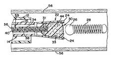
- FIG. 1is an enlarged, partially sectioned view of the vascular occlusion device deployment system of a preferred embodiment of the present invention
- FIG. 2is an enlarged partially sectioned view showing the deployment unit of FIG. 1 prior to deployment of the occlusion device;
- FIG. 3is an enlarged partially sectioned view of the deployment unit of FIG. 2 shown just after deployment of the vascular occlusion device;
- FIG. 4is an enlarged partially sectioned view of the deployment system of FIG. 1 positioned at a preselected location within the vasculature system of a patient;
- FIG. 5is an enlarged partially sectioned view of the deployment system of FIG. 1 positioned at a preselected location within the vasculature system of a patient with the vascular occlusion device extending out of the distal end of the delivery catheter;
- FIG. 6is an enlarged partially sectioned view of the deployment system of FIG. 1 shown just after the vascular occlusion device has been deployed at a preselected location within the vasculature system of a patient.
- FIG. 1generally illustrates a preferred embodiment of the vascular occlusion device deployment system of the present invention.
- the deployment systemgenerally designated at 10 , includes an elongated flexible guiding catheter 12 which is inserted into the vascular system of a patient and used to guide a deployment unit, generally designed 14 , to a preselected site in a manner generally known in the art.
- the deployment system 14includes an elongated flexible pusher or delivery tube 16 having a proximal end portion 18 and a distal end portion 20 .
- a gripper 22is located at the distal end portion 20 of the pusher 16 .
- the gripper 22includes an outwardly expandable gripping element 24 , which is generally illustrated as a plurality of jaws.
- the gripping element 24releasably engages a protruding portion or headpiece 26 of a vascular occlusion device 28 , such as an embolic coil.
- a vascular occlusion device 28such as an embolic coil
- the gripper 22may be comprised of polymer, such as FEP Teflon, PTFE Teflon, polyvinyl chloride, a polyolefin or a neoprene, or any other suitable polymer, and may be constructed as disclosed in Bennett et al. U.S. Pat. No. 5,609,608, hereby incorporated herein by reference.
- the gripper 22may be constructed of any suitable metal, or the gripper could comprise a microtube which has been slit.
- a suitable microtubemay be made of stainless steel or of a nickel-titanium alloy such as Nitinol, or other suitable material.
- the gripper 22is a separated unit which is attached to the pusher 16 in any suitable manner, for example by a silicone or cyanoacrylate adhesive.
- the gripper 22 and pusher 16could be a unitary structure.
- the occlusion device 28may be an embolic coil which may take various forms and configurations, and may also be filled with a fibrous material or may be coated with a beneficial substance, such as a biogel to promote clotting.
- the occlusion devicealso may be any other occlusion device or approach known in the art such as hydrogels, foams, bioactive coils, braids, cables, and hybrid devices.
- the reaction chamber 30is positioned within the gripper 22 .
- the reaction chamber 30which for illustrative purposes is depicted as a microballoon, is preferably comprised of an elastic membrane 31 .
- the elastic membranemay be constructed from materials that do not significantly degrade while in contact with the reactant materials or the product formed therefrom. Typically, these will be an elastic polymer, such as silicone, a polyamide, a nylon, or a polyolefin such as polyethylene.
- the reaction chamber 30includes a cavity 32 defined by the inner surface 33 of the membrane 31 .
- the delivery unit 14also includes a first dispensing unit 34 for dispensing a first reactant 36 into the cavity 32 of the reaction chamber 30 and a second dispensing unit 38 for dispensing a second reactant 40 into the cavity 32 of the reaction chamber 30 .
- the dispensing units 34 and 38comprise a dual-lumen, plunger-activated dispensing tube 39 which extends within the pusher 16 from the proximal end portion 18 to the distal end portion 20 of the pusher 16 .
- a distal end portion 41 of the dual lumen dispensing tube 39may extend through the membrane 31 of the reaction chamber 30 into the cavity 32 .
- the membrane 31 and dispensing tube 39may be attached and sealed together by an adhesive, such as a silicone or cyanoacrylate adhesive.
- an adhesivesuch as a silicone or cyanoacrylate adhesive.
- the membrane 31may be wrapped around the dispensing tube 39 and attached and sealed with a similar adhesive.
- Other connection approachescan be practiced, such as those incorporating shrink tubing or other connector members.
- the reactants 36 , 40may be dispensed from the lumens to the cavity 30 by activating a plunger 42 (which can be seen in FIG. 1 ) located at a proximal end portion of the dispensing tube 39 .
- a plunger 42which can be seen in FIG. 1
- the reactantsprior to dispensing them, are secured within the respective lumens by a breakable seal 51 , 52 , respectively.
- Such sealsshould be selected to be made of a material that does not significantly degrade while in contact with the reactant materials.
- a fluid pressure release featurecan be included to prevent the build up of fluid pressure within the reaction chamber when dispensing the reactants. This may take the form of a vent lumen 54 ( FIG. 2 ).
- first and second reactants 36 , 40are dispensed into the cavity 32 , they are mixed to produce a product 44 which has a greater volume than the combined volume of the first and second reactants prior to mixing.
- the expanding product 44pushes against the inner surface 33 of the membrane 31 , causing the membrane 31 to outwardly expand.
- the force of the expanded membrane 31 against the gripping element 24forces the gripping element to outwardly expand or open. Movement in this regard can be in a generally radial direction.
- the expanding membrane 31also may contact the headpiece 26 of the occlusion device 28 and push the headpiece 26 out of and away from the expanded gripping element 24 , when this action is desired.
- the first and second reactants 36 , 40can be any reactants that produce a product 44 having a greater volume than the original compositions.
- the first and second reactantsmay be any of the reactants disclosed in Cooke et al. WO 92/09651, hereby incorporated herein by reference, which produce a polycyanoacrylate foam.
- the first reactantis preferably a mixture of cyanoacrylate monomer and ethanol and the second reactant is preferably a mixture of ethanol and N,N-Dimethyl-p-toluidine.
- Other reactant materials, that when combined form a foam material with an increased bulk volume relative to the reactants, such as precursors for polyurethane foam,are also suitable.
- the catheter 12is inserted into the vasculature system of a patient and positioned at a preselected location within a blood vessel 56 , typically in conjunction with other devices and professional procedures as generally known in the art.
- the delivery unit 14is inserted into the catheter 12 , and as shown in FIG. 5 , once the desired location is reached, the delivery unit 14 is advanced, and/or the catheter 12 is moved in a retrograde manner, such that the delivery unit moves with respect to and within the catheter until the occlusion device 28 moves through the catheter 12 and out of the distal end of the catheter.
- the occlusion devicemay be retrieved back into the distal end of the catheter by retracting the delivery unit 14 proximally or advancing the catheter distally. Once the occlusion device has been retrieved, the catheter and/or the occlusion device may be repositioned.
- the plunger 42may be activated to dispense the first and second reactants 36 , 40 into the cavity 32 of the reaction chamber 30 .
- the first and second reactants 36 , 40mix within the cavity 32 and react to form a product 44 which has a larger volume than the combined volumes of the first and second reactants prior to mixing.
- the expanding product 44pushes against the inner wall 33 of the membrane 31 of the reaction chamber 30 , causing the membrane 31 to expand.
- the expanded membrane 31presses against the gripping element 24 outwardly expanding or opening the gripping element to release the occlusion device 28 at the preselected location within the blood vessel 56 .
- the membrane 31may simultaneously press against the headpiece 26 to push it out of and away from the gripping element 24 , thereby deploying the vascular occlusion device 28 .
Landscapes
- Health & Medical Sciences (AREA)
- Surgery (AREA)
- Life Sciences & Earth Sciences (AREA)
- Heart & Thoracic Surgery (AREA)
- Molecular Biology (AREA)
- Vascular Medicine (AREA)
- Engineering & Computer Science (AREA)
- Biomedical Technology (AREA)
- Reproductive Health (AREA)
- Medical Informatics (AREA)
- Nuclear Medicine, Radiotherapy & Molecular Imaging (AREA)
- Animal Behavior & Ethology (AREA)
- General Health & Medical Sciences (AREA)
- Public Health (AREA)
- Veterinary Medicine (AREA)
- Surgical Instruments (AREA)
- Media Introduction/Drainage Providing Device (AREA)
- Materials For Medical Uses (AREA)
Abstract
Description
Claims (21)
Priority Applications (5)
| Application Number | Priority Date | Filing Date | Title |
|---|---|---|---|
| US11/171,896US7357809B2 (en) | 2005-06-30 | 2005-06-30 | Chemically based vascular occlusion device deployment with gripping feature |
| EP06253235AEP1738694B1 (en) | 2005-06-30 | 2006-06-22 | Chemically based deployment system with gripping feature for a vascular occlusion device |
| DE602006001993TDE602006001993D1 (en) | 2005-06-30 | 2006-06-22 | Chemically based delivery device with a vascular occlusion device gripping device |
| JP2006180042AJP5259058B2 (en) | 2005-06-30 | 2006-06-29 | Chemical-based placement of a vaso-occlusive device with a grip |
| CA2551328ACA2551328C (en) | 2005-06-30 | 2006-06-29 | Chemically based vascular occlusion device deployment with gripping feature |
Applications Claiming Priority (1)
| Application Number | Priority Date | Filing Date | Title |
|---|---|---|---|
| US11/171,896US7357809B2 (en) | 2005-06-30 | 2005-06-30 | Chemically based vascular occlusion device deployment with gripping feature |
Publications (2)
| Publication Number | Publication Date |
|---|---|
| US20070005098A1 US20070005098A1 (en) | 2007-01-04 |
| US7357809B2true US7357809B2 (en) | 2008-04-15 |
Family
ID=37025140
Family Applications (1)
| Application Number | Title | Priority Date | Filing Date |
|---|---|---|---|
| US11/171,896Expired - Fee RelatedUS7357809B2 (en) | 2005-06-30 | 2005-06-30 | Chemically based vascular occlusion device deployment with gripping feature |
Country Status (5)
| Country | Link |
|---|---|
| US (1) | US7357809B2 (en) |
| EP (1) | EP1738694B1 (en) |
| JP (1) | JP5259058B2 (en) |
| CA (1) | CA2551328C (en) |
| DE (1) | DE602006001993D1 (en) |
Cited By (15)
| Publication number | Priority date | Publication date | Assignee | Title |
|---|---|---|---|---|
| US20060247572A1 (en)* | 2005-04-28 | 2006-11-02 | C. R. Bard, Inc. | Medical device removal system |
| US20070005099A1 (en)* | 2005-06-30 | 2007-01-04 | Jones Donald K | Chemically based vascular occlusion device deployment |
| US20070270930A1 (en)* | 2006-05-18 | 2007-11-22 | Schenck Jessica T | Vascular occlusion device deployment system with gripping feature opened by a collapsible reaction chamber |
| US20080125855A1 (en)* | 2002-07-19 | 2008-05-29 | Hans Henkes | Medical implant having a curlable matrix structure |
| US20080269774A1 (en)* | 2006-10-26 | 2008-10-30 | Chestnut Medical Technologies, Inc. | Intracorporeal Grasping Device |
| US20090163986A1 (en)* | 2007-12-21 | 2009-06-25 | Microvention, Inc | System And Method Of Detecting Implant Detachment |
| US20090163780A1 (en)* | 2007-12-21 | 2009-06-25 | Microvention, Inc. | System And Method For Locating Detachment Zone Of A Detachable Implant |
| US20090275971A1 (en)* | 2007-10-30 | 2009-11-05 | Boston Scientific Scimed, Inc. | Energy activated preloaded detachment mechanisms for implantable devices |
| US8679142B2 (en) | 2008-02-22 | 2014-03-25 | Covidien Lp | Methods and apparatus for flow restoration |
| US9039749B2 (en) | 2010-10-01 | 2015-05-26 | Covidien Lp | Methods and apparatuses for flow restoration and implanting members in the human body |
| US10076399B2 (en) | 2013-09-13 | 2018-09-18 | Covidien Lp | Endovascular device engagement |
| US10413310B2 (en) | 2007-10-17 | 2019-09-17 | Covidien Lp | Restoring blood flow and clot removal during acute ischemic stroke |
| US10722255B2 (en) | 2008-12-23 | 2020-07-28 | Covidien Lp | Systems and methods for removing obstructive matter from body lumens and treating vascular defects |
| US11337714B2 (en) | 2007-10-17 | 2022-05-24 | Covidien Lp | Restoring blood flow and clot removal during acute ischemic stroke |
| US12114863B2 (en) | 2018-12-05 | 2024-10-15 | Microvention, Inc. | Implant delivery system |
Families Citing this family (4)
| Publication number | Priority date | Publication date | Assignee | Title |
|---|---|---|---|---|
| US20080294189A1 (en)* | 2007-05-23 | 2008-11-27 | Moll Fransiscus L | Vein filter |
| DE102009056448B4 (en)* | 2009-12-01 | 2011-11-10 | Acandis Gmbh & Co. Kg | Delivery system for a medical functional element |
| GB2509952B (en)* | 2013-01-18 | 2015-01-28 | Cook Medical Technologies Llc | Medical device loading and carrier tool |
| CA2919868A1 (en)* | 2013-08-30 | 2015-03-05 | Arsenal Medical, Inc. | Delivery catheters for in situ forming foams |
Citations (21)
| Publication number | Priority date | Publication date | Assignee | Title |
|---|---|---|---|---|
| US5002556A (en) | 1986-11-29 | 1991-03-26 | Terumo Kabushiki Kaisha | Balloon catheter assembly |
| US5108407A (en) | 1990-06-08 | 1992-04-28 | Rush-Presbyterian St. Luke's Medical Center | Method and apparatus for placement of an embolic coil |
| WO1992009651A1 (en) | 1990-11-30 | 1992-06-11 | Chemence Limited | Polycyanoacrylate foam |
| US5609608A (en) | 1995-10-27 | 1997-03-11 | Regents Of The University Of California | Miniature plastic gripper and fabrication method |
| US5637087A (en)* | 1995-03-22 | 1997-06-10 | Abbott Laboratories | Prefilled, two-constituent syringe |
| US5989242A (en) | 1995-06-26 | 1999-11-23 | Trimedyne, Inc. | Therapeutic appliance releasing device |
| US6063100A (en) | 1998-03-10 | 2000-05-16 | Cordis Corporation | Embolic coil deployment system with improved embolic coil |
| US6068644A (en) | 1998-03-10 | 2000-05-30 | Cordis Corporation | Embolic coil hydraulic deployment system having improved catheter |
| US6238415B1 (en) | 1994-12-22 | 2001-05-29 | Target Therapeutics, Inc | Implant delivery assembly with expandable coupling/decoupling mechanism |
| US6277125B1 (en) | 1998-10-05 | 2001-08-21 | Cordis Neurovascular, Inc. | Embolic coil deployment system with retaining jaws |
| US6361547B1 (en)* | 1998-03-10 | 2002-03-26 | Cordis Corporation | Embolic coil hydraulic deployment system |
| US6478773B1 (en) | 1998-12-21 | 2002-11-12 | Micrus Corporation | Apparatus for deployment of micro-coil using a catheter |
| US6494884B2 (en) | 2001-02-09 | 2002-12-17 | Concentric Medical, Inc. | Methods and devices for delivering occlusion elements |
| US6641576B1 (en) | 1998-05-28 | 2003-11-04 | Georgia Tech Research Corporation | Devices for creating vascular grafts by vessel distension using rotatable elements |
| US20030220666A1 (en) | 2002-05-24 | 2003-11-27 | Scimed Life Systems, Inc. | Solid embolic material with variable expansion |
| US6689141B2 (en) | 2000-10-18 | 2004-02-10 | Microvention, Inc. | Mechanism for the deployment of endovascular implants |
| US6743236B2 (en) | 1998-10-05 | 2004-06-01 | Cordis Corporation | Heated vascular occlusion coil deployment system |
| US20040153025A1 (en) | 2003-02-03 | 2004-08-05 | Seifert Paul S. | Systems and methods of de-endothelialization |
| US20040218966A1 (en) | 2003-04-29 | 2004-11-04 | Fuller Douglas D. | Hand-held self-dispensing applicator |
| US20040225279A1 (en) | 2001-06-01 | 2004-11-11 | Jean Raymond | Detachable tip microcatheter for use of liquid embolic agents |
| US6871594B1 (en) | 2003-04-01 | 2005-03-29 | Randall P. Estrella | Reusable paint grenade |
Family Cites Families (1)
| Publication number | Priority date | Publication date | Assignee | Title |
|---|---|---|---|---|
| JPH07116262A (en)* | 1993-10-22 | 1995-05-09 | Olympus Optical Co Ltd | Expanding body for medical treatment |
- 2005
- 2005-06-30USUS11/171,896patent/US7357809B2/ennot_activeExpired - Fee Related
- 2006
- 2006-06-22DEDE602006001993Tpatent/DE602006001993D1/enactiveActive
- 2006-06-22EPEP06253235Apatent/EP1738694B1/ennot_activeNot-in-force
- 2006-06-29JPJP2006180042Apatent/JP5259058B2/ennot_activeExpired - Fee Related
- 2006-06-29CACA2551328Apatent/CA2551328C/ennot_activeExpired - Fee Related
Patent Citations (22)
| Publication number | Priority date | Publication date | Assignee | Title |
|---|---|---|---|---|
| US5002556A (en) | 1986-11-29 | 1991-03-26 | Terumo Kabushiki Kaisha | Balloon catheter assembly |
| US5108407A (en) | 1990-06-08 | 1992-04-28 | Rush-Presbyterian St. Luke's Medical Center | Method and apparatus for placement of an embolic coil |
| WO1992009651A1 (en) | 1990-11-30 | 1992-06-11 | Chemence Limited | Polycyanoacrylate foam |
| US6238415B1 (en) | 1994-12-22 | 2001-05-29 | Target Therapeutics, Inc | Implant delivery assembly with expandable coupling/decoupling mechanism |
| EP1537838A1 (en) | 1994-12-22 | 2005-06-08 | Boston Scientific Limited | Implant delivery assembly with expandable coupling/decoupling mechanism |
| US5637087A (en)* | 1995-03-22 | 1997-06-10 | Abbott Laboratories | Prefilled, two-constituent syringe |
| US5989242A (en) | 1995-06-26 | 1999-11-23 | Trimedyne, Inc. | Therapeutic appliance releasing device |
| US5609608A (en) | 1995-10-27 | 1997-03-11 | Regents Of The University Of California | Miniature plastic gripper and fabrication method |
| US6361547B1 (en)* | 1998-03-10 | 2002-03-26 | Cordis Corporation | Embolic coil hydraulic deployment system |
| US6068644A (en) | 1998-03-10 | 2000-05-30 | Cordis Corporation | Embolic coil hydraulic deployment system having improved catheter |
| US6063100A (en) | 1998-03-10 | 2000-05-16 | Cordis Corporation | Embolic coil deployment system with improved embolic coil |
| US6641576B1 (en) | 1998-05-28 | 2003-11-04 | Georgia Tech Research Corporation | Devices for creating vascular grafts by vessel distension using rotatable elements |
| US6743236B2 (en) | 1998-10-05 | 2004-06-01 | Cordis Corporation | Heated vascular occlusion coil deployment system |
| US6277125B1 (en) | 1998-10-05 | 2001-08-21 | Cordis Neurovascular, Inc. | Embolic coil deployment system with retaining jaws |
| US6478773B1 (en) | 1998-12-21 | 2002-11-12 | Micrus Corporation | Apparatus for deployment of micro-coil using a catheter |
| US6689141B2 (en) | 2000-10-18 | 2004-02-10 | Microvention, Inc. | Mechanism for the deployment of endovascular implants |
| US6494884B2 (en) | 2001-02-09 | 2002-12-17 | Concentric Medical, Inc. | Methods and devices for delivering occlusion elements |
| US20040225279A1 (en) | 2001-06-01 | 2004-11-11 | Jean Raymond | Detachable tip microcatheter for use of liquid embolic agents |
| US20030220666A1 (en) | 2002-05-24 | 2003-11-27 | Scimed Life Systems, Inc. | Solid embolic material with variable expansion |
| US20040153025A1 (en) | 2003-02-03 | 2004-08-05 | Seifert Paul S. | Systems and methods of de-endothelialization |
| US6871594B1 (en) | 2003-04-01 | 2005-03-29 | Randall P. Estrella | Reusable paint grenade |
| US20040218966A1 (en) | 2003-04-29 | 2004-11-04 | Fuller Douglas D. | Hand-held self-dispensing applicator |
Non-Patent Citations (1)
| Title |
|---|
| European Search Report in EP 06 25 3235, dated Oct. 24, 2006. |
Cited By (35)
| Publication number | Priority date | Publication date | Assignee | Title |
|---|---|---|---|---|
| US11426293B2 (en) | 2002-07-19 | 2022-08-30 | Ussc Medical Gmbh | Medical implant |
| US10342683B2 (en) | 2002-07-19 | 2019-07-09 | Ussc Medical Gmbh | Medical implant having a curlable matrix structure and method of use |
| US20080125855A1 (en)* | 2002-07-19 | 2008-05-29 | Hans Henkes | Medical implant having a curlable matrix structure |
| US8632584B2 (en) | 2002-07-19 | 2014-01-21 | Dendron Gmbh | Medical implant having a curlable matrix structure and method of use |
| US20060247572A1 (en)* | 2005-04-28 | 2006-11-02 | C. R. Bard, Inc. | Medical device removal system |
| US8025668B2 (en)* | 2005-04-28 | 2011-09-27 | C. R. Bard, Inc. | Medical device removal system |
| US7780695B2 (en)* | 2005-06-30 | 2010-08-24 | Codman & Shurtleff, Inc. | Chemically based vascular occlusion device deployment |
| US20100286723A1 (en)* | 2005-06-30 | 2010-11-11 | Codman & Shurtleff, Inc. | Chemically based vascular occlusion device deployment |
| US8206413B2 (en) | 2005-06-30 | 2012-06-26 | Codman & Shurtleff, Inc. | Chemically based vascular occlusion device deployment |
| US20070005099A1 (en)* | 2005-06-30 | 2007-01-04 | Jones Donald K | Chemically based vascular occlusion device deployment |
| US8721701B2 (en)* | 2006-05-18 | 2014-05-13 | DePuy Synthes Products, LLC | Vascular occlusion device deployment system with gripping feature opened by a collapsible reaction chamber |
| US20070270930A1 (en)* | 2006-05-18 | 2007-11-22 | Schenck Jessica T | Vascular occlusion device deployment system with gripping feature opened by a collapsible reaction chamber |
| US20100331853A1 (en)* | 2006-10-26 | 2010-12-30 | Chestnut Medical Technologies, Inc. | Intracorporeal grasping device |
| US8298244B2 (en) | 2006-10-26 | 2012-10-30 | Tyco Healtcare Group Lp | Intracorporeal grasping device |
| US20080269774A1 (en)* | 2006-10-26 | 2008-10-30 | Chestnut Medical Technologies, Inc. | Intracorporeal Grasping Device |
| US10413310B2 (en) | 2007-10-17 | 2019-09-17 | Covidien Lp | Restoring blood flow and clot removal during acute ischemic stroke |
| US11337714B2 (en) | 2007-10-17 | 2022-05-24 | Covidien Lp | Restoring blood flow and clot removal during acute ischemic stroke |
| US20090275971A1 (en)* | 2007-10-30 | 2009-11-05 | Boston Scientific Scimed, Inc. | Energy activated preloaded detachment mechanisms for implantable devices |
| US20090163986A1 (en)* | 2007-12-21 | 2009-06-25 | Microvention, Inc | System And Method Of Detecting Implant Detachment |
| US8460332B2 (en) | 2007-12-21 | 2013-06-11 | Microvention, Inc. | System and method of detecting implant detachment |
| US8192480B2 (en) | 2007-12-21 | 2012-06-05 | Microvention, Inc. | System and method of detecting implant detachment |
| US10299755B2 (en) | 2007-12-21 | 2019-05-28 | Microvention, Inc. | System and method for locating detachment zone of a detachable implant |
| US9242070B2 (en) | 2007-12-21 | 2016-01-26 | MicronVention, Inc. | System and method for locating detachment zone of a detachable implant |
| US20090163780A1 (en)* | 2007-12-21 | 2009-06-25 | Microvention, Inc. | System And Method For Locating Detachment Zone Of A Detachable Implant |
| US9161766B2 (en) | 2008-02-22 | 2015-10-20 | Covidien Lp | Methods and apparatus for flow restoration |
| US10456151B2 (en) | 2008-02-22 | 2019-10-29 | Covidien Lp | Methods and apparatus for flow restoration |
| US8940003B2 (en) | 2008-02-22 | 2015-01-27 | Covidien Lp | Methods and apparatus for flow restoration |
| US8679142B2 (en) | 2008-02-22 | 2014-03-25 | Covidien Lp | Methods and apparatus for flow restoration |
| US11529156B2 (en) | 2008-02-22 | 2022-12-20 | Covidien Lp | Methods and apparatus for flow restoration |
| US10722255B2 (en) | 2008-12-23 | 2020-07-28 | Covidien Lp | Systems and methods for removing obstructive matter from body lumens and treating vascular defects |
| US9039749B2 (en) | 2010-10-01 | 2015-05-26 | Covidien Lp | Methods and apparatuses for flow restoration and implanting members in the human body |
| US10426644B2 (en) | 2010-10-01 | 2019-10-01 | Covidien Lp | Methods and apparatuses for flow restoration and implanting members in the human body |
| US10076399B2 (en) | 2013-09-13 | 2018-09-18 | Covidien Lp | Endovascular device engagement |
| US11304712B2 (en) | 2013-09-13 | 2022-04-19 | Covidien Lp | Endovascular device engagement |
| US12114863B2 (en) | 2018-12-05 | 2024-10-15 | Microvention, Inc. | Implant delivery system |
Also Published As
| Publication number | Publication date |
|---|---|
| EP1738694A1 (en) | 2007-01-03 |
| DE602006001993D1 (en) | 2008-09-11 |
| US20070005098A1 (en) | 2007-01-04 |
| JP2007014763A (en) | 2007-01-25 |
| JP5259058B2 (en) | 2013-08-07 |
| CA2551328A1 (en) | 2006-12-30 |
| CA2551328C (en) | 2014-10-07 |
| EP1738694B1 (en) | 2008-07-30 |
Similar Documents
| Publication | Publication Date | Title |
|---|---|---|
| CA2551328C (en) | Chemically based vascular occlusion device deployment with gripping feature | |
| US7553321B2 (en) | Chemically based vascular occlusion device deployment | |
| US8721701B2 (en) | Vascular occlusion device deployment system with gripping feature opened by a collapsible reaction chamber | |
| US8206413B2 (en) | Chemically based vascular occlusion device deployment | |
| US6102932A (en) | Intravascular device push wire delivery system | |
| CA2411164C (en) | Reloadable sheath for catheter system for deploying vasoocclusive devices | |
| EP2001543B1 (en) | Heat detachable coil | |
| US20070270903A1 (en) | Stretch resistant embolic coil delivery system with combined mechanical and pressure release mechanism | |
| US20080269719A1 (en) | Implantable medical device delivery system with a frangible portion and methods of making and using the same | |
| EP1738693B1 (en) | Laser-based vascular occlusion device detachment system | |
| US20050149108A1 (en) | Implant delivery and detachment system and method | |
| US7819889B2 (en) | Detachable introducer for a medical device deployment system | |
| JP2006305386A (en) | Mechanism for deployment of endovascular implants | |
| JP2007160086A (en) | Embolic device delivery system | |
| US20060241682A1 (en) | Intravascular device push wire delivery system | |
| EP1307145B1 (en) | Intravascular delivery system | |
| US8920457B2 (en) | Modified headpiece for hydraulic coil deployment system | |
| US7670353B2 (en) | Modified headpiece for hydraulic coil deployment system |
Legal Events
| Date | Code | Title | Description |
|---|---|---|---|
| AS | Assignment | Owner name:CORDIS DEVELOPMENT CORPORATION, FLORIDA Free format text:ASSIGNMENT OF ASSIGNORS INTEREST;ASSIGNORS:JONES, DONALD K.;MITELBERG, VLADIMIR;REEL/FRAME:016687/0041 Effective date:20051012 | |
| AS | Assignment | Owner name:CORDIS NEUROVASCULAR, INC., FLORIDA Free format text:ASSIGNMENT OF ASSIGNORS INTEREST;ASSIGNOR:CORDIS DEVELOPMENT CORPORATION;REEL/FRAME:017961/0930 Effective date:20051012 | |
| AS | Assignment | Owner name:CODMAN & SHURTLEFF, INC., MASSACHUSETTS Free format text:MERGER;ASSIGNOR:CORDIS NEUROVASCULAR, INC.;REEL/FRAME:023032/0233 Effective date:20081216 Owner name:CODMAN & SHURTLEFF, INC.,MASSACHUSETTS Free format text:MERGER;ASSIGNOR:CORDIS NEUROVASCULAR, INC.;REEL/FRAME:023032/0233 Effective date:20081216 | |
| FPAY | Fee payment | Year of fee payment:4 | |
| REMI | Maintenance fee reminder mailed | ||
| LAPS | Lapse for failure to pay maintenance fees | ||
| STCH | Information on status: patent discontinuation | Free format text:PATENT EXPIRED DUE TO NONPAYMENT OF MAINTENANCE FEES UNDER 37 CFR 1.362 | |
| FP | Expired due to failure to pay maintenance fee | Effective date:20160415 |