US7357804B2 - Quick-release drill-guide assembly for bone-plate - Google Patents
Quick-release drill-guide assembly for bone-plateDownload PDFInfo
- Publication number
- US7357804B2 US7357804B2US10/639,515US63951503AUS7357804B2US 7357804 B2US7357804 B2US 7357804B2US 63951503 AUS63951503 AUS 63951503AUS 7357804 B2US7357804 B2US 7357804B2
- Authority
- US
- United States
- Prior art keywords
- drill
- guide assembly
- recited
- bushing
- barrel
- Prior art date
- Legal status (The legal status is an assumption and is not a legal conclusion. Google has not performed a legal analysis and makes no representation as to the accuracy of the status listed.)
- Expired - Lifetime, expires
Links
Images


Classifications
- A—HUMAN NECESSITIES
- A61—MEDICAL OR VETERINARY SCIENCE; HYGIENE
- A61B—DIAGNOSIS; SURGERY; IDENTIFICATION
- A61B17/00—Surgical instruments, devices or methods
- A61B17/16—Instruments for performing osteoclasis; Drills or chisels for bones; Trepans
- A61B17/17—Guides or aligning means for drills, mills, pins or wires
- A61B17/1728—Guides or aligning means for drills, mills, pins or wires for holes for bone plates or plate screws
- A—HUMAN NECESSITIES
- A61—MEDICAL OR VETERINARY SCIENCE; HYGIENE
- A61B—DIAGNOSIS; SURGERY; IDENTIFICATION
- A61B17/00—Surgical instruments, devices or methods
- A61B17/16—Instruments for performing osteoclasis; Drills or chisels for bones; Trepans
- A—HUMAN NECESSITIES
- A61—MEDICAL OR VETERINARY SCIENCE; HYGIENE
- A61B—DIAGNOSIS; SURGERY; IDENTIFICATION
- A61B17/00—Surgical instruments, devices or methods
- A61B17/16—Instruments for performing osteoclasis; Drills or chisels for bones; Trepans
- A61B17/17—Guides or aligning means for drills, mills, pins or wires
- A61B17/1739—Guides or aligning means for drills, mills, pins or wires specially adapted for particular parts of the body
- A61B17/1757—Guides or aligning means for drills, mills, pins or wires specially adapted for particular parts of the body for the spine
- A—HUMAN NECESSITIES
- A61—MEDICAL OR VETERINARY SCIENCE; HYGIENE
- A61B—DIAGNOSIS; SURGERY; IDENTIFICATION
- A61B17/00—Surgical instruments, devices or methods
- A61B2017/0042—Surgical instruments, devices or methods with special provisions for gripping
Definitions
- the present inventionrelates to a surgical drill-guide assembly that can be releasably attached to a part of a bone-fixation system, for example, a bone plate.
- the surgical drill-guide assembly of the present inventionis used for example, to guide a drill-bit, screw, bone fastener, or other instrument or fastener into bone or other tissue.
- the use of surgical fixation plates for a variety of orthopedic applicationsis widely accepted.
- the platesare used by surgeons or users to stabilize, mend, or align a patient's bone as well as alter compression of patient's bones. Plates are typically fastened to the bones with a plurality of fasteners such as screws that are installed through holes in the plate. Proper orientation and alignment of fasteners and secure surgical fixation of the plates can mitigate some of the potential future complications after implantation.
- Bone plates used, for example, in spinal applicationsmust be installed with special care, as the plates may be used for long-term, intervertebral fixation, bone-fragment fixation, and/or anterior decompression in the cervical region of the spine.
- the margin for error in spinal surgeryis quite small, particularly because of the sensitivity of the spinal cord and the risk inherent with invasive procedures around the spinal cord.
- the dimensions of vertebral bone available for setting fastenersare fairly limiting.
- Each fixation screwshould properly align with its associated plate hole so that each screw is seated correctly with the plate and enters the bone at an appropriate angle. Any misalignment of the screw within the plate hole risks tissue damage and spinal cord injury. In addition, improperly seated screws may result in an unstable or insecure connection of the plate to the bony material, thus potentially defeating the usefulness of the plate. Locking plates, in particular, demand precise fastener alignment.
- the present inventionrelates to a drill-guide assembly, which in one embodiment comprises an alignment drill-barrel, a bushing, a dual-arm support, a ratchet-gear mechanism, a handle member, and a release knob.
- the alignment drill-barrelhas a proximal end and a forward-end also called the distal end.
- the proximal end of the alignment drill-barrelpreferably has two ridges, and the distal end is generally tapered.
- the alignment drill-barrelis configured to receive and guide a drill-bit, bone tap, screw, bone fastener or other instrument into bone or other tissue.
- the alignment drill-barrelpreferably allows for the passage of fixation pins or bone screws, drills, taps, or awls through it in a predetermined trajectory.
- the bushingpreferably has a radially expandable forward-end and a proximal end, wherein the forward-end is configured to engage a fastener hole in a bone-plate.
- the radially expandable forward end of the bushingpreferably has a plurality of finger portions.
- the radially expandable forward endalso preferably has a shoulder, neck, and an outwardly projecting rim disposed forward of the neck.
- the bushingis configured to slidably receive the alignment drill-barrel. Sliding the alignment drill-barrel toward the forward end of the bushing preferably expands the forward end of the bushing to secure the drill-guide assembly in a bone-plate.
- the dual-arm supportin one embodiment is generally “L-shaped” with the two ends of the “L” forming an obtuse angle.
- the dual-arm supportpreferably has a space provided in its center region.
- the end portionwhich is generally horizontally disposed, comprises a pivot-hole for inserting a pivot screw.
- the dual-arm supportis immovably or fixedly connected to the proximal end of the bushing, while at its other end, the dual-arm support is immovably connected to the front end of the handle member.
- the handle memberin an exemplary embodiment has a front end and a back end. It is generally oval shaped with broad grooves on top to provide better grip for the surgeon or user using the drill-guide assembly.
- the handlemay be hollow or solid depending upon design choice.
- the ratchet-gear mechanism in one embodimentis generally “Y-shaped” and is housed within the space of the dual-arm support. At one end, the first leg of the ratchet-gear mechanism is pivotably connected to the dual-arm support at a pivot-point. That end of the first leg further extends beyond the pivot point forming a C-shaped vice-grip.
- the C-shaped vice-gripattaches to the alignment drill-barrel.
- the C-shaped vice-gripgrasps the alignment drill-barrel in between the two ridges at the proximal end.
- the plane of the C-shaped vice-gripis generally perpendicular to the axial direction of the alignment drill-barrel, and the bushing.
- the second leg of the Y-shaped ratchet-gear mechanismcomprises pawls on the outer side which permit incremental swiveling of the ratchet-gear mechanism in a plane perpendicular to the plane of C-shaped vice-grip.
- the tail-end of the Y-shaped ratchet-gear mechanismacts as a trigger and generally moves in a rotational motion relative to the pivot point in a direction toward or away from the handle member. Movement of the ratchet-gear mechanism, and particularly the C-shaped vice grip, slides the alignment drill-barrel relative to the bushing.
- the release knob in an exemplary embodimenthas a curved longitudinal member with a base.
- the basehas serrations on one side of its circumferential border and a hole on the other side.
- the release knobis pivoted through the hole in the base about a dowel pin that is attached to the dual-arm support.
- the distal end of the alignment drill-barrelis urged into the bushing which in turn, expands the forward-end of the bushing, thus locking the bushing within the fastener hole of the bone-plate.
- the bushingis configured and dimensioned to expand within the bone-plate fastener holes such that it is releasably locked to the bone-plate.
- the alignment drill-barrelpreferably self-aligns with the axis of the fastener hole in the plate.
- the pawlsare disengaged from the serrations, and the Y-shaped ratchet-gear mechanism returns to an unactuated position, preferably by action of a biasing member such as a spring.
- the Y-shaped ratchet-gear mechanismin turn, through its C-shaped vice-grip moves the alignment drill-barrel in a longitudinal direction along its axis, away from the fingers. As a result, the bushing assumes a retracted position thereby disengaging the fastener hole.
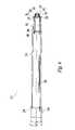
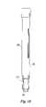
- FIG. 1is a perspective view of the drill-guide assembly
- FIG. 2is a cross-sectional view of the alignment drill-barrel in accordance with a preferred embodiment of the present invention
- FIG. 3is a partial cross-sectional view of the alignment drill-barrel in accordance with another preferred embodiment of the present invention.
- FIG. 4is a cross-sectional view of an embodiment of the bushing
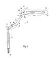
- FIG. 5is a side view of the dual-arm support attached to the bushing and handle member
- FIG. 6is a perspective view of the Y-shaped ratchet-gear mechanism
- FIG. 6 ais a side view of the Y-shaped ratchet-gear mechanism
- FIG. 6 bis a perspective view of the drill-guide assembly showing the ratchet-gear mechanism connected to the dual-arm support;
- FIG. 7is a side view of the release knob
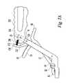
- FIG. 7 ais a perspective view of the ratchet-gear mechanism engaging the release knob
- FIG. 8is a side view of the handle member of the drill-guide assembly
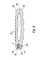
- FIG. 9is a side view of the bushing with fingers in retracted position
- FIG. 10is a side view of the bushing with fingers in expanded position.
- FIG. 11is a perspective view of the drill-guide assembly locked to a bone-plate.
- FIG. 1there is shown an exemplary surgical drill-guide assembly 5 , which is adapted for use with a cervical spine-locking bone plate having a plurality of fastener holes. While the surgical drill-guide assembly is described in conjunction with a cervical locking plate it will be appreciated that the reference to a cervical locking plate is only exemplary, and that the surgical drill-guide assembly can be used with a variety of bone plates, including a locking and a nonlocking bone-plate as well as for example, bone plates for long bones, maxillofacial applications, etc.
- the drill-guide assembly 5can be secured or locked into a fastener hole in a bone plate. Locking or securing may facilitate precision in the surgical procedure, for example, drilling or fastening screws or other similar fasteners. Moreover, the drill-guide can be quickly detached and released from the bone-plate improving the speed of surgical procedures involving drilling or similar procedures.
- Drill-guide assembly 5includes an alignment assembly 15 , a release knob 100 , a handle member 250 , a ratchet-gear mechanism 50 , and a dual-arm support 10 .
- the alignment assembly 15comprises an alignment drill-barrel 150 and a bushing 200 .
- a surgeon or a usercan releasably attach the alignment assembly 15 in the fastener hole 352 of a bone-plate 350 .
- a drill-bit or other such instrumentcan be inserted into and through the alignment assembly 15 .
- the alignment drill-barrel 150preferably has a through bore 185 from its proximal end 174 to its distal end 172 .
- a drill-bit or other instrumentmay be inserted through the bore 185 .
- the drill-barrelcomprises a first hollow cylindrical section 156 with an annular diameter of x 12 , a second hollow cylindrical section 158 with an inside annular diameter of x 18 , and a third hollow cylindrical section 160 with an inside annular diameter of x 24 , wherein x 24 is smaller than x 18 , and x 18 is smaller than x 12 .
- the outside surface of the alignment drill-barrel 150comprises a shoulder 162 and a shoulder 164 wherein the outside diameter of the first section 166 is x 14 which is greater than the outside diameter x 20 of the second section 168 .
- x 14has an exemplary diameter of 3 mm to 10 mm, preferably about 8 mm.
- the third section 170is a conical section that tapers from an outside diameter x 22 at shoulder 164 to a diameter x 26 at the distal end 172 .
- the proximal end 174 of the alignment drill-barrel 150preferably has first circular ridge 152 and second circular ridge 154 .
- the first and the second circular ridges 152 and 154respectively, have an outside diameter x 16 .
- first circular ridge 152is flush with the proximal end 174 of the alignment drill-barrel 150 .
- the conical section 170tapers from an outside diameter x 22 at the transition 164 to an outside diameter x 26 at end 172 .
- inner diameter x 24is constant along the length of conical section 170 of alignment drill-barrel 150 as defined along center line 180 .
- alignment drill-barrel 150is hollow with a cylindrical section 182 and a tapered, conical section 184 to facilitate movement of alignment drill-barrel 150 within bushing 200 .
- Cylindrical section 182has outside diameter x 5
- conical section 184tapers from an outside diameter x 5 at the transition 186 to an outside diameter x 6 at the distal end 188 .
- inner diameter x 7is constant along the length of alignment drill-barrel 150 as defined along center line 190 .
- Bushing 200coaxially receives alignment drill-barrel 150 about a central line 240 .
- bushing 200is substantially symmetrical about line 240 .
- the forward end 222 of bushing 200is preferably comprised of longitudinally extending fingers 210 .
- Individual fingers 210are separated by slits 204 extending longitudinally between adjacent fingers 210 .
- Slits 204as shown, for example, in FIG. 4 , may include a circular portion 206 that serves to minimize stress concentration when fingers 210 are flexed.
- Fingers 210are resiliently biased inwardly and naturally assume an inward disposition when in a relaxed state.
- the fingers 210form a radially expandable circumferential neck 208 .
- At the back end of and adjacent to neck 208is preferably a shoulder 212 .
- neck 208spans a length that is slightly longer than the thickness of the fastener hole wall from the bone-side surface to the top surface of a bone-plate.
- neck 208can be inserted into the bone-plate fastener hole 352 and the fingers 210 expanded to secure the bushing 200 to the plate. More particularly, movement of alignment drill-barrel 150 within bushing 200 expands fingers 210 to secure the bushing 200 to the bone plate. In this manner, the drill-guide assembly can be secured to the plate, restricting relative movement.
- fingers 210 forming a radially expandable rim 214are provided at the front end of and adjacent to neck 208 .
- the distal end 222 of the bushing 200may not contain the rim 214 , the neck 208 or the shoulder 212 , but instead has a tapered end with the inner and the outer diameter of the tapered end decreasing from point 220 shown in FIG. 4 .
- the taperis such that it fits freely through a fastener hole in a bone plate.
- no rimmay be used.
- the several portions of bushing 200i.e., the neck 208 , the shoulder 212 , and the rim 214 , are preferably a single piece of material of unitary construction.
- fingers 210need not include a shoulder, neck, and/or a rim. Instead, for example, a small pin may be used to secure the bushing to the plate.
- the inward bias of fingers 210is selected to produce the desired friction with the bone-plate 350 so that the fingers 210 fit snugly within the bone-plate fastener hole 352 , preferably allowing operation of handle member 250 with only one hand.
- Alternative resiliency for fingers 210may be varied to suit the purpose of the design.
- bushing 200has one or more longitudinal slots on its side 224 in axial direction 240 just above the circular portion 206 . These slots provide better cleaning during autoclave or other disinfection and/or cleaning procedures.
- bushing 200has a circumferential ridge 218 with an outer diameter x 3 , and a region 216 has an outer diameter x 4 .
- x 4has an exemplary dimension of 4 mm to 20 mm, preferably about 8 mm.
- dual-arm support 10connects the handle member 250 to the alignment assembly 15 . More specifically, in the exemplary embodiments of FIGS. 1 and 2 , the dual-arm support 10 is fixedly connected at its end to the proximal end 174 of the alignment assembly 15 . Dual-arm support 10 preferably is generally “L-shaped” with first part 14 connected to bushing 200 . More specifically, end 12 of dual-arm support 10 is attached to ridge 218 at the proximal end 242 of the bushing 200 .
- the dual-arm support 10is preferably fixed with the bushing 200 by welding. In an alternative embodiment, friction fitting, press fitting, and such can be used. Outer diameter x 3 of ridge 218 is about the same size as inner diameter x 1 of the clamp 12 of the dual-arm support 10 .
- Bushing 200may also be fixed to dual-arm support 10 by releasable fastener means.
- First part 14is generally perpendicular to the axial direction of the alignment assembly 15 or the bushing 200 .
- the second part 16 of the dual-arm support 10preferably forms an obtuse angle ⁇ d1 with the first part 14 of the dual-arm support 10 .
- ⁇ d1may range from about 90° to about 180°, and more preferably from about 105° to about 135°.
- Dual-arm support 10 and handle member 250are fixedly connected by a dowel pin 20 at the front end of the handle member 250 , so that they are immovable with respect to each other.
- handle member 250is located remotely from the drilling site, thereby increasing visibility near the locking bone plate 350 .
- the second part 16 of the dual-arm support 10may be attached to the first part 14 by a dowel pin 18 , or the dual-arm support 10 may be an integral, monolithic construction.
- the second part 16 of the dual-arm support 10also forms an obtuse angle ⁇ d2 with the handle member 250 .
- ⁇ d2may range from about 90° to about 180°, and more preferably from about 105° to about 135°.
- the handle member 250 and the dual-arm support 10generally form an “S” shape or a zigzag shape, and in a preferred embodiment, the longitudinal axis 24 of the first part 14 and the longitudinal axis 26 of the second part 16 lie in the same plane.
- the longitudinal axis 280 of the handle member 250also preferably lies in the same plane as the longitudinal axis 24 of the first part 14 and the longitudinal axis 26 of the second part 16 of the dual-arm support 10 .
- the longitudinal axis 24 of the first-part 14 of the dual-arm support 10is generally parallel with the longitudinal axis 280 of the handle member 250 .
- the ratchet-gear mechanism 50allows the user to manipulate the locking and release of the drill-guide assembly 5 with the bone-plate 350 by engagement and disengagement, respectively, of the pawls 58 with the serrations 102 .
- the ratchet-gear mechanism 50in a preferred embodiment is generally “Y-shaped” with a first leg 52 , a second leg 54 , and a tail 56 .
- the first leg 52 of the ratchet-gear mechanismcomprises a generally C-shaped vice-grip 60 at its end, and a pivot hole 62 for insertion of a pivot screw 64 .
- the C-shaped vice-grip 60grips the alignment drill-barrel 150 in between the first ridge 152 and second ridge 154 (see also FIG. 2 ) located at the end 174 of the drill-barrel 150 . As shown in FIG.
- the plane of the C-shaped vice-grip 60 that forms an anterior portion of the first leg 52 of the Y-shaped ratchet-gear mechanism 50makes an acute angle ⁇ d with the longitudinal axis 64 of the first leg 52 of the Y-shaped ratchet-gear mechanism 50 .
- pivot screw 64 and hole 62are located at the point of inflexion between the longitudinal first leg 52 and the C-shaped vice grip 60 . This pivot mechanism 62 helps the movement of the alignment drill-barrel 150 .
- the acute angleis from about 25° to about 45°.
- the acute angle ⁇ dis such that when the ratchet-gear mechanism 50 is completely disengaged from the serrations 102 of the release knob 100 , the alignment drill-barrel 150 can be removed from the bushing 200 in a longitudinal direction away from the fingers 210 by moving the ratchet-gear mechanism 50 in a direction away from the handle member 250 , about the pivot screw 64 .
- ⁇ dmay be 0° to 90°, with an exemplary dimension of 60°.
- the second leg 54 of the Y-shaped ratchet-gear mechanism 50comprises horizontal pawls 58 which engage serrations 102 at the end of the release knob 100 .
- the tail 56 of the Y-shaped ratchet-gear mechanism 50acts as a trigger for a user to apply a force to actuate movement of the alignment drill-barrel 150 .
- the release knob 100is pivoted about a dowel pin 106 which is inserted through the dowel pin hole 104 in the release knob 100 , and the release knob hole 142 in the second part 16 of the dual-arm support 10 .
- the serrations 102 on the surface of the release knob 100can engage with the pawls 58 on the second leg 54 of the Y-shaped ratchet-gear mechanism, when the tail 56 (trigger) of the Y-shaped ratchet-mechanism is pressed or moved in a direction toward the handle member 250 .
- the release knob 100has a rubber sleeve 106 or a sleeve made from a material which provides a firm traction when the surgeon or the user presses the release knob 100 .
- the surface of the release knobmay have surface texturing to increase the traction when a surgeon or a user manipulates the release knob 100 .
- Handle member 250is shown. Handle member 250 is generally oval shaped with broad grooves 252 on top to provide better grip to the surgeon or user when using the drill-guide assembly 5 .
- the first cavity 256has an axis along line 260 and the second cavity 258 has an axis along line 270 .
- the first cavity 256houses compression spring 272 and the second cavity 258 houses the dual-arm support 10 , or more specifically the second part 16 of the dual-arm support 10 .
- the second part 16 of the dual-arm support 10is fixed to the handle member 250 by a dowel pin 20 .
- the dowel pin 20in a preferred embodiment, is generally perpendicular to the axis 280 of the handle member 250 .
- Exemplary dimensions of the handleare 100 to 150 mm long with a width at the widest point of 15 mm to 40 mm.
- the ratchet-gear mechanism 50When a surgeon or a user presses the trigger 56 , toward handle member 250 , the ratchet-gear mechanism 50 swivels. Due to the movement of the Y-shaped ratchet-gear mechanism 50 in the direction of the handle member 250 , the alignment drill-barrel 150 moves the bushing 200 in the downward direction toward the bone-plate 350 . Due to the conical shape 170 of the alignment drill-barrel 150 ( FIG. 2 ), the fingers 210 on the bushing 200 expand in an outward direction as the front end 172 of alignment drill-barrel 150 approaches the front edge 214 of bushing 200 .
- the drill-guide assembly 5locks to the bone-plate 350 .
- a surgical drill-bit 400 or any other appropriate bit, screw, tap, awl, or such device,can be inserted through the alignment drill-barrel 150 .
- Alignment drill-barrel 150is configured and dimensioned to be slidably received within bushing 200 .
- the alignment drill-barrel 150 and bushing 200cooperate to permit drill-guide assembly 5 to lock to a bone plate 350 .
- the conical section 184 of the alignment drill-barrel 150cooperates with fingers 210 of bushing 200 to expand fingers 210 when the alignment drill-barrel 150 is moved into a locked position.
- the conical section 184 of alignment drill-barrel 150pushes outwardly against the inner surface of the bushing 200 as alignment drill-barrel 150 is moved forward to expand the forward end 214 of the bushing 200 .
- the conical sectionmates with and pushes against the inner surface of the bushing 200 forward of circular portion 206 of slits 204 in fingers 210 , to push the fingers 210 radially outward (See FIG. 4 ).
- Alignment drill-barrel 150is aligned within bushing 200 , such that center line 240 or 190 is collinear with line 180 .
- end 172 of alignment drill-barrel 150is substantially coplanar with rim 214 of bushing 200 .
- alignment drill-barrel 150is coaxially received in bushing 200 which is also the path of surgical drill-bit 400 inserted in cannula 182 of the alignment drill-barrel 150 .
- a surgeon or usermust continue to depress the trigger 56 and handle member 250 toward each other to maintain an actuated position of Y-shaped ratchet-gear mechanism.
- the pawls 58 located on the second leg 54 of the Y-shaped ratchet-gear mechanism 50engage with the serrations 102 on the release knob 100 holding the ratchet-gear mechanism 50 in place.
- the release knob 100preferably is held firm in its position by the compression force of the spring mechanism 272 , which is located at the front end 254 inside the cavity 256 of the handle member 250 .
- the serrations 102 on the release knob 100can be used to releasably lock Y-shaped ratchet-gear mechanism 50 at the desired level of actuation. This obviates the need for a surgeon or user to continue to depress the trigger 56 relative to handle member 250 after desired actuation has occurred.
- the pawls 58 on the second leg 54 of the Y-shaped ratchet-gear mechanism 50engage the serrations 102 on the release knob 100 when the trigger 56 is pressed sufficiently.
- the release knob 100is held in a fixed position as a result of the compression force exerted by the compressed spring 272 .
- the release knob 100When the release knob 100 is pressed in the direction of the front end 254 of the handle member 250 , the spring member 272 is compressed, the pawls 58 are disengaged from the serrations 102 , and the Y-shaped ratchet-gear mechanism 50 becomes unactuated.
- the Y-shaped ratchet-gear mechanism 50When the Y-shaped ratchet-gear mechanism 50 is unactuated, the force that is keeping the alignment drill-barrel 150 in a position toward fingers 210 is released. As a result, the alignment drill-barrel 100 is no longer pushing the fingers 210 on the bushing 200 in an outward direction toward the bone-plate 350 .
- the alignment drill-barrel 150can be then moved in a longitudinal direction away from the fingers 210 on the bushing 200 .
- the bushing 200assumes a retracted position as demonstrated in FIG. 9 .
- the drill-assembly 5unlocks from the fastener hole 352 of the bone-plate 350 and the user or surgeon can withdraw it.
- the release knob 100When the release knob 100 is pressed to further compress the spring, the pawls 58 disengage from serrations 102 , thereby de-actuating the Y-shaped ratchet-gear mechanism 50 , which in turn, through the pivot action at the pivot screw 64 results in the movement of the alignment drill-barrel 150 in a direction away from the bone-plate 350 .
- a surgeon or usercan operate drill-guide 5 with only one hand, due to the ergonomic positioning of trigger 56 and handle member 250 .
- a usercan attach the drill-guide by using a finger, such as an index finger, to engage and manipulate the tail 56 of the ratchet-gear mechanism 50 , and while a second different finger, such as a thumb, to engage and manipulate the release knob 100 .
- the conical section 184allows fingers 210 to return to a relaxed, contracted position. This allows bushing 200 to be inserted and retracted from plate fastener hole.
- the inner surface of the bushing 200 forward of steps 220 in bushing 200is preferably tapered at an angle ⁇ B to line 240 that is about 1 degree more than taper angle ⁇ T of conical sections 184 , and preferably angle ⁇ B is about 4 degrees. A desirable amount of movement of alignment drill-barrel 150 within bushing 200 is thus provided to bias fingers 210 of bushing 200 from a contracted position to an expanded position.
- Alternative taper angles of conical section 184 and inner surface of bushing 200may be chosen according to varying design criteria.
- a preferred, short movement of trigger 56is required to expand and contract fingers 210 of bushing 200 .
- the surgeon or usermay insert the expandable distal end 222 of bushing 200 in particular neck 208 and rim 214 , into fastener hole 352 in a bone plate 350 .
- the surgeon or usermay grasp and manipulate the plate 350 without an additional plate holder if so desired.
- friction between the forward conical section 184 of the alignment drill-barrel 150 and the inner surface of fingers 210 especially at neck 208 and rim 214retains the expandable distal end 222 of bushing 200 in an expanded, locked position.
- Drill-barrel 150is preferably sized so that once the bone plate 350 is properly positioned over the implantation site and bushing 206 is locked to the plate, the insertion point of a surgical drill-bit 400 at the proximal end of drill-barrel 150 , is located at a distance beyond the patient's body such that a spinning surgical drill-bit 400 will not laterally reach or harm surrounding tissues that the surgeon or user does not intend to drill.
- the surgical drill-bits used with surgical drill-guide assembly 5are configured and dimensioned to drill holes of about 12, 14, or 16 mm in depth.
- Suitable drill-bitstypically have integral stops so that when the drill-bits are used with alignment drill-barrel of an established length, the holes produced by the drill-bit will not be deeper than the intended depth using a given bit.
- the stopsmay be positioned to abut the upper surfaces at the proximal end of drill-barrel 150 , when a drill-bit has been inserted in the barrel to a particular depth.
- bushing 200may be configured and dimensioned to fit bone plate fastener holes with shapes other than circular.
- bushing 200may be adapted to fit elliptical, hexagonal, star-shaped, or square fastener holes.
- the components of surgical drill-guide assembly 5are metallic, passivated, and electropolished.
- the componentsare formed of stainless steel, except for the springs which are formed of spring steel, although other materials may be used.
- at least the handle memberis forged, while the other components may be machined, and the surgical drill-guide assembly preferably has a matte finish so that the surfaces of the components do not reflect operating room light in such a manner as to distract the surgeon or user.
- Some componentsmay be subjected to heat treatments so that the surfaces are work hardened.
- the surfacesare preferably burr-free.
- the surface finishallows individual components to move with respect to each other in a smooth and non-binding fashion through each component's entire range of motion. Additionally, all pins and fasteners are preferably flush with the surfaces into which they are fixed.
- the present inventionalso involves a method of drilling holes.
- a surgeon or userinserts the bushing of a surgical drill-guide assembly into fastener holes of a bone-plate and depresses the ratchet-gear mechanism to slide the alignment drill-barrel forward, expanding the bushing preferably by the conical portions of the alignment drill-barrel radially spreading the fingers in the bushing.
- the surgeon or userthen locks the bushing to the plate by locking the alignment drill-barrel and the bushing in fixed relation to each other, thereby relieving the surgeon or user of the need to squeeze the ratchet-gear mechanism toward the handle (See FIG. 11 ).
- the surgeon or useraligns the surgical drill-bit along the drilling axis defined through the center of the bore in the alignment drill-barrel and inserts the drill-bit in the barrel.
- the surgeon or userthen drills a first hole coaxial with the central axis of a first fastener hole in the plate.
- the drill-bitis stopped at a predetermined distance to provide a hole of predetermined depth.
- the drill-bitis removed from the alignment drill-barrel.
- the bushingis thereafter unlocked from the plate by pressing the release knob, which releases the bushing from the fastener hole so that the user can then freely and unfetteredly remove the drill-guide assembly from the plate.
- the surgical drill-guide assemblymay have alignment drill-barrel that can be angulated in the cephalad/caudal or sagittal planes, thereby permitting a range of angles to be chosen for the holes to be drilled and further permitting a range of spacings of plate holes to be accommodated.
- alignment drill-barrelthat is removeably attachable to the base may be provided so that a surgeon or user may select alignment drill-barrel with holes that precisely accommodate a desired drill-bit size.
- the drill-guide assembly handlemay include a grip that generally follows the contours of fingers that hold the grip.
Landscapes
- Health & Medical Sciences (AREA)
- Surgery (AREA)
- Life Sciences & Earth Sciences (AREA)
- Orthopedic Medicine & Surgery (AREA)
- Biomedical Technology (AREA)
- Nuclear Medicine, Radiotherapy & Molecular Imaging (AREA)
- Oral & Maxillofacial Surgery (AREA)
- Engineering & Computer Science (AREA)
- Dentistry (AREA)
- Heart & Thoracic Surgery (AREA)
- Medical Informatics (AREA)
- Molecular Biology (AREA)
- Animal Behavior & Ethology (AREA)
- General Health & Medical Sciences (AREA)
- Public Health (AREA)
- Veterinary Medicine (AREA)
- Surgical Instruments (AREA)
Abstract
Description
Claims (38)
Priority Applications (12)
| Application Number | Priority Date | Filing Date | Title |
|---|---|---|---|
| US10/639,515US7357804B2 (en) | 2003-08-13 | 2003-08-13 | Quick-release drill-guide assembly for bone-plate |
| CNB200480030034XACN100450448C (en) | 2003-08-13 | 2004-08-13 | Quick-release drill guide assembly for bone plate |
| KR1020067002950AKR101169809B1 (en) | 2003-08-13 | 2004-08-13 | Quick-release drill guide assembly for bone plate |
| PCT/US2004/026399WO2005016128A2 (en) | 2003-08-13 | 2004-08-13 | Quick-release drill guide assembly for bone plate |
| NZ545875ANZ545875A (en) | 2003-08-13 | 2004-08-13 | Quick-release drill guide assembly for bone plate |
| JP2006523416AJP4602974B2 (en) | 2003-08-13 | 2004-08-13 | Rapid removal drill guide assembly for bone fixation plates |
| BRPI0413546-6ABRPI0413546A (en) | 2003-08-13 | 2004-08-13 | drilling guide unit, method for drilling holes in bones, and kit for use in bone drilling |
| ZA200601335AZA200601335B (en) | 2003-08-13 | 2004-08-13 | Quick-release drill guide assembly for bone plate |
| CA2535382ACA2535382C (en) | 2003-08-13 | 2004-08-13 | Quick-release drill guide assembly for bone plate |
| EP04781135AEP1659958B1 (en) | 2003-08-13 | 2004-08-13 | Quick-release drill guide assembly for bone plate |
| AU2004264957AAU2004264957B2 (en) | 2003-08-13 | 2004-08-13 | Quick-release drill guide assembly for bone plate |
| US10/979,915US20050137606A1 (en) | 2003-08-13 | 2004-11-01 | Quick-release drill guide assembly for bone plate |
Applications Claiming Priority (1)
| Application Number | Priority Date | Filing Date | Title |
|---|---|---|---|
| US10/639,515US7357804B2 (en) | 2003-08-13 | 2003-08-13 | Quick-release drill-guide assembly for bone-plate |
Related Child Applications (1)
| Application Number | Title | Priority Date | Filing Date |
|---|---|---|---|
| US10/979,915Continuation-In-PartUS20050137606A1 (en) | 2003-08-13 | 2004-11-01 | Quick-release drill guide assembly for bone plate |
Publications (2)
| Publication Number | Publication Date |
|---|---|
| US20050038444A1 US20050038444A1 (en) | 2005-02-17 |
| US7357804B2true US7357804B2 (en) | 2008-04-15 |
Family
ID=34135894
Family Applications (2)
| Application Number | Title | Priority Date | Filing Date |
|---|---|---|---|
| US10/639,515Expired - LifetimeUS7357804B2 (en) | 2003-08-13 | 2003-08-13 | Quick-release drill-guide assembly for bone-plate |
| US10/979,915AbandonedUS20050137606A1 (en) | 2003-08-13 | 2004-11-01 | Quick-release drill guide assembly for bone plate |
Family Applications After (1)
| Application Number | Title | Priority Date | Filing Date |
|---|---|---|---|
| US10/979,915AbandonedUS20050137606A1 (en) | 2003-08-13 | 2004-11-01 | Quick-release drill guide assembly for bone plate |
Country Status (11)
| Country | Link |
|---|---|
| US (2) | US7357804B2 (en) |
| EP (1) | EP1659958B1 (en) |
| JP (1) | JP4602974B2 (en) |
| KR (1) | KR101169809B1 (en) |
| CN (1) | CN100450448C (en) |
| AU (1) | AU2004264957B2 (en) |
| BR (1) | BRPI0413546A (en) |
| CA (1) | CA2535382C (en) |
| NZ (1) | NZ545875A (en) |
| WO (1) | WO2005016128A2 (en) |
| ZA (1) | ZA200601335B (en) |
Cited By (62)
| Publication number | Priority date | Publication date | Assignee | Title |
|---|---|---|---|---|
| US20040204717A1 (en)* | 2003-04-09 | 2004-10-14 | Jonathan Fanger | Guide for spinal tools, implants, and devices |
| US20040267274A1 (en)* | 2003-06-27 | 2004-12-30 | Tushar Patel | Tissue retractor and drill guide |
| US20060095044A1 (en)* | 2004-11-03 | 2006-05-04 | Grady Mark P Jr | Aiming arm for bone plates |
| US20060149250A1 (en)* | 2004-12-14 | 2006-07-06 | Castaneda Javier E | Bone plate with pre-assembled drill guide tips |
| US20060150986A1 (en)* | 2004-12-15 | 2006-07-13 | Aspire Medical, Inc. | System and method for hyoidplasty |
| US20060161158A1 (en)* | 2004-12-14 | 2006-07-20 | Orbay Jorge L | Bone fracture fixation plate shaping system |
| US20070093848A1 (en)* | 2005-09-29 | 2007-04-26 | Peter Harris | Cervical drill guide apparatus |
| US20070213726A1 (en)* | 2006-02-08 | 2007-09-13 | Synthes, Inc. | Transbuccal plate holding cannula |
| US20070233111A1 (en)* | 2006-03-20 | 2007-10-04 | Orbay Jorge L | Bone Plate Shaping System |
| US20080132904A1 (en)* | 2006-12-05 | 2008-06-05 | Usher John A | Screw insertion guide tube with window |
| US20080228195A1 (en)* | 2007-03-15 | 2008-09-18 | General Electric Company | Instrument guide for use with a surgical navigation system |
| US20090281543A1 (en)* | 2008-05-09 | 2009-11-12 | Skeletal Dynamics Llc | Formable bone plate, clamping apparatus, osteotomy system and method for reconstructing a bone |
| US20090318979A1 (en)* | 2008-06-20 | 2009-12-24 | Osteomed L.P. | Locking Plate Benders |
| US7666185B2 (en) | 2003-09-03 | 2010-02-23 | Synthes Usa, Llc | Translatable carriage fixation system |
| US20100076500A1 (en)* | 2008-09-22 | 2010-03-25 | Bray Robert S | Insertion tool and guide system |
| US7740634B2 (en) | 2006-03-20 | 2010-06-22 | Depuy Products, Inc. | Method of bone plate shaping |
| US20100160924A1 (en)* | 2008-12-23 | 2010-06-24 | Howmedica Osteonics Corp. | Drill guide with angle verification |
| US7909848B2 (en) | 2003-06-27 | 2011-03-22 | Depuy Spine, Inc. | Tissue retractor and guide device |
| US7935123B2 (en) | 2003-04-09 | 2011-05-03 | Depuy Acromed, Inc. | Drill guide with alignment feature |
| US8088163B1 (en) | 2008-02-06 | 2012-01-03 | Kleiner Jeffrey B | Tools and methods for spinal fusion |
| USD656610S1 (en) | 2009-02-06 | 2012-03-27 | Kleiner Jeffrey B | Spinal distraction instrument |
| US8366748B2 (en) | 2008-12-05 | 2013-02-05 | Kleiner Jeffrey | Apparatus and method of spinal implant and fusion |
| US20140081281A1 (en)* | 2012-09-14 | 2014-03-20 | DePuy Synthes Products, LLC | Multihole Drill Sleeve with Protection Sleeve |
| US8685031B2 (en) | 2009-09-18 | 2014-04-01 | Spinal Surgical Strategies, Llc | Bone graft delivery system |
| US20140214088A1 (en)* | 2011-02-14 | 2014-07-31 | Glenn R. Buttermann | Orthopaedic plate |
| US8864654B2 (en) | 2010-04-20 | 2014-10-21 | Jeffrey B. Kleiner | Method and apparatus for performing retro peritoneal dissection |
| US8906028B2 (en) | 2009-09-18 | 2014-12-09 | Spinal Surgical Strategies, Llc | Bone graft delivery device and method of using the same |
| US8951254B2 (en) | 2008-10-21 | 2015-02-10 | Ww Technology Ag | Method for fusing a human or animal joint as well as fusion device and tool set for carrying out the method |
| USD723682S1 (en) | 2013-05-03 | 2015-03-03 | Spinal Surgical Strategies, Llc | Bone graft delivery tool |
| US8986354B2 (en) | 2012-02-14 | 2015-03-24 | Zavation Llc | Surgical kit for spinal surgery |
| US20150127012A1 (en)* | 2009-08-20 | 2015-05-07 | Howmedica Osteonics Corp. | Flexible acl instrumentation, kit and method |
| US9060877B2 (en) | 2009-09-18 | 2015-06-23 | Spinal Surgical Strategies, Llc | Fusion cage with combined biological delivery system |
| US20150272637A1 (en)* | 2012-10-15 | 2015-10-01 | Innovasis, Inc. | Orthopaedic device |
| US9173694B2 (en) | 2009-09-18 | 2015-11-03 | Spinal Surgical Strategies, Llc | Fusion cage with combined biological delivery system |
| US9186193B2 (en) | 2009-09-18 | 2015-11-17 | Spinal Surgical Strategies, Llc | Fusion cage with combined biological delivery system |
| US9247943B1 (en) | 2009-02-06 | 2016-02-02 | Kleiner Intellectual Property, Llc | Devices and methods for preparing an intervertebral workspace |
| USD750249S1 (en) | 2014-10-20 | 2016-02-23 | Spinal Surgical Strategies, Llc | Expandable fusion cage |
| US9277926B2 (en) | 2012-10-24 | 2016-03-08 | Wisconsin Alumni Research Foundation | Drill sleeve |
| US9408646B2 (en) | 2003-09-03 | 2016-08-09 | DePuy Synthes Products, Inc. | Bone plate with captive clips |
| USD768853S1 (en)* | 2013-10-23 | 2016-10-11 | Eca Medical Instruments | Medical instrument with waffle handle with bent shaft |
| US9545252B2 (en) | 2009-07-16 | 2017-01-17 | Howmedica Osteonics Corp. | Suture anchor implantation instrumentation system |
| US9629729B2 (en) | 2009-09-18 | 2017-04-25 | Spinal Surgical Strategies, Llc | Biological delivery system with adaptable fusion cage interface |
| USD791944S1 (en)* | 2016-02-03 | 2017-07-11 | Mcginley Engineered Solutions, Llc | Drill guide |
| US9717403B2 (en) | 2008-12-05 | 2017-08-01 | Jeffrey B. Kleiner | Method and apparatus for performing retro peritoneal dissection |
| US9750512B2 (en) | 2013-10-21 | 2017-09-05 | Zimmer Spine, Inc. | Drill guide for installing a bone plate |
| USD797290S1 (en) | 2015-10-19 | 2017-09-12 | Spinal Surgical Strategies, Llc | Bone graft delivery tool |
| WO2017156221A1 (en)* | 2016-03-11 | 2017-09-14 | Jace Medical, Llc | Orthopaedic fixation devices, systems and methods |
| US9795398B2 (en) | 2011-04-13 | 2017-10-24 | Howmedica Osteonics Corp. | Flexible ACL instrumentation, kit and method |
| US10172630B2 (en) | 2016-05-19 | 2019-01-08 | Medos International Sarl | Drill guide with adjustable stop |
| US10245159B1 (en) | 2009-09-18 | 2019-04-02 | Spinal Surgical Strategies, Llc | Bone graft delivery system and method for using same |
| US10327787B2 (en) | 2015-12-28 | 2019-06-25 | Nuvasive, Inc | Adjustable depth drill guide |
| USD853560S1 (en) | 2008-10-09 | 2019-07-09 | Nuvasive, Inc. | Spinal implant insertion device |
| US10973656B2 (en) | 2009-09-18 | 2021-04-13 | Spinal Surgical Strategies, Inc. | Bone graft delivery system and method for using same |
| US20210113255A1 (en)* | 2019-10-22 | 2021-04-22 | DePuy Synthes Products, Inc. | System and method for inserting a fastener into bone |
| US11058437B2 (en) | 2018-03-29 | 2021-07-13 | Zimmer Biomet Spine, Inc. | Systems and methods for pedicle screw implantation using flexible drill bit |
| US11179144B2 (en) | 2016-08-29 | 2021-11-23 | Life Spine, Inc. | Minimally invasive surgical system, apparatus and method |
| US11207115B2 (en) | 2019-11-21 | 2021-12-28 | DePuy Synthes Products, LLC | System and method of coupling an alignment guide to an intramedullary nail insertion handle |
| US20220226004A1 (en)* | 2021-01-15 | 2022-07-21 | DePuy Synthes Products, Inc. | Self-orienting drill sleeve |
| US11666455B2 (en) | 2009-09-18 | 2023-06-06 | Spinal Surgical Strategies, Inc., A Nevada Corporation | Bone graft delivery devices, systems and kits |
| US11806029B2 (en) | 2021-01-06 | 2023-11-07 | DePuy Synthes Products, Inc. | Locking trocar and method of using the same |
| US12011199B2 (en) | 2020-10-15 | 2024-06-18 | DePuy Synthes Products, Inc. | Bone plate, bone plate system, and method of using the same |
| US12279972B2 (en) | 2008-05-22 | 2025-04-22 | Spinal Surgical Strategies, Inc. | Spinal fusion cage system with inserter |
Families Citing this family (51)
| Publication number | Priority date | Publication date | Assignee | Title |
|---|---|---|---|---|
| US20060025775A1 (en)* | 2004-07-28 | 2006-02-02 | Howmedica Osteonics Corp. | Femoral neck resection guide and method |
| US7931678B2 (en) | 2004-12-08 | 2011-04-26 | Depuy Spine, Inc. | Hybrid spinal plates |
| US7736380B2 (en) | 2004-12-21 | 2010-06-15 | Rhausler, Inc. | Cervical plate system |
| ES2443193T3 (en) | 2005-06-01 | 2014-02-18 | Stryker Trauma Sa | Quick coupling guide for elements of an external bone fixation system |
| US7887595B1 (en) | 2005-12-05 | 2011-02-15 | Nuvasive, Inc. | Methods and apparatus for spinal fusion |
| US8771282B2 (en)* | 2006-03-30 | 2014-07-08 | Spinal Elements, Inc. | Drill guide with rotating handle |
| US20070274905A1 (en)* | 2006-05-24 | 2007-11-29 | Water To Gas Lp | Thermal disassociation of water |
| US8021369B2 (en)* | 2006-06-12 | 2011-09-20 | Howmedica Osteonics Corp. | Navigated femoral neck resection guide and method |
| US8114162B1 (en) | 2006-08-09 | 2012-02-14 | Nuvasive, Inc. | Spinal fusion implant and related methods |
| USD708747S1 (en) | 2006-09-25 | 2014-07-08 | Nuvasive, Inc. | Spinal fusion implant |
| US8197484B2 (en) | 2007-04-24 | 2012-06-12 | Depuy Products, Inc. | Assembly for minimally invasive reduction of hip fracture |
| US8435244B2 (en)* | 2007-05-02 | 2013-05-07 | Zimmer, Inc. | Orthopedic tool for altering the connection between orthopedic components |
| US9668759B2 (en)* | 2007-07-11 | 2017-06-06 | Orthohelix Surgical Designs, Inc. | Surgical drill guide having keyway for axial alignment of a fastener for use for an orthopedic plate |
| EP2072016B1 (en)* | 2007-12-17 | 2012-10-03 | Stryker Leibinger GmbH & Co. KG | Bone plate instrument and method |
| US20100030218A1 (en)* | 2008-08-01 | 2010-02-04 | Warsaw Orthopedic, Inc. | Surgical Instrumentation for Forming Threaded Openings in Bone |
| ES2533802T3 (en)* | 2008-09-02 | 2015-04-14 | Stryker Trauma Sa | Locator device for a bone plate |
| US8425573B2 (en)* | 2008-10-24 | 2013-04-23 | The Cleveland Clinic Foundation | Method and system for attaching a plate to a bone |
| US20100130983A1 (en)* | 2008-11-26 | 2010-05-27 | Osteomed L.P. | Drill Guide for Angled Trajectories |
| US8323292B2 (en)* | 2008-12-15 | 2012-12-04 | Spinecore, Inc. | Adjustable pin drill guide and methods therefor |
| US8523862B2 (en)* | 2011-04-04 | 2013-09-03 | Stryker Leibinger Gmbh & Co. Kg | Bone plate aiming block |
| WO2012050572A1 (en) | 2010-10-13 | 2012-04-19 | Stryker Leibinger Gmbh & Co., Kg. | Bone plate aiming block |
| FR2967047B1 (en)* | 2010-11-05 | 2013-09-20 | Aston Medical | JIG FOR INSTALLING A SHOULDER PROSTHESIS ON A GLEN |
| US11123117B1 (en) | 2011-11-01 | 2021-09-21 | Nuvasive, Inc. | Surgical fixation system and related methods |
| EP2612607B1 (en)* | 2012-01-06 | 2014-10-08 | Stryker Trauma SA | Soft tissue protector and drill guide for an implantation kit |
| US9050151B2 (en) | 2012-03-06 | 2015-06-09 | Stryker Trauma Sa | Bone plate and aiming block |
| US9361410B2 (en)* | 2012-05-03 | 2016-06-07 | DePuy Synthes Products, Inc. | Surgical guides from scanned implant data |
| US9044344B2 (en)* | 2012-06-19 | 2015-06-02 | Howmedica Osteonics Corp. | Glenoid baseplate insertion tool |
| ES2627094T3 (en)* | 2012-11-12 | 2017-07-26 | Cartiheal (2009) Ltd | Tools and systems for the implantation of solid forms and grafts |
| FR2999071A1 (en) | 2012-12-12 | 2014-06-13 | Obl | METHOD FOR REPOSITIONING BONE FRAGMENTS FOR BONE SURGERY BASED ON THE USE OF IMPLANTS AND CUSTOM GUIDES |
| US20170319348A1 (en) | 2015-08-10 | 2017-11-09 | Catalyst Orthoscience Inc. | Arthroplasty prostheses with multi-axis fixation |
| US10973646B2 (en) | 2013-03-11 | 2021-04-13 | Catalyst Orthoscience Inc. | Stabilized drill guide |
| US11007063B2 (en) | 2013-03-11 | 2021-05-18 | Catalyst Orthoscience Inc. | Offset reamers |
| US10143499B2 (en) | 2013-10-09 | 2018-12-04 | Stryker European Holdings I, Llc | Pivoting vertebral plate |
| US20150119943A1 (en)* | 2013-10-29 | 2015-04-30 | Emerge Medical, Inc. | Systems and methods for securing a bone plate |
| US9968373B1 (en)* | 2014-02-21 | 2018-05-15 | Surgentec, Llc | Handles for needle assemblies |
| AU2015225580B2 (en)* | 2014-03-07 | 2019-10-10 | DePuy Synthes Products, Inc. | Separable guide instrument for anatomical implant |
| US10238439B2 (en)* | 2015-04-24 | 2019-03-26 | Meditech Spine, Llc | Anterior spinal bone plate holding system and method |
| WO2017015371A1 (en)* | 2015-07-21 | 2017-01-26 | Smith & Nephew, Inc. | Orthopedic instrumentation |
| US10543004B2 (en)* | 2015-12-23 | 2020-01-28 | Osteomed Llc | Bone centering drill guide |
| EP3284442B1 (en)* | 2016-07-27 | 2023-07-19 | Catalyst OrthoScience Inc. | Stabilized drill guide |
| CN110709019B (en)* | 2017-06-22 | 2023-12-26 | 史密夫和内修有限公司 | Surgical drill guide and system |
| CN108283513B (en)* | 2017-12-27 | 2021-08-27 | 郭成军 | Implant device of implant |
| US11141172B2 (en)* | 2018-04-11 | 2021-10-12 | Globus Medical, Inc. | Method and apparatus for locking a drill guide in a polyaxial hole |
| KR102720986B1 (en)* | 2018-10-12 | 2024-10-22 | 콘메드 코포레이션 | Drill guide assembly |
| US11517358B2 (en)* | 2019-10-02 | 2022-12-06 | Arthrex, Inc. | Interfragmentary guide and plate system |
| US20210113220A1 (en)* | 2019-10-18 | 2021-04-22 | Ad-Tech Medical Instrument Corp. | Cranial Drill Guide |
| US11759280B2 (en)* | 2020-02-06 | 2023-09-19 | Aesculap Ag | Surgical instrumentation for fixation of cervical spine |
| US11261691B2 (en)* | 2020-07-15 | 2022-03-01 | Vertechs Petroleum Technology Innovation & Equipment Manufacturing Co., Ltd. | Integrated coupling and downhole plugging system and plugging method |
| US11648017B2 (en) | 2020-09-03 | 2023-05-16 | DePuy Synthes Products, Inc. | Drill guide with integrated variable angle and zero degree drilling |
| WO2023089614A1 (en)* | 2021-11-18 | 2023-05-25 | Fund For Medical Research Development Of Infrastructure & Health Services By Barzilai Medical Center | Bone clamp |
| CN117137602A (en)* | 2023-08-15 | 2023-12-01 | 上海三友医疗器械股份有限公司 | Cervical bone plate and plate guide for ACAF surgery |
Citations (147)
| Publication number | Priority date | Publication date | Assignee | Title |
|---|---|---|---|---|
| US831592A (en)* | 1906-03-21 | 1906-09-25 | Joseph H Ballard | Gynecological appliance. |
| US1831813A (en) | 1928-07-02 | 1931-11-17 | Independent Pneumatic Tool Co | Attachment for drills |
| US2181746A (en) | 1939-02-04 | 1939-11-28 | John R Siebrandt | Combination bone clamp and adjustable drill guide |
| US2200120A (en) | 1938-04-30 | 1940-05-07 | Walter W Nauth | Fracture nail guide |
| US2424485A (en) | 1944-07-03 | 1947-07-22 | Thomas W Maskell | Adjustable jig bushing |
| US2494229A (en) | 1946-07-08 | 1950-01-10 | John G Collison | Bone surgery |
| US2607339A (en) | 1950-04-07 | 1952-08-19 | James W Price | Adjustable fracture nail guide |
| US2670637A (en) | 1951-07-18 | 1954-03-02 | Frank M Hardy | Drill guide |
| US2674906A (en) | 1950-08-31 | 1954-04-13 | Robert F Krainz | Hole spacing attachment for drill presses |
| US3071030A (en) | 1961-06-06 | 1963-01-01 | Star Cutter Company | Hole forming or enlarging assembly |
| US3540322A (en) | 1968-08-09 | 1970-11-17 | Carl E Swanson | Drill fixtures |
| US3727611A (en) | 1971-07-01 | 1973-04-17 | R Schultz | Alignment means for inserting guide wire prior to inserting hip nail for a fractured hip |
| US4119092A (en) | 1976-04-21 | 1978-10-10 | Gil Jose Luis | Methods of reduction of bone fractures |
| US4388921A (en) | 1980-05-28 | 1983-06-21 | Institut Straumann Ag | Device comprising a plate and screws for fastening a plate to a bone |
| DE3222037A1 (en) | 1982-06-11 | 1984-04-12 | Messerschmitt-Bölkow-Blohm GmbH, 8012 Ottobrunn | Device for drilling and/or countersinking workpieces |
| US4450835A (en) | 1981-02-20 | 1984-05-29 | Howmedica, Inc. | Method and system for inserting a surgical wire |
| US4493317A (en) | 1980-11-20 | 1985-01-15 | Synthes Ltd. (U.S.A.) | Surgical compression plate and drill guide |
| CH655646A5 (en) | 1985-04-18 | 1986-05-15 | Hans Ulrich | Surgical forceps for osteosynthesis |
| US4646413A (en) | 1985-06-18 | 1987-03-03 | Tri Tool Inc. | Tube extractor drill jig |
| US4668134A (en) | 1986-01-13 | 1987-05-26 | P. V. Tool, Inc. | Apparatus for orientation of tool on workpiece |
| USD291246S (en) | 1985-03-05 | 1987-08-04 | Zimmer, Inc. | Drill guide instrument for surgical use or the like |
| US4744353A (en) | 1986-04-18 | 1988-05-17 | Mcfarland Joseph R | Method for attaching soft tissue to bone tissue |
| EP0281763A2 (en) | 1987-03-07 | 1988-09-14 | Howmedica GmbH | Accessory instrument for positioning implantation holes of attachment nails |
| US4787377A (en) | 1986-05-07 | 1988-11-29 | Laboureau Jacques Philippe | Surgical instrument for positioning and insertion of posterior cruciate ligament of the knee in plasty (or prosthetic replacement) |
| US4788970A (en) | 1986-04-01 | 1988-12-06 | Huta Baildon | Drill setting guide for drilling holes in bones |
| US4791918A (en) | 1985-09-28 | 1988-12-20 | Christoph Von Hasselbach | Femoral-neck implant |
| US4803976A (en) | 1985-10-03 | 1989-02-14 | Synthes | Sighting instrument |
| US4872451A (en) | 1987-02-02 | 1989-10-10 | Moore Robert R | Glenohumeral ligament repair |
| US4898502A (en) | 1988-09-29 | 1990-02-06 | Reinhard Becher | Mechanical drilling aid |
| US4911153A (en) | 1988-02-04 | 1990-03-27 | Biomet, Inc. | Orthopedic surgical instrument |
| US4969781A (en) | 1989-04-07 | 1990-11-13 | The B. F. Goodrich Company | Blind fastener hand tool |
| US5026376A (en) | 1990-07-13 | 1991-06-25 | Greenberg Alex M | Surgical drill guide and retractor |
| US5030219A (en) | 1990-01-22 | 1991-07-09 | Boehringer Mannheim Corporation | Glenoid component installation tools |
| US5054968A (en) | 1990-10-18 | 1991-10-08 | Dresser Industries, Inc. | Mechanical positive feed drill with supported spindle |
| GB2243316A (en) | 1990-04-06 | 1991-10-30 | Orthopaedie Gmbh | Drilling template for orthopaedic use |
| US5071293A (en) | 1989-10-30 | 1991-12-10 | Mcdonnell Douglas Corporation | Feed rate regulator for a hand-held drill |
| US5112336A (en) | 1991-05-14 | 1992-05-12 | Intermedics Orthopedics, Inc. | Drill guide and template for prosthetic devices |
| EP0495488A2 (en) | 1991-01-15 | 1992-07-22 | Pfizer Hospital Products Group, Inc. | Surgical drill guide |
| US5133720A (en) | 1990-07-13 | 1992-07-28 | Greenberg Alex M | Surgical drill guide and retractor |
| US5147367A (en) | 1991-02-22 | 1992-09-15 | Ellis Alfred B | Drill pin guide and method for orthopedic surgery |
| US5154720A (en) | 1992-02-19 | 1992-10-13 | Linvatec Corporation | Surgical drill guide |
| EP0518071A1 (en) | 1991-06-13 | 1992-12-16 | Howmedica GmbH | Device for making holes for the implantation of interlocking nails |
| US5207753A (en) | 1991-02-18 | 1993-05-04 | Kannivelu Badrinath | Bone fracture repair apparatus and method |
| US5250055A (en) | 1992-06-08 | 1993-10-05 | Orthopedic Systems Inc. | Method and apparatus for tying suture to bone |
| WO1993019678A2 (en) | 1991-12-03 | 1993-10-14 | Vesitec Medical, Inc. | Surgical treatment of stress urinary incontinence |
| US5281056A (en) | 1991-07-15 | 1994-01-25 | Cooper Industries, Inc. | Indexing nose couple |
| EP0591985A1 (en) | 1992-10-09 | 1994-04-13 | Minnesota Mining And Manufacturing Company | Glenoid alignment guide and method of use |
| US5306278A (en) | 1992-09-11 | 1994-04-26 | Ace Medical Company | Corticotomy drill guide |
| US5312412A (en) | 1993-02-03 | 1994-05-17 | Whipple Terry L | Fixation alignment guide for surgical use |
| DE4238582A1 (en) | 1992-11-16 | 1994-05-19 | Erwin Prof Dr Med Brug | Guide for boring holes in bones - has block with two guide holes mounted on system of arms with spherical joints |
| US5324295A (en) | 1992-04-24 | 1994-06-28 | Shapiro Michael R | Drill guide for surgical pins |
| US5364399A (en) | 1993-02-05 | 1994-11-15 | Danek Medical, Inc. | Anterior cervical plating system |
| USD357534S (en) | 1993-12-15 | 1995-04-18 | Zimmer, Inc. | Surgical parallel drill guide instrument |
| WO1995011632A1 (en) | 1993-10-29 | 1995-05-04 | Danek Medical, Inc. | Anterior cervical plate holder/drill guide and method of use |
| FR2713473A1 (en) | 1993-12-13 | 1995-06-16 | Caffiniere De Jean Yves | Posterior vertebral osteosynthesis system |
| USD359557S (en) | 1994-02-09 | 1995-06-20 | Zimmer, Inc. | Orthopaedic drill guide |
| US5429641A (en) | 1993-03-28 | 1995-07-04 | Gotfried; Yechiel | Surgical device for connection of fractured bones |
| US5458602A (en) | 1994-01-11 | 1995-10-17 | Mitek Surgical Products, Inc. | Surgical drill guide |
| US5484446A (en) | 1994-06-27 | 1996-01-16 | Zimmer, Inc. | Alignment guide for use in orthopaedic surgery |
| WO1996005778A1 (en) | 1994-08-23 | 1996-02-29 | Spinetech, Inc. | Cervical spine stabilization system |
| US5507801A (en) | 1990-06-06 | 1996-04-16 | Synthes (U.S.A.) | Compression drill guide |
| WO1996015727A1 (en) | 1994-11-22 | 1996-05-30 | Lars Johan Henrik Hansson | Guide instrument |
| WO1996020650A1 (en) | 1995-01-06 | 1996-07-11 | Synthes Ag, Chur | Cooled drill bushing |
| US5575794A (en) | 1993-02-12 | 1996-11-19 | Walus; Richard L. | Tool for implanting a fiducial marker |
| FR2735008A1 (en) | 1995-06-07 | 1996-12-13 | Jbs Sa | ASSEMBLY FOR PREPARATION OF INTERVERTEBRAL ARTHRODESIS |
| US5584839A (en) | 1994-12-12 | 1996-12-17 | Gieringer; Robert E. | Intraarticular drill guide and arthroscopic methods |
| US5601553A (en) | 1994-10-03 | 1997-02-11 | Synthes (U.S.A.) | Locking plate and bone screw |
| US5601550A (en) | 1994-10-25 | 1997-02-11 | Esser; Rene D. | Pelvic pin guide system for insertion of pins into iliac bone |
| US5624447A (en) | 1995-03-20 | 1997-04-29 | Othy, Inc. | Surgical tool guide and entry hole positioner |
| US5634927A (en) | 1995-07-06 | 1997-06-03 | Zimmer, Inc. | Sizing plate and drill guide assembly for orthopaedic knee instrumentation |
| US5637112A (en) | 1992-06-08 | 1997-06-10 | Orthopedic Systems, Inc. | Apparatus for attaching suture to bone |
| USD382056S (en) | 1996-05-15 | 1997-08-05 | Ethicon, Inc. | Arthoscopic drill guide |
| US5669915A (en) | 1995-03-22 | 1997-09-23 | Aesculap Ag | Drilling jig for surgical drilling tools |
| US5700267A (en) | 1996-08-15 | 1997-12-23 | Kinetikos Medical Incorporated | Method for repairing bone fractures using bone-lock system |
| US5722978A (en) | 1996-03-13 | 1998-03-03 | Jenkins, Jr.; Joseph Robert | Osteotomy system |
| US5725532A (en) | 1996-09-10 | 1998-03-10 | Shoemaker; Steven | Integrated surgical reduction clamp and drill guide |
| US5741266A (en) | 1996-09-19 | 1998-04-21 | Biomet, Inc. | Pin placement guide and method of making a bone entry hole for implantation of an intramedullary nail |
| US5743916A (en) | 1990-07-13 | 1998-04-28 | Human Factors Industrial Design, Inc. | Drill guide with removable ferrules |
| US5746763A (en) | 1991-12-03 | 1998-05-05 | Boston Scientific Technology, Inc. | Device for supporting and positioning medical equipment |
| US5746743A (en) | 1990-07-13 | 1998-05-05 | Greenberg Surgical Technologies, Llc | Single-handed surgical drill depth guide with mandibular retractor |
| US5755721A (en) | 1996-03-13 | 1998-05-26 | Synthes | Plate holding drill guide and trocar and method of holding a plate |
| US5766221A (en) | 1991-12-03 | 1998-06-16 | Boston Scientific Technology, Inc. | Bone anchor implantation device |
| US5769856A (en) | 1996-06-24 | 1998-06-23 | Osteonics Corp. | Drill guide and implant method |
| WO1998034553A1 (en) | 1997-02-11 | 1998-08-13 | Michelson Gary K | Anterior cervical plating system, instrumentation, and method of installation |
| USD397220S (en) | 1996-03-28 | 1998-08-18 | Zimmer, Inc. | Orthopaedic alignment tool |
| USD398996S (en) | 1997-02-27 | 1998-09-29 | Smith & Nephew, Inc. | Threaded screw cannula |
| GB2324967A (en) | 1997-05-06 | 1998-11-11 | Thomas Gauspohl | Marrow space awl |
| US5851207A (en) | 1997-07-01 | 1998-12-22 | Synthes (U.S.A.) | Freely separable surgical drill guide and plate |
| USD404126S (en) | 1997-12-01 | 1999-01-12 | Asfora Wilson T | Surgical drill guide |
| WO1999021502A1 (en) | 1997-10-24 | 1999-05-06 | Bray Robert S Jr | Bone plate and bone screw guide mechanism |
| US5910143A (en) | 1994-12-16 | 1999-06-08 | Exactech, Inc. | Intramedullary alignment guide tool |
| US5913860A (en) | 1998-02-27 | 1999-06-22 | Synthes (Usa) | Surgical nail inserter |
| US5947654A (en) | 1998-04-14 | 1999-09-07 | Mcdonnell Douglas Corporation | Drill/countersink nosepiece assembly |
| US5951561A (en) | 1998-06-30 | 1999-09-14 | Smith & Nephew, Inc. | Minimally invasive intramedullary nail insertion instruments and method |
| US5954722A (en) | 1997-07-29 | 1999-09-21 | Depuy Acromed, Inc. | Polyaxial locking plate |
| US5957927A (en) | 1998-02-24 | 1999-09-28 | Synthes (Usa) | Bone fixation device introducer |
| US5961257A (en) | 1997-03-03 | 1999-10-05 | Cembre S.P.A. | Drill for drilling crossties, particularly for use in the railroad sector |
| WO1999052453A2 (en) | 1998-04-09 | 1999-10-21 | Sdgi Holdings, Inc. | Method and instrumentation for vertebral interbody fusion |
| EP0962190A2 (en) | 1998-06-01 | 1999-12-08 | JOHNSON & JOHNSON ORTHOPAEDICS, INC. | Calcar milling guide and system |
| US6007535A (en) | 1996-01-03 | 1999-12-28 | John M. Rayhack | Multi-plane bone distraction system |
| US6013083A (en) | 1997-05-02 | 2000-01-11 | Bennett; William F. | Arthroscopic rotator cuff repair apparatus and method |
| US6019767A (en) | 1990-07-16 | 2000-02-01 | Arthrotek | Tibial guide |
| US6036696A (en) | 1997-12-19 | 2000-03-14 | Stryker Technologies Corporation | Guide-pin placement device and method of use |
| FR2784570A1 (en) | 1998-10-19 | 2000-04-21 | Scient X | Intervertebral osteosynthesis plate has anti-extraction cover for anchoring screws fitted to plate with guide permitting movement |
| EP0995403A1 (en) | 1998-10-22 | 2000-04-26 | Depuy Orthopaedics, Inc. | Bone drilling alignment guide |
| US6059789A (en) | 1998-06-22 | 2000-05-09 | Xomed Surgical Products, Inc. | Drill guide for creating a tunnel in bone for fixating soft tissue to the bone and kit and method for fixating soft tissue to bone |
| US6113637A (en) | 1998-10-22 | 2000-09-05 | Sofamor Danek Holdings, Inc. | Artificial intervertebral joint permitting translational and rotational motion |
| US6139550A (en) | 1997-02-11 | 2000-10-31 | Michelson; Gary K. | Skeletal plating system |
| USD433506S (en) | 1999-06-04 | 2000-11-07 | Asfora Wilson T | Double drill guide |
| US6152927A (en) | 1997-05-15 | 2000-11-28 | Sdgi Holdings, Inc. | Anterior cervical plating system |
| WO2001001874A1 (en) | 1999-07-01 | 2001-01-11 | Spinevision S.A. | Vertebral osteosynthesis plate and osteosynthesis system |
| US6210415B1 (en) | 2000-02-18 | 2001-04-03 | Lab Engineering & Manufacturing, Inc. | Surgical drill guide |
| US6238400B1 (en) | 1998-05-01 | 2001-05-29 | Medtronic Xomed, Inc. | Method and apparatus for trephination and irrigation of the frontal sinus cavity |
| US6241729B1 (en) | 1998-04-09 | 2001-06-05 | Sdgi Holdings, Inc. | Method and instrumentation for posterior interbody fusion |
| US6258091B1 (en) | 1996-02-14 | 2001-07-10 | Walter Lorenz Surgical Inc. | Bone fastener and instrument for insertion thereof |
| US6283969B1 (en) | 2000-03-10 | 2001-09-04 | Wright Medical Technology, Inc. | Bone plating system |
| US6287313B1 (en) | 1999-11-23 | 2001-09-11 | Sdgi Holdings, Inc. | Screw delivery system and method |
| JP2001245894A (en) | 2000-03-03 | 2001-09-11 | Masashi Sakamoto | Operation instrument for fracture of olecranon |
| US6299616B1 (en) | 1998-11-07 | 2001-10-09 | Aesculap Ag & Co. Kg | Endoscopic insertion apparatus |
| US20010047172A1 (en) | 1999-10-13 | 2001-11-29 | Foley Kevin T. | System and method for securing a plate to the spinal column |
| US6330845B1 (en) | 2000-05-17 | 2001-12-18 | Bristol-Myers Squibb | Wrench for an implant |
| WO2002002999A1 (en) | 2000-07-03 | 2002-01-10 | Hunter Rick C | Enclosure thermal shield |
| US6342056B1 (en) | 2000-02-04 | 2002-01-29 | Jean-Marc Mac-Thiong | Surgical drill guide and method for using the same |
| US6342057B1 (en) | 2000-04-28 | 2002-01-29 | Synthes (Usa) | Remotely aligned surgical drill guide |
| US20020022847A1 (en) | 1998-04-09 | 2002-02-21 | Ray Eddie F. | Methods and instrumentation for vertebral interbody fusion |
| US6361537B1 (en) | 2001-05-18 | 2002-03-26 | Cinci M. Anderson | Surgical plate with pawl and process for repair of a broken bone |
| US6371959B1 (en) | 2000-04-05 | 2002-04-16 | Michael E. Trice | Radiolucent position locating device and drill guide |
| US6379364B1 (en) | 2000-04-28 | 2002-04-30 | Synthes (Usa) | Dual drill guide for a locking bone plate |
| US20020082606A1 (en) | 2000-12-21 | 2002-06-27 | Loubert Suddaby | Drill guide |
| US6416518B1 (en) | 2001-07-09 | 2002-07-09 | Imp Inc. | Combined surgical drill and surgical screw guide |
| US6419678B1 (en) | 2000-11-28 | 2002-07-16 | Wilson T. Asfora | Curved drill guide system |
| US20020120273A1 (en) | 1999-10-13 | 2002-08-29 | Needham Dusty Anna | Anterior cervical plating system and method |
| US6447512B1 (en) | 2000-01-06 | 2002-09-10 | Spinal Concepts, Inc. | Instrument and method for implanting an interbody fusion device |
| US20020147450A1 (en) | 2001-04-06 | 2002-10-10 | Lehuec Jean-Charles | Anterior plating system and method |
| WO2002080791A1 (en) | 2001-04-06 | 2002-10-17 | Sdgi Holdings, Inc | Anterior plating system and method |
| US6475190B2 (en) | 2001-01-23 | 2002-11-05 | Ispg, Inc. | Needle assembly including a retractable sheath |
| US20020183754A1 (en) | 2001-06-04 | 2002-12-05 | Michelson Gary K. | Anterior cervical plate system having vertebral body engaging anchors, connecting plate, and method for installation thereof |
| US6491714B1 (en) | 1996-05-03 | 2002-12-10 | William F. Bennett | Surgical tissue repair and attachment apparatus and method |
| US6524238B2 (en) | 2000-12-20 | 2003-02-25 | Synthes Usa | Universal handle and method for use |
| US20030040752A1 (en) | 2001-08-21 | 2003-02-27 | Kitchens David Gregory | Method and apparatus for percutaneously securing a bone screw and a bone plate to a bone of a patient |
| US20030040748A1 (en) | 2001-08-24 | 2003-02-27 | Aikins Jerry L. | Blade plate and instruments |
| US20030040753A1 (en) | 1997-06-19 | 2003-02-27 | Wolfgang Daum | Cranial guide device and methods |
| US20030055430A1 (en) | 2001-09-14 | 2003-03-20 | Kim Kee D. | System and method for fusing spinal vertebrae |
| US20030083661A1 (en) | 2000-02-01 | 2003-05-01 | Hand Innovations, Inc. | Intramedullary fixation device for metaphyseal long bone fractures and methods of using the same |
| US20030083667A1 (en) | 2001-10-31 | 2003-05-01 | Ralph James D. | Polyaxial drill guide |
| US6558089B2 (en) | 2001-09-14 | 2003-05-06 | Deblasio Michael J. | Extender assembly for core drill |
| US6565571B1 (en) | 1998-10-19 | 2003-05-20 | Scient'x | Anterior osteosynthesis plate for lumbar vertebrae or sacral lumbar vertebra and instrument for positioning same |
Family Cites Families (12)
| Publication number | Priority date | Publication date | Assignee | Title |
|---|---|---|---|---|
| US397220A (en)* | 1889-02-05 | Robert b | ||
| US36020A (en)* | 1862-07-29 | Improvement in corn-planters | ||
| US382056A (en)* | 1888-05-01 | Method of signaling at sea | ||
| US359557A (en)* | 1887-03-15 | Thaddeus cahill | ||
| US398996A (en)* | 1889-03-05 | ayton | ||
| US404126A (en)* | 1889-05-28 | Car-wheel | ||
| US291246A (en)* | 1884-01-01 | Screen | ||
| US357534A (en)* | 1887-02-08 | Measuring-rack for goods in the piece | ||
| DE8513288U1 (en)* | 1985-05-06 | 1986-09-04 | Wolter, Dietmar, Prof. Dr., 2000 Hamburg | Osteosynthesis plate |
| DE10033343A1 (en)* | 2000-07-08 | 2002-01-17 | Bosch Gmbh Robert | Fuel injection system for an internal combustion engine |
| JP4567918B2 (en)* | 2001-07-02 | 2010-10-27 | テルモ株式会社 | Intravascular foreign matter removal wire and medical device |
| US7862597B2 (en)* | 2002-08-22 | 2011-01-04 | Warsaw Orthopedic, Inc. | System for stabilizing a portion of the spine |
- 2003
- 2003-08-13USUS10/639,515patent/US7357804B2/ennot_activeExpired - Lifetime
- 2004
- 2004-08-13NZNZ545875Apatent/NZ545875A/enunknown
- 2004-08-13JPJP2006523416Apatent/JP4602974B2/ennot_activeExpired - Fee Related
- 2004-08-13BRBRPI0413546-6Apatent/BRPI0413546A/ennot_activeIP Right Cessation
- 2004-08-13CNCNB200480030034XApatent/CN100450448C/ennot_activeExpired - Fee Related
- 2004-08-13EPEP04781135Apatent/EP1659958B1/ennot_activeExpired - Lifetime
- 2004-08-13CACA2535382Apatent/CA2535382C/ennot_activeExpired - Fee Related
- 2004-08-13AUAU2004264957Apatent/AU2004264957B2/ennot_activeExpired - Fee Related
- 2004-08-13KRKR1020067002950Apatent/KR101169809B1/ennot_activeExpired - Fee Related
- 2004-08-13ZAZA200601335Apatent/ZA200601335B/enunknown
- 2004-08-13WOPCT/US2004/026399patent/WO2005016128A2/enactiveApplication Filing
- 2004-11-01USUS10/979,915patent/US20050137606A1/ennot_activeAbandoned
Patent Citations (190)
| Publication number | Priority date | Publication date | Assignee | Title |
|---|---|---|---|---|
| US831592A (en)* | 1906-03-21 | 1906-09-25 | Joseph H Ballard | Gynecological appliance. |
| US1831813A (en) | 1928-07-02 | 1931-11-17 | Independent Pneumatic Tool Co | Attachment for drills |
| US2200120A (en) | 1938-04-30 | 1940-05-07 | Walter W Nauth | Fracture nail guide |
| US2181746A (en) | 1939-02-04 | 1939-11-28 | John R Siebrandt | Combination bone clamp and adjustable drill guide |
| US2424485A (en) | 1944-07-03 | 1947-07-22 | Thomas W Maskell | Adjustable jig bushing |
| US2494229A (en) | 1946-07-08 | 1950-01-10 | John G Collison | Bone surgery |
| US2607339A (en) | 1950-04-07 | 1952-08-19 | James W Price | Adjustable fracture nail guide |
| US2674906A (en) | 1950-08-31 | 1954-04-13 | Robert F Krainz | Hole spacing attachment for drill presses |
| US2670637A (en) | 1951-07-18 | 1954-03-02 | Frank M Hardy | Drill guide |
| US3071030A (en) | 1961-06-06 | 1963-01-01 | Star Cutter Company | Hole forming or enlarging assembly |
| US3540322A (en) | 1968-08-09 | 1970-11-17 | Carl E Swanson | Drill fixtures |
| US3727611A (en) | 1971-07-01 | 1973-04-17 | R Schultz | Alignment means for inserting guide wire prior to inserting hip nail for a fractured hip |
| US4119092A (en) | 1976-04-21 | 1978-10-10 | Gil Jose Luis | Methods of reduction of bone fractures |
| US4388921A (en) | 1980-05-28 | 1983-06-21 | Institut Straumann Ag | Device comprising a plate and screws for fastening a plate to a bone |
| US4493317A (en) | 1980-11-20 | 1985-01-15 | Synthes Ltd. (U.S.A.) | Surgical compression plate and drill guide |
| US4450835A (en) | 1981-02-20 | 1984-05-29 | Howmedica, Inc. | Method and system for inserting a surgical wire |
| DE3222037A1 (en) | 1982-06-11 | 1984-04-12 | Messerschmitt-Bölkow-Blohm GmbH, 8012 Ottobrunn | Device for drilling and/or countersinking workpieces |
| USD291246S (en) | 1985-03-05 | 1987-08-04 | Zimmer, Inc. | Drill guide instrument for surgical use or the like |
| CH655646A5 (en) | 1985-04-18 | 1986-05-15 | Hans Ulrich | Surgical forceps for osteosynthesis |
| US4646413A (en) | 1985-06-18 | 1987-03-03 | Tri Tool Inc. | Tube extractor drill jig |
| US4791918A (en) | 1985-09-28 | 1988-12-20 | Christoph Von Hasselbach | Femoral-neck implant |
| US4803976A (en) | 1985-10-03 | 1989-02-14 | Synthes | Sighting instrument |
| US4668134A (en) | 1986-01-13 | 1987-05-26 | P. V. Tool, Inc. | Apparatus for orientation of tool on workpiece |
| US4788970A (en) | 1986-04-01 | 1988-12-06 | Huta Baildon | Drill setting guide for drilling holes in bones |
| US4744353A (en) | 1986-04-18 | 1988-05-17 | Mcfarland Joseph R | Method for attaching soft tissue to bone tissue |
| US4787377A (en) | 1986-05-07 | 1988-11-29 | Laboureau Jacques Philippe | Surgical instrument for positioning and insertion of posterior cruciate ligament of the knee in plasty (or prosthetic replacement) |
| US4872451A (en) | 1987-02-02 | 1989-10-10 | Moore Robert R | Glenohumeral ligament repair |
| EP0281763A2 (en) | 1987-03-07 | 1988-09-14 | Howmedica GmbH | Accessory instrument for positioning implantation holes of attachment nails |
| EP0281763B1 (en) | 1987-03-07 | 1992-12-30 | Howmedica GmbH | Accessory instrument for positioning implantation holes of attachment nails |
| US4911153A (en) | 1988-02-04 | 1990-03-27 | Biomet, Inc. | Orthopedic surgical instrument |
| US4898502A (en) | 1988-09-29 | 1990-02-06 | Reinhard Becher | Mechanical drilling aid |
| US4941781A (en) | 1988-09-29 | 1990-07-17 | Reinhard Becher | Mechanical drilling aid |
| US4969781A (en) | 1989-04-07 | 1990-11-13 | The B. F. Goodrich Company | Blind fastener hand tool |
| US5071293A (en) | 1989-10-30 | 1991-12-10 | Mcdonnell Douglas Corporation | Feed rate regulator for a hand-held drill |
| US5030219A (en) | 1990-01-22 | 1991-07-09 | Boehringer Mannheim Corporation | Glenoid component installation tools |
| GB2243316A (en) | 1990-04-06 | 1991-10-30 | Orthopaedie Gmbh | Drilling template for orthopaedic use |
| US5507801A (en) | 1990-06-06 | 1996-04-16 | Synthes (U.S.A.) | Compression drill guide |
| US5409493A (en) | 1990-07-13 | 1995-04-25 | Greenberg; Alex M. | Single-handed surgical drill depth guide |
| US5133720A (en) | 1990-07-13 | 1992-07-28 | Greenberg Alex M | Surgical drill guide and retractor |
| US5026376A (en) | 1990-07-13 | 1991-06-25 | Greenberg Alex M | Surgical drill guide and retractor |
| US5888034A (en) | 1990-07-13 | 1999-03-30 | Greenberg; Alex M. | Drill mountable drill guide |
| US5743916A (en) | 1990-07-13 | 1998-04-28 | Human Factors Industrial Design, Inc. | Drill guide with removable ferrules |
| US5746743A (en) | 1990-07-13 | 1998-05-05 | Greenberg Surgical Technologies, Llc | Single-handed surgical drill depth guide with mandibular retractor |
| US6019767A (en) | 1990-07-16 | 2000-02-01 | Arthrotek | Tibial guide |
| US5054968A (en) | 1990-10-18 | 1991-10-08 | Dresser Industries, Inc. | Mechanical positive feed drill with supported spindle |
| EP0495488A2 (en) | 1991-01-15 | 1992-07-22 | Pfizer Hospital Products Group, Inc. | Surgical drill guide |
| US5207753A (en) | 1991-02-18 | 1993-05-04 | Kannivelu Badrinath | Bone fracture repair apparatus and method |
| EP0506213A1 (en) | 1991-02-22 | 1992-09-30 | Alfred Beckley Ellis | Drill pin guide and method for orthopedic surgery |
| US5147367A (en) | 1991-02-22 | 1992-09-15 | Ellis Alfred B | Drill pin guide and method for orthopedic surgery |
| US5112336A (en) | 1991-05-14 | 1992-05-12 | Intermedics Orthopedics, Inc. | Drill guide and template for prosthetic devices |
| EP0518071B1 (en) | 1991-06-13 | 1994-10-26 | Howmedica GmbH | Device for making holes for the implantation of interlocking nails |
| EP0518071A1 (en) | 1991-06-13 | 1992-12-16 | Howmedica GmbH | Device for making holes for the implantation of interlocking nails |
| US5281056A (en) | 1991-07-15 | 1994-01-25 | Cooper Industries, Inc. | Indexing nose couple |
| US5766221A (en) | 1991-12-03 | 1998-06-16 | Boston Scientific Technology, Inc. | Bone anchor implantation device |
| US5749884A (en) | 1991-12-03 | 1998-05-12 | Boston Scientific Technology, Inc. | Bone anchor implantation device and method |
| WO1993019678A2 (en) | 1991-12-03 | 1993-10-14 | Vesitec Medical, Inc. | Surgical treatment of stress urinary incontinence |
| US5746763A (en) | 1991-12-03 | 1998-05-05 | Boston Scientific Technology, Inc. | Device for supporting and positioning medical equipment |
| US5938686A (en) | 1991-12-03 | 1999-08-17 | Boston Scientific Technology, Inc. | Method of installing bone anchor |
| US5154720A (en) | 1992-02-19 | 1992-10-13 | Linvatec Corporation | Surgical drill guide |
| US5324295A (en) | 1992-04-24 | 1994-06-28 | Shapiro Michael R | Drill guide for surgical pins |
| USRE36020E (en) | 1992-06-08 | 1998-12-29 | Orthopedic Systems, Inc. | Method and apparatus for tying suture to bone |
| US5250055A (en) | 1992-06-08 | 1993-10-05 | Orthopedic Systems Inc. | Method and apparatus for tying suture to bone |
| US5637112A (en) | 1992-06-08 | 1997-06-10 | Orthopedic Systems, Inc. | Apparatus for attaching suture to bone |
| US5961530A (en) | 1992-06-08 | 1999-10-05 | Orthopedic Systems, Inc. | Apparatus for attaching suture to bone |
| US5306278A (en) | 1992-09-11 | 1994-04-26 | Ace Medical Company | Corticotomy drill guide |
| US5437677A (en) | 1992-10-09 | 1995-08-01 | Minnesota Mining And Manufacturing Company | Glenoid alignment guide |
| EP0591985A1 (en) | 1992-10-09 | 1994-04-13 | Minnesota Mining And Manufacturing Company | Glenoid alignment guide and method of use |
| DE4238582A1 (en) | 1992-11-16 | 1994-05-19 | Erwin Prof Dr Med Brug | Guide for boring holes in bones - has block with two guide holes mounted on system of arms with spherical joints |
| US5312412A (en) | 1993-02-03 | 1994-05-17 | Whipple Terry L | Fixation alignment guide for surgical use |
| US5423826A (en) | 1993-02-05 | 1995-06-13 | Danek Medical, Inc. | Anterior cervical plate holder/drill guide and method of use |
| US5364399A (en) | 1993-02-05 | 1994-11-15 | Danek Medical, Inc. | Anterior cervical plating system |
| US5575794A (en) | 1993-02-12 | 1996-11-19 | Walus; Richard L. | Tool for implanting a fiducial marker |
| US5595193A (en) | 1993-02-12 | 1997-01-21 | Walus; Richard L. | Tool for implanting a fiducial marker |
| US5429641A (en) | 1993-03-28 | 1995-07-04 | Gotfried; Yechiel | Surgical device for connection of fractured bones |
| WO1995011632A1 (en) | 1993-10-29 | 1995-05-04 | Danek Medical, Inc. | Anterior cervical plate holder/drill guide and method of use |
| FR2713473A1 (en) | 1993-12-13 | 1995-06-16 | Caffiniere De Jean Yves | Posterior vertebral osteosynthesis system |
| USD357534S (en) | 1993-12-15 | 1995-04-18 | Zimmer, Inc. | Surgical parallel drill guide instrument |
| US5458602A (en) | 1994-01-11 | 1995-10-17 | Mitek Surgical Products, Inc. | Surgical drill guide |
| USD359557S (en) | 1994-02-09 | 1995-06-20 | Zimmer, Inc. | Orthopaedic drill guide |
| US5484446A (en) | 1994-06-27 | 1996-01-16 | Zimmer, Inc. | Alignment guide for use in orthopaedic surgery |
| US5676666A (en) | 1994-08-23 | 1997-10-14 | Spinetech, Inc. | Cervical spine stabilization system |
| WO1996005778A1 (en) | 1994-08-23 | 1996-02-29 | Spinetech, Inc. | Cervical spine stabilization system |
| US5601553A (en) | 1994-10-03 | 1997-02-11 | Synthes (U.S.A.) | Locking plate and bone screw |
| US5601550A (en) | 1994-10-25 | 1997-02-11 | Esser; Rene D. | Pelvic pin guide system for insertion of pins into iliac bone |
| WO1996015727A1 (en) | 1994-11-22 | 1996-05-30 | Lars Johan Henrik Hansson | Guide instrument |
| US5836950A (en) | 1994-11-22 | 1998-11-17 | Hansson; Henrik Lars Johan | Guide instrument |
| US5584839A (en) | 1994-12-12 | 1996-12-17 | Gieringer; Robert E. | Intraarticular drill guide and arthroscopic methods |
| US5910143A (en) | 1994-12-16 | 1999-06-08 | Exactech, Inc. | Intramedullary alignment guide tool |
| US6193723B1 (en) | 1994-12-16 | 2001-02-27 | Exactech, Inc. | Intramedullary alignment guide tool |
| WO1996020650A1 (en) | 1995-01-06 | 1996-07-11 | Synthes Ag, Chur | Cooled drill bushing |
| US5624447A (en) | 1995-03-20 | 1997-04-29 | Othy, Inc. | Surgical tool guide and entry hole positioner |
| US5669915A (en) | 1995-03-22 | 1997-09-23 | Aesculap Ag | Drilling jig for surgical drilling tools |
| FR2735008A1 (en) | 1995-06-07 | 1996-12-13 | Jbs Sa | ASSEMBLY FOR PREPARATION OF INTERVERTEBRAL ARTHRODESIS |
| US5634927A (en) | 1995-07-06 | 1997-06-03 | Zimmer, Inc. | Sizing plate and drill guide assembly for orthopaedic knee instrumentation |
| US6007535A (en) | 1996-01-03 | 1999-12-28 | John M. Rayhack | Multi-plane bone distraction system |
| US20020004661A1 (en) | 1996-02-14 | 2002-01-10 | Sevrain Lionel C. | Bone fastener and instrument for insertion thereof |
| US6258091B1 (en) | 1996-02-14 | 2001-07-10 | Walter Lorenz Surgical Inc. | Bone fastener and instrument for insertion thereof |
| US5755721A (en) | 1996-03-13 | 1998-05-26 | Synthes | Plate holding drill guide and trocar and method of holding a plate |
| US5722978A (en) | 1996-03-13 | 1998-03-03 | Jenkins, Jr.; Joseph Robert | Osteotomy system |
| USD397220S (en) | 1996-03-28 | 1998-08-18 | Zimmer, Inc. | Orthopaedic alignment tool |
| US6491714B1 (en) | 1996-05-03 | 2002-12-10 | William F. Bennett | Surgical tissue repair and attachment apparatus and method |
| US6206886B1 (en) | 1996-05-03 | 2001-03-27 | William F. Bennett | Arthroscopic rotator cuff repair apparatus and method |
| USD382056S (en) | 1996-05-15 | 1997-08-05 | Ethicon, Inc. | Arthoscopic drill guide |
| US5769856A (en) | 1996-06-24 | 1998-06-23 | Osteonics Corp. | Drill guide and implant method |
| US5700267A (en) | 1996-08-15 | 1997-12-23 | Kinetikos Medical Incorporated | Method for repairing bone fractures using bone-lock system |
| US5725532A (en) | 1996-09-10 | 1998-03-10 | Shoemaker; Steven | Integrated surgical reduction clamp and drill guide |
| US5741266A (en) | 1996-09-19 | 1998-04-21 | Biomet, Inc. | Pin placement guide and method of making a bone entry hole for implantation of an intramedullary nail |
| US5895390A (en) | 1996-09-19 | 1999-04-20 | Biomet, Inc. | Pin placement guide used in making a bone entry hole for implantation of an intramedullary nail |
| WO1998034553A1 (en) | 1997-02-11 | 1998-08-13 | Michelson Gary K | Anterior cervical plating system, instrumentation, and method of installation |
| US6193721B1 (en) | 1997-02-11 | 2001-02-27 | Gary K. Michelson | Multi-lock anterior cervical plating system |
| US6527776B1 (en) | 1997-02-11 | 2003-03-04 | Gary K. Michelson | Locking element for locking at least two bone screws to an orthopedic device |
| US20030045880A1 (en) | 1997-02-11 | 2003-03-06 | Michelson Gary K. | Anterior cervical plate system |
| US6428542B1 (en) | 1997-02-11 | 2002-08-06 | Gary K. Michelson | Single-lock anterior cervical plate |
| US20030018335A1 (en) | 1997-02-11 | 2003-01-23 | Michelson Gary K. | Anterior cervical plate system |
| US20020128655A1 (en) | 1997-02-11 | 2002-09-12 | Michelson Gary K. | Segmentable skeletal plating system |
| US20020045896A1 (en) | 1997-02-11 | 2002-04-18 | Michelson Gary K. | Anterior cervical plating system, instrumentation, and method of installation |
| US6139550A (en) | 1997-02-11 | 2000-10-31 | Michelson; Gary K. | Skeletal plating system |
| US6383186B1 (en) | 1997-02-11 | 2002-05-07 | Gary K. Michelson | Single-lock skeletal plating system |
| US6398783B1 (en) | 1997-02-11 | 2002-06-04 | Sulzer Spine-Tech Inc. | Multi-lock anterior cervical plate |
| US6454771B1 (en) | 1997-02-11 | 2002-09-24 | Gary K. Michelson | Anterior cervical plating system |
| US6416528B1 (en) | 1997-02-11 | 2002-07-09 | Gary K. Michelson | Anterior cervical plating system, instrumentation, and method of installation |
| USD398996S (en) | 1997-02-27 | 1998-09-29 | Smith & Nephew, Inc. | Threaded screw cannula |
| US5961257A (en) | 1997-03-03 | 1999-10-05 | Cembre S.P.A. | Drill for drilling crossties, particularly for use in the railroad sector |
| US6013083A (en) | 1997-05-02 | 2000-01-11 | Bennett; William F. | Arthroscopic rotator cuff repair apparatus and method |
| JPH10328205A (en) | 1997-05-06 | 1998-12-15 | Thomas Gauspohl | Medullary cavity fenestration device for locking femur nail |
| GB2324967A (en) | 1997-05-06 | 1998-11-11 | Thomas Gauspohl | Marrow space awl |
| US6143012A (en) | 1997-05-06 | 2000-11-07 | Orthofix S.R.L. | Intramedullary awl assembly for preparation for a femoral-style nailing |
| US6152927A (en) | 1997-05-15 | 2000-11-28 | Sdgi Holdings, Inc. | Anterior cervical plating system |
| US20030040753A1 (en) | 1997-06-19 | 2003-02-27 | Wolfgang Daum | Cranial guide device and methods |
| US5851207A (en) | 1997-07-01 | 1998-12-22 | Synthes (U.S.A.) | Freely separable surgical drill guide and plate |
| US5954722A (en) | 1997-07-29 | 1999-09-21 | Depuy Acromed, Inc. | Polyaxial locking plate |
| US6235034B1 (en) | 1997-10-24 | 2001-05-22 | Robert S. Bray | Bone plate and bone screw guide mechanism |
| WO1999021502A1 (en) | 1997-10-24 | 1999-05-06 | Bray Robert S Jr | Bone plate and bone screw guide mechanism |
| USD404126S (en) | 1997-12-01 | 1999-01-12 | Asfora Wilson T | Surgical drill guide |
| US20020133172A1 (en) | 1997-12-19 | 2002-09-19 | Greg Lambrecht | Guide-pin placement device and method of use |
| US6036696A (en) | 1997-12-19 | 2000-03-14 | Stryker Technologies Corporation | Guide-pin placement device and method of use |
| US5957927A (en) | 1998-02-24 | 1999-09-28 | Synthes (Usa) | Bone fixation device introducer |
| US5913860A (en) | 1998-02-27 | 1999-06-22 | Synthes (Usa) | Surgical nail inserter |
| US6241729B1 (en) | 1998-04-09 | 2001-06-05 | Sdgi Holdings, Inc. | Method and instrumentation for posterior interbody fusion |
| WO1999052453A2 (en) | 1998-04-09 | 1999-10-21 | Sdgi Holdings, Inc. | Method and instrumentation for vertebral interbody fusion |
| US20020022847A1 (en) | 1998-04-09 | 2002-02-21 | Ray Eddie F. | Methods and instrumentation for vertebral interbody fusion |
| US5947654A (en) | 1998-04-14 | 1999-09-07 | Mcdonnell Douglas Corporation | Drill/countersink nosepiece assembly |
| US6238400B1 (en) | 1998-05-01 | 2001-05-29 | Medtronic Xomed, Inc. | Method and apparatus for trephination and irrigation of the frontal sinus cavity |
| EP0962190A2 (en) | 1998-06-01 | 1999-12-08 | JOHNSON & JOHNSON ORTHOPAEDICS, INC. | Calcar milling guide and system |
| US6059789A (en) | 1998-06-22 | 2000-05-09 | Xomed Surgical Products, Inc. | Drill guide for creating a tunnel in bone for fixating soft tissue to the bone and kit and method for fixating soft tissue to bone |
| US5951561A (en) | 1998-06-30 | 1999-09-14 | Smith & Nephew, Inc. | Minimally invasive intramedullary nail insertion instruments and method |
| FR2784570A1 (en) | 1998-10-19 | 2000-04-21 | Scient X | Intervertebral osteosynthesis plate has anti-extraction cover for anchoring screws fitted to plate with guide permitting movement |
| US6306139B1 (en) | 1998-10-19 | 2001-10-23 | Scint'x | Intervertebral connection device with an anti-extraction device to prevent extraction of anchoring screws |
| US6565571B1 (en) | 1998-10-19 | 2003-05-20 | Scient'x | Anterior osteosynthesis plate for lumbar vertebrae or sacral lumbar vertebra and instrument for positioning same |
| EP0995403A1 (en) | 1998-10-22 | 2000-04-26 | Depuy Orthopaedics, Inc. | Bone drilling alignment guide |
| US6066142A (en) | 1998-10-22 | 2000-05-23 | Depuy Orthopaedics, Inc. | Variable position bone drilling alignment guide |
| US6113637A (en) | 1998-10-22 | 2000-09-05 | Sofamor Danek Holdings, Inc. | Artificial intervertebral joint permitting translational and rotational motion |
| US6299616B1 (en) | 1998-11-07 | 2001-10-09 | Aesculap Ag & Co. Kg | Endoscopic insertion apparatus |
| USD433506S (en) | 1999-06-04 | 2000-11-07 | Asfora Wilson T | Double drill guide |
| WO2001001874A1 (en) | 1999-07-01 | 2001-01-11 | Spinevision S.A. | Vertebral osteosynthesis plate and osteosynthesis system |
| US20010047172A1 (en) | 1999-10-13 | 2001-11-29 | Foley Kevin T. | System and method for securing a plate to the spinal column |
| US20020120273A1 (en) | 1999-10-13 | 2002-08-29 | Needham Dusty Anna | Anterior cervical plating system and method |
| US6533786B1 (en) | 1999-10-13 | 2003-03-18 | Sdgi Holdings, Inc. | Anterior cervical plating system |
| US6287313B1 (en) | 1999-11-23 | 2001-09-11 | Sdgi Holdings, Inc. | Screw delivery system and method |
| US6562046B2 (en) | 1999-11-23 | 2003-05-13 | Sdgi Holdings, Inc. | Screw delivery system and method |
| US20010027320A1 (en) | 1999-11-23 | 2001-10-04 | Rick Sasso | Screw delivery system and method |
| US6524312B2 (en) | 2000-01-06 | 2003-02-25 | Spinal Concepts, Inc. | Instrument and method for implanting an interbody fusion device |
| US6447512B1 (en) | 2000-01-06 | 2002-09-10 | Spinal Concepts, Inc. | Instrument and method for implanting an interbody fusion device |
| US20030083661A1 (en) | 2000-02-01 | 2003-05-01 | Hand Innovations, Inc. | Intramedullary fixation device for metaphyseal long bone fractures and methods of using the same |
| US6342056B1 (en) | 2000-02-04 | 2002-01-29 | Jean-Marc Mac-Thiong | Surgical drill guide and method for using the same |
| US6210415B1 (en) | 2000-02-18 | 2001-04-03 | Lab Engineering & Manufacturing, Inc. | Surgical drill guide |
| JP2001245894A (en) | 2000-03-03 | 2001-09-11 | Masashi Sakamoto | Operation instrument for fracture of olecranon |
| US6283969B1 (en) | 2000-03-10 | 2001-09-04 | Wright Medical Technology, Inc. | Bone plating system |
| EP1132052A2 (en) | 2000-03-10 | 2001-09-12 | Wright Medical Technology, Inc. | Bone plating system |
| US6371959B1 (en) | 2000-04-05 | 2002-04-16 | Michael E. Trice | Radiolucent position locating device and drill guide |
| US6342057B1 (en) | 2000-04-28 | 2002-01-29 | Synthes (Usa) | Remotely aligned surgical drill guide |
| US6379364B1 (en) | 2000-04-28 | 2002-04-30 | Synthes (Usa) | Dual drill guide for a locking bone plate |
| US6330845B1 (en) | 2000-05-17 | 2001-12-18 | Bristol-Myers Squibb | Wrench for an implant |
| WO2002002999A1 (en) | 2000-07-03 | 2002-01-10 | Hunter Rick C | Enclosure thermal shield |
| US6419678B1 (en) | 2000-11-28 | 2002-07-16 | Wilson T. Asfora | Curved drill guide system |
| US6524238B2 (en) | 2000-12-20 | 2003-02-25 | Synthes Usa | Universal handle and method for use |
| US20020082606A1 (en) | 2000-12-21 | 2002-06-27 | Loubert Suddaby | Drill guide |
| US6436103B1 (en) | 2000-12-21 | 2002-08-20 | Loubert Suddaby | Drill guide and plate attachment mechanism for orthopedic plating |
| US6475190B2 (en) | 2001-01-23 | 2002-11-05 | Ispg, Inc. | Needle assembly including a retractable sheath |
| WO2002080791A1 (en) | 2001-04-06 | 2002-10-17 | Sdgi Holdings, Inc | Anterior plating system and method |
| US20020147450A1 (en) | 2001-04-06 | 2002-10-10 | Lehuec Jean-Charles | Anterior plating system and method |
| US6361537B1 (en) | 2001-05-18 | 2002-03-26 | Cinci M. Anderson | Surgical plate with pawl and process for repair of a broken bone |
| US20020183754A1 (en) | 2001-06-04 | 2002-12-05 | Michelson Gary K. | Anterior cervical plate system having vertebral body engaging anchors, connecting plate, and method for installation thereof |
| US6416518B1 (en) | 2001-07-09 | 2002-07-09 | Imp Inc. | Combined surgical drill and surgical screw guide |
| WO2003007826A1 (en) | 2001-07-17 | 2003-01-30 | Sdgi Holdings, Inc, | System and method for securing a plate to the spinal column |
| US20030040752A1 (en) | 2001-08-21 | 2003-02-27 | Kitchens David Gregory | Method and apparatus for percutaneously securing a bone screw and a bone plate to a bone of a patient |
| US20030040748A1 (en) | 2001-08-24 | 2003-02-27 | Aikins Jerry L. | Blade plate and instruments |
| US20030055430A1 (en) | 2001-09-14 | 2003-03-20 | Kim Kee D. | System and method for fusing spinal vertebrae |
| US6558089B2 (en) | 2001-09-14 | 2003-05-06 | Deblasio Michael J. | Extender assembly for core drill |
| US20030083667A1 (en) | 2001-10-31 | 2003-05-01 | Ralph James D. | Polyaxial drill guide |
Cited By (145)
| Publication number | Priority date | Publication date | Assignee | Title |
|---|---|---|---|---|
| US20040204717A1 (en)* | 2003-04-09 | 2004-10-14 | Jonathan Fanger | Guide for spinal tools, implants, and devices |
| US7776047B2 (en)* | 2003-04-09 | 2010-08-17 | Depuy Spine, Inc. | Guide for spinal tools, implants, and devices |
| US20110015685A1 (en)* | 2003-04-09 | 2011-01-20 | Depuy Spine, Inc. | Guide for spinal tools, implants, and devices |
| US7935123B2 (en) | 2003-04-09 | 2011-05-03 | Depuy Acromed, Inc. | Drill guide with alignment feature |
| US8394107B2 (en) | 2003-04-09 | 2013-03-12 | Depuy Spine, Inc. | Guide for spinal tools, implants, and devices |
| US7909848B2 (en) | 2003-06-27 | 2011-03-22 | Depuy Spine, Inc. | Tissue retractor and guide device |
| US7909829B2 (en) | 2003-06-27 | 2011-03-22 | Depuy Spine, Inc. | Tissue retractor and drill guide |
| US20040267274A1 (en)* | 2003-06-27 | 2004-12-30 | Tushar Patel | Tissue retractor and drill guide |
| US9408646B2 (en) | 2003-09-03 | 2016-08-09 | DePuy Synthes Products, Inc. | Bone plate with captive clips |
| US9414870B2 (en) | 2003-09-03 | 2016-08-16 | DePuy Synthes Products, Inc. | Translatable carriage fixation system |
| US8262659B2 (en) | 2003-09-03 | 2012-09-11 | Synthes Usa, Llc | Translatable carriage fixation system |
| US10368927B2 (en) | 2003-09-03 | 2019-08-06 | DePuy Synthes Products, Inc. | Bone plate with captive clips |
| US20100121329A1 (en)* | 2003-09-03 | 2010-05-13 | Ryan Christopher J | Translatable carriage fixation system |
| US7666185B2 (en) | 2003-09-03 | 2010-02-23 | Synthes Usa, Llc | Translatable carriage fixation system |
| US9211210B2 (en) | 2003-12-15 | 2015-12-15 | Koninklijke Philips N.V. | System and method for hyoidplasty |
| US8043297B2 (en)* | 2004-11-03 | 2011-10-25 | Synthes Usa, Llc | Aiming arm for bone plates |
| US20060095044A1 (en)* | 2004-11-03 | 2006-05-04 | Grady Mark P Jr | Aiming arm for bone plates |
| US9220515B2 (en) | 2004-12-14 | 2015-12-29 | Biomet C.V. | Bone plate with pre-assembled drill guide tips |
| US8834537B2 (en) | 2004-12-14 | 2014-09-16 | Biomet C.V. | Drill guides for bone plate |
| US8172886B2 (en) | 2004-12-14 | 2012-05-08 | Depuy Products, Inc. | Bone plate with pre-assembled drill guide tips |
| US7771433B2 (en) | 2004-12-14 | 2010-08-10 | Depuy Products, Inc. | Bone fracture fixation plate shaping system |
| US9370376B2 (en) | 2004-12-14 | 2016-06-21 | Biomet C.V. | Drill guides and extension therefor for simultaneous use on a bone plate |
| US8545540B2 (en) | 2004-12-14 | 2013-10-01 | Biomet C.V. | Bone plate with pre-assembled drill guide tips |
| US20060149250A1 (en)* | 2004-12-14 | 2006-07-06 | Castaneda Javier E | Bone plate with pre-assembled drill guide tips |
| US20060161158A1 (en)* | 2004-12-14 | 2006-07-20 | Orbay Jorge L | Bone fracture fixation plate shaping system |
| US8241338B2 (en) | 2004-12-14 | 2012-08-14 | Biomet C.V. | Bone plate with pre-assembled drill guide tips |
| US20110172669A1 (en)* | 2004-12-14 | 2011-07-14 | Castaneda Javier E | Bone Plate With Pre-Assembled Drill Guide Tips |
| US20110166607A1 (en)* | 2004-12-14 | 2011-07-07 | Castaneda Javier E | Bone Plate With Pre-Assembled Drill Guide Tips |
| US20060150986A1 (en)* | 2004-12-15 | 2006-07-13 | Aspire Medical, Inc. | System and method for hyoidplasty |
| US20120296340A1 (en)* | 2004-12-15 | 2012-11-22 | Roue Chad C | System and method for hyoidplasty |
| US8777958B2 (en)* | 2004-12-15 | 2014-07-15 | Koninklijke Philips N.V. | System and method for hyoidplasty |
| US8080014B2 (en)* | 2004-12-15 | 2011-12-20 | Koninklijke Philips Electronics N.V. | System and method for hyoidplasty |
| US20070093848A1 (en)* | 2005-09-29 | 2007-04-26 | Peter Harris | Cervical drill guide apparatus |
| US20090076556A1 (en)* | 2006-02-08 | 2009-03-19 | Synthes Usa | Transbuccal plate holding cannula |
| US7473255B2 (en)* | 2006-02-08 | 2009-01-06 | Synthes (U.S.A.) | Transbuccal plate holding cannula |
| US8398685B2 (en) | 2006-02-08 | 2013-03-19 | Synthes Usa, Llc | Transbuccal plate holding cannula |
| US20070213726A1 (en)* | 2006-02-08 | 2007-09-13 | Synthes, Inc. | Transbuccal plate holding cannula |
| US20070233111A1 (en)* | 2006-03-20 | 2007-10-04 | Orbay Jorge L | Bone Plate Shaping System |
| US7740634B2 (en) | 2006-03-20 | 2010-06-22 | Depuy Products, Inc. | Method of bone plate shaping |
| US20110178522A1 (en)* | 2006-03-20 | 2011-07-21 | Orbay Jorge L | Bone Plate Shaping System |
| US8858562B2 (en) | 2006-03-20 | 2014-10-14 | Biomet C.V. | Bone plate shaping system |
| US7935126B2 (en)* | 2006-03-20 | 2011-05-03 | Depuy Products, Inc. | Bone plate shaping system |
| US9615874B2 (en) | 2006-03-20 | 2017-04-11 | Biomet C.V. | Bone plate shaping system |
| US20080132904A1 (en)* | 2006-12-05 | 2008-06-05 | Usher John A | Screw insertion guide tube with window |
| US7887548B2 (en)* | 2006-12-05 | 2011-02-15 | Aesculap Implant Systems, Llc | Screw insertion guide tube with window |
| US8821511B2 (en)* | 2007-03-15 | 2014-09-02 | General Electric Company | Instrument guide for use with a surgical navigation system |
| US20080228195A1 (en)* | 2007-03-15 | 2008-09-18 | General Electric Company | Instrument guide for use with a surgical navigation system |
| US8292960B2 (en) | 2008-02-06 | 2012-10-23 | Kleiner Intellectual Property, Llc | Spinal fusion cage with removable planar elements |
| US8277510B2 (en) | 2008-02-06 | 2012-10-02 | Kleiner Intellectual Property, Llc | Tools and methods for spinal fusion |
| US9439782B2 (en) | 2008-02-06 | 2016-09-13 | Jeffrey B. Kleiner | Spinal fusion cage system with inserter |
| US10179054B2 (en) | 2008-02-06 | 2019-01-15 | Jeffrey B. Kleiner | Spinal fusion cage system with inserter |
| US8088163B1 (en) | 2008-02-06 | 2012-01-03 | Kleiner Jeffrey B | Tools and methods for spinal fusion |
| US8715355B2 (en) | 2008-02-06 | 2014-05-06 | Nuvasive, Inc. | Spinal fusion cage with removable planar elements |
| USD696399S1 (en) | 2008-02-06 | 2013-12-24 | Kleiner Intellectual Property, Llc | Spinal distraction instrument |
| US11129730B2 (en) | 2008-02-06 | 2021-09-28 | Spinal Surgical Strategies, Inc., a Nevada corpora | Spinal fusion cage system with inserter |
| US8808305B2 (en) | 2008-02-06 | 2014-08-19 | Jeffrey B. Kleiner | Spinal fusion cage system with inserter |
| USD700322S1 (en) | 2008-02-06 | 2014-02-25 | Jeffrey B. Kleiner | Intervertebral surgical tool |
| US9622799B2 (en)* | 2008-05-09 | 2017-04-18 | Skeletal Dynamics, Llc. | Formable bone plate, clamping apparatus, osteotomy system and method for reconstructing a bone |
| US20090281543A1 (en)* | 2008-05-09 | 2009-11-12 | Skeletal Dynamics Llc | Formable bone plate, clamping apparatus, osteotomy system and method for reconstructing a bone |
| US12279972B2 (en) | 2008-05-22 | 2025-04-22 | Spinal Surgical Strategies, Inc. | Spinal fusion cage system with inserter |
| US8337533B2 (en)* | 2008-06-20 | 2012-12-25 | Osteomed Llc | Locking plate benders |
| US20090318979A1 (en)* | 2008-06-20 | 2009-12-24 | Osteomed L.P. | Locking Plate Benders |
| US20100076500A1 (en)* | 2008-09-22 | 2010-03-25 | Bray Robert S | Insertion tool and guide system |
| USD853560S1 (en) | 2008-10-09 | 2019-07-09 | Nuvasive, Inc. | Spinal implant insertion device |
| US10722369B2 (en) | 2008-10-21 | 2020-07-28 | Ww Technology Ag | Method for fusing a human or animal joint as well as fusion device and tool set for carrying out the method |
| US9757237B2 (en) | 2008-10-21 | 2017-09-12 | Ww Technology Ag | Method for fusing a human or animal joint as well as fusion device and tool set for carrying out the method |
| US8951254B2 (en) | 2008-10-21 | 2015-02-10 | Ww Technology Ag | Method for fusing a human or animal joint as well as fusion device and tool set for carrying out the method |
| US9427264B2 (en) | 2008-12-05 | 2016-08-30 | Jeffrey KLEINER | Apparatus and method of spinal implant and fusion |
| US9861496B2 (en) | 2008-12-05 | 2018-01-09 | Jeffrey B. Kleiner | Apparatus and method of spinal implant and fusion |
| US8870882B2 (en) | 2008-12-05 | 2014-10-28 | Jeffrey KLEINER | Apparatus and method of spinal implant and fusion |
| US8366748B2 (en) | 2008-12-05 | 2013-02-05 | Kleiner Jeffrey | Apparatus and method of spinal implant and fusion |
| US10617293B2 (en) | 2008-12-05 | 2020-04-14 | Jeffrey B. Kleiner | Method and apparatus for performing retro peritoneal dissection |
| US9717403B2 (en) | 2008-12-05 | 2017-08-01 | Jeffrey B. Kleiner | Method and apparatus for performing retro peritoneal dissection |
| US20100160924A1 (en)* | 2008-12-23 | 2010-06-24 | Howmedica Osteonics Corp. | Drill guide with angle verification |
| US8936600B2 (en) | 2008-12-23 | 2015-01-20 | Howmedica Osteonics Corp. | Drill guide with angle verification |
| US9826988B2 (en) | 2009-02-06 | 2017-11-28 | Kleiner Intellectual Property, Llc | Devices and methods for preparing an intervertebral workspace |
| USD656610S1 (en) | 2009-02-06 | 2012-03-27 | Kleiner Jeffrey B | Spinal distraction instrument |
| US9247943B1 (en) | 2009-02-06 | 2016-02-02 | Kleiner Intellectual Property, Llc | Devices and methods for preparing an intervertebral workspace |
| USD667542S1 (en) | 2009-02-06 | 2012-09-18 | Kleiner Jeffrey B | Spinal distraction instrument |
| US10201355B2 (en) | 2009-02-06 | 2019-02-12 | Kleiner Intellectual Property, Llc | Angled surgical tool for removing tissue from within an intervertebral space |
| US9545252B2 (en) | 2009-07-16 | 2017-01-17 | Howmedica Osteonics Corp. | Suture anchor implantation instrumentation system |
| US12016548B2 (en) | 2009-07-16 | 2024-06-25 | Howmedica Osteonics Corp. | Suture anchor implantation instrumentation system |
| US10159478B2 (en) | 2009-07-16 | 2018-12-25 | Howmedica Osteonics Corp. | Suture anchor implantation instrumentation system |
| US11304690B2 (en) | 2009-07-16 | 2022-04-19 | Howmedica Osteonics Corp. | Suture anchor implantation instrumentation system |
| US20150127012A1 (en)* | 2009-08-20 | 2015-05-07 | Howmedica Osteonics Corp. | Flexible acl instrumentation, kit and method |
| US10238404B2 (en) | 2009-08-20 | 2019-03-26 | Howmedica Osteonics Corp. | Flexible ACL instrumentation, kit and method |
| US10231744B2 (en)* | 2009-08-20 | 2019-03-19 | Howmedica Osteonics Corp. | Flexible ACL instrumentation, kit and method |
| US11364041B2 (en) | 2009-08-20 | 2022-06-21 | Howmedica Osteonics Corp. | Flexible ACL instrumentation, kit and method |
| US12419655B2 (en) | 2009-08-20 | 2025-09-23 | Howmedica Osteonics Corp. | Flexible ACL instrumentation, kit and method |
| US9232954B2 (en) | 2009-08-20 | 2016-01-12 | Howmedica Osteonics Corp. | Flexible ACL instrumentation, kit and method |
| US10973656B2 (en) | 2009-09-18 | 2021-04-13 | Spinal Surgical Strategies, Inc. | Bone graft delivery system and method for using same |
| US8709088B2 (en) | 2009-09-18 | 2014-04-29 | Spinal Surgical Strategies, Llc | Fusion cage with combined biological delivery system |
| US12167971B2 (en) | 2009-09-18 | 2024-12-17 | Spinal Surgical Strategies, Inc. | Bone graft delivery devices, systems and kits |
| US8906028B2 (en) | 2009-09-18 | 2014-12-09 | Spinal Surgical Strategies, Llc | Bone graft delivery device and method of using the same |
| US9629729B2 (en) | 2009-09-18 | 2017-04-25 | Spinal Surgical Strategies, Llc | Biological delivery system with adaptable fusion cage interface |
| US9186193B2 (en) | 2009-09-18 | 2015-11-17 | Spinal Surgical Strategies, Llc | Fusion cage with combined biological delivery system |
| US9173694B2 (en) | 2009-09-18 | 2015-11-03 | Spinal Surgical Strategies, Llc | Fusion cage with combined biological delivery system |
| US12053393B2 (en) | 2009-09-18 | 2024-08-06 | Spinal Surgical Strategies, Inc. | Bone graft delivery system and method for use |
| US9060877B2 (en) | 2009-09-18 | 2015-06-23 | Spinal Surgical Strategies, Llc | Fusion cage with combined biological delivery system |
| US10245159B1 (en) | 2009-09-18 | 2019-04-02 | Spinal Surgical Strategies, Llc | Bone graft delivery system and method for using same |
| US11660208B2 (en) | 2009-09-18 | 2023-05-30 | Spinal Surgical Strategies, Inc. | Bone graft delivery system and method for using same |
| US11666455B2 (en) | 2009-09-18 | 2023-06-06 | Spinal Surgical Strategies, Inc., A Nevada Corporation | Bone graft delivery devices, systems and kits |
| US8685031B2 (en) | 2009-09-18 | 2014-04-01 | Spinal Surgical Strategies, Llc | Bone graft delivery system |
| US10195053B2 (en) | 2009-09-18 | 2019-02-05 | Spinal Surgical Strategies, Llc | Bone graft delivery system and method for using same |
| US8864654B2 (en) | 2010-04-20 | 2014-10-21 | Jeffrey B. Kleiner | Method and apparatus for performing retro peritoneal dissection |
| US20140214088A1 (en)* | 2011-02-14 | 2014-07-31 | Glenn R. Buttermann | Orthopaedic plate |
| US9770275B2 (en)* | 2011-02-14 | 2017-09-26 | Dynamic Spine, Llc | Orthopaedic plate |
| AU2012217915B2 (en)* | 2011-02-14 | 2016-09-15 | Dynamic Spine, Llc | Orthopaedic device |
| EP2675376A4 (en)* | 2011-02-14 | 2016-06-15 | Innovasis Inc | ORTHOPEDIC DEVICE |
| US9795398B2 (en) | 2011-04-13 | 2017-10-24 | Howmedica Osteonics Corp. | Flexible ACL instrumentation, kit and method |
| US8986354B2 (en) | 2012-02-14 | 2015-03-24 | Zavation Llc | Surgical kit for spinal surgery |
| US20140081281A1 (en)* | 2012-09-14 | 2014-03-20 | DePuy Synthes Products, LLC | Multihole Drill Sleeve with Protection Sleeve |
| US10045802B2 (en)* | 2012-10-15 | 2018-08-14 | Dynamic Spine, Llc | Orthopaedic device |
| US20150272637A1 (en)* | 2012-10-15 | 2015-10-01 | Innovasis, Inc. | Orthopaedic device |
| US9277926B2 (en) | 2012-10-24 | 2016-03-08 | Wisconsin Alumni Research Foundation | Drill sleeve |
| USD723682S1 (en) | 2013-05-03 | 2015-03-03 | Spinal Surgical Strategies, Llc | Bone graft delivery tool |
| US9750512B2 (en) | 2013-10-21 | 2017-09-05 | Zimmer Spine, Inc. | Drill guide for installing a bone plate |
| USD768853S1 (en)* | 2013-10-23 | 2016-10-11 | Eca Medical Instruments | Medical instrument with waffle handle with bent shaft |
| USD750249S1 (en) | 2014-10-20 | 2016-02-23 | Spinal Surgical Strategies, Llc | Expandable fusion cage |
| USD797290S1 (en) | 2015-10-19 | 2017-09-12 | Spinal Surgical Strategies, Llc | Bone graft delivery tool |
| US10898207B2 (en) | 2015-12-28 | 2021-01-26 | Nuvasive, Inc. | Adjustable depth drill guide |
| US11723675B2 (en) | 2015-12-28 | 2023-08-15 | Nuvasive, Inc. | Adjustable depth drill guide |
| US12185955B2 (en) | 2015-12-28 | 2025-01-07 | Globus Medical Inc. | Adjustable depth drill guide |
| US10327787B2 (en) | 2015-12-28 | 2019-06-25 | Nuvasive, Inc | Adjustable depth drill guide |
| USD791944S1 (en)* | 2016-02-03 | 2017-07-11 | Mcginley Engineered Solutions, Llc | Drill guide |
| US11490935B2 (en) | 2016-03-11 | 2022-11-08 | Jace Medical, Llc | Orthopaedic fixation devices, systems and methods |
| WO2017156221A1 (en)* | 2016-03-11 | 2017-09-14 | Jace Medical, Llc | Orthopaedic fixation devices, systems and methods |
| US10758290B2 (en) | 2016-03-11 | 2020-09-01 | Jace Medical, Llc | Orthopaedic fixation devices, systems and methods |
| US10945744B2 (en) | 2016-05-19 | 2021-03-16 | Medos International Sarl | Drill guide with adjustable stop |
| US10172630B2 (en) | 2016-05-19 | 2019-01-08 | Medos International Sarl | Drill guide with adjustable stop |
| US11179144B2 (en) | 2016-08-29 | 2021-11-23 | Life Spine, Inc. | Minimally invasive surgical system, apparatus and method |
| US11571196B2 (en) | 2016-08-29 | 2023-02-07 | Life Spine, Inc. | Surgical system |
| US11058437B2 (en) | 2018-03-29 | 2021-07-13 | Zimmer Biomet Spine, Inc. | Systems and methods for pedicle screw implantation using flexible drill bit |
| US20210113255A1 (en)* | 2019-10-22 | 2021-04-22 | DePuy Synthes Products, Inc. | System and method for inserting a fastener into bone |
| US11207115B2 (en) | 2019-11-21 | 2021-12-28 | DePuy Synthes Products, LLC | System and method of coupling an alignment guide to an intramedullary nail insertion handle |
| US12016603B2 (en) | 2020-10-15 | 2024-06-25 | DePuy Synthes Products, Inc. | Bone plate, bone plate system, and method of using the same |
| US12011199B2 (en) | 2020-10-15 | 2024-06-18 | DePuy Synthes Products, Inc. | Bone plate, bone plate system, and method of using the same |
| USD1059594S1 (en) | 2020-10-15 | 2025-01-28 | DePuy Synthes Products, Inc. | Bone plate |
| US12408960B2 (en) | 2020-10-15 | 2025-09-09 | DePuy Synthes Products, Inc. | Bone plate, bone plate system, and method of using the same |
| USD1057950S1 (en) | 2020-10-15 | 2025-01-14 | DePuy Synthes Products, Inc. | Bone plate |
| US11806029B2 (en) | 2021-01-06 | 2023-11-07 | DePuy Synthes Products, Inc. | Locking trocar and method of using the same |
| US20220226004A1 (en)* | 2021-01-15 | 2022-07-21 | DePuy Synthes Products, Inc. | Self-orienting drill sleeve |
| US11903596B2 (en)* | 2021-01-15 | 2024-02-20 | DePuy Synthes Products, Inc. | Self-orienting drill sleeve |
| US20230022126A1 (en)* | 2021-01-15 | 2023-01-26 | This Aebi | Self-orienting drill sleeve |
| US11464526B2 (en)* | 2021-01-15 | 2022-10-11 | DePuy Synthes Products, Inc. | Self-orienting drill sleeve |
Also Published As
| Publication number | Publication date |
|---|---|
| AU2004264957A1 (en) | 2005-02-24 |
| JP4602974B2 (en) | 2010-12-22 |
| BRPI0413546A (en) | 2006-10-17 |
| US20050038444A1 (en) | 2005-02-17 |
| CA2535382A1 (en) | 2005-02-24 |
| WO2005016128A2 (en) | 2005-02-24 |
| WO2005016128A3 (en) | 2005-06-09 |
| EP1659958B1 (en) | 2012-07-25 |
| CN1909845A (en) | 2007-02-07 |
| CA2535382C (en) | 2013-04-30 |
| KR101169809B1 (en) | 2012-07-30 |
| US20050137606A1 (en) | 2005-06-23 |
| NZ545875A (en) | 2008-11-28 |
| EP1659958A2 (en) | 2006-05-31 |
| KR20070092924A (en) | 2007-09-14 |
| ZA200601335B (en) | 2007-06-27 |
| CN100450448C (en) | 2009-01-14 |
| EP1659958A4 (en) | 2011-01-12 |
| JP2007502171A (en) | 2007-02-08 |
| AU2004264957B2 (en) | 2009-09-10 |
Similar Documents
| Publication | Publication Date | Title |
|---|---|---|
| US7357804B2 (en) | Quick-release drill-guide assembly for bone-plate | |
| US6379364B1 (en) | Dual drill guide for a locking bone plate | |
| US7985229B2 (en) | Drill guide assembly for a bone fixation device | |
| US6342057B1 (en) | Remotely aligned surgical drill guide | |
| EP1737356B1 (en) | Free hand drill guide | |
| USRE38684E1 (en) | Freely separable surgical drill guide and plate | |
| EP1651122B1 (en) | Plating system with multiple function drill guide |
Legal Events
| Date | Code | Title | Description |
|---|---|---|---|
| AS | Assignment | Owner name:SYNTHES (USA), PENNSYLVANIA Free format text:ASSIGNMENT OF ASSIGNORS INTEREST;ASSIGNORS:BINDER, LAWRENCE J;RYAN, CHRISOPHER J;REEL/FRAME:018250/0102;SIGNING DATES FROM 19990315 TO 20031211 | |
| AS | Assignment | Owner name:HFSC COMPANY, PENNSYLVANIA Free format text:ASSIGNMENT OF ASSIGNORS INTEREST;ASSIGNOR:SYNTHES (USA);REEL/FRAME:018263/0210 Effective date:20060622 | |
| AS | Assignment | Owner name:SYNTHES (USA),PENNSYLVANIA Free format text:ASSIGNMENT OF ASSIGNORS INTEREST;ASSIGNOR:HFSC COMPANY;REEL/FRAME:018280/0469 Effective date:20060920 Owner name:SYNTHES (USA), PENNSYLVANIA Free format text:ASSIGNMENT OF ASSIGNORS INTEREST;ASSIGNOR:HFSC COMPANY;REEL/FRAME:018280/0469 Effective date:20060920 | |
| STCF | Information on status: patent grant | Free format text:PATENTED CASE | |
| FEPP | Fee payment procedure | Free format text:PAYER NUMBER DE-ASSIGNED (ORIGINAL EVENT CODE: RMPN); ENTITY STATUS OF PATENT OWNER: LARGE ENTITY Free format text:PAYOR NUMBER ASSIGNED (ORIGINAL EVENT CODE: ASPN); ENTITY STATUS OF PATENT OWNER: LARGE ENTITY | |
| AS | Assignment | Owner name:SYNTHES USA, LLC, PENNSYLVANIA Free format text:CHANGE OF NAME;ASSIGNOR:SYNTHES (U.S.A.);REEL/FRAME:022826/0140 Effective date:20081223 Owner name:SYNTHES USA, LLC,PENNSYLVANIA Free format text:CHANGE OF NAME;ASSIGNOR:SYNTHES (U.S.A.);REEL/FRAME:022826/0140 Effective date:20081223 | |
| CC | Certificate of correction | ||
| FPAY | Fee payment | Year of fee payment:4 | |
| FPAY | Fee payment | Year of fee payment:8 | |
| MAFP | Maintenance fee payment | Free format text:PAYMENT OF MAINTENANCE FEE, 12TH YEAR, LARGE ENTITY (ORIGINAL EVENT CODE: M1553); ENTITY STATUS OF PATENT OWNER: LARGE ENTITY Year of fee payment:12 |