US7357667B2 - Telecommunications patch - Google Patents
Telecommunications patchDownload PDFInfo
- Publication number
- US7357667B2 US7357667B2US11/472,816US47281606AUS7357667B2US 7357667 B2US7357667 B2US 7357667B2US 47281606 AUS47281606 AUS 47281606AUS 7357667 B2US7357667 B2US 7357667B2
- Authority
- US
- United States
- Prior art keywords
- pivot
- modules
- frame
- module
- telecommunications device
- Prior art date
- Legal status (The legal status is an assumption and is not a legal conclusion. Google has not performed a legal analysis and makes no representation as to the accuracy of the status listed.)
- Expired - Fee Related
Links
Images


Classifications
- H—ELECTRICITY
- H04—ELECTRIC COMMUNICATION TECHNIQUE
- H04Q—SELECTING
- H04Q1/00—Details of selecting apparatus or arrangements
- H04Q1/02—Constructional details
- H04Q1/09—Frames or mounting racks not otherwise provided for
- H—ELECTRICITY
- H04—ELECTRIC COMMUNICATION TECHNIQUE
- H04Q—SELECTING
- H04Q1/00—Details of selecting apparatus or arrangements
- H04Q1/02—Constructional details
- H04Q1/13—Patch panels for monitoring, interconnecting or testing circuits, e.g. patch bay, patch field or jack field; Patching modules
- H04Q1/131—Patch panels for monitoring, interconnecting or testing circuits, e.g. patch bay, patch field or jack field; Patching modules being pivotable
- H—ELECTRICITY
- H04—ELECTRIC COMMUNICATION TECHNIQUE
- H04Q—SELECTING
- H04Q1/00—Details of selecting apparatus or arrangements
- H04Q1/02—Constructional details
- H04Q1/13—Patch panels for monitoring, interconnecting or testing circuits, e.g. patch bay, patch field or jack field; Patching modules
- H04Q1/135—Patch panels for monitoring, interconnecting or testing circuits, e.g. patch bay, patch field or jack field; Patching modules characterized by patch cord details
- H04Q1/136—Patch panels for monitoring, interconnecting or testing circuits, e.g. patch bay, patch field or jack field; Patching modules characterized by patch cord details having patch field management or physical layer management arrangements
- H—ELECTRICITY
- H04—ELECTRIC COMMUNICATION TECHNIQUE
- H04Q—SELECTING
- H04Q2201/00—Constructional details of selecting arrangements
- H04Q2201/02—Details of frames
Definitions
- the present disclosurerelates generally to devices for use in the telecommunications industry, and various methods associated with such devices. More particularly, this disclosure relates to a telecommunications connecting panel assembly having a frame and connector modules pivotally mounted to the frame, wherein the connector modules include jacks on one side and wire terminations on an opposite side.
- Patch panelstypically include front and rear connection locations.
- the rear connectionsare typically a more permanent type of connection, such as insulation displacement connectors to connect to copper based, twisted pair telecommunications cable.
- the front connections of the patch panelcan include any of a variety of jacks for receipt of a plug of a patch cord or other transmission cable.
- the jack and plugallows fairly rapid connection and disconnection between two jacks in the same patch panel, or between one jack in the patch panel and another jack in a nearby patch panel, with the patch cord.
- One type of jack and plug arrangement for a patch panelis an RJ45 type connector.
- U.S. Pat. No. 5,639,261is an example of a cross-connect panel including rear insulation displacement connectors, and front connector jacks for receiving plugs of patch cords.
- the pivot modulesinclude a plurality of jack modules.
- the jack moduleshave a plug opening on one side and wire terminations on an opposite side.
- the pivot modulesare pivotally coupled at opposite ends of the frame.
- the pivot modulescan pivot from a closed position wherein the pivot modules are aligned parallel with the frame, and an open angled position wherein the pivot modules are positioned at an angled position relative to the frame.
- the assemblyalso includes a support member that supports the pivot modules in the angled position.
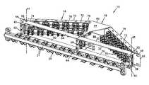
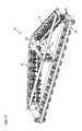
- FIG. 1is a front perspective view of an example patch panel assembly in accordance with the principles of the present disclosure, the assembly including a frame, a pair of pivot modules coupled to the frame in an open angled position, and a first example cable manager;
- FIG. 2is a top view the patch panel assembly of FIG. 1 with the pivot modules arranged in the angled position;
- FIG. 3is a rear perspective view of the patch panel assembly of FIG. 1 with the pivot modules arranged in the angled position;
- FIG. 4is a front perspective view of the patch panel assembly of FIG. 1 with the pivot modules arranged in a closed position;
- FIG. 5is a rear perspective view of the patch panel assembly of FIG. 1 with the pivot modules arranged in the closed position;
- FIG. 6is a front perspective view of the patch panel assembly of FIG. 1 with a second example cable manager
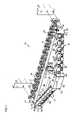
- FIG. 7is a front perspective view of the left side pivot module shown in FIG. 1 ;
- FIG. 8if a front perspective view of the pivot module shown in FIG. 7 with some of the cover members removed;
- FIG. 9is a rear perspective view of the pivot module shown in FIG. 7 ;
- FIG. 10is a rear perspective view of the pivot module shown in FIG. 7 with some of the jack modules removed;
- FIG. 11is a front perspective view of one of the jack modules shown in FIG. 1 ;
- FIG. 12is an exploded perspective view of the jack module shown in FIG. 11 ;
- FIG. 13is a side view illustrating the substrate and electrical contacts of the jack module shown in FIG. 11 ;
- FIG. 14is another side view of the substrate and electrical contacts shown in FIG. 13 ;
- FIG. 15is a front view of the substrate and electrical contacts shown in FIG. 13 ;
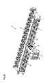
- FIG. 16is a front perspective view of another example patch panel assembly in accordance with the principles of the present disclosure, the assembly including a frame, a pair of pivot modules coupled to the frame in a first open angled position, a first example cable manager, and a nose piece;
- FIG. 17is a rear perspective view of the patch panel assembly of FIG. 16 with the pivot modules arranged in the angled position;
- FIG. 18is a rear perspective view of the patch panel assembly of FIG. 1 with the pivot modules arranged in a second open angled position and the nose piece removed;
- FIG. 19is a front perspective view of the patch panel assembly shown in FIG. 18 ;
- FIG. 20is a rear perspective view of the patch panel assembly of FIG. 16 with the pivot modules arranged in a closed position;
- FIG. 21is a front perspective view of the patch panel assembly of FIG. 1 with the pivot modules arranged in the closed position;
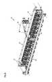
- FIG. 22is a front perspective view of the left side pivot module shown in FIG. 16 ;
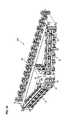
- FIG. 23is a front perspective view of the left side pivot module shown in FIG. 22 with a pair of designator strips and a cover member removed;
- FIG. 24is a rear perspective view of the left side pivot module shown in FIG. 16 .
- the present disclosurerelates to telecommunications patch panels, and more particularly relates to patch panel assemblies that include connector modules that are pivotally connected to a frame of the assembly.
- the connector modulesinclude jack ports on one side and wire termination locations on an opposite side.
- the connector modulesare pivotally coupled at opposite ends of the frame.
- the connector modulescan pivot from a closed position wherein the modules are aligned parallel with the frame, and an angled position wherein the modules are locked in an angled position non-parallel with the frame. In the angled position, the modules provide a shaped structure that facilitates access to the jacks and reduces bend angles for cables coupled to the jacks.
- FIGS. 1-5an embodiment of a patch panel assembly 10 is shown for use in connecting telecommunications equipment.
- Patch panel assembly 10is especially useful to cross-connect equipment through one or more patch panel assemblies 10 or other panels.
- Patch panel assembly 10mounts to a rack (e.g., a portion of a rack 22 shown in FIG. 1 ) of conventional construction.
- the patch panel assembly 10includes a frame 12 , first and second pivot modules 14 , 16 pivotally mounted to the frame 12 , a central support 18 , and a cable manager 20 .
- the pivot modules 14 , 16are mounted to the frame 12 in such a way that they pivot between a closed position (see FIGS. 4 and 5 ) and an open or angled position (see FIGS. 1-3 ).
- the central support 18supports the pivot modules 14 , 16 in the closed and open positions.
- the frame 12includes front and rear planes or faces 30 , 32 , top and bottom sides 34 , 36 , and first and second ends 38 , 40 .
- a pair of brackets 42 , 44extend from first and second ends 38 , 40 .
- the brackets 42 , 44include through holes 46 for purposes of mounting the frame to a rack (e.g., partial rack 22 shown in FIG. 1 ).
- the frame 12defines first and second openings 48 , 50 on opposite sides of the support 18 sized to receive portions of the first and second pivot modules 14 , 16 .
- the frame 12also includes apertures 52 , 54 at opposite ends 38 , 40 through which pivot fasteners (e.g., screws) extend for pivotally mounting the pivot modules 14 , 16 to the frame 12 .
- pivot modules 14 , 16When the pivot modules 14 , 16 are arranged in the closed position (see FIGS. 4 and 5 ) the pivot modules extend in a direction generally parallel with the front and rear faces 30 , 32 and the brackets 42 , 44 .
- the pivot module 14pivots about a pivot axis A 1 (see FIGS. 1 and 3 ) that passes through aperture 52 .
- the pivot module 16pivots about a pivot axis A 2 that passes through aperture 54 .
- a pair of stiffener supports 60 , 62are positioned at opposite ends 38 , 40 of the frame 12 between the top and bottom sides 34 , 36 .
- a cam stiffener support 64is positioned between the top and bottom sides 34 , 36 at a central location between ends 38 , 40 .
- the support 64includes locking cams 56 a for securing the pivot modules 14 , 16 in either the open or closed position.
- the first and second pivot modules 14 , 16each include front and rear planes or faces 70 , 72 , first and second ends 74 , 76 , a plurality of connector jack modules 78 positioned within rows of module openings 77 , and an aperture 82 through which a pivot fastener extends for mounting the modules 14 , 16 at the first end 74 .
- the pivot modules 14 , 16also include an aperture or indent 84 at a front edge at the second end 76 , and an aperture or indent 86 positioned along an end surface at the second end 76 .
- the apertures 84 , 86are used to lock the pivot modules in the open position.
- the pivot modules 14 , 16have a height H and a length L as shown in FIG. 8 .
- the connector jack modules 78each include a front port for receiving a plug and a plurality of rear insulation displacement connectors as described in further detail below related to FIGS. 11-15 .
- the connector jacks modules 78are aligned in two rows (shown stacked above and below each other in the FIGS) with individual jack modules being spaced apart from each other.
- the connector jack modules 78are secured in the module openings 77 with a snap fit connection.
- a plurality of removable covers 80are interspaced between the connector jack modules 78 .
- the covers 80can include a clear material that provides viewing through the covers 80 .
- Designation labelingcan be mounted behind the covers 80 .
- FIGS. 7-9provide a close-up view of the pivot module 14 .
- the upper row of connector jack modules 78is offset in a forward direction from the lower row of connector jack modules 78 . Further, connector jack modules on the upper row are offset laterally from the connector jack modules in the lower row (i.e., the jack modules in upper and lower rows are not aligned vertically) as shown in FIG. 1 .
- the pivot moduleshave a different arrangement of connector jack modules.
- the rows of connector jack modules and corresponding wire termination memberscan be arranged in a single vertical plane rather than the offset orientation shown in the figures.
- the connector jack modulesare positioned directly adjacent to each other rather than being spaced apart.
- the central support 18includes front and rear ends 90 , 92 , top and bottom spaced apart walls 94 , 96 , a stiffener post 98 positioned at the rear end 92 between the walls 94 , 96 , and stiffener posts 99 at the front end 90 between walls 94 , 96 (see FIG. 5 ).
- the stiffener posts 98 , 99provide structure that spaces apart the walls 94 , 96 and secures the walls 94 , 96 together.
- the support 18further includes cams 56 b used to secure the pivot modules in the open or angled position, and side bevels 102 , 104 that act as stops for limiting the forward pivotal movement of the pivot modules 14 , 16 .
- the central support 18acts as a guide track for movement of the otherwise unsupported second ends 76 of the pivot modules 14 , 16 between the closed and open positions.
- the top and bottom sides 94 , 96provide a track structure wherein the second ends 76 of the pivot modules 14 , 16 move through a rotation path between the closed position (see FIG. 4 ) and open position (see FIG. 1 ).
- the side bevels 102 , 104 and cams 56 bare used to secure the pivot modules 14 , 16 in the open position.
- the locking cams 56 a , 56 bcan be mounted to the stiffener posts 64 , 99 . Screw heads allow the cams 56 a , 56 b to be turned from the front of the panel assembly 10 .
- Cams 56 a , 56 bfit within the indents 84 , 86 to secure the pivot modules in the open or closed positions.
- Another example latching system configured to releaseably retain a pivoting telecommunications module in placeis disclosed in U.S. Published Patent Application No. 2005/0191901, which application is incorporated herein by reference. It will be appreciated that any other type of latching arrangement could also be used.
- the stiffener posts 60 , 62 , 64 , 98 , 99can be separate pieces that are connected to the frame 12 and support 18 , or can be integrally formed as part of the frame 12 and support 18 . Further, the locking cams 56 a , 56 b can be integrally formed with the frame 12 and support 18 as separate pieces from the stiffener posts 60 , 62 , 64 , 98 , 99 .
- the open positionis attained by rotating the pivot module 14 from the closed position (shown in FIGS. 4 and 5 ) in a clockwise direction and rotating the pivot module 16 in a counterclockwise direction (as seen from the top view of FIG. 2 ).
- the pivot modules 14 , 16rotate in the counterclockwise and clockwise directions, respectively.
- An angle of rotation a (see FIG. 2 ) of the pivot modules 14 , 16is measured from the front face 30 of the frame 12 and the front face 70 of the pivot modules.
- the rotation angle ⁇ between the close position of FIG. 4 and the open position of FIG. 1is about 10° to about 60°, and more preferably about 30° to about 35°.
- the back side of the pivot modules 14 , 16abuts against the front face of the frame 12 , which orients the pivot modules 14 , 16 parallel with the longitudinal dimension of the frame 12 .
- front side of the pivot modules 14 , 15abut against the bevels 102 , 104 .
- the cams 56 b on the stiffeners 99are used to lock the pivot modules 14 , 16 in the open position and the cams 56 a on the stiffener 64 are used to lock the pivot modules 14 , 16 in the closed position.
- the panel assembly 10can include additional locking cams 56 a , 56 b positioned along the module support 18 to hold the pivot modules at different angled positions.
- the panel assembly 10can be configured to permit the pivot modules 14 , 16 to rotate beyond the open angled position shown in FIG. 1 .
- the module support 18can have a greater length (measured from the front end 90 to the rear end 92 at the frame 12 ) and width (measured between outer edges of side bevels 102 , 104 ) that could support the pivot modules in rotated positions with an angle ⁇ greater than shown in FIG. 1 .
- the panel assemblyis configured to permit the pivot modules 14 , 16 to pivot away from the module support as shown in FIGS. 18 and 19 to an angle ⁇ of, for example, greater than 60°, and preferably about 80° to about 100°.
- the side bevels 102 , 104may need to be removed or modified in order to permit such rotation.
- the capability to rotate the pivot modules 14 , 16 into a range of different angled positionscan provide improved operability for a user connecting plugs, connectors, wires, etc. to the pivot modules 14 , 16 .
- each pivot module 14 , 16When operating the patch panel assembly 10 during coupling of wires and cables to the pivot modules 14 , 16 , each pivot module 14 , 16 is first positioned in the closed orientation (shown in FIGS. 4 and 5 ) wherein a front face of the pivot module is aligned generally parallel with a front face or surface 32 of the frame 12 . Because the frame 12 is configured as a linear member between opposite ends 38 , 40 that is aligned generally parallel with the brackets 42 , 44 , the pivot modules 14 , 16 are also aligned generally parallel with each other when they are each in the closed position. In the closed position, it can be easier to use a termination tool (not shown) to mount wires (not shown) to each of the jack modules 78 .
- the locking cams 56 a , 56 bare released to allow rotation of the pivot modules 14 , 16 into an angled position relative to the frame 12 .
- the pivot modules 14 , 16rotate until the second ends 76 engage the locking cams 56 a , 56 b of the stiffener 99 at the front end 90 of the central support 18 .
- Fasteners 100can be used to secure the pivot modules 14 , 16 in the angled position as shown in FIGS. 1-3 .
- the pivot modules 14 , 16rotate about a pivot fastener inserted into aperture 82 , which are aligned parallel with apertures 52 , 54 and stiffeners 60 , 62 of the frame 12 . Similar fasteners are also preferably provided at the bottom of the frame 12 .
- the axis of rotation of the pivot modules 14 , 16 via the pivot fastener extending through the aperture 82is aligned generally parallel with the front face 30 of the frame and face 70 of the pivot modules.
- the fastener extending through apertures 52 , 54 , 82can be, for example, a screw that is inserted through the opening 82 into the openings 52 , 54 defined in the plastic body of stiffeners 60 , 62 .
- the screwcan provide both fastening function to secure the pivot modules 14 , 16 to the frame 12 while permitting the pivot modules 14 , 16 to pivot relative to the frame 12 .
- the jack modules 78include a dielectric housing 122 having a front piece 124 and a rear piece 126 .
- the front and rear pieces 124 , 126can be interconnected by a snap fit connection.
- the front piece 124defines a front port 128 sized and shaped to receive a conventional telecommunications plug (e.g., an RJ style plug such as an RJ 45 plug).
- the rear piece 126defines an insulation displacement connector interface and includes a plurality of towers 130 adapted to house insulation displacement connector blades/contacts.
- the jack modules 78further include a circuit board 132 that mounts between the front and rear pieces 124 , 126 of the housing 122 .
- a plurality of contact springs CS 1 -CS 8are terminated to a front side of the circuit board 132 .
- a plurality of insulation displacement connector blades IDC 1 -IDC 8are terminated to a back side of the circuit board 132 .
- the contact springs CS 1 -CS 8extend into the front port 128 and are adapted to be electrically connected to corresponding contacts provided on a plug when the plug is inserted into the front port 128 .
- the insulation displacement connector blades IDC 1 -IDC 8fit within the towers 130 of the rear piece 126 of the housing 122 .
- the circuit board 132has tracks T 1 -T 8 (e.g., tracings, see FIGS. 14-17 ) that respectively electrically connect the contact springs CS 1 -CS 8 to the insulation displacement connector blades IDC 1 -IDC 8 .
- wiresare electrically connected to the contact springs CS 1 -CS 8 by inserting the wires between pairs of the insulation displacement connector blades IDC 1 -IDC 8 .
- the wiresare inserted between pairs of the insulation displacement connector blades IDC 1 -IDC 8 , the blades cut through the insulation of the wires and make electrical contact with the center conductors of the wires.
- the insulation displacement connector blades IDC 1 -IDC 8which are electrically connected to the contact springs CS 1 -CS 8 by the tracks on the circuit board, provide an efficient means for electrically connecting a twisted pair of wires to the contact springs CS 1 -CS 8 of the jack modules 78 .
- the contact springs CS 1 -CS 8are shown more clearly in FIGS. 13-15 .
- the relative positioning, shape and curvature of the contact springs CS 1 -CS 8is preferably adapted to provide some initial crosstalk compensation at the jack module 78 .
- Each jack modules 78includes a resilient latch tab 134 (see FIG. 11 ) on a top side and a pair of latch posts 136 (see FIG. 12 ) on a bottom side.
- the latch tab 134is received into a latch tab opening 88 (see FIG. 10 ) at a top side of the module openings 77 in the pivot modules 14 , 16
- the latch posts 136are received into latch post openings 89 (see FIG. 10 ) at a bottom side of each of the module openings 77 of the pivot modules 14 , 16 .
- the jack modules 78is snap fit into the module opening 77 by first inserting the latch posts 136 into the openings 89 from the back side of the pivot module 14 , 16 , and then rotating the jack module until the latch tab 134 locks within the opening 88 .
- the jack modulescan be secured to the pivot modules 14 , 16 with other connection means such as fasteners and adhesives.
- the jack modules 78are connected to the pivot modules 14 , 16 with a releasable connection.
- the panel assembly 200includes many of the same or similar features as shown with reference to panel assembly 10 described above with reference to FIGS. 1-15 .
- the panel assemblyadditionally includes a removable nose piece 93 secured to a front surface 91 of the module support 18 .
- the nose piece 93is secured to the module support 18 by fasteners such as, for example, manual pop rivets 95 that extend through the nose piece 93 into the front surface 91 .
- the nose piece 93has features that replace the function of side bevels 102 , 104 shown in FIG. 1 .
- the pop rivets 95By pulling out the pop rivets 95 , the nose piece 93 can be removed from the module support 18 .
- the pivot modules 14 , 16can be pivoted past the nose piece 93 and module support 19 to an open position as shown in FIGS. 18 and 19 .
- the pivot modules 14 , 16 of panel assembly 200include jack modules 78 that are staggered from left to right relative to one another as in panel assembly 10 . However, the upper and lower rows of jack modules 78 on each pivot module 14 , 16 are not staggered from front to back (see FIG. 21 ) as are the rows ofjack modules 78 in panel assembly 10 . Additionally, as also shown in FIGS. 21-23 , each of the pivot modules 14 , 16 has clear windows 81 for holding icons such as data/voice icons (not shown) or other identification material. The windows 81 can be covered with a cover member 80 (see FIG. 23 ) or other structure that prohibits viewing the windows 81 .
- the pivot modules 14 , 16also include designation strips 110 over which clear slide windows can be mounted. The designation strips 110 allow designation information to be provided adjacent the ports.
- the pivot modules 14 , 16 of panel assembly 200include a shield member 112 between the upper and lower rows of jack modules (see FIG. 24 ). It will be appreciated that the shield member 112 can define the openings 89 for receiving the posts/pegs provided at the underside of the jack modules.
- the shieldcan comprise materials adapted for blocking transmissions that may cause cross-talk between the jack modules. Some example materials include metallic or carbon filled materials.
- the latching arrangement for securing the pivot modules 14 , 16 in place in panel assembly 200works in a similar manner as described above with reference to panel assembly 10 .
- the pivot modules 14 , 16include recesses 84 , 86 on the end of the pivot modules 14 , 16 for receiving the locking cams 56 a , 56 b of the stiffening members 64 , 99 to hold the pivot module in either the closed position (see FIG. 21 ) or the open angled position (see FIG. 19 ).
- the pivot modules 14 , 16further include, with reference to FIG. 23 , recesses 114 , 116 at top and bottom sides at the end of the pivot modules 14 , 16 .
- the recesses 114 , 116allow the pivot modules 114 , 116 to better slide between the upper and lower walls 94 , 96 of the module support 18 when rotating between the open ( FIG. 19 ) and closed positions ( FIG. 21 ).
- a telecommunications device in accordance with inventive principles disclosed hereinincludes a frame and a plurality of pivot modules mounted to the frame.
- the framehas a length that extends from a left end to a right end of the frame.
- the frameincludes a left mounting bracket positioned at the left end of the frame and a right mounting bracket positioned at the right end of the frame.
- the framealso includes upper and lower portions that extend along the length of the frame.
- the pivot modulesare mounted between the upper and lower portions of the frame and between the left and right ends of the frame.
- Each of the pivot modulesinclude a front side at which a plurality of front connectors are located, and a rear side at which a plurality of rear connectors are located.
- the pivot modulesare pivotally movable about generally upright pivot axes that extend between the upper and lower portions of the frame.
- the pivot axesis located adjacent one of the first and second ends of the pivot modules.
- Each pivot modulehas a height that extends between the upper and lower portions of the frame and a length that extends between the left and right ends of the frame.
- the lengths of the pivot modulesare longer than the heights, and the lengths of the pivot modules are generally perpendicular relative to the pivot axes.
- the lengths of the pivot modulesextend from first to second ends of the pivot modules.
- the framehas a length that extends from a left end to a right end of the frame.
- the frameincludes a left mounting bracket positioned at the left end of the frame and a right mounting bracket positioned at the right end of the frame.
- the framealso includes upper and lower portions that extend along the length of the frame.
- the central supportprojects forwardly from the frame at a central region located between the left and right ends of the frame.
- the first pivot moduleis mounted to the frame between the left end of the frame and the central support.
- the first pivot moduleincludes a front side at which a plurality of front connectors are located and a rear side at which a plurality of rear connectors are located.
- the first pivot modulehas an outer end positioned adjacent the left mounting bracket and an inner end positioned adjacent the central support.
- the first pivot moduleis pivotally movable relative to the frame about a generally upright first pivot axes located adjacent the outer end of the first pivot module.
- the inner end of the first pivot moduleis supported by the central support.
- the second pivot moduleis mounted to the frame between the right end of the frame and the central support.
- the second pivot moduleincludes a front side at which a plurality of front connectors are located and a rear side at which a plurality of rear connectors are located.
- the second pivot modulehas an outer end positioned adjacent the right mounting bracket and an inner end positioned adjacent the central support.
- the second pivot moduleis pivotally movable relative to the frame about a generally upright second pivot axes located adjacent the outer end of the second pivot module.
- the inner end of the second pivot moduleis supported by the central support.
- the first and second pivot modulesare pivotally movable to an angled position in which the inner ends of the first and second pivot modules are forwardly offset from the frame and the first and second pivot modules define a generally v-shaped configuration.
Landscapes
- Engineering & Computer Science (AREA)
- Computer Networks & Wireless Communication (AREA)
- Connector Housings Or Holding Contact Members (AREA)
- Structure Of Telephone Exchanges (AREA)
- Casings For Electric Apparatus (AREA)
Abstract
Description
Claims (20)
Priority Applications (8)
| Application Number | Priority Date | Filing Date | Title |
|---|---|---|---|
| US11/472,816US7357667B2 (en) | 2006-06-22 | 2006-06-22 | Telecommunications patch |
| RU2009101921/09ARU2009101921A (en) | 2006-06-22 | 2007-06-05 | DEVICE FOR TELECOMMUNICATIONS |
| PCT/US2007/013233WO2007149215A2 (en) | 2006-06-22 | 2007-06-05 | Telecommunications patch |
| EP07795755AEP2030453A2 (en) | 2006-06-22 | 2007-06-05 | Telecommunications patch |
| TW096122561ATW200814434A (en) | 2006-06-22 | 2007-06-22 | Telecommunications patch |
| US12/103,393US7607938B2 (en) | 2006-06-22 | 2008-04-15 | Telecommunications patch |
| ZA200900442AZA200900442B (en) | 2006-06-22 | 2009-01-20 | Telecommunications patch |
| US12/563,279US7811122B2 (en) | 2006-06-22 | 2009-09-21 | Telecommunications patch |
Applications Claiming Priority (1)
| Application Number | Priority Date | Filing Date | Title |
|---|---|---|---|
| US11/472,816US7357667B2 (en) | 2006-06-22 | 2006-06-22 | Telecommunications patch |
Related Child Applications (1)
| Application Number | Title | Priority Date | Filing Date |
|---|---|---|---|
| US12/103,393ContinuationUS7607938B2 (en) | 2006-06-22 | 2008-04-15 | Telecommunications patch |
Publications (2)
| Publication Number | Publication Date |
|---|---|
| US20070298652A1 US20070298652A1 (en) | 2007-12-27 |
| US7357667B2true US7357667B2 (en) | 2008-04-15 |
Family
ID=38823508
Family Applications (3)
| Application Number | Title | Priority Date | Filing Date |
|---|---|---|---|
| US11/472,816Expired - Fee RelatedUS7357667B2 (en) | 2006-06-22 | 2006-06-22 | Telecommunications patch |
| US12/103,393Active2026-06-24US7607938B2 (en) | 2006-06-22 | 2008-04-15 | Telecommunications patch |
| US12/563,279Expired - Fee RelatedUS7811122B2 (en) | 2006-06-22 | 2009-09-21 | Telecommunications patch |
Family Applications After (2)
| Application Number | Title | Priority Date | Filing Date |
|---|---|---|---|
| US12/103,393Active2026-06-24US7607938B2 (en) | 2006-06-22 | 2008-04-15 | Telecommunications patch |
| US12/563,279Expired - Fee RelatedUS7811122B2 (en) | 2006-06-22 | 2009-09-21 | Telecommunications patch |
Country Status (6)
| Country | Link |
|---|---|
| US (3) | US7357667B2 (en) |
| EP (1) | EP2030453A2 (en) |
| RU (1) | RU2009101921A (en) |
| TW (1) | TW200814434A (en) |
| WO (1) | WO2007149215A2 (en) |
| ZA (1) | ZA200900442B (en) |
Cited By (27)
| Publication number | Priority date | Publication date | Assignee | Title |
|---|---|---|---|---|
| US20080115956A1 (en)* | 2006-11-20 | 2008-05-22 | Panduit Corp. | Angled Patch Panel Cover Plate |
| US20080175550A1 (en)* | 2007-01-19 | 2008-07-24 | Hutch Coburn | Fiber optic adapter cassette and panel |
| US20080207048A1 (en)* | 2006-02-10 | 2008-08-28 | Panduit Corp. | Angled Patch Panel with Pitched Connector Alignment |
| US20090068881A1 (en)* | 2007-09-06 | 2009-03-12 | Adc Gmbh | Telecommunication patch panel |
| US20090163043A1 (en)* | 2007-12-21 | 2009-06-25 | Yannick Demers | Patch panel with angled module |
| US20100081319A1 (en)* | 2006-06-22 | 2010-04-01 | Adc Telecommunications, Inc. | Telecommunications Patch |
| US20100158465A1 (en)* | 2008-12-09 | 2010-06-24 | Mark Smrha | Fiber optic adapter plate and cassette |
| US20100248535A1 (en)* | 2009-03-26 | 2010-09-30 | Cisco Technology, Inc. | Reconfigurable Patch Panel |
| US20110217867A1 (en)* | 2009-03-03 | 2011-09-08 | Adc Gmbh | Consolidation point enclosure |
| US20120227262A1 (en)* | 2011-03-10 | 2012-09-13 | Gross Charles M | Method and apparatus for mounting a cable connector onto a panel |
| US8600208B2 (en) | 2010-08-24 | 2013-12-03 | Adc Telecommunications, Inc. | Fiber optic telecommunications module |
| US9146374B2 (en) | 2012-09-28 | 2015-09-29 | Adc Telecommunications, Inc. | Rapid deployment packaging for optical fiber |
| US20150370028A1 (en)* | 2010-06-02 | 2015-12-24 | Tyco Electronics Corporation | Switch rack system |
| US9223094B2 (en) | 2012-10-05 | 2015-12-29 | Tyco Electronics Nederland Bv | Flexible optical circuit, cassettes, and methods |
| US9332669B1 (en)* | 2015-02-13 | 2016-05-03 | Martas Precision Slide Co., Ltd. | Cable management arm of server rack |
| US9348104B2 (en) | 2012-12-11 | 2016-05-24 | CommScope Connectivity Belgium BVBA | Universal cable management system for telecommunications rack |
| US9435975B2 (en) | 2013-03-15 | 2016-09-06 | Commscope Technologies Llc | Modular high density telecommunications frame and chassis system |
| US9535229B2 (en) | 2011-10-07 | 2017-01-03 | Commscope Technologies Llc | Fiber optic cassette, system, and method |
| US9885845B2 (en)* | 2015-01-15 | 2018-02-06 | Commscope, Inc. Of North Carolina | Module and assembly for fiber optic interconnections |
| US9910236B2 (en) | 2008-08-29 | 2018-03-06 | Corning Optical Communications LLC | High density and bandwidth fiber optic apparatuses and related equipment and methods |
| US10094996B2 (en) | 2008-08-29 | 2018-10-09 | Corning Optical Communications, Llc | Independently translatable modules and fiber optic equipment trays in fiber optic equipment |
| US20190008075A1 (en)* | 2017-06-30 | 2019-01-03 | Quanta Computer Inc. | Arc shape front panel |
| US11294135B2 (en) | 2008-08-29 | 2022-04-05 | Corning Optical Communications LLC | High density and bandwidth fiber optic apparatuses and related equipment and methods |
| US11372165B2 (en) | 2011-09-12 | 2022-06-28 | Commscope Technologies Llc | Flexible lensed optical interconnect device for signal distribution |
| US11409068B2 (en) | 2017-10-02 | 2022-08-09 | Commscope Technologies Llc | Fiber optic circuit and preparation method |
| US11592628B2 (en) | 2012-09-28 | 2023-02-28 | Commscope Technologies Llc | Fiber optic cassette |
| US12339511B2 (en) | 2020-03-31 | 2025-06-24 | Commscope Technologies Llc | Fiber optic cable management systems and methods |
Families Citing this family (67)
| Publication number | Priority date | Publication date | Assignee | Title |
|---|---|---|---|---|
| DE102005038540B3 (en)* | 2005-08-16 | 2007-01-11 | Adc Gmbh | Assembly fixture e.g. for line and plug connection elements, has front panel which has carrying structure with lateral carrying elements as well as screen with several openings for female connectors |
| EP2057849A2 (en)* | 2006-08-22 | 2009-05-13 | Turk Telekomunikasyon A.S. | Double-sided data termination block |
| US8061534B2 (en)* | 2006-09-08 | 2011-11-22 | Leviton Manufacturing Co., Inc. | Equipment rack panel system and method |
| USD632268S1 (en) | 2007-09-07 | 2011-02-08 | Leviton Manufacturing Co., Inc. | Equipment rack panel |
| US8119915B2 (en)* | 2007-10-05 | 2012-02-21 | Leviton Manufacturing Co., Inc. | Cable management patch panel system with vertical ducting |
| US7856166B2 (en) | 2008-09-02 | 2010-12-21 | Corning Cable Systems Llc | High-density patch-panel assemblies for optical fiber telecommunications |
| US7898787B2 (en)* | 2008-10-09 | 2011-03-01 | Adc Telecommunications, Inc. | Power panel with angled connectors |
| EP2207362A1 (en)* | 2009-01-09 | 2010-07-14 | 3M Innovative Properties Company | Telecommunication assembly |
| EP2221932B1 (en) | 2009-02-24 | 2011-11-16 | CCS Technology Inc. | Holding device for a cable or an assembly for use with a cable |
| US8286325B2 (en) | 2009-03-31 | 2012-10-16 | Corning Cable Systems Llc | Hinged fiber optic module housing and module and methods of manufacture and assembly |
| US8699838B2 (en) | 2009-05-14 | 2014-04-15 | Ccs Technology, Inc. | Fiber optic furcation module |
| US7896692B2 (en)* | 2009-05-15 | 2011-03-01 | Leviton Manufacturing Co., Inc. | Method of improving isolation between circuits on a printed circuit board |
| US8538226B2 (en) | 2009-05-21 | 2013-09-17 | Corning Cable Systems Llc | Fiber optic equipment guides and rails configured with stopping position(s), and related equipment and methods |
| US9075216B2 (en) | 2009-05-21 | 2015-07-07 | Corning Cable Systems Llc | Fiber optic housings configured to accommodate fiber optic modules/cassettes and fiber optic panels, and related components and methods |
| WO2010148325A1 (en) | 2009-06-19 | 2010-12-23 | Corning Cable Systems Llc | High fiber optic cable packing density apparatus |
| US8712206B2 (en) | 2009-06-19 | 2014-04-29 | Corning Cable Systems Llc | High-density fiber optic modules and module housings and related equipment |
| US20110045691A1 (en)* | 2009-08-24 | 2011-02-24 | Hsing Chau Industrial Co., Ltd. | Easily installable network wiring device |
| WO2011047288A1 (en) | 2009-10-16 | 2011-04-21 | Adc Telecommunications, Inc. | Managed connectivity in fiber optic systems and methods thereof |
| US8625950B2 (en) | 2009-12-18 | 2014-01-07 | Corning Cable Systems Llc | Rotary locking apparatus for fiber optic equipment trays and related methods |
| US8992099B2 (en) | 2010-02-04 | 2015-03-31 | Corning Cable Systems Llc | Optical interface cards, assemblies, and related methods, suited for installation and use in antenna system equipment |
| US8913866B2 (en) | 2010-03-26 | 2014-12-16 | Corning Cable Systems Llc | Movable adapter panel |
| CA2796221C (en) | 2010-04-16 | 2018-02-13 | Ccs Technology, Inc. | Sealing and strain relief device for data cables |
| EP2381284B1 (en) | 2010-04-23 | 2014-12-31 | CCS Technology Inc. | Under floor fiber optic distribution device |
| US9519118B2 (en) | 2010-04-30 | 2016-12-13 | Corning Optical Communications LLC | Removable fiber management sections for fiber optic housings, and related components and methods |
| US8660397B2 (en) | 2010-04-30 | 2014-02-25 | Corning Cable Systems Llc | Multi-layer module |
| US9075217B2 (en) | 2010-04-30 | 2015-07-07 | Corning Cable Systems Llc | Apparatuses and related components and methods for expanding capacity of fiber optic housings |
| US9720195B2 (en) | 2010-04-30 | 2017-08-01 | Corning Optical Communications LLC | Apparatuses and related components and methods for attachment and release of fiber optic housings to and from an equipment rack |
| US8705926B2 (en) | 2010-04-30 | 2014-04-22 | Corning Optical Communications LLC | Fiber optic housings having a removable top, and related components and methods |
| US9632270B2 (en) | 2010-04-30 | 2017-04-25 | Corning Optical Communications LLC | Fiber optic housings configured for tool-less assembly, and related components and methods |
| US8879881B2 (en) | 2010-04-30 | 2014-11-04 | Corning Cable Systems Llc | Rotatable routing guide and assembly |
| US8718436B2 (en) | 2010-08-30 | 2014-05-06 | Corning Cable Systems Llc | Methods, apparatuses for providing secure fiber optic connections |
| US9279951B2 (en) | 2010-10-27 | 2016-03-08 | Corning Cable Systems Llc | Fiber optic module for limited space applications having a partially sealed module sub-assembly |
| US9116324B2 (en) | 2010-10-29 | 2015-08-25 | Corning Cable Systems Llc | Stacked fiber optic modules and fiber optic equipment configured to support stacked fiber optic modules |
| US8662760B2 (en) | 2010-10-29 | 2014-03-04 | Corning Cable Systems Llc | Fiber optic connector employing optical fiber guide member |
| CA2819235C (en) | 2010-11-30 | 2018-01-16 | Corning Cable Systems Llc | Fiber device holder and strain relief device |
| WO2012106510A2 (en) | 2011-02-02 | 2012-08-09 | Corning Cable Systems Llc | Dense fiber optic connector assemblies and related connectors and cables suitable for establishing optical connections for optical backplanes in equipment racks |
| US8834199B2 (en)* | 2011-04-11 | 2014-09-16 | Hsing Chau Industrial Co., Ltd. | Tilted module for assembling network distribution device |
| US20120273627A1 (en)* | 2011-04-26 | 2012-11-01 | Panduit Corp. | Horizontal Cable Manager |
| US9008485B2 (en) | 2011-05-09 | 2015-04-14 | Corning Cable Systems Llc | Attachment mechanisms employed to attach a rear housing section to a fiber optic housing, and related assemblies and methods |
| AU2012275598A1 (en) | 2011-06-30 | 2014-01-16 | Corning Optical Communications LLC | Fiber optic equipment assemblies employing non-U-width-sized housings and related methods |
| US8953924B2 (en) | 2011-09-02 | 2015-02-10 | Corning Cable Systems Llc | Removable strain relief brackets for securing fiber optic cables and/or optical fibers to fiber optic equipment, and related assemblies and methods |
| US9038832B2 (en) | 2011-11-30 | 2015-05-26 | Corning Cable Systems Llc | Adapter panel support assembly |
| US9461428B2 (en)* | 2012-03-08 | 2016-10-04 | Nvidia Corporation | Low-cost offset stacked power connector |
| CN104247181B (en)* | 2012-04-06 | 2017-02-22 | 雷比诺有限公司 | Panels and electrical switchgear control panels including panels |
| US9420715B2 (en)* | 2012-06-07 | 2016-08-16 | Intal Tech Ltd. | Electrononic equipment building blocks for rack mounting |
| US9521766B2 (en) | 2012-06-27 | 2016-12-13 | CommScope Connectivity Belgium BVBA | High density telecommunications systems with cable management and heat dissipation features |
| US9250409B2 (en) | 2012-07-02 | 2016-02-02 | Corning Cable Systems Llc | Fiber-optic-module trays and drawers for fiber-optic equipment |
| US9042702B2 (en) | 2012-09-18 | 2015-05-26 | Corning Cable Systems Llc | Platforms and systems for fiber optic cable attachment |
| US20140094057A1 (en)* | 2012-10-01 | 2014-04-03 | Panduit Corp. | Modular Patch Panel System |
| ES2551077T3 (en) | 2012-10-26 | 2015-11-16 | Ccs Technology, Inc. | Fiber optic management unit and fiber optic distribution device |
| CN105074525A (en) | 2013-01-29 | 2015-11-18 | 泰科电子瑞侃有限公司 | Fiber Distribution System |
| US9423570B2 (en) | 2013-02-05 | 2016-08-23 | Commscope Technologies Llc | Optical assemblies with managed connectivity |
| US8985862B2 (en) | 2013-02-28 | 2015-03-24 | Corning Cable Systems Llc | High-density multi-fiber adapter housings |
| EP2989496B1 (en)* | 2013-04-24 | 2019-06-12 | CommScope Connectivity Belgium BVBA | Universal mounting mechanism for mounting a telecommunications chassis to a telecommunications fixture |
| CN105359549B (en)* | 2013-04-30 | 2018-12-25 | 泰科电子安普西班牙公司 | Patch panel system and for being fixed to jack module thereon |
| US9411117B1 (en)* | 2015-07-09 | 2016-08-09 | Hubbell Incorporated | Cable management device |
| US9888603B1 (en)* | 2016-02-29 | 2018-02-06 | EMC IP Holding Co. LLC | Slider arm assembly for cable carrier |
| EP3698552A4 (en) | 2017-11-20 | 2020-11-18 | Corning Research & Development Corporation | OPTICAL CONNECTION ARRANGEMENTS AND ASSOCIATED SYSTEMS FOR LARGE AREA SPINE AND LEAF TOPOLOGIES |
| WO2019099771A1 (en)* | 2017-11-20 | 2019-05-23 | Corning Research & Development Corporation | Adjustable optical interconnect module for large-scale spine and leaf topologies |
| US10591692B2 (en)* | 2017-12-27 | 2020-03-17 | Afl Ig Llc | Optical distribution frames |
| US10952345B2 (en) | 2018-06-06 | 2021-03-16 | Cisco Technology, Inc. | Adjustable cable management bracket for modular electronic system |
| EP3845044B1 (en) | 2018-08-31 | 2023-02-15 | CommScope Connectivity Belgium BVBA | Frame assemblies for optical fiber distribution elements |
| EP3844546A1 (en) | 2018-08-31 | 2021-07-07 | CommScope Connectivity Belgium BVBA | Frame assemblies for optical fiber distribution elements |
| PL3844973T3 (en) | 2018-08-31 | 2025-03-03 | CommScope Connectivity Belgium BVBA | Frame assemblies for optical fiber distribution elements |
| EP3844547A1 (en) | 2018-08-31 | 2021-07-07 | CommScope Connectivity Belgium BVBA | Frame assemblies for optical fiber distribution elements |
| WO2020043914A1 (en) | 2018-08-31 | 2020-03-05 | CommScope Connectivity Belgium BVBA | Frame assemblies for optical fiber distribution elements |
| WO2020084012A1 (en) | 2018-10-23 | 2020-04-30 | CommScope Connectivity Belgium BVBA | Frame assemblies for optical fiber distribution elements |
Citations (80)
| Publication number | Priority date | Publication date | Assignee | Title |
|---|---|---|---|---|
| US1616114A (en) | 1925-03-30 | 1927-02-01 | Western Electric Co | Telephone jack |
| US2317450A (en) | 1942-04-25 | 1943-04-27 | Cook Electric Co | Terminal box |
| US2427349A (en) | 1944-11-16 | 1947-09-16 | Earl S Boynton | Electrical receptacle |
| US3337059A (en) | 1965-10-13 | 1967-08-22 | Hoy David P Le | Disc holder |
| US3611264A (en) | 1968-12-27 | 1971-10-05 | Bell Telephone Labor Inc | Wire connecting blocks |
| US3915541A (en) | 1972-10-18 | 1975-10-28 | Philips Corp | Junction box |
| US3953100A (en) | 1975-04-04 | 1976-04-27 | Liebert Corporation | Infrared lamp holder |
| US3958850A (en) | 1972-04-28 | 1976-05-25 | Bunker Ramo Corporation | Method and apparatus for connecting multi-conductor cables |
| US4085992A (en) | 1974-03-06 | 1978-04-25 | Bunker Ramo Corporation | Method and apparatus for connecting multi-conductor cables |
| USD247965S (en) | 1976-05-10 | 1978-05-23 | Gray Steven M | Telephone answering service console |
| US4131330A (en) | 1976-03-31 | 1978-12-26 | Bunker Ramo Corporation | Mounting device for electrical connectors |
| USD271965S (en) | 1981-03-06 | 1983-12-27 | Hollfelder Thomas A | Telephone terminal block or similar article |
| US4536052A (en) | 1984-02-09 | 1985-08-20 | At&T Information Systems | Modular cross-connect panel |
| US4747020A (en) | 1986-05-16 | 1988-05-24 | Adc Telecommunications, Inc. | Wire distribution apparatus |
| US4815104A (en) | 1988-01-11 | 1989-03-21 | Telect, Inc. | Digital telecommunications network, cross-connect module |
| US4824196A (en)* | 1987-05-26 | 1989-04-25 | Minnesota Mining And Manufacturing Company | Optical fiber distribution panel |
| US4995688A (en) | 1989-07-31 | 1991-02-26 | Adc Telecommunications, Inc. | Optical fiber distribution frame |
| US5000703A (en) | 1989-01-26 | 1991-03-19 | Krone Aktiengesellschaft | Connector bank |
| US5011257A (en) | 1988-06-29 | 1991-04-30 | British Telecommunications Public Limited Company | Optical fiber patch panel |
| US5127082A (en) | 1991-03-22 | 1992-06-30 | The Siemon Company | Fiber optic patch panel |
| US5129842A (en) | 1991-04-08 | 1992-07-14 | Digital Equipment Corporation | Modular patch panel |
| US5139445A (en) | 1990-12-07 | 1992-08-18 | The Siemon Company | Modular test adapter |
| US5178554A (en) | 1990-10-26 | 1993-01-12 | The Siemon Company | Modular jack patching device |
| US5238426A (en) | 1992-06-11 | 1993-08-24 | At&T Bell Laboratories | Universal patch panel for communications use in buildings |
| US5299956A (en) | 1992-03-23 | 1994-04-05 | Superior Modular Products, Inc. | Low cross talk electrical connector system |
| US5302140A (en) | 1993-04-02 | 1994-04-12 | At&T Bell Laboratories | Connector with mounting collar for use in universal patch panel systems |
| US5303519A (en) | 1991-09-16 | 1994-04-19 | E. L. Mustee & Sons, Inc. | Shower stall with molded angle panel |
| US5370553A (en) | 1993-03-12 | 1994-12-06 | At&T Corp. | Adjustable terminations in equipment housing for cables |
| US5370541A (en) | 1993-01-25 | 1994-12-06 | Minnesota Mining And Manufacturing Company | Repositionable termination module |
| US5412751A (en) | 1993-08-31 | 1995-05-02 | The Siemon Company | Retrofittable multimedia patch management system |
| US5415296A (en) | 1993-07-13 | 1995-05-16 | Wright; Robert K. | Display system for use with jewel type compact disc packaging containers, and method of use |
| USD367037S (en) | 1995-01-17 | 1996-02-13 | Woods Industries, Inc. | Electrical outlet unit |
| US5530954A (en) | 1995-01-13 | 1996-06-25 | Telect, Inc. | Telecommunication fiber optic patch panel shelf assembly |
| EP0736937A1 (en) | 1995-04-04 | 1996-10-09 | Atreus Enterprises Limited | Electrical accessory |
| US5575665A (en) | 1995-12-01 | 1996-11-19 | Superior Modular Products Incorporated | Patch panel with hinged tie bar |
| US5591045A (en) | 1995-05-18 | 1997-01-07 | The Whitaker Corporation | Wire connecting system |
| US5639261A (en) | 1994-12-23 | 1997-06-17 | Lucent Technologies Inc. | Modular cross-connect system |
| US5645449A (en) | 1995-02-21 | 1997-07-08 | The Whitaker Corporation | Low profile mixed media information outlet |
| US5659650A (en) | 1995-09-26 | 1997-08-19 | Lucent Technologies Inc. | Hinged faceplate |
| US5674093A (en) | 1996-07-23 | 1997-10-07 | Superior Modular Process Incorporated | Reduced cross talk electrical connector |
| US5676566A (en) | 1994-11-04 | 1997-10-14 | The Siemon Company | Multimedia outlet |
| US5700167A (en) | 1996-09-06 | 1997-12-23 | Lucent Technologies | Connector cross-talk compensation |
| US5721394A (en) | 1996-07-12 | 1998-02-24 | Mulks; Robert | Flush mount multiport connection box |
| US5734776A (en)* | 1996-08-28 | 1998-03-31 | Adc Telecommunications, Inc. | Outside plant cross-connect apparatus |
| US5735714A (en) | 1995-04-06 | 1998-04-07 | Ortronics Inc. | Information management outlet module and assembly providing protection to exposed cabling |
| US5788087A (en) | 1996-03-18 | 1998-08-04 | Ortronics, Inc. | Hinged wire management panel assembly |
| US5836786A (en) | 1996-05-21 | 1998-11-17 | The Whitaker Corporation | Patch panel having snap together construction |
| US5888079A (en) | 1997-10-16 | 1999-03-30 | Eugene A Norden | Telephone service panels |
| US5921402A (en) | 1998-04-27 | 1999-07-13 | Systems Manufacturing Corporation | Cable management track system |
| US5944535A (en) | 1997-02-04 | 1999-08-31 | Hubbell Incorporated | Interface panel system for networks |
| US5945633A (en) | 1996-05-23 | 1999-08-31 | The Siemon Company | Rack mountable cable distribution enclosure having an angled adapter plate bracket |
| US5956449A (en) | 1997-02-26 | 1999-09-21 | Nec Corporation | Structure for mounting an optical circuit |
| US5969294A (en) | 1997-12-31 | 1999-10-19 | Siecor Operations, Llc | Fiber optic connector cabinet with rotatably mounted adapter panels |
| US5984720A (en)* | 1997-10-17 | 1999-11-16 | Hubbell Incorporated | Angled interconnect panel assembly for telecommunications applications |
| US5993251A (en) | 1997-12-22 | 1999-11-30 | Nortel Networks Corporation | Staggered Faceplate |
| US6146192A (en) | 1999-03-31 | 2000-11-14 | Adc Telecommunications, Inc. | Bulkhead connector system including angled adapter |
| US6200159B1 (en) | 1999-10-15 | 2001-03-13 | Jonie Chou | Multi-deck electric outlet assembly |
| US6208796B1 (en) | 1998-07-21 | 2001-03-27 | Adc Telecommunications, Inc. | Fiber optic module |
| US6236795B1 (en) | 1999-06-07 | 2001-05-22 | E. Walter Rodgers | High-density fiber optic cable distribution frame |
| US6240234B1 (en) | 1999-12-01 | 2001-05-29 | Cisco Technology, Inc. | Mechanism for securing cables |
| US6242698B1 (en) | 1998-12-08 | 2001-06-05 | Avaya Technology Corporation | Interchangeable adapter face plates |
| US6259852B1 (en) | 2000-01-05 | 2001-07-10 | Avaya Technology Corp. | Fiber optic pedestal |
| US6293707B1 (en) | 1999-02-19 | 2001-09-25 | Lucent Technologies Inc. | Patch panel with pivoting bracket assembly |
| US6350148B1 (en) | 1999-02-10 | 2002-02-26 | Avaya Technology Corp. | Method and device for detecting the presence of a patch cord connector in a telecommunications patch system |
| US6468112B1 (en) | 1999-01-11 | 2002-10-22 | Adc Telecommunications, Inc. | Vertical cable management system with ribcage structure |
| US6497578B1 (en) | 2001-04-11 | 2002-12-24 | Nortel Networks Limited | Method and apparatus to increase cable connector density in equipment |
| US6522548B1 (en) | 2001-07-27 | 2003-02-18 | Scientific-Atlanta, Inc. | Faceted extended interface module |
| US6537106B1 (en)* | 1998-06-05 | 2003-03-25 | Adc Telecommunications, Inc. | Telecommunications patch panel with angled connector modules |
| US6565260B2 (en) | 2001-10-19 | 2003-05-20 | Axe, Inc. | High-connector density interface plate |
| US6600106B2 (en) | 2001-07-11 | 2003-07-29 | Adc Telecommunications, Inc. | Cable management bar and patch panel |
| US6614978B1 (en) | 2000-06-02 | 2003-09-02 | Panduit Corp. | Slack cable management system |
| US6692284B1 (en) | 1999-02-26 | 2004-02-17 | Nnb Electronic Technology Pte. Ltd. | Electrical socket and plug |
| US6711339B2 (en) | 2002-05-31 | 2004-03-23 | Adc Telecommunications, Inc. | Fiber management module with cable storage |
| US20040209515A1 (en) | 2003-04-03 | 2004-10-21 | Caveney Jack E. | High density patch panel |
| US6866541B2 (en) | 2001-07-26 | 2005-03-15 | Panduit Corp. | Angled patch panel with cable support bar for network cable racks |
| US6902429B1 (en) | 2004-07-29 | 2005-06-07 | Frederick A. Brooks | Multiple electrical outlet device |
| US20050142910A1 (en) | 2003-12-30 | 2005-06-30 | Levesque Stewart A. | Angled patch panel assembly |
| US6916213B2 (en) | 2000-12-01 | 2005-07-12 | Abb Oy | Connection base |
| US20050233647A1 (en) | 2004-04-14 | 2005-10-20 | Sam Denovich | Non-orthogonal cable management system |
| US20050233635A1 (en) | 2004-04-14 | 2005-10-20 | Sam Denovich | Patch panel system |
Family Cites Families (25)
| Publication number | Priority date | Publication date | Assignee | Title |
|---|---|---|---|---|
| US142932A (en)* | 1873-09-16 | David h | ||
| US233647A (en)* | 1880-10-26 | Stirrup | ||
| US209515A (en)* | 1878-10-29 | Improvement in straw-cutters | ||
| US142910A (en)* | 1873-09-16 | Improvement in fence-posts | ||
| US185912A (en)* | 1877-01-02 | Improvement in breech-loading fire-arms | ||
| US129871A (en)* | 1872-07-23 | Improvement in handkerchief and fan holders | ||
| US233635A (en)* | 1880-10-26 | o neill | ||
| US3951100A (en)* | 1972-12-15 | 1976-04-20 | Ppg Industries, Inc. | Chemical vapor deposition of coatings |
| FR2633061B1 (en)* | 1988-06-20 | 1992-02-14 | Telecommunications Sa | BREWING, DISTRIBUTION AND / OR CONNECTION MODULE FOR OPTICAL FIBERS AND ITS APPLICATIONS |
| JPH06120218A (en)* | 1992-10-02 | 1994-04-28 | Miyazaki Oki Electric Co Ltd | Metal wiring of semiconductor element |
| US5274731A (en)* | 1992-12-24 | 1993-12-28 | Adc Telecommunications, Inc. | Optical fiber cabinet |
| TW232757B (en)* | 1994-01-21 | 1994-10-21 | Adc Telecommunications Inc | High-density fiber distribution frame |
| US5640482A (en)* | 1995-08-31 | 1997-06-17 | The Whitaker Corporation | Fiber optic cable management rack |
| US5778130A (en)* | 1996-12-31 | 1998-07-07 | Siecor Corporation | Optical fiber connector housing |
| DE19711980C2 (en)* | 1997-03-12 | 2001-11-08 | Krone Gmbh | Stationary housing with plastic wall elements |
| JPH113366A (en)* | 1997-06-13 | 1999-01-06 | Fujitsu Ltd | Delay time calculation method, delay time calculation device, table creation method, and storage medium |
| US5823646A (en)* | 1997-09-02 | 1998-10-20 | Siecor Corporation | Door assembly for optical hardware cabinet |
| US6760531B1 (en)* | 1999-03-01 | 2004-07-06 | Adc Telecommunications, Inc. | Optical fiber distribution frame with outside plant enclosure |
| US6535682B1 (en)* | 1999-03-01 | 2003-03-18 | Adc Telecommunications, Inc. | Optical fiber distribution frame with connector modules |
| US6591053B2 (en)* | 2000-03-08 | 2003-07-08 | Panduit Corp. | Fiber optic wall mount cabinet |
| US6905429B2 (en)* | 2003-05-08 | 2005-06-14 | Hoonforsythe Technologies Llc | Baseball bat with replaceable barrel |
| US7200316B2 (en)* | 2003-11-26 | 2007-04-03 | Corning Cable Systems Llc | Connector housing for a communication network |
| US7276659B2 (en)* | 2005-05-31 | 2007-10-02 | Hoffman Enclosures, Inc. | Enclosure having a closure member |
| US7357667B2 (en)* | 2006-06-22 | 2008-04-15 | Adc Telecommunications, Inc. | Telecommunications patch |
| US7496269B1 (en)* | 2007-04-12 | 2009-02-24 | Adc Gmbh | Fiber optic enclosure |
- 2006
- 2006-06-22USUS11/472,816patent/US7357667B2/ennot_activeExpired - Fee Related
- 2007
- 2007-06-05EPEP07795755Apatent/EP2030453A2/ennot_activeWithdrawn
- 2007-06-05RURU2009101921/09Apatent/RU2009101921A/ennot_activeApplication Discontinuation
- 2007-06-05WOPCT/US2007/013233patent/WO2007149215A2/enactiveApplication Filing
- 2007-06-22TWTW096122561Apatent/TW200814434A/enunknown
- 2008
- 2008-04-15USUS12/103,393patent/US7607938B2/enactiveActive
- 2009
- 2009-01-20ZAZA200900442Apatent/ZA200900442B/enunknown
- 2009-09-21USUS12/563,279patent/US7811122B2/ennot_activeExpired - Fee Related
Patent Citations (94)
| Publication number | Priority date | Publication date | Assignee | Title |
|---|---|---|---|---|
| US1616114A (en) | 1925-03-30 | 1927-02-01 | Western Electric Co | Telephone jack |
| US2317450A (en) | 1942-04-25 | 1943-04-27 | Cook Electric Co | Terminal box |
| US2427349A (en) | 1944-11-16 | 1947-09-16 | Earl S Boynton | Electrical receptacle |
| US3337059A (en) | 1965-10-13 | 1967-08-22 | Hoy David P Le | Disc holder |
| US3611264A (en) | 1968-12-27 | 1971-10-05 | Bell Telephone Labor Inc | Wire connecting blocks |
| US3958850A (en) | 1972-04-28 | 1976-05-25 | Bunker Ramo Corporation | Method and apparatus for connecting multi-conductor cables |
| US3915541A (en) | 1972-10-18 | 1975-10-28 | Philips Corp | Junction box |
| US4085992A (en) | 1974-03-06 | 1978-04-25 | Bunker Ramo Corporation | Method and apparatus for connecting multi-conductor cables |
| US3953100A (en) | 1975-04-04 | 1976-04-27 | Liebert Corporation | Infrared lamp holder |
| US4131330A (en) | 1976-03-31 | 1978-12-26 | Bunker Ramo Corporation | Mounting device for electrical connectors |
| USD247965S (en) | 1976-05-10 | 1978-05-23 | Gray Steven M | Telephone answering service console |
| USD271965S (en) | 1981-03-06 | 1983-12-27 | Hollfelder Thomas A | Telephone terminal block or similar article |
| US4536052A (en) | 1984-02-09 | 1985-08-20 | At&T Information Systems | Modular cross-connect panel |
| US4747020A (en) | 1986-05-16 | 1988-05-24 | Adc Telecommunications, Inc. | Wire distribution apparatus |
| US4824196A (en)* | 1987-05-26 | 1989-04-25 | Minnesota Mining And Manufacturing Company | Optical fiber distribution panel |
| US4815104B1 (en) | 1988-01-11 | 1991-07-02 | Telect Inc | |
| US4815104A (en) | 1988-01-11 | 1989-03-21 | Telect, Inc. | Digital telecommunications network, cross-connect module |
| US5011257A (en) | 1988-06-29 | 1991-04-30 | British Telecommunications Public Limited Company | Optical fiber patch panel |
| US5000703A (en) | 1989-01-26 | 1991-03-19 | Krone Aktiengesellschaft | Connector bank |
| US4995688A (en) | 1989-07-31 | 1991-02-26 | Adc Telecommunications, Inc. | Optical fiber distribution frame |
| USRE37489E1 (en) | 1989-07-31 | 2002-01-01 | Adc Telecommunications, Inc. | Optical fiber distribution frame |
| USRE34955E (en) | 1989-07-31 | 1995-05-30 | Adc Telecommunications, Inc. | Optical fiber distribution frame |
| US5178554A (en) | 1990-10-26 | 1993-01-12 | The Siemon Company | Modular jack patching device |
| US5139445A (en) | 1990-12-07 | 1992-08-18 | The Siemon Company | Modular test adapter |
| US5127082A (en) | 1991-03-22 | 1992-06-30 | The Siemon Company | Fiber optic patch panel |
| US5129842A (en) | 1991-04-08 | 1992-07-14 | Digital Equipment Corporation | Modular patch panel |
| US5303519A (en) | 1991-09-16 | 1994-04-19 | E. L. Mustee & Sons, Inc. | Shower stall with molded angle panel |
| US5299956A (en) | 1992-03-23 | 1994-04-05 | Superior Modular Products, Inc. | Low cross talk electrical connector system |
| US5310363A (en) | 1992-03-23 | 1994-05-10 | Superior Modular Products Incorporated | Impedance matched reduced cross talk electrical connector system |
| US5299956B1 (en) | 1992-03-23 | 1995-10-24 | Superior Modular Prod Inc | Low cross talk electrical connector system |
| US5238426A (en) | 1992-06-11 | 1993-08-24 | At&T Bell Laboratories | Universal patch panel for communications use in buildings |
| US5370541A (en) | 1993-01-25 | 1994-12-06 | Minnesota Mining And Manufacturing Company | Repositionable termination module |
| US5370553A (en) | 1993-03-12 | 1994-12-06 | At&T Corp. | Adjustable terminations in equipment housing for cables |
| US5302140A (en) | 1993-04-02 | 1994-04-12 | At&T Bell Laboratories | Connector with mounting collar for use in universal patch panel systems |
| US5415296A (en) | 1993-07-13 | 1995-05-16 | Wright; Robert K. | Display system for use with jewel type compact disc packaging containers, and method of use |
| US5412751A (en) | 1993-08-31 | 1995-05-02 | The Siemon Company | Retrofittable multimedia patch management system |
| US5947765A (en) | 1994-11-04 | 1999-09-07 | The Siemon Company | Multimedia outlet |
| US5676566A (en) | 1994-11-04 | 1997-10-14 | The Siemon Company | Multimedia outlet |
| US5639261A (en) | 1994-12-23 | 1997-06-17 | Lucent Technologies Inc. | Modular cross-connect system |
| US5530954A (en) | 1995-01-13 | 1996-06-25 | Telect, Inc. | Telecommunication fiber optic patch panel shelf assembly |
| USD367037S (en) | 1995-01-17 | 1996-02-13 | Woods Industries, Inc. | Electrical outlet unit |
| US5645449A (en) | 1995-02-21 | 1997-07-08 | The Whitaker Corporation | Low profile mixed media information outlet |
| EP0736937A1 (en) | 1995-04-04 | 1996-10-09 | Atreus Enterprises Limited | Electrical accessory |
| US5735714A (en) | 1995-04-06 | 1998-04-07 | Ortronics Inc. | Information management outlet module and assembly providing protection to exposed cabling |
| US5591045A (en) | 1995-05-18 | 1997-01-07 | The Whitaker Corporation | Wire connecting system |
| US5659650A (en) | 1995-09-26 | 1997-08-19 | Lucent Technologies Inc. | Hinged faceplate |
| US5575665A (en) | 1995-12-01 | 1996-11-19 | Superior Modular Products Incorporated | Patch panel with hinged tie bar |
| US5788087A (en) | 1996-03-18 | 1998-08-04 | Ortronics, Inc. | Hinged wire management panel assembly |
| US5836786A (en) | 1996-05-21 | 1998-11-17 | The Whitaker Corporation | Patch panel having snap together construction |
| US5945633A (en) | 1996-05-23 | 1999-08-31 | The Siemon Company | Rack mountable cable distribution enclosure having an angled adapter plate bracket |
| US5721394A (en) | 1996-07-12 | 1998-02-24 | Mulks; Robert | Flush mount multiport connection box |
| US5674093A (en) | 1996-07-23 | 1997-10-07 | Superior Modular Process Incorporated | Reduced cross talk electrical connector |
| US5734776A (en)* | 1996-08-28 | 1998-03-31 | Adc Telecommunications, Inc. | Outside plant cross-connect apparatus |
| US5700167A (en) | 1996-09-06 | 1997-12-23 | Lucent Technologies | Connector cross-talk compensation |
| US5944535A (en) | 1997-02-04 | 1999-08-31 | Hubbell Incorporated | Interface panel system for networks |
| US5956449A (en) | 1997-02-26 | 1999-09-21 | Nec Corporation | Structure for mounting an optical circuit |
| US5888079A (en) | 1997-10-16 | 1999-03-30 | Eugene A Norden | Telephone service panels |
| US5984720A (en)* | 1997-10-17 | 1999-11-16 | Hubbell Incorporated | Angled interconnect panel assembly for telecommunications applications |
| US5993251A (en) | 1997-12-22 | 1999-11-30 | Nortel Networks Corporation | Staggered Faceplate |
| US5969294A (en) | 1997-12-31 | 1999-10-19 | Siecor Operations, Llc | Fiber optic connector cabinet with rotatably mounted adapter panels |
| US5921402A (en) | 1998-04-27 | 1999-07-13 | Systems Manufacturing Corporation | Cable management track system |
| US6916199B2 (en) | 1998-06-05 | 2005-07-12 | Adc Telecommunications, Inc. | Telecommunications patch panel with angled connector modules |
| US20030129871A1 (en) | 1998-06-05 | 2003-07-10 | Adc Telecommunications, Inc. | Telecommunications patch panel with angled connector modules |
| US6537106B1 (en)* | 1998-06-05 | 2003-03-25 | Adc Telecommunications, Inc. | Telecommunications patch panel with angled connector modules |
| US6208796B1 (en) | 1998-07-21 | 2001-03-27 | Adc Telecommunications, Inc. | Fiber optic module |
| US6242698B1 (en) | 1998-12-08 | 2001-06-05 | Avaya Technology Corporation | Interchangeable adapter face plates |
| US6468112B1 (en) | 1999-01-11 | 2002-10-22 | Adc Telecommunications, Inc. | Vertical cable management system with ribcage structure |
| US6350148B1 (en) | 1999-02-10 | 2002-02-26 | Avaya Technology Corp. | Method and device for detecting the presence of a patch cord connector in a telecommunications patch system |
| US6293707B1 (en) | 1999-02-19 | 2001-09-25 | Lucent Technologies Inc. | Patch panel with pivoting bracket assembly |
| US6692284B1 (en) | 1999-02-26 | 2004-02-17 | Nnb Electronic Technology Pte. Ltd. | Electrical socket and plug |
| US6146192A (en) | 1999-03-31 | 2000-11-14 | Adc Telecommunications, Inc. | Bulkhead connector system including angled adapter |
| US6231380B1 (en) | 1999-03-31 | 2001-05-15 | Adc Telecommunications, Inc. | Bulkhead connector system including angled adapter |
| US6236795B1 (en) | 1999-06-07 | 2001-05-22 | E. Walter Rodgers | High-density fiber optic cable distribution frame |
| US6200159B1 (en) | 1999-10-15 | 2001-03-13 | Jonie Chou | Multi-deck electric outlet assembly |
| US6240234B1 (en) | 1999-12-01 | 2001-05-29 | Cisco Technology, Inc. | Mechanism for securing cables |
| US6259852B1 (en) | 2000-01-05 | 2001-07-10 | Avaya Technology Corp. | Fiber optic pedestal |
| US6614978B1 (en) | 2000-06-02 | 2003-09-02 | Panduit Corp. | Slack cable management system |
| US6916213B2 (en) | 2000-12-01 | 2005-07-12 | Abb Oy | Connection base |
| US6497578B1 (en) | 2001-04-11 | 2002-12-24 | Nortel Networks Limited | Method and apparatus to increase cable connector density in equipment |
| US6600106B2 (en) | 2001-07-11 | 2003-07-29 | Adc Telecommunications, Inc. | Cable management bar and patch panel |
| US6981893B2 (en)* | 2001-07-26 | 2006-01-03 | Panduit Corp. | Angled patch panel with cable support bar for network cable racks |
| US6918786B2 (en) | 2001-07-26 | 2005-07-19 | Panduit Corp. | Angled patch panel with cable support bar for network cable racks |
| US6866541B2 (en) | 2001-07-26 | 2005-03-15 | Panduit Corp. | Angled patch panel with cable support bar for network cable racks |
| US6522548B1 (en) | 2001-07-27 | 2003-02-18 | Scientific-Atlanta, Inc. | Faceted extended interface module |
| US6565260B2 (en) | 2001-10-19 | 2003-05-20 | Axe, Inc. | High-connector density interface plate |
| US6711339B2 (en) | 2002-05-31 | 2004-03-23 | Adc Telecommunications, Inc. | Fiber management module with cable storage |
| US20040209515A1 (en) | 2003-04-03 | 2004-10-21 | Caveney Jack E. | High density patch panel |
| US20050142910A1 (en) | 2003-12-30 | 2005-06-30 | Levesque Stewart A. | Angled patch panel assembly |
| US20050142932A1 (en) | 2003-12-30 | 2005-06-30 | Levesque Stewart A. | Angled patch panel assembly |
| US20050185912A1 (en) | 2003-12-30 | 2005-08-25 | Levesque Stewart A. | Angled patch panel assembly |
| US6971909B2 (en) | 2003-12-30 | 2005-12-06 | Ortronics, Inc. | Angled patch panel assembly |
| US20050233647A1 (en) | 2004-04-14 | 2005-10-20 | Sam Denovich | Non-orthogonal cable management system |
| US20050233635A1 (en) | 2004-04-14 | 2005-10-20 | Sam Denovich | Patch panel system |
| US6902429B1 (en) | 2004-07-29 | 2005-06-07 | Frederick A. Brooks | Multiple electrical outlet device |
Non-Patent Citations (17)
| Title |
|---|
| 1996 Anixter catalog, front cover, pp. 1-6, 1-7, 1-20 through 1-24, 1-47, 1-48a, 1-49, 1-51, I-80a, 1-129, 1-138, 1-161, 1-184, and back cover page, dated 1996. |
| 1997 Nordx/CDT catalog entitled "IBDN Catalog and Reference Guide," front cover page, pp. 5-21 through 5-29, and back cover page, Oct. 1996. |
| Articles from "BISCINEWS" re PerfectPatch(TM), vol. 17, No. 6, Jan. 1997; vol. 17, No. 7, Feb. 1997; and vol. 17, No. 8, Apr. 1997, 16 pages. |
| AT&T PATCHMAX(TM) instruction sheets, 6 pages, dated Jan. 1996. |
| DP6 Plus Angled Patch Panel Customer Drawing, dated Mar. 18, 2003, 1 page. |
| Hubbell catalog, front cover page, pp. 4, 31, 60, 61, and back cover page. |
| Leviton Telcom catalog, front cover page, pp. D2 through D5, and back cover page, dated 1995. |
| Lucent Technologies catalog entitled "SYSTIMAX(R) Structured Connectivity Solutions," front cover page, pp. 3-25 through 3-36 dated Jan. 1998. |
| NORDX/CDT brochure entitled "IBDN Enhanced Connectivity," 4 pages, dated 1997. |
| Ortronics product literature, 1997-98 Full Line System Solutions Catalog, 2 pages. |
| Ortronics product literature, The Complete Guide to Structured Cabling Systems, 1999, 2 pages. |
| Panduit product literature, DP6 PLUS Component Test Data, 1 page. |
| Panduit product literature, DP6 PLUS Patch Panels, 1 page. |
| Panduit(R) catalog, front cover page, pp. 5, 7, 8, 19, 59 through 67, and back cover page, dated 1996. |
| PerfectPatch(TM) brochure, 4 pages. |
| The Siemon Company Catalog 1997, front cover page, pp. 2-1 through 2-9, 2-18, 2-19, 14-6, and back cover page, dated 1997. |
| www.panduit.com/products, Panduit Product Information, Copyright 1995-2003, 2 pages. |
Cited By (73)
| Publication number | Priority date | Publication date | Assignee | Title |
|---|---|---|---|---|
| US7591687B2 (en)* | 2006-02-10 | 2009-09-22 | Panduit Corp. | Angled patch panel with pitched connector alignment |
| US20080207048A1 (en)* | 2006-02-10 | 2008-08-28 | Panduit Corp. | Angled Patch Panel with Pitched Connector Alignment |
| US7811122B2 (en) | 2006-06-22 | 2010-10-12 | Adc Telecommunications, Inc. | Telecommunications patch |
| US20100081319A1 (en)* | 2006-06-22 | 2010-04-01 | Adc Telecommunications, Inc. | Telecommunications Patch |
| US7875799B2 (en)* | 2006-11-20 | 2011-01-25 | Panduit Corp. | Angled patch panel cover plate |
| US20080115956A1 (en)* | 2006-11-20 | 2008-05-22 | Panduit Corp. | Angled Patch Panel Cover Plate |
| US7493002B2 (en)* | 2007-01-19 | 2009-02-17 | Adc Telecommunications, Inc. | Fiber optic adapter cassette and panel |
| US8649648B2 (en) | 2007-01-19 | 2014-02-11 | Adc Telecommunications, Inc. | Fiber optic adapter cassette and panel |
| US20080175550A1 (en)* | 2007-01-19 | 2008-07-24 | Hutch Coburn | Fiber optic adapter cassette and panel |
| US8195022B2 (en) | 2007-01-19 | 2012-06-05 | Adc Telecommunications, Inc. | Fiber optic adapter cassette and panel |
| US20090068881A1 (en)* | 2007-09-06 | 2009-03-12 | Adc Gmbh | Telecommunication patch panel |
| US7901236B2 (en) | 2007-09-06 | 2011-03-08 | Adc Gmbh | Telecommunication patch panel |
| US20090163043A1 (en)* | 2007-12-21 | 2009-06-25 | Yannick Demers | Patch panel with angled module |
| US11609396B2 (en) | 2008-08-29 | 2023-03-21 | Corning Optical Communications LLC | High density and bandwidth fiber optic apparatuses and related equipment and methods |
| US10126514B2 (en) | 2008-08-29 | 2018-11-13 | Corning Optical Communications, Llc | Independently translatable modules and fiber optic equipment trays in fiber optic equipment |
| US10459184B2 (en) | 2008-08-29 | 2019-10-29 | Corning Optical Communications LLC | High density and bandwidth fiber optic apparatuses and related equipment and methods |
| US10444456B2 (en) | 2008-08-29 | 2019-10-15 | Corning Optical Communications LLC | High density and bandwidth fiber optic apparatuses and related equipment and methods |
| US10422971B2 (en) | 2008-08-29 | 2019-09-24 | Corning Optical Communicatinos LLC | High density and bandwidth fiber optic apparatuses and related equipment and methods |
| US10416405B2 (en) | 2008-08-29 | 2019-09-17 | Corning Optical Communications LLC | Independently translatable modules and fiber optic equipment trays in fiber optic equipment |
| US10606014B2 (en) | 2008-08-29 | 2020-03-31 | Corning Optical Communications LLC | Independently translatable modules and fiber optic equipment trays in fiber optic equipment |
| US10222570B2 (en) | 2008-08-29 | 2019-03-05 | Corning Optical Communications LLC | Independently translatable modules and fiber optic equipment trays in fiber optic equipment |
| US10852499B2 (en) | 2008-08-29 | 2020-12-01 | Corning Optical Communications LLC | High density and bandwidth fiber optic apparatuses and related equipment and methods |
| US12072545B2 (en) | 2008-08-29 | 2024-08-27 | Corning Optical Communications LLC | High density and bandwidth fiber optic apparatuses and related equipment and methods |
| US10120153B2 (en) | 2008-08-29 | 2018-11-06 | Corning Optical Communications, Llc | Independently translatable modules and fiber optic equipment trays in fiber optic equipment |
| US11754796B2 (en) | 2008-08-29 | 2023-09-12 | Corning Optical Communications LLC | Independently translatable modules and fiber optic equipment trays in fiber optic equipment |
| US10564378B2 (en) | 2008-08-29 | 2020-02-18 | Corning Optical Communications LLC | High density and bandwidth fiber optic apparatuses and related equipment and methods |
| US10094996B2 (en) | 2008-08-29 | 2018-10-09 | Corning Optical Communications, Llc | Independently translatable modules and fiber optic equipment trays in fiber optic equipment |
| US9910236B2 (en) | 2008-08-29 | 2018-03-06 | Corning Optical Communications LLC | High density and bandwidth fiber optic apparatuses and related equipment and methods |
| US11294136B2 (en) | 2008-08-29 | 2022-04-05 | Corning Optical Communications LLC | High density and bandwidth fiber optic apparatuses and related equipment and methods |
| US11086089B2 (en) | 2008-08-29 | 2021-08-10 | Corning Optical Communications LLC | High density and bandwidth fiber optic apparatuses and related equipment and methods |
| US11092767B2 (en) | 2008-08-29 | 2021-08-17 | Corning Optical Communications LLC | High density and bandwidth fiber optic apparatuses and related equipment and methods |
| US11294135B2 (en) | 2008-08-29 | 2022-04-05 | Corning Optical Communications LLC | High density and bandwidth fiber optic apparatuses and related equipment and methods |
| US8428418B2 (en) | 2008-12-09 | 2013-04-23 | Adc Telecommunications, Inc. | Fiber optic adapter plate and cassette |
| US20100158465A1 (en)* | 2008-12-09 | 2010-06-24 | Mark Smrha | Fiber optic adapter plate and cassette |
| US20110217867A1 (en)* | 2009-03-03 | 2011-09-08 | Adc Gmbh | Consolidation point enclosure |
| US8292660B2 (en) | 2009-03-03 | 2012-10-23 | Adc Gmbh | Consolidation point enclosure |
| US7874869B2 (en)* | 2009-03-26 | 2011-01-25 | Cisco Technology, Inc. | Reconfigurable patch panel |
| US20100248535A1 (en)* | 2009-03-26 | 2010-09-30 | Cisco Technology, Inc. | Reconfigurable Patch Panel |
| US20150370028A1 (en)* | 2010-06-02 | 2015-12-24 | Tyco Electronics Corporation | Switch rack system |
| US9632272B2 (en)* | 2010-06-02 | 2017-04-25 | Commscope Technologies Llc | Switch rack system |
| US8600208B2 (en) | 2010-08-24 | 2013-12-03 | Adc Telecommunications, Inc. | Fiber optic telecommunications module |
| US8935849B2 (en)* | 2011-03-10 | 2015-01-20 | Fci Americas Technology Llc | Method for mounting a cable connector onto a panel |
| US9502845B2 (en) | 2011-03-10 | 2016-11-22 | Fci Americas Technology Llc | Method and apparatus for mounting a cable connector onto a panel |
| US20120227262A1 (en)* | 2011-03-10 | 2012-09-13 | Gross Charles M | Method and apparatus for mounting a cable connector onto a panel |
| US11372165B2 (en) | 2011-09-12 | 2022-06-28 | Commscope Technologies Llc | Flexible lensed optical interconnect device for signal distribution |
| US11561356B2 (en) | 2011-10-07 | 2023-01-24 | Commscope Technologies Llc | Fiber optic cassette, system, and method |
| US9952400B2 (en) | 2011-10-07 | 2018-04-24 | Commscope Technologies Llc | Fiber optic cassette, system, and method |
| US11061197B2 (en) | 2011-10-07 | 2021-07-13 | Commscope Technologies Llc | Fiber optic cassette, system, and method |
| US9535229B2 (en) | 2011-10-07 | 2017-01-03 | Commscope Technologies Llc | Fiber optic cassette, system, and method |
| US10578821B2 (en) | 2011-10-07 | 2020-03-03 | Commscope Technologies Llc | Fiber optic cassette, system, and method |
| US9927591B2 (en) | 2012-09-28 | 2018-03-27 | Commscope Technologies Llc | Rapid deployment packaging for optical fiber |
| US9146374B2 (en) | 2012-09-28 | 2015-09-29 | Adc Telecommunications, Inc. | Rapid deployment packaging for optical fiber |
| US11592628B2 (en) | 2012-09-28 | 2023-02-28 | Commscope Technologies Llc | Fiber optic cassette |
| US9470869B2 (en) | 2012-09-28 | 2016-10-18 | Commscope Technologies Llc | Rapid deployment packaging for optical fiber |
| US10317638B2 (en) | 2012-10-05 | 2019-06-11 | Commscope Asia Holdings B.V. | Flexible optical circuit, cassettes, and methods |
| US12130487B2 (en) | 2012-10-05 | 2024-10-29 | Commscope Asia Holdings B.V. | Flexible optical circuit, cassettes, and methods |
| US10955633B2 (en) | 2012-10-05 | 2021-03-23 | Commscope Asia Holdings B.V. | Flexible optical circuit, cassettes, and methods |
| US9223094B2 (en) | 2012-10-05 | 2015-12-29 | Tyco Electronics Nederland Bv | Flexible optical circuit, cassettes, and methods |
| US9874711B2 (en) | 2012-10-05 | 2018-01-23 | Commscope Asia Holdings B.V. | Flexible optical circuit, cassettes, and methods |
| US11573389B2 (en) | 2012-10-05 | 2023-02-07 | Commscope Asia Holdings B.V. | Flexible optical circuit, cassettes, and methods |
| US9348104B2 (en) | 2012-12-11 | 2016-05-24 | CommScope Connectivity Belgium BVBA | Universal cable management system for telecommunications rack |
| US9817202B2 (en) | 2012-12-11 | 2017-11-14 | CommScope Connectivity Belgium BVBA | Universal cable management system for telecommunications rack |
| US9435975B2 (en) | 2013-03-15 | 2016-09-06 | Commscope Technologies Llc | Modular high density telecommunications frame and chassis system |
| US10473875B2 (en) | 2013-03-15 | 2019-11-12 | Commscope Technologies Llc | Modular high density telecommunications frame and chassis system |
| US9952398B2 (en) | 2013-03-15 | 2018-04-24 | Commscope Technologies Llc | Modular high density telecommunications frame and chassis system |
| US9885845B2 (en)* | 2015-01-15 | 2018-02-06 | Commscope, Inc. Of North Carolina | Module and assembly for fiber optic interconnections |
| US10613285B2 (en) | 2015-01-15 | 2020-04-07 | Commscope, Inc. Of North Carolina | Module and assembly for fiber optic interconnections |
| US9332669B1 (en)* | 2015-02-13 | 2016-05-03 | Martas Precision Slide Co., Ltd. | Cable management arm of server rack |
| US20190008075A1 (en)* | 2017-06-30 | 2019-01-03 | Quanta Computer Inc. | Arc shape front panel |
| US11409068B2 (en) | 2017-10-02 | 2022-08-09 | Commscope Technologies Llc | Fiber optic circuit and preparation method |
| US11609400B2 (en) | 2017-10-02 | 2023-03-21 | Commscope Technologies Llc | Fiber optic circuit and preparation method |
| US12276858B2 (en) | 2017-10-02 | 2025-04-15 | Commscope Technologies Llc | Fiber optic circuit and preparation method |
| US12339511B2 (en) | 2020-03-31 | 2025-06-24 | Commscope Technologies Llc | Fiber optic cable management systems and methods |
Also Published As
| Publication number | Publication date |
|---|---|
| WO2007149215A2 (en) | 2007-12-27 |
| RU2009101921A (en) | 2010-07-27 |
| US20100081319A1 (en) | 2010-04-01 |
| ZA200900442B (en) | 2010-01-27 |
| US7607938B2 (en) | 2009-10-27 |
| TW200814434A (en) | 2008-03-16 |
| US20080293294A1 (en) | 2008-11-27 |
| US7811122B2 (en) | 2010-10-12 |
| EP2030453A2 (en) | 2009-03-04 |
| US20070298652A1 (en) | 2007-12-27 |
| WO2007149215A3 (en) | 2008-03-13 |
Similar Documents
| Publication | Publication Date | Title |
|---|---|---|
| US7357667B2 (en) | Telecommunications patch | |
| US7455548B2 (en) | Rotatable connector modules with inverted jacks | |
| US7544090B2 (en) | Telecommunications patch panel with angled connector modules | |
| US7343078B2 (en) | Patch panels with communications connectors that are rotatable about a vertical axis | |
| US7901236B2 (en) | Telecommunication patch panel | |
| US7241182B2 (en) | Angled RJ to RJ patch panel | |
| US20090163043A1 (en) | Patch panel with angled module | |
| CA2562008A1 (en) | Non-orthogonal cable management system | |
| US6676430B1 (en) | Board mounted jack module | |
| US12272898B2 (en) | Telecommunications patch panel with angled connector modules | |
| US6276972B1 (en) | Cable cover |
Legal Events
| Date | Code | Title | Description |
|---|---|---|---|
| AS | Assignment | Owner name:ADC TELECOMMUNICATIONS, INC., MINNESOTA Free format text:ASSIGNMENT OF ASSIGNORS INTEREST;ASSIGNORS:CLARK, GORDON P.;MATTSON, LOREN;REEL/FRAME:018152/0514 Effective date:20060809 | |
| STCF | Information on status: patent grant | Free format text:PATENTED CASE | |
| CC | Certificate of correction | ||
| FPAY | Fee payment | Year of fee payment:4 | |
| AS | Assignment | Owner name:TYCO ELECTRONICS SERVICES GMBH, SWITZERLAND Free format text:ASSIGNMENT OF ASSIGNORS INTEREST;ASSIGNOR:ADC TELECOMMUNICATIONS, INC.;REEL/FRAME:036060/0174 Effective date:20110930 | |
| FPAY | Fee payment | Year of fee payment:8 | |
| AS | Assignment | Owner name:COMMSCOPE EMEA LIMITED, IRELAND Free format text:ASSIGNMENT OF ASSIGNORS INTEREST;ASSIGNOR:TYCO ELECTRONICS SERVICES GMBH;REEL/FRAME:036956/0001 Effective date:20150828 | |
| AS | Assignment | Owner name:COMMSCOPE TECHNOLOGIES LLC, NORTH CAROLINA Free format text:ASSIGNMENT OF ASSIGNORS INTEREST;ASSIGNOR:COMMSCOPE EMEA LIMITED;REEL/FRAME:037012/0001 Effective date:20150828 | |
| AS | Assignment | Owner name:JPMORGAN CHASE BANK, N.A., AS COLLATERAL AGENT, ILLINOIS Free format text:PATENT SECURITY AGREEMENT (TERM);ASSIGNOR:COMMSCOPE TECHNOLOGIES LLC;REEL/FRAME:037513/0709 Effective date:20151220 Owner name:JPMORGAN CHASE BANK, N.A., AS COLLATERAL AGENT, ILLINOIS Free format text:PATENT SECURITY AGREEMENT (ABL);ASSIGNOR:COMMSCOPE TECHNOLOGIES LLC;REEL/FRAME:037514/0196 Effective date:20151220 Owner name:JPMORGAN CHASE BANK, N.A., AS COLLATERAL AGENT, IL Free format text:PATENT SECURITY AGREEMENT (TERM);ASSIGNOR:COMMSCOPE TECHNOLOGIES LLC;REEL/FRAME:037513/0709 Effective date:20151220 Owner name:JPMORGAN CHASE BANK, N.A., AS COLLATERAL AGENT, IL Free format text:PATENT SECURITY AGREEMENT (ABL);ASSIGNOR:COMMSCOPE TECHNOLOGIES LLC;REEL/FRAME:037514/0196 Effective date:20151220 | |
| AS | Assignment | Owner name:COMMSCOPE, INC. OF NORTH CAROLINA, NORTH CAROLINA Free format text:RELEASE BY SECURED PARTY;ASSIGNOR:JPMORGAN CHASE BANK, N.A.;REEL/FRAME:048840/0001 Effective date:20190404 Owner name:COMMSCOPE TECHNOLOGIES LLC, NORTH CAROLINA Free format text:RELEASE BY SECURED PARTY;ASSIGNOR:JPMORGAN CHASE BANK, N.A.;REEL/FRAME:048840/0001 Effective date:20190404 Owner name:ANDREW LLC, NORTH CAROLINA Free format text:RELEASE BY SECURED PARTY;ASSIGNOR:JPMORGAN CHASE BANK, N.A.;REEL/FRAME:048840/0001 Effective date:20190404 Owner name:REDWOOD SYSTEMS, INC., NORTH CAROLINA Free format text:RELEASE BY SECURED PARTY;ASSIGNOR:JPMORGAN CHASE BANK, N.A.;REEL/FRAME:048840/0001 Effective date:20190404 Owner name:ALLEN TELECOM LLC, ILLINOIS Free format text:RELEASE BY SECURED PARTY;ASSIGNOR:JPMORGAN CHASE BANK, N.A.;REEL/FRAME:048840/0001 Effective date:20190404 Owner name:COMMSCOPE TECHNOLOGIES LLC, NORTH CAROLINA Free format text:RELEASE BY SECURED PARTY;ASSIGNOR:JPMORGAN CHASE BANK, N.A.;REEL/FRAME:049260/0001 Effective date:20190404 Owner name:ALLEN TELECOM LLC, ILLINOIS Free format text:RELEASE BY SECURED PARTY;ASSIGNOR:JPMORGAN CHASE BANK, N.A.;REEL/FRAME:049260/0001 Effective date:20190404 Owner name:COMMSCOPE, INC. OF NORTH CAROLINA, NORTH CAROLINA Free format text:RELEASE BY SECURED PARTY;ASSIGNOR:JPMORGAN CHASE BANK, N.A.;REEL/FRAME:049260/0001 Effective date:20190404 Owner name:REDWOOD SYSTEMS, INC., NORTH CAROLINA Free format text:RELEASE BY SECURED PARTY;ASSIGNOR:JPMORGAN CHASE BANK, N.A.;REEL/FRAME:049260/0001 Effective date:20190404 Owner name:ANDREW LLC, NORTH CAROLINA Free format text:RELEASE BY SECURED PARTY;ASSIGNOR:JPMORGAN CHASE BANK, N.A.;REEL/FRAME:049260/0001 Effective date:20190404 | |
| AS | Assignment | Owner name:JPMORGAN CHASE BANK, N.A., NEW YORK Free format text:ABL SECURITY AGREEMENT;ASSIGNORS:COMMSCOPE, INC. OF NORTH CAROLINA;COMMSCOPE TECHNOLOGIES LLC;ARRIS ENTERPRISES LLC;AND OTHERS;REEL/FRAME:049892/0396 Effective date:20190404 Owner name:JPMORGAN CHASE BANK, N.A., NEW YORK Free format text:TERM LOAN SECURITY AGREEMENT;ASSIGNORS:COMMSCOPE, INC. OF NORTH CAROLINA;COMMSCOPE TECHNOLOGIES LLC;ARRIS ENTERPRISES LLC;AND OTHERS;REEL/FRAME:049905/0504 Effective date:20190404 Owner name:WILMINGTON TRUST, NATIONAL ASSOCIATION, AS COLLATE Free format text:PATENT SECURITY AGREEMENT;ASSIGNOR:COMMSCOPE TECHNOLOGIES LLC;REEL/FRAME:049892/0051 Effective date:20190404 Owner name:WILMINGTON TRUST, NATIONAL ASSOCIATION, AS COLLATERAL AGENT, CONNECTICUT Free format text:PATENT SECURITY AGREEMENT;ASSIGNOR:COMMSCOPE TECHNOLOGIES LLC;REEL/FRAME:049892/0051 Effective date:20190404 | |
| FEPP | Fee payment procedure | Free format text:MAINTENANCE FEE REMINDER MAILED (ORIGINAL EVENT CODE: REM.); ENTITY STATUS OF PATENT OWNER: LARGE ENTITY | |
| LAPS | Lapse for failure to pay maintenance fees | Free format text:PATENT EXPIRED FOR FAILURE TO PAY MAINTENANCE FEES (ORIGINAL EVENT CODE: EXP.); ENTITY STATUS OF PATENT OWNER: LARGE ENTITY | |
| STCH | Information on status: patent discontinuation | Free format text:PATENT EXPIRED DUE TO NONPAYMENT OF MAINTENANCE FEES UNDER 37 CFR 1.362 | |
| FP | Lapsed due to failure to pay maintenance fee | Effective date:20200415 | |
| AS | Assignment | Owner name:BISON PATENT LICENSING, LLC, GEORGIA Free format text:ASSIGNMENT OF ASSIGNORS INTEREST;ASSIGNOR:COMMSCOPE TECHNOLOGIES LLC;REEL/FRAME:060641/0312 Effective date:20220628 | |
| AS | Assignment | Owner name:RUCKUS WIRELESS, LLC (F/K/A RUCKUS WIRELESS, INC.), NORTH CAROLINA Free format text:RELEASE OF SECURITY INTEREST AT REEL/FRAME 049905/0504;ASSIGNOR:JPMORGAN CHASE BANK, N.A., AS COLLATERAL AGENT;REEL/FRAME:071477/0255 Effective date:20241217 Owner name:COMMSCOPE TECHNOLOGIES LLC, NORTH CAROLINA Free format text:RELEASE OF SECURITY INTEREST AT REEL/FRAME 049905/0504;ASSIGNOR:JPMORGAN CHASE BANK, N.A., AS COLLATERAL AGENT;REEL/FRAME:071477/0255 Effective date:20241217 Owner name:COMMSCOPE, INC. OF NORTH CAROLINA, NORTH CAROLINA Free format text:RELEASE OF SECURITY INTEREST AT REEL/FRAME 049905/0504;ASSIGNOR:JPMORGAN CHASE BANK, N.A., AS COLLATERAL AGENT;REEL/FRAME:071477/0255 Effective date:20241217 Owner name:ARRIS SOLUTIONS, INC., NORTH CAROLINA Free format text:RELEASE OF SECURITY INTEREST AT REEL/FRAME 049905/0504;ASSIGNOR:JPMORGAN CHASE BANK, N.A., AS COLLATERAL AGENT;REEL/FRAME:071477/0255 Effective date:20241217 Owner name:ARRIS TECHNOLOGY, INC., NORTH CAROLINA Free format text:RELEASE OF SECURITY INTEREST AT REEL/FRAME 049905/0504;ASSIGNOR:JPMORGAN CHASE BANK, N.A., AS COLLATERAL AGENT;REEL/FRAME:071477/0255 Effective date:20241217 Owner name:ARRIS ENTERPRISES LLC (F/K/A ARRIS ENTERPRISES, INC.), NORTH CAROLINA Free format text:RELEASE OF SECURITY INTEREST AT REEL/FRAME 049905/0504;ASSIGNOR:JPMORGAN CHASE BANK, N.A., AS COLLATERAL AGENT;REEL/FRAME:071477/0255 Effective date:20241217 |