US7357037B2 - Strain sensing system - Google Patents
Strain sensing systemDownload PDFInfo
- Publication number
- US7357037B2 US7357037B2US11/226,023US22602305AUS7357037B2US 7357037 B2US7357037 B2US 7357037B2US 22602305 AUS22602305 AUS 22602305AUS 7357037 B2US7357037 B2US 7357037B2
- Authority
- US
- United States
- Prior art keywords
- sensor
- curvature
- change
- measuring
- housing
- Prior art date
- Legal status (The legal status is an assumption and is not a legal conclusion. Google has not performed a legal analysis and makes no representation as to the accuracy of the status listed.)
- Expired - Lifetime, expires
Links
- 238000012544monitoring processMethods0.000claimsabstractdescription24
- 239000007943implantSubstances0.000claimsdescription28
- 230000000399orthopedic effectEffects0.000claimsdescription24
- 230000008859changeEffects0.000claimsdescription18
- 230000004927fusionEffects0.000description19
- 238000001727in vivoMethods0.000description8
- 238000000034methodMethods0.000description8
- 238000001356surgical procedureMethods0.000description8
- 238000002591computed tomographyMethods0.000description5
- 238000010586diagramMethods0.000description5
- 238000007499fusion processingMethods0.000description5
- 230000035876healingEffects0.000description5
- 230000003068static effectEffects0.000description4
- 230000008901benefitEffects0.000description3
- 238000002595magnetic resonance imagingMethods0.000description3
- 238000012546transferMethods0.000description3
- 208000037408Device failureDiseases0.000description2
- 238000004891communicationMethods0.000description2
- 230000006378damageEffects0.000description2
- 238000002513implantationMethods0.000description2
- 238000009434installationMethods0.000description2
- 230000013011matingEffects0.000description2
- 230000008569processEffects0.000description2
- 238000012545processingMethods0.000description2
- 238000002601radiographyMethods0.000description2
- 230000009467reductionEffects0.000description2
- 238000010897surface acoustic wave methodMethods0.000description2
- WHXSMMKQMYFTQS-UHFFFAOYSA-NLithiumChemical compound[Li]WHXSMMKQMYFTQS-UHFFFAOYSA-N0.000description1
- 239000004698PolyethyleneSubstances0.000description1
- RTAQQCXQSZGOHL-UHFFFAOYSA-NTitaniumChemical compound[Ti]RTAQQCXQSZGOHL-UHFFFAOYSA-N0.000description1
- 208000027418Wounds and injuryDiseases0.000description1
- 230000003321amplificationEffects0.000description1
- 239000000560biocompatible materialSubstances0.000description1
- 239000003990capacitorSubstances0.000description1
- 230000000295complement effectEffects0.000description1
- 230000008878couplingEffects0.000description1
- 238000010168coupling processMethods0.000description1
- 238000005859coupling reactionMethods0.000description1
- 230000003247decreasing effectEffects0.000description1
- 230000000694effectsEffects0.000description1
- 230000008030eliminationEffects0.000description1
- 238000003379elimination reactionMethods0.000description1
- 230000001939inductive effectEffects0.000description1
- 208000014674injuryDiseases0.000description1
- 229910052744lithiumInorganic materials0.000description1
- 230000007774longtermEffects0.000description1
- 230000004048modificationEffects0.000description1
- 238000012986modificationMethods0.000description1
- 238000003199nucleic acid amplification methodMethods0.000description1
- -1polyethylenePolymers0.000description1
- 229920000573polyethylenePolymers0.000description1
- 230000002250progressing effectEffects0.000description1
- 229920013730reactive polymerPolymers0.000description1
- 230000008439repair processEffects0.000description1
- 229910001220stainless steelInorganic materials0.000description1
- 239000010935stainless steelSubstances0.000description1
- 229910052719titaniumInorganic materials0.000description1
- 239000010936titaniumSubstances0.000description1
Images


Classifications
- A—HUMAN NECESSITIES
- A61—MEDICAL OR VETERINARY SCIENCE; HYGIENE
- A61B—DIAGNOSIS; SURGERY; IDENTIFICATION
- A61B17/00—Surgical instruments, devices or methods
- A61B17/56—Surgical instruments or methods for treatment of bones or joints; Devices specially adapted therefor
- G—PHYSICS
- G01—MEASURING; TESTING
- G01D—MEASURING NOT SPECIALLY ADAPTED FOR A SPECIFIC VARIABLE; ARRANGEMENTS FOR MEASURING TWO OR MORE VARIABLES NOT COVERED IN A SINGLE OTHER SUBCLASS; TARIFF METERING APPARATUS; MEASURING OR TESTING NOT OTHERWISE PROVIDED FOR
- G01D21/00—Measuring or testing not otherwise provided for
- A—HUMAN NECESSITIES
- A61—MEDICAL OR VETERINARY SCIENCE; HYGIENE
- A61B—DIAGNOSIS; SURGERY; IDENTIFICATION
- A61B5/00—Measuring for diagnostic purposes; Identification of persons
- A—HUMAN NECESSITIES
- A61—MEDICAL OR VETERINARY SCIENCE; HYGIENE
- A61B—DIAGNOSIS; SURGERY; IDENTIFICATION
- A61B5/00—Measuring for diagnostic purposes; Identification of persons
- A61B5/0002—Remote monitoring of patients using telemetry, e.g. transmission of vital signals via a communication network
- A61B5/0031—Implanted circuitry
- G—PHYSICS
- G01—MEASURING; TESTING
- G01D—MEASURING NOT SPECIALLY ADAPTED FOR A SPECIFIC VARIABLE; ARRANGEMENTS FOR MEASURING TWO OR MORE VARIABLES NOT COVERED IN A SINGLE OTHER SUBCLASS; TARIFF METERING APPARATUS; MEASURING OR TESTING NOT OTHERWISE PROVIDED FOR
- G01D5/00—Mechanical means for transferring the output of a sensing member; Means for converting the output of a sensing member to another variable where the form or nature of the sensing member does not constrain the means for converting; Transducers not specially adapted for a specific variable
- G01D5/12—Mechanical means for transferring the output of a sensing member; Means for converting the output of a sensing member to another variable where the form or nature of the sensing member does not constrain the means for converting; Transducers not specially adapted for a specific variable using electric or magnetic means
- G01D5/14—Mechanical means for transferring the output of a sensing member; Means for converting the output of a sensing member to another variable where the form or nature of the sensing member does not constrain the means for converting; Transducers not specially adapted for a specific variable using electric or magnetic means influencing the magnitude of a current or voltage
- G01D5/18—Mechanical means for transferring the output of a sensing member; Means for converting the output of a sensing member to another variable where the form or nature of the sensing member does not constrain the means for converting; Transducers not specially adapted for a specific variable using electric or magnetic means influencing the magnitude of a current or voltage by varying effective impedance of discharge tubes or semiconductor devices
- G01D5/183—Sensing rotation or linear movement using strain, force or pressure sensors
- G—PHYSICS
- G01—MEASURING; TESTING
- G01D—MEASURING NOT SPECIALLY ADAPTED FOR A SPECIFIC VARIABLE; ARRANGEMENTS FOR MEASURING TWO OR MORE VARIABLES NOT COVERED IN A SINGLE OTHER SUBCLASS; TARIFF METERING APPARATUS; MEASURING OR TESTING NOT OTHERWISE PROVIDED FOR
- G01D9/00—Recording measured values
- G01D9/005—Solid-state data loggers
- G—PHYSICS
- G01—MEASURING; TESTING
- G01L—MEASURING FORCE, STRESS, TORQUE, WORK, MECHANICAL POWER, MECHANICAL EFFICIENCY, OR FLUID PRESSURE
- G01L1/00—Measuring force or stress, in general
- G01L1/14—Measuring force or stress, in general by measuring variations in capacitance or inductance of electrical elements, e.g. by measuring variations of frequency of electrical oscillators
- G01L1/142—Measuring force or stress, in general by measuring variations in capacitance or inductance of electrical elements, e.g. by measuring variations of frequency of electrical oscillators using capacitors
- G—PHYSICS
- G01—MEASURING; TESTING
- G01L—MEASURING FORCE, STRESS, TORQUE, WORK, MECHANICAL POWER, MECHANICAL EFFICIENCY, OR FLUID PRESSURE
- G01L1/00—Measuring force or stress, in general
- G01L1/16—Measuring force or stress, in general using properties of piezoelectric devices
- G01L1/162—Measuring force or stress, in general using properties of piezoelectric devices using piezoelectric resonators
- G01L1/165—Measuring force or stress, in general using properties of piezoelectric devices using piezoelectric resonators with acoustic surface waves
- G—PHYSICS
- G01—MEASURING; TESTING
- G01L—MEASURING FORCE, STRESS, TORQUE, WORK, MECHANICAL POWER, MECHANICAL EFFICIENCY, OR FLUID PRESSURE
- G01L1/00—Measuring force or stress, in general
- G01L1/20—Measuring force or stress, in general by measuring variations in ohmic resistance of solid materials or of electrically-conductive fluids; by making use of electrokinetic cells, i.e. liquid-containing cells wherein an electrical potential is produced or varied upon the application of stress
- G01L1/22—Measuring force or stress, in general by measuring variations in ohmic resistance of solid materials or of electrically-conductive fluids; by making use of electrokinetic cells, i.e. liquid-containing cells wherein an electrical potential is produced or varied upon the application of stress using resistance strain gauges
- G01L1/225—Measuring circuits therefor
- G—PHYSICS
- G01—MEASURING; TESTING
- G01L—MEASURING FORCE, STRESS, TORQUE, WORK, MECHANICAL POWER, MECHANICAL EFFICIENCY, OR FLUID PRESSURE
- G01L19/00—Details of, or accessories for, apparatus for measuring steady or quasi-steady pressure of a fluent medium insofar as such details or accessories are not special to particular types of pressure gauges
- G01L19/08—Means for indicating or recording, e.g. for remote indication
- G01L19/086—Means for indicating or recording, e.g. for remote indication for remote indication
- G—PHYSICS
- G01—MEASURING; TESTING
- G01N—INVESTIGATING OR ANALYSING MATERIALS BY DETERMINING THEIR CHEMICAL OR PHYSICAL PROPERTIES
- G01N3/00—Investigating strength properties of solid materials by application of mechanical stress
- A—HUMAN NECESSITIES
- A61—MEDICAL OR VETERINARY SCIENCE; HYGIENE
- A61B—DIAGNOSIS; SURGERY; IDENTIFICATION
- A61B90/00—Instruments, implements or accessories specially adapted for surgery or diagnosis and not covered by any of the groups A61B1/00 - A61B50/00, e.g. for luxation treatment or for protecting wound edges
- A61B90/06—Measuring instruments not otherwise provided for
- A61B2090/064—Measuring instruments not otherwise provided for for measuring force, pressure or mechanical tension
- A—HUMAN NECESSITIES
- A61—MEDICAL OR VETERINARY SCIENCE; HYGIENE
- A61B—DIAGNOSIS; SURGERY; IDENTIFICATION
- A61B2560/00—Constructional details of operational features of apparatus; Accessories for medical measuring apparatus
- A61B2560/02—Operational features
- A61B2560/0204—Operational features of power management
- A61B2560/0214—Operational features of power management of power generation or supply
- A61B2560/0219—Operational features of power management of power generation or supply of externally powered implanted units
- A—HUMAN NECESSITIES
- A61—MEDICAL OR VETERINARY SCIENCE; HYGIENE
- A61B—DIAGNOSIS; SURGERY; IDENTIFICATION
- A61B2562/00—Details of sensors; Constructional details of sensor housings or probes; Accessories for sensors
- A61B2562/02—Details of sensors specially adapted for in-vivo measurements
- A61B2562/0247—Pressure sensors
- A—HUMAN NECESSITIES
- A61—MEDICAL OR VETERINARY SCIENCE; HYGIENE
- A61B—DIAGNOSIS; SURGERY; IDENTIFICATION
- A61B2562/00—Details of sensors; Constructional details of sensor housings or probes; Accessories for sensors
- A61B2562/02—Details of sensors specially adapted for in-vivo measurements
- A61B2562/028—Microscale sensors, e.g. electromechanical sensors [MEMS]
- A—HUMAN NECESSITIES
- A61—MEDICAL OR VETERINARY SCIENCE; HYGIENE
- A61B—DIAGNOSIS; SURGERY; IDENTIFICATION
- A61B2562/00—Details of sensors; Constructional details of sensor housings or probes; Accessories for sensors
- A61B2562/04—Arrangements of multiple sensors of the same type
- A61B2562/043—Arrangements of multiple sensors of the same type in a linear array
- A—HUMAN NECESSITIES
- A61—MEDICAL OR VETERINARY SCIENCE; HYGIENE
- A61B—DIAGNOSIS; SURGERY; IDENTIFICATION
- A61B5/00—Measuring for diagnostic purposes; Identification of persons
- A61B5/07—Endoradiosondes
- A61B5/076—Permanent implantation
- A—HUMAN NECESSITIES
- A61—MEDICAL OR VETERINARY SCIENCE; HYGIENE
- A61B—DIAGNOSIS; SURGERY; IDENTIFICATION
- A61B5/00—Measuring for diagnostic purposes; Identification of persons
- A61B5/45—For evaluating or diagnosing the musculoskeletal system or teeth
- A61B5/4504—Bones
Definitions
- the present inventionrelates generally to a system for sensing and remotely monitoring strain in an element. More specifically, the present invention relates to a biomedical implant that incorporates a strain sensor and a telemetry circuit, and a remote reader module of measuring and monitoring strain in, for example, an orthopedic device located within a human or animal subject such that the resultant strain data can be analyzed to determine the progress of a healing injury or monitor the long term effectiveness of an implanted device.
- spinal fusion surgeryoften involves implantation of a bio-compatible stainless steel or titanium spinal fusion implant comprised of a plurality of rods affixed to the damaged spine proximate the damaged area, usually by pedicle screws.
- the implantis designed to stabilize and support the spine until fusion occurs.
- Radiography, CT scans and MRI scansall are quite limited in their ability and accuracy in monitoring fusion progress due to the difficulty encountered in interpreting the scan results, even by experienced medical practitioners. Exploratory surgery is, of course, quite reliable for viewing fusion progress but is highly undesirable because of the various risks associated with an additional surgery. While some methods of measuring the progress of fusion in a patent presently exist, no known methods have the ability to monitor strain in an orthopedic device or other element (and thus the progress of the fusion taking place) under both static and dynamic loading conditions.
- the present inventionprovides a miniature sensor for measuring strain in a loaded element with a radio frequency telemetry circuit utilized to transmit data derived from the output of the sensor to a remotely located reader.
- the telemetry circuit and sensormay be powered via inductive coupling from the reader so that no power source is required to be placed in vivo in implantation applications.
- a bio-compatible housingmay be used to encapsulate the sensor and telemetry components and provide a convenient method for mounting the system on orthopedic implant devices, as well as provide some measure of strain amplification.
- the monitoring systemmay also be used as a warning system for implant failures since the rod strains will necessarily decrease as healing progresses. Rod strain levels that do not decrease over time, increase somewhat, or change abruptly could be indicative of implant failure.
- the monitoring systemmay also be used with orthopedic screws, pins, plates, and joint implants.
- the present inventionprovides a physician with the ability to monitor the spinal fusion process by measuring quantitatively the spinal fixation rod strains.
- the in vivo load transfer from the spinal fusion rod to the spineis monitored in real time using a miniature strain sensor placed either directly or indirectly on the surface of the rod. This data is then transmitted outside the body using the internal telemetry circuit and external reader, and evaluated instantaneously by the surgeon.
- a successful fusion surgeryas the spine fuses the load on the spine is transferred from the rod to the spine, thereby lowering the monitored strain on the implant rod surface.
- the load transfer for a normal spinal fusionshould be gradual and any deviation would indicate either non-fusion or possible failure of a rod or pedicle screw used to secure the rod to the spine.
- a further object of the inventionis a system that remotely monitors strain in a loaded element.
- a further object of the inventionis a system for measuring in vivo strain on an orthopedic device.
- a further object of the inventionis a system for measuring in vivo strain in an orthopedic device.
- a further object of the inventionis a system for measuring in vivo strain in an orthopedic device in real time.
- FIG. 1is a block diagram of the strain measuring system in accordance with the present invention.
- FIG. 2is a block diagram of a capacitance sensor in accordance with the present invention.
- FIG. 3is a block diagram of the strain measuring system in accordance with the present invention.
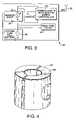
- FIG. 4is an isometric view of a sensor housing in accordance with the present invention.
- FIG. 5is an isometric view of a sensor housing in accordance with the present invention.
- FIG. 6is a diagram of a spinal fusion orthopedic implant equipped with the present invention.
- FIG. 7is a block diagram of the system of the present invention.
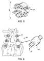
- FIG. 8is an isometric view of a sensor housing in accordance with one embodiment of the present invention.
- FIG. 9is a view of a sensor housing taken in the direction of arrow 9 of FIG. 8 .
- FIG. 10is an isometric view of a sensor housing in accordance with one embodiment of the present invention.
- FIG. 11is a view of a sensor housing taken in the direction of arrow 11 of FIG. 10 .
- a system 10 for measuring and remotely monitoring strain in an element 1 subject theretoincludes a sensor 20 capable of measuring static and dynamic strain in the element 1 , a telemetry circuit 40 that transmits sensor 20 data, and a remotely located reader module 60 for receiving the transmitted sensor data.
- the sensor 20can be a miniaturized strain gauge, a MEMS (micro electrical mechanical system) sensor, a surface acoustic wave (SAW) sensor, or a capacitance-type sensor adapted to measure strain in an element, or any other strain sensor capable of measuring both static and dynamic strain in a loaded element 1 .
- MEMSmicro electrical mechanical system
- SAWsurface acoustic wave
- a capacitance-type cantilevered beam sensor 20may be employed with the present invention, wherein a capacitance beam 22 acting as a first parallel plat depends from a pivot 24 secured to a slipcover 26 that permits the sensor to be mounted on the strained element 1 , or alternatively on a housing encapsulating the sensor 20 , in addition to acting as the second parallel plat of the sensor 20 .
- the distance between the beam 22 and slipcover 26varies, thereby varying the capacitance of the sensor.
- the sensor 20is thus capable of measuring the deformation or curvature of element 1 as it is subjected to varying loads. As element 1 is loaded its surface deforms, typically such deformation being in the nature of a convex or concave curvature, thereby changing the capacitance between beam 22 and element 1 .
- a sensor 20 capable of measuring static and dynamic strainmay be employed in place of a capacitive beam sensor, since the variable strain signal produced thereby is representative of surface deformation as element 1 flexes or curves.
- a passive telemetry circuit 40is provided (requiring no battery) that includes an inductor L R and capacitor C R forming a simple tank circuit.
- the reader moduleutilizes an antenna coil 62 that transmits at a predetermined frequency, for example 125 KHz, as is common in radio frequency identification device (RFID) circuitry.
- RFIDradio frequency identification device
- the resonant frequency of the telemetry circuit 40changes responsive to the strain.
- the reader 60detects the corresponding resonant frequency signal produced by the telemetry circuit 40 that is indicative of strain in the element 1 .
- a simple power circuit 44is included to provide rectified dc power derived from the power transmitted from the reader antenna 62 to the telemetry circuit 40 to be utilized to power additional circuitry such as signal processing (not shown) for the sensor 20 signal.
- an alternative telemetry circuit 40is shown, whereby a miniature power supply 46 , for example a lithium battery, is used to actively power the telemetry circuit 40 .
- a real time clock 48is used as a switch to energize and de-energize the entire circuit 40 at predetermined intervals in order to preserve battery 46 power.
- a transceiver integrated circuit (IC) 50is used to accept the sensor 20 input 22 and transmit the input to the remote reader 60 .
- ICtransceiver integrated circuit
- This embodiment of the present inventionpermits the use of a conventional strain gauge as a sensor 20 , since sufficient dc power is readily available from the battery 46 , as well as on-board micro-controller for processing and storing the data from the sensor 20 .
- the sensor 20 datais then transmitted via radio frequency communication through an antenna 52 .
- This embodiment of the present inventionalso permits the use of a variety of commercially available IC packages as a transceiver 50 for use in storing and transmitting the sensor 20 data.
- FIGS. 4 and 5depict two housings 80 that may be used to encapsulate the sensor 20 and telemetry circuit, and are advantageous for use in inter-vivo applications. These housings 80 are suitable for use where the sensor 20 is sued to measure strain in a rod or similar device, for example as a component of an orthopedic implant.
- FIG. 6shows a spinal fusion implant 90 comprising a plurality of rods 92 affixed by a plurality of pedicle screws 94 both above and below a pair of vertebrae being fused.
- This orthopedic implant 90is used to stabilize and support the surgically fused vertebrae until the healing process fuses the vertebrae sufficiently to bear the load required of the spine. Over time as the fused vertebrae heal, there is an in vivo load transfer from the implant 90 to the spine.
- a physiciancan determine the progression of the spinal fusion.
- the housings 80may be made of any bio-compatible material such as polyethylene or a similar non-reactive polymer to permit the sensor 20 and telemetry circuit 40 encapsulated therein to be implanted in a living organism. As best seen in FIGS. 6 and 7 the substantially annular housings 80 can be placed around the circumference of an implant rod 92 such that the sensor 20 is disposed on the rod 92 surface. Furthermore, the housings 80 may comprise two interlocking halves to facilitate the placement of the telemetry circuit 40 and sensor 20 within the housing, and permit ease of installation of the entire assembly onto an implant rod.
- This feature of the inventionpermits a sensor 20 and concomitant telemetry circuit 40 to be affixed to the implant rod or rods 92 in advance of the surgery, thereby reducing operating time. While the specific housing embodiments shown in FIGS. 4 and 5 are adapted to be used with cylindrical rods, it will be appreciated by one or ordinary skill that a variety of implant shapes can be accommodated by modification of the interior surface of the housing 80 .
- FIGS. 8-11depict an alternative housing 80 which is shaped as a truncated annulus having an interior surface 82 that conforms closely to the exterior shape of element 1 or rods 92 , thereby facilitating placement around a portion of cylindrical rods 92 .
- the housing 80further comprises annular side portions 84 that extend more than half way around the circumference of rod 92 . This feature of the invention permits the housing 80 and concomitant sensor 20 to be snapped into place over rod 92 , thereby facilitating installation.
- interior surfaces 82are shown as generally annular in shape, any shape required to mate with rod 92 or element 1 may be employed as an interior surface shape.
- Housing 80may also include a flat portion 85 on an exterior surface thereof, to permit positive placement of sensor 20 thereon.
- a housing cover 86may comprise a mating surface 87 that permits housing cover 86 to closely mate with the exterior surface of housing 80 .
- Housing cover 86also includes an aperture 88 in an interior portion thereof that provides room for antenna 62 and sensor 20 that is disposed on flat portion 85 of housing 80 .
- This feature of the inventionpermits sensor 20 and concomitant electronic components to be situated on housing 20 flat portion, thence covered and sealed from damage by housing cover 86 .
- mating surface 87 of cover 86 and interior surface 82 of housing 80are shown as generally annular in shape, a wide variety of complementary surface shapes may be employed without departing from the scope of the present invention.
- the senor 20may be placed so that it does not directly contact the surface of the implant rod 90 , but instead is in contact with the interior surface of the housing 80 .
- the housing 80is also strained, thereby imparting strain to the sensor 20 , and even amplifying the strain in the rod 90 to some extent.
- a compact battery-powered reader 100 and an associated flash card memory 102may be employed as a belt or pocket unit, similar to a conventional pager, that may be located on a belt or other location proximate to an implanted orthopedic device instrumented with the invention.
- the compact reader 100provides sufficient power to the sensor 20 and telemetry circuit 40 to receive sensor 20 data at pre-determined intervals throughout the day whereupon it is stored in the memory 102 .
- the flash memory card 102may be removed from the reader 100 periodically, and the data stored thereon may be downloaded to a conventional computer (not shown) for use by a physician.
- This feature of the inventionpermits the physician to monitor in near real-time the progress of the fusion process, or other strain data indicative of the progress of orthopedic implant surgery.
- the flash memory card 102can be readily used to transmit the stored strain data to a conventional personal computer, the physician can have near real-time access to the data in event of an emergency or related concern from a recovering patient.
- a conventional microcomputer control module 110may be employed in a communication with the reader 60 to store and process the sensor 20 data and may be used to construct graphical representations of the strain data, or transmit the data to others.
Landscapes
- Physics & Mathematics (AREA)
- General Physics & Mathematics (AREA)
- Health & Medical Sciences (AREA)
- Life Sciences & Earth Sciences (AREA)
- Engineering & Computer Science (AREA)
- Surgery (AREA)
- General Health & Medical Sciences (AREA)
- Veterinary Medicine (AREA)
- Biomedical Technology (AREA)
- Heart & Thoracic Surgery (AREA)
- Medical Informatics (AREA)
- Molecular Biology (AREA)
- Pathology (AREA)
- Animal Behavior & Ethology (AREA)
- Public Health (AREA)
- Biophysics (AREA)
- Computer Networks & Wireless Communication (AREA)
- Acoustics & Sound (AREA)
- Power Engineering (AREA)
- Chemical & Material Sciences (AREA)
- Analytical Chemistry (AREA)
- Biochemistry (AREA)
- Immunology (AREA)
- Orthopedic Medicine & Surgery (AREA)
- Nuclear Medicine, Radiotherapy & Molecular Imaging (AREA)
- Prostheses (AREA)
- Measurement Of The Respiration, Hearing Ability, Form, And Blood Characteristics Of Living Organisms (AREA)
Abstract
Description
Claims (11)
Priority Applications (4)
| Application Number | Priority Date | Filing Date | Title |
|---|---|---|---|
| US11/226,023US7357037B2 (en) | 2002-07-10 | 2005-09-14 | Strain sensing system |
| KR1020087008911AKR101006650B1 (en) | 2005-09-14 | 2006-09-14 | Strain Sensing System for Telemetry |
| EP20060824960EP1951109B1 (en) | 2005-09-14 | 2006-09-14 | Telemetric strain sensing system |
| PCT/US2006/035871WO2007033333A1 (en) | 2005-09-14 | 2006-09-14 | Telemetric strain sensing system |
Applications Claiming Priority (3)
| Application Number | Priority Date | Filing Date | Title |
|---|---|---|---|
| US39460702P | 2002-07-10 | 2002-07-10 | |
| US10/616,599US20040011137A1 (en) | 2002-07-10 | 2003-07-10 | Strain sensing system |
| US11/226,023US7357037B2 (en) | 2002-07-10 | 2005-09-14 | Strain sensing system |
Related Parent Applications (1)
| Application Number | Title | Priority Date | Filing Date |
|---|---|---|---|
| US10/616,599Continuation-In-PartUS20040011137A1 (en) | 2002-07-10 | 2003-07-10 | Strain sensing system |
Publications (2)
| Publication Number | Publication Date |
|---|---|
| US20060032314A1 US20060032314A1 (en) | 2006-02-16 |
| US7357037B2true US7357037B2 (en) | 2008-04-15 |
Family
ID=37649470
Family Applications (1)
| Application Number | Title | Priority Date | Filing Date |
|---|---|---|---|
| US11/226,023Expired - LifetimeUS7357037B2 (en) | 2002-07-10 | 2005-09-14 | Strain sensing system |
Country Status (4)
| Country | Link |
|---|---|
| US (1) | US7357037B2 (en) |
| EP (1) | EP1951109B1 (en) |
| KR (1) | KR101006650B1 (en) |
| WO (1) | WO2007033333A1 (en) |
Cited By (52)
| Publication number | Priority date | Publication date | Assignee | Title |
|---|---|---|---|---|
| US20070233065A1 (en)* | 2006-02-17 | 2007-10-04 | Sdgi Holdings, Inc. | Dynamic treatment system and method of use |
| US20080208516A1 (en)* | 2004-11-04 | 2008-08-28 | Smith & Nephew, Inc. | Cycle and Load Measurement Device |
| US20080300597A1 (en)* | 2005-08-23 | 2008-12-04 | Smith & Nephew, Inc. | Telemetric Orthopaedic Implant |
| US20100145387A1 (en)* | 2006-01-27 | 2010-06-10 | Warsaw Orthopedic, Inc. | Spinal implants including a sensor and methods of use |
| US20100152621A1 (en)* | 2007-02-23 | 2010-06-17 | Smith & Nephew, Inc. | Processing sensed accelerometer data for determination of bone healing |
| US20100219842A1 (en)* | 2009-03-02 | 2010-09-02 | The University Of Vermont And State Agricultural College | Detection Circuit for Use in Various Types of Capacitive Transducers and a Transducer Including Such a Circuit |
| US20110004124A1 (en)* | 2009-07-01 | 2011-01-06 | Medtronic, Inc. | Implantable medical device including mechanical stress sensor |
| US20110152725A1 (en)* | 2008-09-02 | 2011-06-23 | Christian M. Puttlitz Consulting, Llc | Biomems sensor and apparatuses and methods therefor |
| US20110205083A1 (en)* | 2007-09-06 | 2011-08-25 | Smith & Nephew, Inc. | System and method for communicating with a telemetric implant |
| US8704124B2 (en) | 2009-01-29 | 2014-04-22 | Smith & Nephew, Inc. | Low temperature encapsulate welding |
| US20160128573A1 (en)* | 2014-11-10 | 2016-05-12 | Intellirod Spine, Inc. | Implantable sensors and methods of use |
| USRE46582E1 (en)* | 2004-06-07 | 2017-10-24 | DePuy Synthes Products, Inc. | Orthopaedic implant with sensors |
| US20180069439A1 (en)* | 2015-02-19 | 2018-03-08 | Arizona Board Of Regents On Behalf Of Arizona State University | Virtual magnetic transmission lines for communication and power transfer in conducting media |
| US10016220B2 (en) | 2011-11-01 | 2018-07-10 | Nuvasive Specialized Orthopedics, Inc. | Adjustable magnetic devices and methods of using same |
| US10039661B2 (en) | 2006-10-20 | 2018-08-07 | Nuvasive Specialized Orthopedics, Inc. | Adjustable implant and method of use |
| US10238427B2 (en) | 2015-02-19 | 2019-03-26 | Nuvasive Specialized Orthopedics, Inc. | Systems and methods for vertebral adjustment |
| US10271885B2 (en) | 2014-12-26 | 2019-04-30 | Nuvasive Specialized Orthopedics, Inc. | Systems and methods for distraction |
| US10285637B1 (en)* | 2014-11-10 | 2019-05-14 | University Of Louisville Research Foundation, Inc. | Apparatus for sensing strain on a spinal fusion rod |
| US10349995B2 (en) | 2007-10-30 | 2019-07-16 | Nuvasive Specialized Orthopedics, Inc. | Skeletal manipulation method |
| US10405891B2 (en) | 2010-08-09 | 2019-09-10 | Nuvasive Specialized Orthopedics, Inc. | Maintenance feature in magnetic implant |
| US10478232B2 (en) | 2009-04-29 | 2019-11-19 | Nuvasive Specialized Orthopedics, Inc. | Interspinous process device and method |
| US10517643B2 (en) | 2009-02-23 | 2019-12-31 | Nuvasive Specialized Orthopedics, Inc. | Non-invasive adjustable distraction system |
| US10617453B2 (en) | 2015-10-16 | 2020-04-14 | Nuvasive Specialized Orthopedics, Inc. | Adjustable devices for treating arthritis of the knee |
| US10646262B2 (en) | 2011-02-14 | 2020-05-12 | Nuvasive Specialized Orthopedics, Inc. | System and method for altering rotational alignment of bone sections |
| US10660675B2 (en) | 2010-06-30 | 2020-05-26 | Nuvasive Specialized Orthopedics, Inc. | External adjustment device for distraction device |
| US10729470B2 (en) | 2008-11-10 | 2020-08-04 | Nuvasive Specialized Orthopedics, Inc. | External adjustment device for distraction device |
| US10743794B2 (en) | 2011-10-04 | 2020-08-18 | Nuvasive Specialized Orthopedics, Inc. | Devices and methods for non-invasive implant length sensing |
| US10751094B2 (en) | 2013-10-10 | 2020-08-25 | Nuvasive Specialized Orthopedics, Inc. | Adjustable spinal implant |
| US10835290B2 (en) | 2015-12-10 | 2020-11-17 | Nuvasive Specialized Orthopedics, Inc. | External adjustment device for distraction device |
| US10918425B2 (en) | 2016-01-28 | 2021-02-16 | Nuvasive Specialized Orthopedics, Inc. | System and methods for bone transport |
| US11191579B2 (en) | 2012-10-29 | 2021-12-07 | Nuvasive Specialized Orthopedics, Inc. | Adjustable devices for treating arthritis of the knee |
| US11202707B2 (en) | 2008-03-25 | 2021-12-21 | Nuvasive Specialized Orthopedics, Inc. | Adjustable implant system |
| US11207110B2 (en) | 2009-09-04 | 2021-12-28 | Nuvasive Specialized Orthopedics, Inc. | Bone growth device and method |
| US11246694B2 (en) | 2014-04-28 | 2022-02-15 | Nuvasive Specialized Orthopedics, Inc. | System for informational magnetic feedback in adjustable implants |
| WO2022040102A1 (en)* | 2020-08-17 | 2022-02-24 | Arizona Board Of Regents On Behalf Of The University Of Arizona | An implantable miniaturized and soft wireless sensing device to monitor tissue and bone deformation |
| USRE49061E1 (en) | 2012-10-18 | 2022-05-10 | Nuvasive Specialized Orthopedics, Inc. | Intramedullary implants for replacing lost bone |
| US11333409B2 (en)* | 2019-02-19 | 2022-05-17 | Sumitomo Heavy Industries, Ltd. | Cryocooler, cryocooler diagnosis device, and cryocooler diagnosis method |
| US11357547B2 (en) | 2014-10-23 | 2022-06-14 | Nuvasive Specialized Orthopedics Inc. | Remotely adjustable interactive bone reshaping implant |
| US11357549B2 (en) | 2004-07-02 | 2022-06-14 | Nuvasive Specialized Orthopedics, Inc. | Expandable rod system to treat scoliosis and method of using the same |
| US11577097B2 (en) | 2019-02-07 | 2023-02-14 | Nuvasive Specialized Orthopedics, Inc. | Ultrasonic communication in medical devices |
| US11589901B2 (en) | 2019-02-08 | 2023-02-28 | Nuvasive Specialized Orthopedics, Inc. | External adjustment device |
| US11696836B2 (en) | 2013-08-09 | 2023-07-11 | Nuvasive, Inc. | Lordotic expandable interbody implant |
| US11737787B1 (en) | 2021-05-27 | 2023-08-29 | Nuvasive, Inc. | Bone elongating devices and methods of use |
| US11766252B2 (en) | 2013-07-31 | 2023-09-26 | Nuvasive Specialized Orthopedics, Inc. | Noninvasively adjustable suture anchors |
| US11801187B2 (en) | 2016-02-10 | 2023-10-31 | Nuvasive Specialized Orthopedics, Inc. | Systems and methods for controlling multiple surgical variables |
| US11806054B2 (en) | 2021-02-23 | 2023-11-07 | Nuvasive Specialized Orthopedics, Inc. | Adjustable implant, system and methods |
| US11839410B2 (en) | 2012-06-15 | 2023-12-12 | Nuvasive Inc. | Magnetic implants with improved anatomical compatibility |
| US11857226B2 (en) | 2013-03-08 | 2024-01-02 | Nuvasive Specialized Orthopedics | Systems and methods for ultrasonic detection of device distraction |
| US11925389B2 (en) | 2008-10-13 | 2024-03-12 | Nuvasive Specialized Orthopedics, Inc. | Spinal distraction system |
| US12023073B2 (en) | 2021-08-03 | 2024-07-02 | Nuvasive Specialized Orthopedics, Inc. | Adjustable implant |
| US12213708B2 (en) | 2020-09-08 | 2025-02-04 | Nuvasive Specialized Orthopedics, Inc. | Remote control module for adjustable implants |
| US12396679B2 (en) | 2018-07-19 | 2025-08-26 | Warsaw Orthopedic, Inc. | System and method for post-operative assessment of spinal motion and implant-based strain correlation |
Families Citing this family (19)
| Publication number | Priority date | Publication date | Assignee | Title |
|---|---|---|---|---|
| WO2006010037A2 (en) | 2004-07-08 | 2006-01-26 | Deborah Schenberger | Strain monitoring system and apparatus |
| US7328131B2 (en)* | 2006-02-01 | 2008-02-05 | Medtronic, Inc. | Implantable pedometer |
| US7993269B2 (en) | 2006-02-17 | 2011-08-09 | Medtronic, Inc. | Sensor and method for spinal monitoring |
| DE102006034041A1 (en)* | 2006-07-19 | 2008-01-31 | Berufsgenossenschaftlicher Verein für Heilbehandlung Hamburg e.V. Berufsgenossenschaftliches Unfallkrankenhaus Hamburg | Wireless strain gauge measuring system for use in e.g. mechanical engineering, has strain gauge implemented as single strip, where system is implemented to permit application of strip, so that data and energy are exchanged for operation |
| EP2160581B1 (en)* | 2007-07-02 | 2018-03-28 | Contitech AG | Expansion sensor and corresponding sensor arrangement |
| US8915866B2 (en)* | 2008-01-18 | 2014-12-23 | Warsaw Orthopedic, Inc. | Implantable sensor and associated methods |
| WO2009105817A1 (en)* | 2008-02-29 | 2009-09-03 | Silesco Pty Ltd | An orthopaedic safety system |
| US20100094303A1 (en)* | 2008-10-13 | 2010-04-15 | Arvin Chang | Spinal distraction system |
| US8685093B2 (en)* | 2009-01-23 | 2014-04-01 | Warsaw Orthopedic, Inc. | Methods and systems for diagnosing, treating, or tracking spinal disorders |
| US8126736B2 (en)* | 2009-01-23 | 2012-02-28 | Warsaw Orthopedic, Inc. | Methods and systems for diagnosing, treating, or tracking spinal disorders |
| US8376937B2 (en)* | 2010-01-28 | 2013-02-19 | Warsaw Orhtopedic, Inc. | Tissue monitoring surgical retractor system |
| EP3486667B1 (en)* | 2010-04-06 | 2022-11-16 | FMC Technologies, Inc. | Inductively interrogated passive sensor apparatus |
| FR2976073B1 (en)* | 2011-05-31 | 2013-06-28 | Centre Nat Rech Scient | STRAIN SENSOR |
| US9078711B2 (en) | 2012-06-06 | 2015-07-14 | Ellipse Technologies, Inc. | Devices and methods for detection of slippage of magnetic coupling in implantable medical devices |
| WO2014043263A1 (en) | 2012-09-11 | 2014-03-20 | Shahoian Erik J | Systems and methods for haptic stimulation |
| US10940079B2 (en) | 2015-05-19 | 2021-03-09 | Sparq Laboratories, Llc | Male and female sexual aid with wireless capabilities |
| CN105300672B (en)* | 2015-10-05 | 2018-01-02 | 上海大学 | The external fatigue tester of alternate load stepless adjustable internal fixation of spine device |
| DE102016105789A1 (en)* | 2016-03-30 | 2017-10-05 | Aesculap Ag | Sensory encoder system |
| CN115414137A (en)* | 2022-11-04 | 2022-12-02 | 清华大学 | Label circuit, bone implant, bone strain detection system and method |
Citations (11)
| Publication number | Priority date | Publication date | Assignee | Title |
|---|---|---|---|---|
| US5585571A (en) | 1990-03-03 | 1996-12-17 | Lonsdale; Anthony | Method and apparatus for measuring strain |
| WO2000005610A1 (en) | 1997-07-25 | 2000-02-03 | Raytheon Company | Fiber optic connector |
| WO2000056210A1 (en) | 1999-03-24 | 2000-09-28 | Noveon Ip Holdings Corp. | Remotely interrogated diagnostic implant device with electrically passive sensor |
| WO2001037726A1 (en) | 1999-11-23 | 2001-05-31 | Noveon Ip Holding Corp. | Remotely interrogated medical implant with sensor |
| US20020082665A1 (en) | 1999-07-07 | 2002-06-27 | Medtronic, Inc. | System and method of communicating between an implantable medical device and a remote computer system or health care provider |
| WO2004005872A2 (en) | 2002-07-10 | 2004-01-15 | Orthodata Technologies Llc | Strain sensing system |
| US6706005B2 (en)* | 2000-08-25 | 2004-03-16 | The Cleveland Clinic Foundation | Apparatus and method for assessing loads on adjacent bones |
| US20050288604A1 (en)* | 2002-09-26 | 2005-12-29 | Eigler Neal L | Implantable pressure transducer system optimized to correct environmental factors |
| US7047074B2 (en)* | 2001-02-20 | 2006-05-16 | Biophan Technologies, Inc. | Electromagnetic interference immune tissue invasive system |
| US7161484B2 (en)* | 2001-04-17 | 2007-01-09 | Micrel Medical Devices S.A. | System for monitoring medical parameters |
| US7160258B2 (en)* | 2001-06-26 | 2007-01-09 | Entrack, Inc. | Capsule and method for treating or diagnosing the intestinal tract |
Family Cites Families (1)
| Publication number | Priority date | Publication date | Assignee | Title |
|---|---|---|---|---|
| US6636769B2 (en)* | 2000-12-18 | 2003-10-21 | Biosense, Inc. | Telemetric medical system and method |
- 2005
- 2005-09-14USUS11/226,023patent/US7357037B2/ennot_activeExpired - Lifetime
- 2006
- 2006-09-14KRKR1020087008911Apatent/KR101006650B1/ennot_activeExpired - Fee Related
- 2006-09-14EPEP20060824960patent/EP1951109B1/enactiveActive
- 2006-09-14WOPCT/US2006/035871patent/WO2007033333A1/enactiveApplication Filing
Patent Citations (11)
| Publication number | Priority date | Publication date | Assignee | Title |
|---|---|---|---|---|
| US5585571A (en) | 1990-03-03 | 1996-12-17 | Lonsdale; Anthony | Method and apparatus for measuring strain |
| WO2000005610A1 (en) | 1997-07-25 | 2000-02-03 | Raytheon Company | Fiber optic connector |
| WO2000056210A1 (en) | 1999-03-24 | 2000-09-28 | Noveon Ip Holdings Corp. | Remotely interrogated diagnostic implant device with electrically passive sensor |
| US20020082665A1 (en) | 1999-07-07 | 2002-06-27 | Medtronic, Inc. | System and method of communicating between an implantable medical device and a remote computer system or health care provider |
| WO2001037726A1 (en) | 1999-11-23 | 2001-05-31 | Noveon Ip Holding Corp. | Remotely interrogated medical implant with sensor |
| US6706005B2 (en)* | 2000-08-25 | 2004-03-16 | The Cleveland Clinic Foundation | Apparatus and method for assessing loads on adjacent bones |
| US7047074B2 (en)* | 2001-02-20 | 2006-05-16 | Biophan Technologies, Inc. | Electromagnetic interference immune tissue invasive system |
| US7161484B2 (en)* | 2001-04-17 | 2007-01-09 | Micrel Medical Devices S.A. | System for monitoring medical parameters |
| US7160258B2 (en)* | 2001-06-26 | 2007-01-09 | Entrack, Inc. | Capsule and method for treating or diagnosing the intestinal tract |
| WO2004005872A2 (en) | 2002-07-10 | 2004-01-15 | Orthodata Technologies Llc | Strain sensing system |
| US20050288604A1 (en)* | 2002-09-26 | 2005-12-29 | Eigler Neal L | Implantable pressure transducer system optimized to correct environmental factors |
Cited By (102)
| Publication number | Priority date | Publication date | Assignee | Title |
|---|---|---|---|---|
| USRE46582E1 (en)* | 2004-06-07 | 2017-10-24 | DePuy Synthes Products, Inc. | Orthopaedic implant with sensors |
| US11712268B2 (en) | 2004-07-02 | 2023-08-01 | Nuvasive Specialized Orthopedics, Inc. | Expandable rod system to treat scoliosis and method of using the same |
| US11357549B2 (en) | 2004-07-02 | 2022-06-14 | Nuvasive Specialized Orthopedics, Inc. | Expandable rod system to treat scoliosis and method of using the same |
| US20080208516A1 (en)* | 2004-11-04 | 2008-08-28 | Smith & Nephew, Inc. | Cycle and Load Measurement Device |
| US8388553B2 (en) | 2004-11-04 | 2013-03-05 | Smith & Nephew, Inc. | Cycle and load measurement device |
| US20080300597A1 (en)* | 2005-08-23 | 2008-12-04 | Smith & Nephew, Inc. | Telemetric Orthopaedic Implant |
| US8721643B2 (en) | 2005-08-23 | 2014-05-13 | Smith & Nephew, Inc. | Telemetric orthopaedic implant |
| US8486070B2 (en) | 2005-08-23 | 2013-07-16 | Smith & Nephew, Inc. | Telemetric orthopaedic implant |
| US8216279B2 (en)* | 2006-01-27 | 2012-07-10 | Warsaw Orthopedic, Inc. | Spinal implant kits with multiple interchangeable modules |
| US20100145387A1 (en)* | 2006-01-27 | 2010-06-10 | Warsaw Orthopedic, Inc. | Spinal implants including a sensor and methods of use |
| US20070233065A1 (en)* | 2006-02-17 | 2007-10-04 | Sdgi Holdings, Inc. | Dynamic treatment system and method of use |
| US8016859B2 (en)* | 2006-02-17 | 2011-09-13 | Medtronic, Inc. | Dynamic treatment system and method of use |
| US11234849B2 (en) | 2006-10-20 | 2022-02-01 | Nuvasive Specialized Orthopedics, Inc. | Adjustable implant and method of use |
| US10039661B2 (en) | 2006-10-20 | 2018-08-07 | Nuvasive Specialized Orthopedics, Inc. | Adjustable implant and method of use |
| US11672684B2 (en) | 2006-10-20 | 2023-06-13 | Nuvasive Specialized Orthopedics, Inc. | Adjustable implant and method of use |
| US20100152621A1 (en)* | 2007-02-23 | 2010-06-17 | Smith & Nephew, Inc. | Processing sensed accelerometer data for determination of bone healing |
| US9445720B2 (en) | 2007-02-23 | 2016-09-20 | Smith & Nephew, Inc. | Processing sensed accelerometer data for determination of bone healing |
| US8570187B2 (en) | 2007-09-06 | 2013-10-29 | Smith & Nephew, Inc. | System and method for communicating with a telemetric implant |
| US20110205083A1 (en)* | 2007-09-06 | 2011-08-25 | Smith & Nephew, Inc. | System and method for communicating with a telemetric implant |
| US11871974B2 (en) | 2007-10-30 | 2024-01-16 | Nuvasive Specialized Orthopedics, Inc. | Skeletal manipulation method |
| US11172972B2 (en) | 2007-10-30 | 2021-11-16 | Nuvasive Specialized Orthopedics, Inc. | Skeletal manipulation method |
| US10349995B2 (en) | 2007-10-30 | 2019-07-16 | Nuvasive Specialized Orthopedics, Inc. | Skeletal manipulation method |
| US11202707B2 (en) | 2008-03-25 | 2021-12-21 | Nuvasive Specialized Orthopedics, Inc. | Adjustable implant system |
| US12076241B2 (en) | 2008-03-25 | 2024-09-03 | Nuvasive Specialized Orthopedics, Inc. | Adjustable implant system |
| US9326728B2 (en) | 2008-09-02 | 2016-05-03 | Innovative In Vivo Sensing, Llc | BioMEMS sensor and apparatuses and methods therefor |
| US20110152725A1 (en)* | 2008-09-02 | 2011-06-23 | Christian M. Puttlitz Consulting, Llc | Biomems sensor and apparatuses and methods therefor |
| US11925389B2 (en) | 2008-10-13 | 2024-03-12 | Nuvasive Specialized Orthopedics, Inc. | Spinal distraction system |
| US11974782B2 (en) | 2008-11-10 | 2024-05-07 | Nuvasive Specialized Orthopedics, Inc. | External adjustment device for distraction device |
| US10729470B2 (en) | 2008-11-10 | 2020-08-04 | Nuvasive Specialized Orthopedics, Inc. | External adjustment device for distraction device |
| US8704124B2 (en) | 2009-01-29 | 2014-04-22 | Smith & Nephew, Inc. | Low temperature encapsulate welding |
| US10517643B2 (en) | 2009-02-23 | 2019-12-31 | Nuvasive Specialized Orthopedics, Inc. | Non-invasive adjustable distraction system |
| US11918254B2 (en) | 2009-02-23 | 2024-03-05 | Nuvasive Specialized Orthopedics Inc. | Adjustable implant system |
| US11304729B2 (en) | 2009-02-23 | 2022-04-19 | Nuvasive Specialized Orthhopedics, Inc. | Non-invasive adjustable distraction system |
| US20100219842A1 (en)* | 2009-03-02 | 2010-09-02 | The University Of Vermont And State Agricultural College | Detection Circuit for Use in Various Types of Capacitive Transducers and a Transducer Including Such a Circuit |
| US8427178B2 (en)* | 2009-03-02 | 2013-04-23 | The University Of Vermont And State Agricultural College | Detection circuit for use in various types of capacitive transducers and a transducer including such a circuit |
| US10478232B2 (en) | 2009-04-29 | 2019-11-19 | Nuvasive Specialized Orthopedics, Inc. | Interspinous process device and method |
| US11602380B2 (en) | 2009-04-29 | 2023-03-14 | Nuvasive Specialized Orthopedics, Inc. | Interspinous process device and method |
| US20110004124A1 (en)* | 2009-07-01 | 2011-01-06 | Medtronic, Inc. | Implantable medical device including mechanical stress sensor |
| US11944358B2 (en) | 2009-09-04 | 2024-04-02 | Nuvasive Specialized Orthopedics, Inc. | Bone growth device and method |
| US11207110B2 (en) | 2009-09-04 | 2021-12-28 | Nuvasive Specialized Orthopedics, Inc. | Bone growth device and method |
| US11497530B2 (en) | 2010-06-30 | 2022-11-15 | Nuvasive Specialized Orthopedics, Inc. | External adjustment device for distraction device |
| US12178477B2 (en) | 2010-06-30 | 2024-12-31 | Globus Medical Inc. | External adjustment device for distraction system |
| US10660675B2 (en) | 2010-06-30 | 2020-05-26 | Nuvasive Specialized Orthopedics, Inc. | External adjustment device for distraction device |
| US10405891B2 (en) | 2010-08-09 | 2019-09-10 | Nuvasive Specialized Orthopedics, Inc. | Maintenance feature in magnetic implant |
| US10646262B2 (en) | 2011-02-14 | 2020-05-12 | Nuvasive Specialized Orthopedics, Inc. | System and method for altering rotational alignment of bone sections |
| US12290290B2 (en) | 2011-02-14 | 2025-05-06 | Nuvasive, Inc. | System and method for altering rotational alignment of bone sections |
| US11406432B2 (en) | 2011-02-14 | 2022-08-09 | Nuvasive Specialized Orthopedics, Inc. | System and method for altering rotational alignment of bone sections |
| US10743794B2 (en) | 2011-10-04 | 2020-08-18 | Nuvasive Specialized Orthopedics, Inc. | Devices and methods for non-invasive implant length sensing |
| US11445939B2 (en) | 2011-10-04 | 2022-09-20 | Nuvasive Specialized Orthopedics, Inc. | Devices and methods for non-invasive implant length sensing |
| US10016220B2 (en) | 2011-11-01 | 2018-07-10 | Nuvasive Specialized Orthopedics, Inc. | Adjustable magnetic devices and methods of using same |
| US10349982B2 (en) | 2011-11-01 | 2019-07-16 | Nuvasive Specialized Orthopedics, Inc. | Adjustable magnetic devices and methods of using same |
| US11123107B2 (en) | 2011-11-01 | 2021-09-21 | Nuvasive Specialized Orthopedics, Inc. | Adjustable magnetic devices and methods of using same |
| US11918255B2 (en) | 2011-11-01 | 2024-03-05 | Nuvasive Specialized Orthopedics Inc. | Adjustable magnetic devices and methods of using same |
| US11839410B2 (en) | 2012-06-15 | 2023-12-12 | Nuvasive Inc. | Magnetic implants with improved anatomical compatibility |
| USRE49720E1 (en) | 2012-10-18 | 2023-11-07 | Nuvasive Specialized Orthopedics, Inc. | Intramedullary implants for replacing lost bone |
| USRE49061E1 (en) | 2012-10-18 | 2022-05-10 | Nuvasive Specialized Orthopedics, Inc. | Intramedullary implants for replacing lost bone |
| US11871971B2 (en) | 2012-10-29 | 2024-01-16 | Nuvasive Specialized Orthopedics, Inc. | Adjustable devices for treating arthritis of the knee |
| US11213330B2 (en) | 2012-10-29 | 2022-01-04 | Nuvasive Specialized Orthopedics, Inc. | Adjustable devices for treating arthritis of the knee |
| US11191579B2 (en) | 2012-10-29 | 2021-12-07 | Nuvasive Specialized Orthopedics, Inc. | Adjustable devices for treating arthritis of the knee |
| US11857226B2 (en) | 2013-03-08 | 2024-01-02 | Nuvasive Specialized Orthopedics | Systems and methods for ultrasonic detection of device distraction |
| US12329374B2 (en) | 2013-07-31 | 2025-06-17 | Nuvasive Specialized Orthopedics Inc. | Noninvasively adjustable suture anchors |
| US11766252B2 (en) | 2013-07-31 | 2023-09-26 | Nuvasive Specialized Orthopedics, Inc. | Noninvasively adjustable suture anchors |
| US11696836B2 (en) | 2013-08-09 | 2023-07-11 | Nuvasive, Inc. | Lordotic expandable interbody implant |
| US12213893B2 (en) | 2013-08-09 | 2025-02-04 | Nuvasive, Inc. | Lordotic expandable interbody implant and method of using same |
| US10751094B2 (en) | 2013-10-10 | 2020-08-25 | Nuvasive Specialized Orthopedics, Inc. | Adjustable spinal implant |
| US11576702B2 (en) | 2013-10-10 | 2023-02-14 | Nuvasive Specialized Orthopedics, Inc. | Adjustable spinal implant |
| US11246694B2 (en) | 2014-04-28 | 2022-02-15 | Nuvasive Specialized Orthopedics, Inc. | System for informational magnetic feedback in adjustable implants |
| US11357547B2 (en) | 2014-10-23 | 2022-06-14 | Nuvasive Specialized Orthopedics Inc. | Remotely adjustable interactive bone reshaping implant |
| US12226127B2 (en) | 2014-10-23 | 2025-02-18 | Nuvasive Specialized Orthopedics, Inc. | Remotely adjustable interactive implantable device |
| US10219699B2 (en)* | 2014-11-10 | 2019-03-05 | Intellirod Spine Inc. | Implantable sensors and methods of use |
| US20160128573A1 (en)* | 2014-11-10 | 2016-05-12 | Intellirod Spine, Inc. | Implantable sensors and methods of use |
| US10285637B1 (en)* | 2014-11-10 | 2019-05-14 | University Of Louisville Research Foundation, Inc. | Apparatus for sensing strain on a spinal fusion rod |
| US11890043B2 (en) | 2014-12-26 | 2024-02-06 | Nuvasive Specialized Orthopedics, Inc. | Systems and methods for distraction |
| US11963705B2 (en) | 2014-12-26 | 2024-04-23 | Nuvasive Specialized Orthopedics, Inc. | Systems and methods for distraction |
| US10271885B2 (en) | 2014-12-26 | 2019-04-30 | Nuvasive Specialized Orthopedics, Inc. | Systems and methods for distraction |
| US11439449B2 (en) | 2014-12-26 | 2022-09-13 | Nuvasive Specialized Orthopedics, Inc. | Systems and methods for distraction |
| US10111612B2 (en)* | 2015-02-19 | 2018-10-30 | Arizona Board Of Regents On Behalf Of Arizona State University | Virtual magnetic transmission lines for communication and power transfer in conducting media |
| US12076051B2 (en) | 2015-02-19 | 2024-09-03 | Nuvasive Specialized Orthopedics, Inc. | Systems and methods for vertebral adjustment |
| US20180069439A1 (en)* | 2015-02-19 | 2018-03-08 | Arizona Board Of Regents On Behalf Of Arizona State University | Virtual magnetic transmission lines for communication and power transfer in conducting media |
| US11612416B2 (en) | 2015-02-19 | 2023-03-28 | Nuvasive Specialized Orthopedics, Inc. | Systems and methods for vertebral adjustment |
| US10238427B2 (en) | 2015-02-19 | 2019-03-26 | Nuvasive Specialized Orthopedics, Inc. | Systems and methods for vertebral adjustment |
| US11596456B2 (en) | 2015-10-16 | 2023-03-07 | Nuvasive Specialized Orthopedics, Inc. | Adjustable devices for treating arthritis of the knee |
| US10617453B2 (en) | 2015-10-16 | 2020-04-14 | Nuvasive Specialized Orthopedics, Inc. | Adjustable devices for treating arthritis of the knee |
| US11504162B2 (en) | 2015-12-10 | 2022-11-22 | Nuvasive Specialized Orthopedics, Inc. | External adjustment device for distraction device |
| US12185982B2 (en) | 2015-12-10 | 2025-01-07 | Globus Medical Inc. | External adjustment device for distraction device |
| US10835290B2 (en) | 2015-12-10 | 2020-11-17 | Nuvasive Specialized Orthopedics, Inc. | External adjustment device for distraction device |
| US10918425B2 (en) | 2016-01-28 | 2021-02-16 | Nuvasive Specialized Orthopedics, Inc. | System and methods for bone transport |
| US11801187B2 (en) | 2016-02-10 | 2023-10-31 | Nuvasive Specialized Orthopedics, Inc. | Systems and methods for controlling multiple surgical variables |
| US12263128B2 (en) | 2016-02-10 | 2025-04-01 | Nuvasive Specialized Orthopedics, Inc. | Systems and methods for controlling multiple surgical variables |
| US12396679B2 (en) | 2018-07-19 | 2025-08-26 | Warsaw Orthopedic, Inc. | System and method for post-operative assessment of spinal motion and implant-based strain correlation |
| US11577097B2 (en) | 2019-02-07 | 2023-02-14 | Nuvasive Specialized Orthopedics, Inc. | Ultrasonic communication in medical devices |
| US12274896B2 (en) | 2019-02-07 | 2025-04-15 | Nuvasive Specialized Orthopedics, Inc. | Ultrasonic communication in medical devices |
| US11589901B2 (en) | 2019-02-08 | 2023-02-28 | Nuvasive Specialized Orthopedics, Inc. | External adjustment device |
| US11333409B2 (en)* | 2019-02-19 | 2022-05-17 | Sumitomo Heavy Industries, Ltd. | Cryocooler, cryocooler diagnosis device, and cryocooler diagnosis method |
| WO2022040102A1 (en)* | 2020-08-17 | 2022-02-24 | Arizona Board Of Regents On Behalf Of The University Of Arizona | An implantable miniaturized and soft wireless sensing device to monitor tissue and bone deformation |
| US12213708B2 (en) | 2020-09-08 | 2025-02-04 | Nuvasive Specialized Orthopedics, Inc. | Remote control module for adjustable implants |
| US12004784B2 (en) | 2021-02-23 | 2024-06-11 | Nuvasive Specialized Orthopedics, Inc. | Adjustable implant, system and methods |
| US11944359B2 (en) | 2021-02-23 | 2024-04-02 | Nuvasive Specialized Orthopedics, Inc. | Adjustable implant, system and methods |
| US11806054B2 (en) | 2021-02-23 | 2023-11-07 | Nuvasive Specialized Orthopedics, Inc. | Adjustable implant, system and methods |
| US12303169B1 (en) | 2021-05-27 | 2025-05-20 | Nuvasive, Inc. | Bone elongating devices and methods of use |
| US11737787B1 (en) | 2021-05-27 | 2023-08-29 | Nuvasive, Inc. | Bone elongating devices and methods of use |
| US12023073B2 (en) | 2021-08-03 | 2024-07-02 | Nuvasive Specialized Orthopedics, Inc. | Adjustable implant |
Also Published As
| Publication number | Publication date |
|---|---|
| EP1951109B1 (en) | 2015-04-29 |
| WO2007033333A1 (en) | 2007-03-22 |
| KR20080070624A (en) | 2008-07-30 |
| KR101006650B1 (en) | 2011-01-10 |
| US20060032314A1 (en) | 2006-02-16 |
| EP1951109A1 (en) | 2008-08-06 |
Similar Documents
| Publication | Publication Date | Title |
|---|---|---|
| US7357037B2 (en) | Strain sensing system | |
| CA2491956C (en) | Strain sensing system | |
| US8486070B2 (en) | Telemetric orthopaedic implant | |
| JP4977020B2 (en) | Strain monitoring system and apparatus | |
| EP1311191B1 (en) | Implantable apparatus for assessing loads on adjacent pair of vertebrae | |
| KR101189732B1 (en) | Orthopaedic implant with sensors | |
| JP5507470B2 (en) | Systems that communicate with implants | |
| EP2114247B1 (en) | Processing sensed accelerometer data for determination of bone healing | |
| EP2440112B1 (en) | Device for processing and transmitting measured signals for monitoring and/or controlling medical implants | |
| CN101291634A (en) | Telemetric Orthopedic Implants | |
| US20230301801A1 (en) | Implant Authentication and Connectivity | |
| WO2020223207A2 (en) | Techniques and medical implant devices for passive measurement of healing information for anatomical structures | |
| JP2018522605A (en) | Kit for assembling a medical device provided with data acquisition means | |
| JP7572429B2 (en) | DEVICE AND METHOD FOR MEASURING, PROCESSING AND TRANSMITTING IMPLANT PARAMETERS - Patent application | |
| Korduba et al. | Radio frequency identification as a testbed for integration of low frequency radio frequency sensors into orthopedic implants |
Legal Events
| Date | Code | Title | Description |
|---|---|---|---|
| AS | Assignment | Owner name:ORTHODATA TECHNOLOGIES LLC, KENTUCKY Free format text:ASSIGNMENT OF ASSIGNORS INTEREST;ASSIGNORS:HNAT, WILLIAM P.;NABER, JOHN F.;WALSH, KEVIN M.;REEL/FRAME:016974/0110 Effective date:20030710 Owner name:ORTHODATA TECNOLOGIES LLC, KENTUCKY Free format text:ASSIGNMENT OF ASSIGNORS INTEREST;ASSIGNORS:HNAT, WILLIAM P.;NABER, JOHN F.;WALSH, KEVIN M.;REEL/FRAME:016974/0089 Effective date:20030710 | |
| STCF | Information on status: patent grant | Free format text:PATENTED CASE | |
| FPAY | Fee payment | Year of fee payment:4 | |
| AS | Assignment | Owner name:ORTHODATA INC., KENTUCKY Free format text:MERGER;ASSIGNOR:ORTHODATA TECHNOLOGIES LLC;REEL/FRAME:029785/0066 Effective date:20080417 | |
| AS | Assignment | Owner name:NATIONAL SCIENCE FOUNDATION, VIRGINIA Free format text:CONFIRMATORY LICENSE;ASSIGNOR:UNIVERSITY OF LOUISVILLE RESEARCH FOUNDATION, INC.;REEL/FRAME:029802/0214 Effective date:20130211 | |
| AS | Assignment | Owner name:NATIONAL SCIENCE FOUNDATION, VIRGINIA Free format text:CONFIRMATORY LICENSE;ASSIGNOR:ORTHODATA INC.;REEL/FRAME:029923/0829 Effective date:20130222 Owner name:ORTHODATA INC., KENTUCKY Free format text:NSF INVENTION RIGHTS WAIVER;ASSIGNOR:NATIONAL SCIENCE FOUNDATION;REEL/FRAME:029926/0320 Effective date:20130228 | |
| CC | Certificate of correction | ||
| AS | Assignment | Owner name:THE DIRECTOR OF THE OHIO DEVELOPMENT SERVICES AGEN Free format text:SECURITY INTEREST;ASSIGNOR:INTELLIROD SPINE, INC.;REEL/FRAME:033012/0683 Effective date:20140512 | |
| FPAY | Fee payment | Year of fee payment:8 | |
| AS | Assignment | Owner name:INTELLIROD SPINE INC., OHIO Free format text:CHANGE OF NAME;ASSIGNOR:ORTHODATA INC.;REEL/FRAME:050718/0036 Effective date:20130913 | |
| FEPP | Fee payment procedure | Free format text:MAINTENANCE FEE REMINDER MAILED (ORIGINAL EVENT CODE: REM.); ENTITY STATUS OF PATENT OWNER: SMALL ENTITY | |
| FEPP | Fee payment procedure | Free format text:11.5 YR SURCHARGE- LATE PMT W/IN 6 MO, SMALL ENTITY (ORIGINAL EVENT CODE: M2556); ENTITY STATUS OF PATENT OWNER: SMALL ENTITY | |
| MAFP | Maintenance fee payment | Free format text:PAYMENT OF MAINTENANCE FEE, 12TH YR, SMALL ENTITY (ORIGINAL EVENT CODE: M2553); ENTITY STATUS OF PATENT OWNER: SMALL ENTITY Year of fee payment:12 | |
| AS | Assignment | Owner name:GLOBUS MEDICAL, INC., PENNSYLVANIA Free format text:ASSIGNMENT OF ASSIGNORS INTEREST;ASSIGNOR:INTELLIROD SPINE, INC.;REEL/FRAME:054808/0008 Effective date:20201230 |