US7356473B2 - Management and assistance system for the deaf - Google Patents
Management and assistance system for the deafDownload PDFInfo
- Publication number
- US7356473B2 US7356473B2US11/041,166US4116605AUS7356473B2US 7356473 B2US7356473 B2US 7356473B2US 4116605 AUS4116605 AUS 4116605AUS 7356473 B2US7356473 B2US 7356473B2
- Authority
- US
- United States
- Prior art keywords
- communication module
- user
- location
- communication
- sounds
- Prior art date
- Legal status (The legal status is an assumption and is not a legal conclusion. Google has not performed a legal analysis and makes no representation as to the accuracy of the status listed.)
- Expired - Lifetime, expires
Links
Images


Classifications
- G—PHYSICS
- G09—EDUCATION; CRYPTOGRAPHY; DISPLAY; ADVERTISING; SEALS
- G09B—EDUCATIONAL OR DEMONSTRATION APPLIANCES; APPLIANCES FOR TEACHING, OR COMMUNICATING WITH, THE BLIND, DEAF OR MUTE; MODELS; PLANETARIA; GLOBES; MAPS; DIAGRAMS
- G09B21/00—Teaching, or communicating with, the blind, deaf or mute
- G09B21/009—Teaching or communicating with deaf persons
- G—PHYSICS
- G09—EDUCATION; CRYPTOGRAPHY; DISPLAY; ADVERTISING; SEALS
- G09B—EDUCATIONAL OR DEMONSTRATION APPLIANCES; APPLIANCES FOR TEACHING, OR COMMUNICATING WITH, THE BLIND, DEAF OR MUTE; MODELS; PLANETARIA; GLOBES; MAPS; DIAGRAMS
- G09B21/00—Teaching, or communicating with, the blind, deaf or mute
Definitions
- the present inventionrelates to a system for computer-aided assistance and life management system for deaf people.
- a computer-aided communication and assistance systemuses a computer or other processor in wireless communication with a microphone system to aid the deaf person.
- An instrumented communication modulereceives information from one or more microphones and provides textual and, optionally, stimulatory information to the deaf person.
- a microphoneis provided in a piece of jewelry or clothing.
- a wireless (or wired) earpieceis provided to provide microphones and vibration stimulators.
- the communication and assistance systemcommunicates with microphones located in and about a house. In one embodiment, the communication and assistance system communicates with microphones located at doorways. In one embodiment, the communication and assistance system relays information from the microphones to a computer monitoring system. In one embodiment, the assistance system provides voice-recognition (e.g., recognition of the person speaking) processing. In one embodiment, the assistance system provides language translation processing. In one embodiment, the assistance system provides speech-recognition processing.
- voice-recognitione.g., recognition of the person speaking
- the assistance systemprovides language translation processing. In one embodiment, the assistance system provides speech-recognition processing.
- the communication and assistance systemincludes a computer system provided to a first wireless communication transceiver and a communication module provided to a second wireless communication transceiver.
- the communication modulehas an identification code and is configured to communicate with the computer system using two-way handshaking communication such that the computer system can send instructions to the communication module and receive acknowledgement of the instructions from the communication module.
- the communication modulecan send data to the computer system and receive acknowledgement from the computer system according to the identification code.
- the computer systemis configured to send instructions to the communication module and to receive data from the communication module related to one or more actions of the user wearing or carrying the communication module.
- the computer systemis configured to keep records of at least a portion of the user's actions so that the system can learn to function in a more precise fashion (e.g., the system remembers voices and when the user identifies a person to the system, the system can then correlate the person's voice with the person's name).
- the communication moduleincludes at least one of, an acoustic input device, a vibrator device, an infrared receiver, an infrared transmitter, a microphone, a display device, etc.
- the communication moduleincludes an acoustic input device. In one embodiment, the communication module includes an acoustic output device. In one embodiment, the communication module includes a vibrator device. In one embodiment, the communication module includes a keypad input device. In one embodiment, the communication module includes an infrared receiver. In one embodiment, the communication module includes an infrared transmitter.
- the systemincludes one or more repeaters.
- the communication deviceincludes a cellular telephone. In one embodiment, the communication device includes a GPS receiver. In one embodiment, the communication device configured to obtain voice or other sound information from one or more location microphones when the microphone reader is within range to read information from the one or more location microphones, and the communication device configured to obtain location from the GPS receiver when location information is available from the GPS receiver.
- the systemcan be augmented by acoustic sensors provided to the vehicle (e.g., external to the vehicle or attached to the windows of the vehicle) and/or a cockpit display in the vehicle.
- the cockpit displayincludes a warning light.
- the cockpit displayincludes a flashing light.
- the cockpit displayincludes a text display that provides text or picture information to the driver.
- the cockpit displayindicates the type of sound (e.g., siren, screeching brakes, horn, impact or crash sounds, backup beeper sounds, sirens, warning shouts, etc.).
- the cockpit displayindicates the direction of the sound.
- the cockpit displayindicates the direction of the sound source.
- the cockpit displayindicates the estimated distance to the sound.
- the cockpit displayindicates the volume of the sound.
- the cockpit displayindicates the duration the sound.
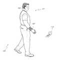
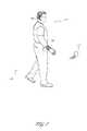
- FIG. 1shows a user wearing and carrying elements of a management and assistance system for the deaf.
- FIG. 2is a block diagram of various elements of the management and assistance system for the deaf.
- FIG. 3is a flowchart showing sound processing for external sounds.
- FIG. 4is a flowchart showing sound processing for speech generated by the user.
- FIG. 5shows the elements of a management and assistance system for the deaf in connection with a home automation system.
- FIG. 6Ais a diagram of a handheld device that can be used by the user or by a third party in connection with the assistance system for the deaf.
- FIG. 6Bis a block diagram of the handheld device shown in FIG. 6A .
- FIG. 7Ashows a vehicle sensor and warning system using forward and aft sensors and a cockpit display for helping deaf drivers.
- FIG. 7Bshows a vehicle sensor and warning system using four quadrant sensors and a cockpit display for helping deaf drivers.
- FIG. 8is a block diagram showing the vehicle system of FIGS. 7A and 7B .
- FIG. 1shows a user 101 wearing elements of a management and assistance system for the deaf.
- the user 101is shown wearing a communication module 102 and a headset 160 .
- a handheld module 112can be used by the user 101 or handed to a third party to aid in communication with the user 101 .
- the handheld module 112is used in lieu of the communication module 102 and provides the functions of the communication module 102 .
- the handheld moduleis complementary to the communication module 102 and used in connection with the communication module 102 .
- the disclosure that followsrefers to the communication module 102 , with the understanding that the communication module 102 can be built as a wearable device as shown in FIG. 1 or as a device that can be carried (e.g., handheld, carried in a pocket, etc.)
- the handheld module 112can be used by a deaf or hearing-impaired parent to monitor a child or children.
- the handheld module 112receives sounds from the child or the vicinity of the child and provides information to the communication module 102 .
- the handheld module 112can be placed in an area near the child or children.
- the handheld module 112can be configured to be worn by a child as a wearable device.
- the handheld module 112is configured to identify sounds corresponding to a child in trouble (e.g., crying, yelling, breaking glass, etc.) and warn the parent.
- the module 112includes a location sensor and is configured to identify a location of the child and warn the parent when the child has moved. In one embodiment, the module 112 is configured to warn the parent when the child has moved into a dangerous area (e.g., a forbidden room, a pool area, near a hot stove, etc.). In one embodiment, the module 112 can be queried by the communication module 102 so that the parent can “listen” in on the child by reading speech to text provided by the communication module 102 .
- a dangerous areae.g., a forbidden room, a pool area, near a hot stove, etc.
- the handheld module 112can also be used by a deaf or hearing-impaired person to monitor a being needing care and attention such as, for example, a spouse, a pet, an elderly parent, a disabled person, etc.
- One or more microphones in the headset 160provide acoustic information to the communication module 102 .
- the communication module 102uses the information from the microphones to ascertain the character of acoustic sounds in the environment, sounds made by the user 101 , and optionally, the direction of various sounds.
- the communication module 102uses the headset 160 to provide vibrator and/or optical alerts to the user 101 .
- the user 101can use a microphone in the headset 160 to send voice commands to the communication module 102 or 112 .
- the user 101can also use buttons on a keypad on the communication module 102 or 112 to control the operation of the system and input commands into the system.
- FIG. 2shows block diagrams of the headset 160 and a communication module 161 .
- the communication module 161is representative of the modules 102 and 112 shown in FIG. 1 .
- a first microphone 202In the headset 160 , a first microphone 202 , a vibrator 203 , a second microphone 204 , and a communication system 205 are provided to a processor 201 .
- the communication system 205can use Radio Frequency (RF) communication, optical (e.g., InfraRed communication), direct connection, etc.
- the first microphone 202is configured to pick up sounds in the environment (e.g., speech of others, sirens, horns, doorbells, etc.).
- the second microphone 204is configured to pick up the speech of the user 101 .
- the first and second microphones 202 , 204are configured to provide direction information so that the direction of a sound source can be ascertained.
- a microphone 251In the communication module 161 , a microphone 251 , a first communication system 256 , a keypad 253 , a display 254 , a vibrator 255 , and a second communication system 252 are provided to a processor 250 .
- the processor 250provides processing of the sounds received by the microphones 202 , 204 , and/or 251 .
- the acoustic signal processing algorithmsare used to distinguish danger sounds (e.g., sirens) from other sounds (e.g., the wind).
- the acoustic signal processing algorithmsare used to distinguish danger sounds (e.g., sirens) from indicator sounds (e.g., a doorbell).
- the acoustic signal processing algorithmsare used in speech recognition to convert the received sounds into text on the display 254 .
- a loudspeaker 257is provided to the module 161 .
- the user 101can enter text using the keypad 253 and instruct the processor 250 to convert the text to speech.
- FIG. 3is a flowchart showing one embodiment of processing of sounds from the environment (e.g., sounds not produced by the user 101 ).
- the systemreceives an external sound.
- an initial analysis of the soundis performed.
- the initial analysisis passed to a decision block 303 .
- the decision block 303determines if the external sound corresponds to voice sounds (e.g., talking, yelling, etc). If the sound is a voice sound, then control is passed to a speech analysis block 304 ; otherwise, control passes to a decision block 307 .
- the speech analysis block 304converts the sounds into text. Where the speaker's voice is recognized, the block 304 also identifies the speaker. If language translation has been requested, the block 304 also translates the text into a desired language.
- the results from the block 304are provided to a decision block 305 .
- the decision block 305determines if the speech corresponds to a warning (e.g., “watch out,” “stop”, etc.). If the sound is a warning sound, then control is passed to a classification block 308 ; otherwise, control passes to a display block 306 .
- the display block 306displays the text of the speech on the display 254 . In one embodiment, the display block 306 uses the vibrator to alert the user 101 to the presence of text.
- the decision block 307determines if the external sound corresponds to warning sounds (e.g., horns, sirens, etc). If the sound is a warning sound, then control is passed to the classification block 308 ; otherwise, control passes to a decision block 310 .
- the classification block 308classifies the urgency or potential level of danger indicated by the warning. Data from the classification block 308 is provided to a warning block 309 .
- the warning block 309uses the vibrators 203 , 255 , and the display 254 to alert and warn the user 101 . In one embodiment, the warning block 309 also uses the display to give the user an indication of the direction of the warning sound. In one embodiment, the strength of the vibrations produced by the vibrators 203 , 255 correspond to the relatively level of perceived danger.
- the decision block 310determines if the external sound corresponds to desired sounds (e.g., a doorbell, a beeper on a microwave oven, a ringing telephone, etc.). If the sound is a desired sound, then control is passed to a message block 311 ; otherwise, the sound is ignored and control returns to the block 301 .
- the message block 311classifies the type of sound and issues an appropriate message (e.g., “doorbell ringing, etc.).
- FIG. 4is a block diagram showing the processing for speech or sounds made by the user 101 .
- a block 401user speech sounds from the microphone on the headset 160 are received.
- the soundsare passed to a speech analysis block 402 .
- the block 402provides speech to text processing.
- the block 402also compares the volume of the speech to the ambient sounds.
- the results from the block 402are provided to a display block 403 .
- the display block 403displays the speech as text so that the user 101 can verify that his/her speech was intelligible and correctly formed.
- the display block 403also indicates the user's speech level as compared to the ambient level so that the user will know if he/she is speaking too loudly or too softly.
- the speech analysis block 402 and the display block 403provide displays to help the user 101 formulate speech sounds properly.
- most human languagesare composed of a relatively small number of sounds (e.g., the letters of the alphabet and the various ways of saying those letters.)
- the usercan place the system 160 in a mode where it will display such formants for the user so that the user can practice forming speech sounds in order to improve his/her speech.
- the user 101can carry an extra communication module 102 and provide the extra module 160 to a third person for conversation.
- the Third personcan speak into the second communication module 102 and see his/her speech converted to text on the display.
- the text on the third person's displayis relayed by the second communication module 102 to a first communication module 112 held or worn by the user 101 .
- both participants in the conversationcan verify that the speech to text operation and text-to-speech operations are translating speech and text as desired.
- FIG. 5Various elements of a communication and assistance system 100 for helping a deaf person 101 can be integrated into a home or building automation system 500 as shown in FIG. 5 .
- the elements shown in FIG. 5work together with the elements shown in FIG. 1 to provide additional functionality and capability.
- the system 500is described herein as a system to be used by a person who is deaf.
- the system 500includes a computer system 503 and/or communication module 502 to control the system 500 and, to collect data, and to provide data for the caretaker and/or the user 101 .
- the systemtypically includes a wireless communication module 112 and a wireless base unit 504 .
- the communication module 112communicates with the user 101 .
- the microphones placed about a house or structure 550provides an identification code to identify location, objects, environment, etc.
- the communication module 504reads the microphones and relays the information from the microphones to the computer 503 and/or to the user 101 .
- the system 500can also include one or more of the following optional devices: one or more video cameras monitors 505 , one or more loudspeakers 507 , one or more motion sensors 506 , etc.
- the system 500can further include one or more of the following optional devices: a remote control/display 112 for allowing the user 101 to interact with the system 503 , ambient condition sensors (e.g., smoke, gas, fire, etc.) etc.
- the ambient condition sensorsare wireless sensors that communicate wirelessly with the computer system 503 and/or communication module 112 .
- the system 500can be used as a computerized system for informing the user 101 of sounds or events around the house. Textual instructions or information can be provided through the 160 .
- a modem 530is provided for making connections with the telephone system, to allow the system 500 to communicate with a caretaker and/or the user 101 through cellular telephone, text messaging, pager, etc.
- a network connection 508e.g., an Internet connection, local area network connection, wide area network connection, etc.
- the caretaker and/or the user 101is provided to communicate with the system 500 and to allow the system 500 to receive updated software, updated status information, etc.
- the user 101can contact the system 503 to obtain map information, call for assistance, etc.
- the system 500provides indications (e.g., green light, text messages, etc.) when the user 101 is in a safe environment and/or warning indications (e.g., red lights, warning messages, vibration, etc.) when the user is in an unsafe environment (e.g., unknown person at the front door, motion sensor activated, smoke alarm activated, home security system activated, outside motion sensor activated, etc.).
- the user 101can select the conditions that trigger sounds versus vibrations.
- an experienced usermay choose to use vibration from the communicate module 112 for certain types of sounds and text messages for other types of sounds.
- the system 500uses the sensors 529 to detect fire or smoke.
- the system 500receives alarm data from a home alarm system.
- a wireless microphone 509is used to detect a fire alarm.
- the system 500can instruct the user to leave and notify the a family member or caretaker.
- the caretakercan be notified by using the loudspeakers 507 , by telephone, pager, and/or text messaging using the modem 530 to connect with the telephone system, and/or by using the network connection 508 (e.g., email instant messaging, etc.).
- the modem 530is configured to place a telephone call and then communicate with the user using data (e.g., in the case of text messaging) and/or synthesized voice.
- the modem 530can also be used by the caretaker and/or the user 101 to contact the computer system 503 and/or control the system 500 using voice recognition instructions and/or data or keyboard inputs from the cellular telephone.
- the communication device 160is configured with a cellular telephone interface so that the user 101 can communicate with the system 503 via the display and keyboard on the communication device 160 .
- the user's response to instructionsis monitored by the system 500 by using data from the communication module 102 , and/or by video processing from one or more video cameras 506 .
- the system 500can notify a neighbor, family member, or other caretaker.
- the user's response to instructionscan be determined by the caretaker and/or the user 101 in real time.
- a caretaker or instructorworks with the user 501 and the system 500 to get the user accustomed to the system.
- the communication module 102is configured to be carried and/or to be worn on the wrist, belt, chest, etc.
- the communication module 102includes one or more sound sensing devices (e.g., a microphones), a vibration device, and a communication device (e.g., a first RF transceiver).
- the sound sensing deviceis configured to sense sound waves (sonic and/or ultrasonic) such as, for example, a microphone, a transducer, etc.
- the sound sensing deviceis referred to herein as a microphone with the understanding that other acoustic transducers can be used as well.
- the sound producing deviceis referred to herein as a loudspeaker with the understanding that the sound producing device is configured to produce sound waves (sonic and/or ultrasonic) such as, for example, a loudspeaker, a transducer, a buzzer, etc.
- the communication module 102can also include one or more lights (not shown) for providing visual indications to the user.
- the microphonesare used to pick up sound waves such as, for example, sounds produced by the user 101 , sounds produced by other people, and/or acoustic waves produced by an acoustic location device (sonic or ultrasonic), etc.
- the microphone 202is configured to pick up external sounds (e.g., sounds not made by the user) and the microphone 204 is configured to pick up sounds made by the users.
- the system 100includes voice-recognition processing to help the user 101 know who is in the room, at door, etc., and what the person is saying.
- the processor 201processes the sounds picked up by the microphones and, if needed, sends processed data to the computer system 503 and/or communication module 102 for further processing.
- the vibratorcan be used in a manner similar to a vibrator on a cellular telephone to alert the user 101 without disturbing other people in the area.
- the vibratorcan also be used to alert the user 101 to abnormal or potentially dangerous conditions or to the presence of text messages on the communication device 160 . Deaf people tend to rely more on their sense of touch than people with good hearing.
- the vibratorcan be configured to provided different types of vibrations (e.g., different frequency, different intensity, different patterns, etc.) to send information to the user 101 .
- the first RF transceiver 205communicates with the communication unit 160 .
- the communication unit 160can communicate with the system 500 either directly or through the repeaters.
- the RF transceiver 205provides two-way communications such that the communication module 102 can send information to the computer system 503 and/or communication module 102 and receive instructions from the computer system 503 and/or communication module 102 .
- the computer system 503 and/or communication module 102 and the first RF transceiver 302communicate using a handshake protocol, to verify that data is received.
- the user 101can use the system 100 to “listen” to various microphones 509 around the house and thereby obtain information about the user's surroundings.
- microphonesare provided near windows, doors, in children's play areas, etc.
- the communication module 102includes one or more location and tracking systems, such as, for example, an IR system, a GPS location system, an Inertial Motion Unit (IMU) and/or radio frequency systems.
- the tracking systemscan be used alone or in combination to ascertain the location of the user 101 and to help the user 101 hear sounds in the areas about the structure 550 .
- a child's cry in a different roomcan be forwarded by the system 500 to the user 101 .
- a child's cry in a room occupied by the user 101does not need to be relayed because it will be picked up by the headset 160 .
- the microphone 204is used to allow the user to send voice commands to the system 500 .
- the communication module 102sends low-battery warnings to the computer system 503 and/or communication module 102 to alert the caretaker and/or the user 101 that the communication module 102 needs fresh batteries.
- GPSGlobal Positioning System
- GPS receiversalso require a certain amount of signal processing and such processing consumes power.
- the power consumed by a GPS systemcan reduce battery life.
- GPShas the advantages of being able to operate over a large area and is thus, particularly useful when locating a user that has escaped a confined area or is out of the range of other locating systems.
- the system 100uses GPS in outdoor situations where microphones are unavailable, and microphones indoors where GPS is unavailable or unreliable. Thus, using the system 100 , the position of the user 101 in a building can be ascertained.
- the GPS system 302operates in a standby mode and activates at regular intervals or when instructed to activate.
- the GPS systemcan be instructed by the computer 503 and/or to the user 101 or the communication module to activate.
- the GPS systemobtains a position fix on the user 101 (if GPS satellite signals are available) and updates the IMU.
- a GPS systemis also provided to the computer system 503 and/or communication module 102 .
- the computer systemuses data from its GPS system to send location and/or timing data to the GPS system in the communication module 102 allowing the GPS system 302 to warm start faster, obtain a fix more quickly, and therefore, use less power.
- location system unitsare placed about the house or building 550 to locate movement and location of the user 101 .
- location system unitssend infrared light, acoustic waves, and/or electromagnetic waves to one or more sensors on the communication module 102 in order to conserve power in the communication module 102 .
- the communication module 102sends infrared light, acoustic waves, and/or electromagnetic waves to the location system units in order to conserve power in the units.
- the communication module 102sends inaudible sounds (e.g., ultrasonic sounds) to the wireless microphones 509 to locate the user 101 .
- location system units placed near doorways or in hallwayscan be used to determine when the user 101 moves from one room to another. Even if the user cannot be exactly located within the room (e.g., due to blind spots), a location system unit placed to sense the movement of the user though the doorway allows the system 500 to know which room the user is in by watching the user 101 move from room to room.
- each location transmitter(whether in the communication module 102 or the location system units) sends a coded pattern of pulses to allow the transmitter to be identified.
- the location receiver(whether in the communication module 102 or the location system units 118 ) notifies the computer system 503 and/or communication module 102 whenever the pattern of received pulses changes.
- the location receiversends a “location sensor message” to the computer system 503 and/or communication module 102 .
- the location receiverdoes not send further location sensor messages so long as the location receiver continues to receive the pattern of pulses from the same location transmitter.
- the location receiversends location sensor messages to the computer system 103 and/or communication module 102 on a periodic basis so long as the location receiver continues to receive the pattern of pulses from the same transmitter.
- the location receiversends a “location sensor lost” message when the pattern of pulses stops.
- Motion detectors inside and/or outside a houseare commonly provided in connection with home security systems.
- the location system units 118are configured as motion detectors, and the IR system (e.g., transmitter and/or receiver) on the communication module 102 communicates with such IR motion detectors to avoid false alarms that would otherwise occur when the motion detector detects the movement of the user.
- the communication moduletransmits an IR signal that the motion detector recognizes as coming from the communication module 102 and thus, the motion detector knows that the motion it is sensing is due to the user and not an intruder.
- the communication module 102detects an IR transmission from a motion detector, the communication module transmits a response IR signal that the motion detector recognizes.
- the IR tracking system used by the system 500is also used as part of a home security system to track both the movement of the user and other movements in the house that are not due to the user.
- Acoustic motion detectors and/or microwave motion detectorscan be used with the communication module 102 similarly to the IR motion detectors.
- the sonic or ultrasonic location systemincludes a ranging function similar to that of an RF system.
- the ranging functionuses a two-frequency phase comparison system to measure distance from the sound transmitter to the sound receiver.
- the IR systemcan be used to send IR signals to the video cameras 506 .
- the system 500locates the user periodically (e.g., communicates with the communication module 102 ) and alerts the caretaker and/or the user 101 if the user cannot be found (e.g., if the system 100 cannot contact the communication module 102 ).
- the system 500can be used to communicate with the user.
- the system 500receives feedback regarding the user's speech patterns, actions, and can thus, learn various aspects of the user's behavior and vocabulary.
- the system 500is configured to adapt to the user's speech to warn the user when his/her speech is becoming unintelligible, too loud, too soft, etc.
- the system 100warns the user when the user is mispronouncing certain speech sounds.
- the user “speech recognition” systemcan base its discrimination on acoustic features, such as, for example, formant structure, pitch, loudness, spectral analysis, etc. When the computer recognizes the message behind the sounds made by the user, then the system 130 can respond accordingly.
- the system 500responds to voice commands, thus, for example, the user 101 can query the system 100 as to the outside temperature, set the home thermostat, turn lights on and off, etc.
- the system 503is provided with communications access (e.g., Internet access, cellular telephone access, pager access, etc.) to contact the caretaker.
- communications accesse.g., Internet access, cellular telephone access, pager access, etc.
- the system 503can contact a caretaker or emergency service.
- the system 500recognizes the speech of user 101 and family members, friends, etc. thus, if a stranger or unknown person enters the area and makes sounds, the system 500 can recognize that a stranger or unknown person is in the area and take appropriate action (e.g., notify the caretaker, emergency service, security service, etc.)
- FIG. 6is a block diagram of the handheld control 112 for the system 100 and.
- the remote control 112includes a microphone 604 , a loudspeaker 606 , a keyboard (or keypad) 612 , a display 613 , and a first RF transceiver 602 , all provided to a processor 601 .
- the remote control 112communicates with the computer system 503 and/or communication module 102 using the RF transceiver 602 to receive status information and to send instructions to the system 500 .
- the user 101can also use the remote control 112 to send instructions to the system 500 .
- the caretakercan speak to the user 101 .
- the communication module 102provides bi-directional communication and is configured to receive data and/or instructions from the base unit 504 .
- the base unit 504can instruct the communication module 102 to perform additional measurements, to go to a standby mode, to wake up, to report battery status, to change wake-up interval, to run self-diagnostics and report results, etc.
- the communication module 102reports its general health and status on a regular basis (e.g., results of self-diagnostics, battery health, etc.).
- the communication module 102samples, digitizes, and stores textual data from the microphone 204 when such data exceeds a volume threshold and/or when other sensors indicate that the textual data should be digitized and stored. For example, when sending voice commands, the user 101 can press a button on the keypad 253 to indicate that a voice command is being given. The user 101 can also use the keypad 253 to enter commands to the communication module 101 .
- the communication module 102provides two wake-up modes, a first wake-up mode for taking sensor measurements (and reporting such measurements if deemed necessary), and a second wake-up mode for listening for instructions from the central computer 103 and/or to the user 101 .
- the two wake-up modes, or combinations thereof,can occur at different intervals.
- the communication module 102use spread-spectrum techniques to communicate with the repeater unit 513 .
- the communication module 102uses Code Division Multiple Access (CDMA) techniques.
- the communication module 102uses frequency-hopping spread-spectrum.
- the communication module 102has an address or identification (ID) code that distinguishes the communication module 102 from the other RF units of the system 100 .
- the communication module 102attaches its ID to outgoing communication packets so that transmissions from the communication module 102 can be identified by the repeater 113 .
- the repeater 113attaches the ID of the communication module 102 to data and/or instructions that are transmitted to the communication module 102 .
- the communication module 102ignores data and/or instructions that are addressed to other RF units.
- the communication module 102includes a reset function.
- the reset functionis activated by a reset switch on the communication module 102 .
- the reset functionis activated when power is applied to the communication module 102 .
- the reset functionis activated when the communication module 102 is connected to the computer system 503 and/or communication module 102 by a wired connection for programming.
- the reset functionis active for a prescribed interval of time.
- the transceiveris in a receiving mode and can receive the identification code from the computer 503 and/or to the user 101 .
- the computer 503 and/or user 101wirelessly transmits a desired identification code.
- the identification codeis programmed by connecting the communication module 102 to the computer through an electrical connector, such as, for example, a USB connection, a firewire connection, etc.
- the electrical connection to the communication module 102is provided by sending modulated control signals (power line carrier signals) through a connector used to connect the power source 303 .
- the external programmerprovides power and control signals.
- the communication module 102communicates with the repeater 513 on the 900 MHz band. This band provides good transmission through walls and other obstacles normally found in and around a building structure. In one embodiment, the communication module 102 communicates with the repeater 513 on bands above and/or below the 900 MHz band. In one embodiment, the communication module 102 , repeater 513 , and/or base unit 504 listens to a radio frequency channel before transmitting on that channel or before beginning transmission. If the channel is in use, (e.g., by another device such as another repeater, a cordless telephone, etc.) then the sensor, repeater, and/or base unit changes to a different channel.
- the communication module 102coordinate frequency hopping by listening to radio frequency channels for interference and using an algorithm to select a next channel for transmission that avoids the interference.
- a dangerous conditione.g., a smoke alarm
- the communication module 102tests (e.g., listens to) the channel before transmission to avoid channels that are blocked, in use, or jammed.
- the communication module 102continues to transmit data until it receives an acknowledgement from the base unit 504 that the message has been received.
- the communication moduletransmits data having a normal priority (e.g., status information) and does not look for an acknowledgement, and the communication module transmits data having elevated priority until an acknowledgement is received.
- the repeater unit 513is configured to relay communications traffic between the communication module 102 and the base unit 504 .
- the repeater unit 513typically operates in an environment with several other repeater units.
- the repeater 513has an internal power source (e.g., battery, solar cell, fuel cell, etc.).
- the repeater 513is provided to household electric power.
- the repeater unit 513goes to a low-power mode when it is not transmitting or expecting to transmit.
- the repeater 513uses spread-spectrum techniques to communicate with the base unit 504 and with the communication module 102 .
- the repeater 113uses frequency-hopping spread-spectrum to communicate with the base unit 104 and the communication module 102 .
- the repeater unit 513has an address or identification (ID) code and the repeater unit 113 attaches its address to outgoing communication packets that originate in the repeater (that is, packets that are not being forwarded).
- IDaddress or identification
- the base unit 504communicates with the communication module 102 by transmitting a communication packet addressed to the communication module 102 .
- the repeaters 513receive the communication packet addressed to the communication module 102 .
- the repeaters 513transmit the communication packet addressed to the communication module 102 to the communication module 102 .
- the communication module unit 102 , the repeater units 513 , and the base unit 104communicate using Frequency-Hopping Spread Spectrum (FHSS), also known as channel-hopping.
- FHSSFrequency-Hopping Spread Spectrum
- Frequency-hopping wireless systemsoffer the advantages of avoiding other interfering signals and avoiding collisions. Moreover, there are regulatory advantages given to systems that do not transmit continuously at one frequency. Channel-hopping transmitters change frequencies after a period of continuous transmission, or when interference is encountered. These systems may have higher transmit power and relaxed limitations on in-band spurs.
- the computer 503maintains a database of the health, power status (e.g., battery charge), and current operating status of various units in the system 500 .
- the computer 503 and/or the user 101automatically performs routine maintenance by sending instructions to each unit to run a self-diagnostic and report the results.
- the computer 503 and/or the user 101collects and logs such diagnostic results.
- the computer 503 and/or the user 101sends instructions to tell each unit how long to wait between “wakeup” intervals.
- the computer 503 and/or the user 101schedules different wakeup intervals to different RF units based on the unit's health, power status, location, usage, etc.
- the computer 503 and/or the user 101schedules different wakeup intervals to different communication module units based on the type of data and urgency of the data collected by the unit.
- the computer 503 and/or to the user 101produces a display that tells the caretaker and/or the user 101 which RF units need repair or maintenance.
- the computer 503 and/or to the user 101maintains a list showing the status and/or location of each user 101 according to the ID of each communication module.
- each communication module 102has a unique identification code.
- the communication module 102 and /or the repeater units 513measure the signal strength of the wireless signals received (e.g., the communication module 102 measures the signal strength of the signals received from the repeater unit 513 , the repeater unit 513 measures the signal strength received from the communication module 102 and/or the base unit 504 ).
- the communication module 102 and/or the repeater units 513report such signal strength measurement back to the computer 503 and/or to the user 101 .
- the computer 503 and/or to the user 101evaluates the signal strength measurements to ascertain the health and robustness of the RF units of the system 500 .
- the computer 503 and/or to the user 101uses the signal strength information to re-route wireless communications traffic in the system 500 .
- the repeater unit 513goes offline or is having difficulty communicating with the communication module unit 160 , the computer 503 and/or to the user 101 can send instructions to a different repeater unit.
- the communication module 102includes radio frequency, acoustic and infrared communications capabilities.
- the system 100communicates with the communication module 102 using radio frequency, acoustic or infrared communication depending on the situation, e.g., acoustic, infrared, or relatively higher frequency radio frequencies for relatively shorter range communication and relatively lower frequency radio frequencies for relatively longer range communications.
- FIG. 7Ashows a vehicle sensor and warning system using forward and aft sensors and a cockpit display for helping deaf drivers.
- a vehicle 701is provided with a forward acoustic sensor system 703 and an aft acoustic sensor system 704 .
- the acoustics sensor systems 703 - 704provide acoustic information to a processing system 710 .
- the processing systemprovides information to a display 702 that provides warning and information to the driver.
- the display 702includes a warning light.
- the display 702includes a flashing light. In one embodiment, the display 702 includes a text display that provides text or picture information to the driver. In one embodiment, the display 702 indicates the type of sound (e.g., siren, screeching brakes, horn, impact or crash sounds, backup beeper sounds, sirens, warning shouts, etc.). In one embodiment, the display 702 indicates the direction of the sound. In one embodiment, the display 702 indicates the direction of the sound source. In one embodiment, the display 702 indicates the estimated distance to the sound. In one embodiment, the display 702 indicates the volume of the sound. In one embodiment, the display 702 indicates the duration the sound.
- the type of sounde.g., siren, screeching brakes, horn, impact or crash sounds, backup beeper sounds, sirens, warning shouts, etc.
- the display 702indicates the direction of the sound. In one embodiment, the display 702 indicates the direction of the sound source. In one embodiment, the display 702 indicates the estimated distance to the sound
- FIG. 7Bshows an alternative embodiment wherein four quadrant sensors 705 - 708 are provided to four quadrants of the vehicle.
- the sensors 703 - 708are wireless sensors that wirelessly provide information to the processor 710 . In one embodiment, the sensors 703 - 708 are wired sensors that are wired to the processor 710 . In one embodiment, the sensors 703 - 708 are microphones. In one embodiment, one or more of the sensors 703 - 708 are configured as an array of sensors in order to provide direction-finding information.
- one or more of the sensors 703 - 708are configured as a phased array of sensors in order to provide direction-finding information.
- the processor 710uses adaptive signal processing in connection with the phased array sensors to provide improved direction finding, beam steering, and noise reduction processing.
- the processor 710receives information from the sensors 703 - 704 and the signal processing in used by the processor includes digital beam forming, thereby allowing the processor 710 to calculate multiple beams and nulls from in the pattern of sound received by the sensors 703 - 704 .
- FIGS. 7A-7Bshow the sensors 703 - 708 mounted on the hood, trunk, or fender areas of the vehicle.
- the sensors 703 - 708can also be mounted on the roof, sides, front, and/or back of the vehicle.
- one or more of the sensors 703 - 708are provided to the lighting systems of the vehicle for mounting.
- FIG. 8is a block diagram showing the vehicle system of FIGS. 7A and 7B .
- the sensors 703 - 708are provided to the processor 710 .
- the processor 710processes acoustic information received by the sensors 703 - 708 and provides commands to the cockpit display 702 .
- an optional wireless interface 810is also provided to send information to the headset 160 and/or the communication module 102 to allow the headset 160 and/or communication module 102 to be used in connection with, or in lieu of, the cockpit display 702 .
Landscapes
- Engineering & Computer Science (AREA)
- Educational Administration (AREA)
- General Health & Medical Sciences (AREA)
- Business, Economics & Management (AREA)
- Physics & Mathematics (AREA)
- Audiology, Speech & Language Pathology (AREA)
- Health & Medical Sciences (AREA)
- Educational Technology (AREA)
- General Physics & Mathematics (AREA)
- Theoretical Computer Science (AREA)
- Alarm Systems (AREA)
- Percussion Or Vibration Massage (AREA)
- Emergency Alarm Devices (AREA)
- Mobile Radio Communication Systems (AREA)
Abstract
Description
Claims (29)
Priority Applications (11)
| Application Number | Priority Date | Filing Date | Title |
|---|---|---|---|
| US11/041,166US7356473B2 (en) | 2005-01-21 | 2005-01-21 | Management and assistance system for the deaf |
| EP05854890AEP1846907A1 (en) | 2005-01-21 | 2005-12-20 | Management and assistance system for the deaf |
| MX2007008766AMX2007008766A (en) | 2005-01-21 | 2005-12-21 | Management and assistance system for the deaf. |
| KR1020077018709AKR20070096028A (en) | 2005-01-21 | 2005-12-21 | Management and Assistance System for the Deaf |
| JP2007552138AJP2008529126A (en) | 2005-01-21 | 2005-12-21 | Management system and support system for the hearing impaired |
| PCT/US2005/046246WO2006078401A1 (en) | 2005-01-21 | 2005-12-21 | Management and assistance system for the deaf |
| RU2007131549/09ARU2007131549A (en) | 2005-01-21 | 2005-12-21 | MANAGEMENT AND ORIENTATION SYSTEM FOR THE DEAF |
| CA002595510ACA2595510A1 (en) | 2005-01-21 | 2005-12-21 | Management and assistance system for the deaf |
| AU2005325108AAU2005325108A1 (en) | 2005-01-21 | 2005-12-21 | Management and assistance system for the deaf |
| CNA2005800469723ACN101124617A (en) | 2005-01-21 | 2005-12-21 | Management and assistance system for the deaf |
| US12/022,086US20080120103A1 (en) | 2005-01-21 | 2008-01-29 | Management and assistance system for the deaf |
Applications Claiming Priority (1)
| Application Number | Priority Date | Filing Date | Title |
|---|---|---|---|
| US11/041,166US7356473B2 (en) | 2005-01-21 | 2005-01-21 | Management and assistance system for the deaf |
Related Child Applications (1)
| Application Number | Title | Priority Date | Filing Date |
|---|---|---|---|
| US12/022,086DivisionUS20080120103A1 (en) | 2005-01-21 | 2008-01-29 | Management and assistance system for the deaf |
Publications (2)
| Publication Number | Publication Date |
|---|---|
| US20060167687A1 US20060167687A1 (en) | 2006-07-27 |
| US7356473B2true US7356473B2 (en) | 2008-04-08 |
Family
ID=36005544
Family Applications (2)
| Application Number | Title | Priority Date | Filing Date |
|---|---|---|---|
| US11/041,166Expired - LifetimeUS7356473B2 (en) | 2005-01-21 | 2005-01-21 | Management and assistance system for the deaf |
| US12/022,086AbandonedUS20080120103A1 (en) | 2005-01-21 | 2008-01-29 | Management and assistance system for the deaf |
Family Applications After (1)
| Application Number | Title | Priority Date | Filing Date |
|---|---|---|---|
| US12/022,086AbandonedUS20080120103A1 (en) | 2005-01-21 | 2008-01-29 | Management and assistance system for the deaf |
Country Status (10)
| Country | Link |
|---|---|
| US (2) | US7356473B2 (en) |
| EP (1) | EP1846907A1 (en) |
| JP (1) | JP2008529126A (en) |
| KR (1) | KR20070096028A (en) |
| CN (1) | CN101124617A (en) |
| AU (1) | AU2005325108A1 (en) |
| CA (1) | CA2595510A1 (en) |
| MX (1) | MX2007008766A (en) |
| RU (1) | RU2007131549A (en) |
| WO (1) | WO2006078401A1 (en) |
Cited By (45)
| Publication number | Priority date | Publication date | Assignee | Title |
|---|---|---|---|---|
| US20060203295A1 (en)* | 2005-03-10 | 2006-09-14 | D Silva William T | Device, system and method for monitoring and interacting with a primary user |
| US20070046455A1 (en)* | 2005-09-01 | 2007-03-01 | Farley Daniel G | Fire alarm textual notification related application |
| US20080120103A1 (en)* | 2005-01-21 | 2008-05-22 | Lawrence Kates | Management and assistance system for the deaf |
| US20080172455A1 (en)* | 2007-01-12 | 2008-07-17 | Pixads, Llc | System for Providing Multimedia Content to Customers and Method Thereof |
| US20090237233A1 (en)* | 2008-03-19 | 2009-09-24 | United Parcel Service Of America, Inc. | Methods and systems for alerting persons of obstacles or approaching hazards |
| WO2011000113A1 (en)* | 2009-06-30 | 2011-01-06 | Harmonya Technologies | Multiple sound and voice detector for hearing- impaired or deaf person |
| US20110254703A1 (en)* | 2010-04-16 | 2011-10-20 | Empire Technology Development Llc | Pedestrian safety system |
| WO2011145117A2 (en) | 2010-05-17 | 2011-11-24 | Tata Consultancy Services Limited | Hand-held communication aid for individuals with auditory, speech and visual impairments |
| US9225527B1 (en) | 2014-08-29 | 2015-12-29 | Coban Technologies, Inc. | Hidden plug-in storage drive for data integrity |
| US9283138B1 (en) | 2014-10-24 | 2016-03-15 | Keith Rosenblum | Communication techniques and devices for massage therapy |
| US9307317B2 (en) | 2014-08-29 | 2016-04-05 | Coban Technologies, Inc. | Wireless programmable microphone apparatus and system for integrated surveillance system devices |
| USD768024S1 (en) | 2014-09-22 | 2016-10-04 | Toyota Motor Engineering & Manufacturing North America, Inc. | Necklace with a built in guidance device |
| US9578307B2 (en) | 2014-01-14 | 2017-02-21 | Toyota Motor Engineering & Manufacturing North America, Inc. | Smart necklace with stereo vision and onboard processing |
| US9576460B2 (en) | 2015-01-21 | 2017-02-21 | Toyota Motor Engineering & Manufacturing North America, Inc. | Wearable smart device for hazard detection and warning based on image and audio data |
| US9586318B2 (en) | 2015-02-27 | 2017-03-07 | Toyota Motor Engineering & Manufacturing North America, Inc. | Modular robot with smart device |
| US9629774B2 (en) | 2014-01-14 | 2017-04-25 | Toyota Motor Engineering & Manufacturing North America, Inc. | Smart necklace with stereo vision and onboard processing |
| US9677901B2 (en) | 2015-03-10 | 2017-06-13 | Toyota Motor Engineering & Manufacturing North America, Inc. | System and method for providing navigation instructions at optimal times |
| US9811752B2 (en) | 2015-03-10 | 2017-11-07 | Toyota Motor Engineering & Manufacturing North America, Inc. | Wearable smart device and method for redundant object identification |
| US9898039B2 (en) | 2015-08-03 | 2018-02-20 | Toyota Motor Engineering & Manufacturing North America, Inc. | Modular smart necklace |
| US9911309B1 (en) | 2017-01-17 | 2018-03-06 | Randal K. Kumagai | Personal proximity warning device which detects motion proximate a user |
| US9915545B2 (en) | 2014-01-14 | 2018-03-13 | Toyota Motor Engineering & Manufacturing North America, Inc. | Smart necklace with stereo vision and onboard processing |
| US9922236B2 (en) | 2014-09-17 | 2018-03-20 | Toyota Motor Engineering & Manufacturing North America, Inc. | Wearable eyeglasses for providing social and environmental awareness |
| US9934658B1 (en)* | 2016-09-14 | 2018-04-03 | Siemens Industry, Inc. | Visually-impaired-accessible building safety system |
| US9958275B2 (en) | 2016-05-31 | 2018-05-01 | Toyota Motor Engineering & Manufacturing North America, Inc. | System and method for wearable smart device communications |
| US9972216B2 (en) | 2015-03-20 | 2018-05-15 | Toyota Motor Engineering & Manufacturing North America, Inc. | System and method for storing and playback of information for blind users |
| US10012505B2 (en) | 2016-11-11 | 2018-07-03 | Toyota Motor Engineering & Manufacturing North America, Inc. | Wearable system for providing walking directions |
| US10024678B2 (en) | 2014-09-17 | 2018-07-17 | Toyota Motor Engineering & Manufacturing North America, Inc. | Wearable clip for providing social and environmental awareness |
| US10024679B2 (en) | 2014-01-14 | 2018-07-17 | Toyota Motor Engineering & Manufacturing North America, Inc. | Smart necklace with stereo vision and onboard processing |
| US10024667B2 (en)* | 2014-08-01 | 2018-07-17 | Toyota Motor Engineering & Manufacturing North America, Inc. | Wearable earpiece for providing social and environmental awareness |
| US10024680B2 (en) | 2016-03-11 | 2018-07-17 | Toyota Motor Engineering & Manufacturing North America, Inc. | Step based guidance system |
| US10045143B1 (en) | 2017-06-27 | 2018-08-07 | International Business Machines Corporation | Sound detection and identification |
| EP3123744B1 (en) | 2014-03-28 | 2018-11-14 | Bellman & Symfon Europe AB | Alerting system for deaf or hard of hearing people and application software to be implemented in an electronic device |
| US10152859B2 (en) | 2016-05-09 | 2018-12-11 | Coban Technologies, Inc. | Systems, apparatuses and methods for multiplexing and synchronizing audio recordings |
| US10165171B2 (en) | 2016-01-22 | 2018-12-25 | Coban Technologies, Inc. | Systems, apparatuses, and methods for controlling audiovisual apparatuses |
| US10172760B2 (en) | 2017-01-19 | 2019-01-08 | Jennifer Hendrix | Responsive route guidance and identification system |
| US10248856B2 (en) | 2014-01-14 | 2019-04-02 | Toyota Motor Engineering & Manufacturing North America, Inc. | Smart necklace with stereo vision and onboard processing |
| US10360907B2 (en) | 2014-01-14 | 2019-07-23 | Toyota Motor Engineering & Manufacturing North America, Inc. | Smart necklace with stereo vision and onboard processing |
| US10370102B2 (en) | 2016-05-09 | 2019-08-06 | Coban Technologies, Inc. | Systems, apparatuses and methods for unmanned aerial vehicle |
| US10432851B2 (en) | 2016-10-28 | 2019-10-01 | Toyota Motor Engineering & Manufacturing North America, Inc. | Wearable computing device for detecting photography |
| US10455342B2 (en) | 2013-06-05 | 2019-10-22 | Samsung Electronics Co., Ltd. | Sound event detecting apparatus and operation method thereof |
| US10490102B2 (en) | 2015-02-10 | 2019-11-26 | Toyota Motor Engineering & Manufacturing North America, Inc. | System and method for braille assistance |
| US10521669B2 (en) | 2016-11-14 | 2019-12-31 | Toyota Motor Engineering & Manufacturing North America, Inc. | System and method for providing guidance or feedback to a user |
| US10561519B2 (en) | 2016-07-20 | 2020-02-18 | Toyota Motor Engineering & Manufacturing North America, Inc. | Wearable computing device having a curved back to reduce pressure on vertebrae |
| US10789840B2 (en) | 2016-05-09 | 2020-09-29 | Coban Technologies, Inc. | Systems, apparatuses and methods for detecting driving behavior and triggering actions based on detected driving behavior |
| US10989427B2 (en) | 2017-12-20 | 2021-04-27 | Trane International Inc. | HVAC system including smart diagnostic capabilites |
Families Citing this family (74)
| Publication number | Priority date | Publication date | Assignee | Title |
|---|---|---|---|---|
| US7707035B2 (en)* | 2005-10-13 | 2010-04-27 | Integrated Wave Technologies, Inc. | Autonomous integrated headset and sound processing system for tactical applications |
| US7659814B2 (en)* | 2006-04-21 | 2010-02-09 | International Business Machines Corporation | Method for distributed sound collection and event triggering |
| WO2007147077A2 (en) | 2006-06-14 | 2007-12-21 | Personics Holdings Inc. | Earguard monitoring system |
| EP2044804A4 (en) | 2006-07-08 | 2013-12-18 | Personics Holdings Inc | PERSONAL HEARING AID AND METHOD |
| US20110156898A1 (en)* | 2006-12-08 | 2011-06-30 | Eric Taillefer | Environment sensing system for the hearing-impaired |
| US8917894B2 (en) | 2007-01-22 | 2014-12-23 | Personics Holdings, LLC. | Method and device for acute sound detection and reproduction |
| US11750965B2 (en) | 2007-03-07 | 2023-09-05 | Staton Techiya, Llc | Acoustic dampening compensation system |
| WO2008124786A2 (en) | 2007-04-09 | 2008-10-16 | Personics Holdings Inc. | Always on headwear recording system |
| US11217237B2 (en) | 2008-04-14 | 2022-01-04 | Staton Techiya, Llc | Method and device for voice operated control |
| US10194032B2 (en) | 2007-05-04 | 2019-01-29 | Staton Techiya, Llc | Method and apparatus for in-ear canal sound suppression |
| US11683643B2 (en) | 2007-05-04 | 2023-06-20 | Staton Techiya Llc | Method and device for in ear canal echo suppression |
| US11856375B2 (en) | 2007-05-04 | 2023-12-26 | Staton Techiya Llc | Method and device for in-ear echo suppression |
| DE102007025861A1 (en)* | 2007-06-01 | 2008-12-04 | Beine, Karlheinz, Dipl.-Ing. | Spoken language transforming device for use in office, has data processing unit including output device such as display e.g. LCD, for visually displaying text representation in real time, where display is formed in small lines |
| US20090010458A1 (en)* | 2007-07-06 | 2009-01-08 | Jts Professional Co., Ltd. | Wireless transmitter and microphone based communications system |
| US10009677B2 (en) | 2007-07-09 | 2018-06-26 | Staton Techiya, Llc | Methods and mechanisms for inflation |
| CN101241024B (en)* | 2008-02-29 | 2011-05-04 | 北京联合大学 | Sound triggering early-warning system |
| US8315876B2 (en)* | 2008-05-09 | 2012-11-20 | Plantronics, Inc. | Headset wearer identity authentication with voice print or speech recognition |
| US8600067B2 (en) | 2008-09-19 | 2013-12-03 | Personics Holdings Inc. | Acoustic sealing analysis system |
| US9129291B2 (en) | 2008-09-22 | 2015-09-08 | Personics Holdings, Llc | Personalized sound management and method |
| US20100088096A1 (en)* | 2008-10-02 | 2010-04-08 | Stephen John Parsons | Hand held speech recognition device |
| JP2011096130A (en)* | 2009-10-30 | 2011-05-12 | Toshiba Corp | Moving body proximity warning system for visually-challenged person accompanied by service dog, ultrasonic-wave generator for mounting on moving body used for the system, and ultrasonic-wave receiver used for the system |
| JP5723131B2 (en)* | 2010-10-01 | 2015-05-27 | 株式会社自立コム | Alarm method and device |
| US10045321B2 (en) | 2010-12-30 | 2018-08-07 | Staton Techiya, Llc | Information processing using a population of data acquisition devices |
| US12349097B2 (en) | 2010-12-30 | 2025-07-01 | St Famtech, Llc | Information processing using a population of data acquisition devices |
| US8761674B2 (en)* | 2011-02-25 | 2014-06-24 | Timothy R. Beevers | Electronic communication system that mimics natural range and orientation dependence |
| CN102323626A (en)* | 2011-05-23 | 2012-01-18 | 赵文琦 | Intelligent sensor |
| US10362381B2 (en) | 2011-06-01 | 2019-07-23 | Staton Techiya, Llc | Methods and devices for radio frequency (RF) mitigation proximate the ear |
| US20130070928A1 (en)* | 2011-09-21 | 2013-03-21 | Daniel P. W. Ellis | Methods, systems, and media for mobile audio event recognition |
| US9384272B2 (en) | 2011-10-05 | 2016-07-05 | The Trustees Of Columbia University In The City Of New York | Methods, systems, and media for identifying similar songs using jumpcodes |
| CN102499815B (en)* | 2011-10-28 | 2013-07-24 | 东北大学 | Method for assisting deaf people to perceive environmental sound |
| US8183997B1 (en)* | 2011-11-14 | 2012-05-22 | Google Inc. | Displaying sound indications on a wearable computing system |
| CN102637341A (en)* | 2012-04-20 | 2012-08-15 | 江苏奇异点网络有限公司 | Children monitoring system |
| JP2014066537A (en)* | 2012-09-25 | 2014-04-17 | Zenrin Datacom Co Ltd | Terminal device, route guidance method and computer program |
| KR102091003B1 (en) | 2012-12-10 | 2020-03-19 | 삼성전자 주식회사 | Method and apparatus for providing context aware service using speech recognition |
| US9756159B2 (en)* | 2013-02-14 | 2017-09-05 | New York University | Handphone |
| KR101394168B1 (en)* | 2013-02-20 | 2014-05-15 | 경희대학교 산학협력단 | A face information providing system and the face information providing service method for a hearing-impaired person |
| US20140257799A1 (en)* | 2013-03-08 | 2014-09-11 | Daniel Shepard | Shout mitigating communication device |
| TWI500023B (en)* | 2013-04-11 | 2015-09-11 | Univ Nat Central | Hearing assisting device through vision |
| US9280972B2 (en) | 2013-05-10 | 2016-03-08 | Microsoft Technology Licensing, Llc | Speech to text conversion |
| US9293135B2 (en)* | 2013-07-02 | 2016-03-22 | Volkswagen Ag | Countermeasures for voice recognition deterioration due to exterior noise from passing vehicles |
| US9167082B2 (en) | 2013-09-22 | 2015-10-20 | Steven Wayne Goldstein | Methods and systems for voice augmented caller ID / ring tone alias |
| WO2015046034A1 (en)* | 2013-09-30 | 2015-04-02 | 株式会社Jvcケンウッド | Voice volume notification device, data transmitter, data receiver, and voice volume notification system |
| KR101610443B1 (en)* | 2013-12-20 | 2016-04-20 | 현대자동차주식회사 | A driving assistance apparatus and a driving assistance method |
| US10043534B2 (en) | 2013-12-23 | 2018-08-07 | Staton Techiya, Llc | Method and device for spectral expansion for an audio signal |
| KR101598466B1 (en)* | 2014-07-08 | 2016-02-29 | 손석영 | safety assistance system for auditory disabled |
| KR101760013B1 (en)* | 2014-08-13 | 2017-07-31 | 엘지전자 주식회사 | Electronic device and method for controlling the same |
| CN106211009A (en)* | 2014-09-23 | 2016-12-07 | 博世汽车部件(苏州)有限公司 | Distinguish sound auxiliary device |
| EP3220372B1 (en)* | 2014-11-12 | 2019-10-16 | Fujitsu Limited | Wearable device, display control method, and display control program |
| CN104537926B (en)* | 2014-12-01 | 2017-11-14 | 上海交通大学 | Listen barrier childrenese training accessory system and method |
| KR101702612B1 (en)* | 2015-04-21 | 2017-02-13 | 손석영 | vehicle-safety assistance system for auditory disabled |
| US12268523B2 (en) | 2015-05-08 | 2025-04-08 | ST R&DTech LLC | Biometric, physiological or environmental monitoring using a closed chamber |
| BR112017027980A2 (en)* | 2015-06-26 | 2018-08-28 | Mandlakazi Zuko | alerting device, alerting system, alerting method, alerting system to remotely monitor and report a location of an object, and alerting method to remotely monitor and report a location of an object under surveillance |
| ES2607255B1 (en)* | 2015-09-29 | 2018-01-09 | Fusio D'arts Technology, S.L. | Notification method and device |
| KR101833030B1 (en) | 2015-10-26 | 2018-02-27 | 유퍼스트(주) | Method of providing alarm service for deaf and apparatus performing the same |
| US9978278B2 (en)* | 2015-11-27 | 2018-05-22 | Bragi GmbH | Vehicle to vehicle communications using ear pieces |
| US10616693B2 (en) | 2016-01-22 | 2020-04-07 | Staton Techiya Llc | System and method for efficiency among devices |
| CN106205292A (en)* | 2016-08-31 | 2016-12-07 | 北京青笋科技有限公司 | One listens barrier crowd to use Intelligent multifunctional electronic wrist-watch |
| EP3509549A4 (en)* | 2016-09-06 | 2020-04-01 | Neosensory, Inc. | METHOD AND SYSTEM FOR PROVIDING ADDITIONAL SENSORY INFORMATION TO A USER |
| GB2557594B (en) | 2016-12-09 | 2020-01-01 | Sony Interactive Entertainment Inc | Image processing system and method |
| WO2018107489A1 (en)* | 2016-12-16 | 2018-06-21 | 深圳前海达闼云端智能科技有限公司 | Method and apparatus for assisting people who have hearing and speech impairments and electronic device |
| KR101906549B1 (en)* | 2017-07-03 | 2018-10-12 | 유퍼스트(주) | A wearable device for hearing impairment person |
| CN107703735A (en)* | 2017-10-27 | 2018-02-16 | 苏州工艺美术职业技术学院 | Deaf-mute's wrist-watch |
| CN108852620A (en)* | 2018-01-19 | 2018-11-23 | 郭磊 | Intelligent neck wears equipment and its control method |
| US10817252B2 (en) | 2018-03-10 | 2020-10-27 | Staton Techiya, Llc | Earphone software and hardware |
| US10951994B2 (en) | 2018-04-04 | 2021-03-16 | Staton Techiya, Llc | Method to acquire preferred dynamic range function for speech enhancement |
| CN108831502A (en)* | 2018-05-04 | 2018-11-16 | 深圳市沃特沃德股份有限公司 | Caution sound identified off-line method and device |
| US11264029B2 (en) | 2019-01-05 | 2022-03-01 | Starkey Laboratories, Inc. | Local artificial intelligence assistant system with ear-wearable device |
| US11264035B2 (en)* | 2019-01-05 | 2022-03-01 | Starkey Laboratories, Inc. | Audio signal processing for automatic transcription using ear-wearable device |
| IT201900018077A1 (en)* | 2019-10-07 | 2021-04-07 | Business Service S R L | MANAGEMENT SYSTEM OF ANY ENVIRONMENT FOR THE BLIND |
| KR102328144B1 (en)* | 2019-12-03 | 2021-11-17 | 동의과학대학교산학협력단 | Multi-functional signal device for blind or hearing-impaired person |
| TWI743624B (en)* | 2019-12-16 | 2021-10-21 | 陳筱涵 | Attention assist system |
| JP7456326B2 (en)* | 2020-08-11 | 2024-03-27 | 株式会社Jvcケンウッド | Notification control device and notification system |
| GB2598333B (en)* | 2020-08-26 | 2023-09-20 | Advanced Risc Mach Ltd | A method and head-mounted unit for assisting a user |
| KR102633725B1 (en)* | 2022-01-12 | 2024-02-05 | 동의대학교 산학협력단 | Smart Glass System for the Hearing Impaired and Method for controlling the same |
Citations (20)
| Publication number | Priority date | Publication date | Assignee | Title |
|---|---|---|---|---|
| US4212085A (en)* | 1976-12-08 | 1980-07-08 | Mary C. Vaillancour | Frequency activated direction indicator |
| US4841773A (en)* | 1987-05-01 | 1989-06-27 | Litton Systems, Inc. | Miniature inertial measurement unit |
| US5173881A (en)* | 1991-03-19 | 1992-12-22 | Sindle Thomas J | Vehicular proximity sensing system |
| WO1993026084A1 (en) | 1992-06-05 | 1993-12-23 | Noise Cancellation Technologies, Inc. | Active plus selective headset |
| US5422816A (en)* | 1994-02-22 | 1995-06-06 | Trimble Navigation Limited | Portable personal navigation tracking system |
| US5495242A (en)* | 1993-08-16 | 1996-02-27 | C.A.P.S., Inc. | System and method for detection of aural signals |
| US5508699A (en) | 1994-10-25 | 1996-04-16 | Silverman; Hildy S. | Identifier/locator device for visually impaired |
| US5802460A (en)* | 1996-07-22 | 1998-09-01 | Sony Corporation | Telephone handset with remote controller for transferring information to a wireless messaging device |
| US5844824A (en)* | 1995-10-02 | 1998-12-01 | Xybernaut Corporation | Hands-free, portable computer and system |
| US5995936A (en)* | 1997-02-04 | 1999-11-30 | Brais; Louis | Report generation system and method for capturing prose, audio, and video by voice command and automatically linking sound and image to formatted text locations |
| WO2000000938A1 (en) | 1998-06-30 | 2000-01-06 | Tevfik Ercan | Home-communication system for people with hearing impairment |
| US6232918B1 (en)* | 1997-01-08 | 2001-05-15 | Us Wireless Corporation | Antenna array calibration in wireless communication systems |
| US6243075B1 (en)* | 1997-08-29 | 2001-06-05 | Xerox Corporation | Graspable device manipulation for controlling a computer display |
| US6404351B1 (en)* | 2000-10-20 | 2002-06-11 | Dennis Beinke | Emergency vehicle warning system |
| US6466232B1 (en)* | 1998-12-18 | 2002-10-15 | Tangis Corporation | Method and system for controlling presentation of information to a user based on the user's condition |
| US20030050040A1 (en)* | 2001-09-12 | 2003-03-13 | Nec Corporation | Emergency notification system and emergency notification device |
| US20030083024A1 (en)* | 2001-10-30 | 2003-05-01 | Lawrence Richenstein | Multiple channel wireless communication system |
| US20030179133A1 (en) | 2002-03-20 | 2003-09-25 | Gilles Pepin | Wireless handheld portabel navigation system and method for visually impaired pedestrians |
| US20030223455A1 (en) | 2002-05-29 | 2003-12-04 | Electronic Data Systems Corporation | Method and system for communication using a portable device |
| US20040145496A1 (en) | 1996-09-25 | 2004-07-29 | Ellis Christ G. | Intelligent vehicle apparatus and method for using the apparatus |
Family Cites Families (3)
| Publication number | Priority date | Publication date | Assignee | Title |
|---|---|---|---|---|
| US5808699A (en)* | 1995-10-02 | 1998-09-15 | Matsushita Electric Industrial Co., Ltd. | Visual image signal processing apparatus using arithmetic operation on brightness reference signal overlaid in fly-back period of input visual image signal |
| US5884824A (en)* | 1996-07-23 | 1999-03-23 | Spring, Jr.; Joseph N. | Equipment transport rack for vehicles providing improved loading accessibility |
| US7356473B2 (en)* | 2005-01-21 | 2008-04-08 | Lawrence Kates | Management and assistance system for the deaf |
- 2005
- 2005-01-21USUS11/041,166patent/US7356473B2/ennot_activeExpired - Lifetime
- 2005-12-20EPEP05854890Apatent/EP1846907A1/ennot_activeWithdrawn
- 2005-12-21MXMX2007008766Apatent/MX2007008766A/ennot_activeApplication Discontinuation
- 2005-12-21CACA002595510Apatent/CA2595510A1/ennot_activeAbandoned
- 2005-12-21CNCNA2005800469723Apatent/CN101124617A/enactivePending
- 2005-12-21KRKR1020077018709Apatent/KR20070096028A/ennot_activeCeased
- 2005-12-21JPJP2007552138Apatent/JP2008529126A/enactivePending
- 2005-12-21RURU2007131549/09Apatent/RU2007131549A/ennot_activeApplication Discontinuation
- 2005-12-21WOPCT/US2005/046246patent/WO2006078401A1/enactiveApplication Filing
- 2005-12-21AUAU2005325108Apatent/AU2005325108A1/ennot_activeAbandoned
- 2008
- 2008-01-29USUS12/022,086patent/US20080120103A1/ennot_activeAbandoned
Patent Citations (20)
| Publication number | Priority date | Publication date | Assignee | Title |
|---|---|---|---|---|
| US4212085A (en)* | 1976-12-08 | 1980-07-08 | Mary C. Vaillancour | Frequency activated direction indicator |
| US4841773A (en)* | 1987-05-01 | 1989-06-27 | Litton Systems, Inc. | Miniature inertial measurement unit |
| US5173881A (en)* | 1991-03-19 | 1992-12-22 | Sindle Thomas J | Vehicular proximity sensing system |
| WO1993026084A1 (en) | 1992-06-05 | 1993-12-23 | Noise Cancellation Technologies, Inc. | Active plus selective headset |
| US5495242A (en)* | 1993-08-16 | 1996-02-27 | C.A.P.S., Inc. | System and method for detection of aural signals |
| US5422816A (en)* | 1994-02-22 | 1995-06-06 | Trimble Navigation Limited | Portable personal navigation tracking system |
| US5508699A (en) | 1994-10-25 | 1996-04-16 | Silverman; Hildy S. | Identifier/locator device for visually impaired |
| US5844824A (en)* | 1995-10-02 | 1998-12-01 | Xybernaut Corporation | Hands-free, portable computer and system |
| US5802460A (en)* | 1996-07-22 | 1998-09-01 | Sony Corporation | Telephone handset with remote controller for transferring information to a wireless messaging device |
| US20040145496A1 (en) | 1996-09-25 | 2004-07-29 | Ellis Christ G. | Intelligent vehicle apparatus and method for using the apparatus |
| US6232918B1 (en)* | 1997-01-08 | 2001-05-15 | Us Wireless Corporation | Antenna array calibration in wireless communication systems |
| US5995936A (en)* | 1997-02-04 | 1999-11-30 | Brais; Louis | Report generation system and method for capturing prose, audio, and video by voice command and automatically linking sound and image to formatted text locations |
| US6243075B1 (en)* | 1997-08-29 | 2001-06-05 | Xerox Corporation | Graspable device manipulation for controlling a computer display |
| WO2000000938A1 (en) | 1998-06-30 | 2000-01-06 | Tevfik Ercan | Home-communication system for people with hearing impairment |
| US6466232B1 (en)* | 1998-12-18 | 2002-10-15 | Tangis Corporation | Method and system for controlling presentation of information to a user based on the user's condition |
| US6404351B1 (en)* | 2000-10-20 | 2002-06-11 | Dennis Beinke | Emergency vehicle warning system |
| US20030050040A1 (en)* | 2001-09-12 | 2003-03-13 | Nec Corporation | Emergency notification system and emergency notification device |
| US20030083024A1 (en)* | 2001-10-30 | 2003-05-01 | Lawrence Richenstein | Multiple channel wireless communication system |
| US20030179133A1 (en) | 2002-03-20 | 2003-09-25 | Gilles Pepin | Wireless handheld portabel navigation system and method for visually impaired pedestrians |
| US20030223455A1 (en) | 2002-05-29 | 2003-12-04 | Electronic Data Systems Corporation | Method and system for communication using a portable device |
Cited By (55)
| Publication number | Priority date | Publication date | Assignee | Title |
|---|---|---|---|---|
| US20080120103A1 (en)* | 2005-01-21 | 2008-05-22 | Lawrence Kates | Management and assistance system for the deaf |
| US20060203295A1 (en)* | 2005-03-10 | 2006-09-14 | D Silva William T | Device, system and method for monitoring and interacting with a primary user |
| US8319625B2 (en)* | 2005-09-01 | 2012-11-27 | Simplexgrinnell Lp | Fire alarm textual notification related application |
| US20070046455A1 (en)* | 2005-09-01 | 2007-03-01 | Farley Daniel G | Fire alarm textual notification related application |
| US20080172455A1 (en)* | 2007-01-12 | 2008-07-17 | Pixads, Llc | System for Providing Multimedia Content to Customers and Method Thereof |
| US20080172296A1 (en)* | 2007-01-12 | 2008-07-17 | Pixads, Llc | System for Providing Multimedia Content to Customers and Method Thereof |
| US20080172454A1 (en)* | 2007-01-12 | 2008-07-17 | Pixads, Llc | System for Providing Multimedia Content to Customers and Method Thereof |
| US20130106593A1 (en)* | 2008-03-19 | 2013-05-02 | United Parcel Service Of America, Inc. | Methods and systems for alerting persons of obstacles or approaching hazards |
| US8362896B2 (en)* | 2008-03-19 | 2013-01-29 | United Parcel Service Of America, Inc. | Methods and systems for alerting persons of obstacles or approaching hazards |
| US20090237233A1 (en)* | 2008-03-19 | 2009-09-24 | United Parcel Service Of America, Inc. | Methods and systems for alerting persons of obstacles or approaching hazards |
| US8633814B2 (en)* | 2008-03-19 | 2014-01-21 | United Parcel Service Of America, Inc. | Methods and systems for alerting persons of obstacles or approaching hazards |
| WO2011000113A1 (en)* | 2009-06-30 | 2011-01-06 | Harmonya Technologies | Multiple sound and voice detector for hearing- impaired or deaf person |
| US20110254703A1 (en)* | 2010-04-16 | 2011-10-20 | Empire Technology Development Llc | Pedestrian safety system |
| US8723691B2 (en)* | 2010-04-16 | 2014-05-13 | Empire Technology Development Llc | Pedestrian safety system |
| WO2011145117A2 (en) | 2010-05-17 | 2011-11-24 | Tata Consultancy Services Limited | Hand-held communication aid for individuals with auditory, speech and visual impairments |
| US10455342B2 (en) | 2013-06-05 | 2019-10-22 | Samsung Electronics Co., Ltd. | Sound event detecting apparatus and operation method thereof |
| US9915545B2 (en) | 2014-01-14 | 2018-03-13 | Toyota Motor Engineering & Manufacturing North America, Inc. | Smart necklace with stereo vision and onboard processing |
| US10360907B2 (en) | 2014-01-14 | 2019-07-23 | Toyota Motor Engineering & Manufacturing North America, Inc. | Smart necklace with stereo vision and onboard processing |
| US10248856B2 (en) | 2014-01-14 | 2019-04-02 | Toyota Motor Engineering & Manufacturing North America, Inc. | Smart necklace with stereo vision and onboard processing |
| US9578307B2 (en) | 2014-01-14 | 2017-02-21 | Toyota Motor Engineering & Manufacturing North America, Inc. | Smart necklace with stereo vision and onboard processing |
| US10024679B2 (en) | 2014-01-14 | 2018-07-17 | Toyota Motor Engineering & Manufacturing North America, Inc. | Smart necklace with stereo vision and onboard processing |
| US9629774B2 (en) | 2014-01-14 | 2017-04-25 | Toyota Motor Engineering & Manufacturing North America, Inc. | Smart necklace with stereo vision and onboard processing |
| EP3123744B1 (en) | 2014-03-28 | 2018-11-14 | Bellman & Symfon Europe AB | Alerting system for deaf or hard of hearing people and application software to be implemented in an electronic device |
| US10024667B2 (en)* | 2014-08-01 | 2018-07-17 | Toyota Motor Engineering & Manufacturing North America, Inc. | Wearable earpiece for providing social and environmental awareness |
| US9225527B1 (en) | 2014-08-29 | 2015-12-29 | Coban Technologies, Inc. | Hidden plug-in storage drive for data integrity |
| US9307317B2 (en) | 2014-08-29 | 2016-04-05 | Coban Technologies, Inc. | Wireless programmable microphone apparatus and system for integrated surveillance system devices |
| US10024678B2 (en) | 2014-09-17 | 2018-07-17 | Toyota Motor Engineering & Manufacturing North America, Inc. | Wearable clip for providing social and environmental awareness |
| US9922236B2 (en) | 2014-09-17 | 2018-03-20 | Toyota Motor Engineering & Manufacturing North America, Inc. | Wearable eyeglasses for providing social and environmental awareness |
| USD768024S1 (en) | 2014-09-22 | 2016-10-04 | Toyota Motor Engineering & Manufacturing North America, Inc. | Necklace with a built in guidance device |
| US9283138B1 (en) | 2014-10-24 | 2016-03-15 | Keith Rosenblum | Communication techniques and devices for massage therapy |
| US9576460B2 (en) | 2015-01-21 | 2017-02-21 | Toyota Motor Engineering & Manufacturing North America, Inc. | Wearable smart device for hazard detection and warning based on image and audio data |
| US10490102B2 (en) | 2015-02-10 | 2019-11-26 | Toyota Motor Engineering & Manufacturing North America, Inc. | System and method for braille assistance |
| US10391631B2 (en) | 2015-02-27 | 2019-08-27 | Toyota Motor Engineering & Manufacturing North America, Inc. | Modular robot with smart device |
| US9586318B2 (en) | 2015-02-27 | 2017-03-07 | Toyota Motor Engineering & Manufacturing North America, Inc. | Modular robot with smart device |
| US9811752B2 (en) | 2015-03-10 | 2017-11-07 | Toyota Motor Engineering & Manufacturing North America, Inc. | Wearable smart device and method for redundant object identification |
| US9677901B2 (en) | 2015-03-10 | 2017-06-13 | Toyota Motor Engineering & Manufacturing North America, Inc. | System and method for providing navigation instructions at optimal times |
| US9972216B2 (en) | 2015-03-20 | 2018-05-15 | Toyota Motor Engineering & Manufacturing North America, Inc. | System and method for storing and playback of information for blind users |
| US9898039B2 (en) | 2015-08-03 | 2018-02-20 | Toyota Motor Engineering & Manufacturing North America, Inc. | Modular smart necklace |
| US10165171B2 (en) | 2016-01-22 | 2018-12-25 | Coban Technologies, Inc. | Systems, apparatuses, and methods for controlling audiovisual apparatuses |
| US10024680B2 (en) | 2016-03-11 | 2018-07-17 | Toyota Motor Engineering & Manufacturing North America, Inc. | Step based guidance system |
| US10152859B2 (en) | 2016-05-09 | 2018-12-11 | Coban Technologies, Inc. | Systems, apparatuses and methods for multiplexing and synchronizing audio recordings |
| US10152858B2 (en) | 2016-05-09 | 2018-12-11 | Coban Technologies, Inc. | Systems, apparatuses and methods for triggering actions based on data capture and characterization |
| US10789840B2 (en) | 2016-05-09 | 2020-09-29 | Coban Technologies, Inc. | Systems, apparatuses and methods for detecting driving behavior and triggering actions based on detected driving behavior |
| US10370102B2 (en) | 2016-05-09 | 2019-08-06 | Coban Technologies, Inc. | Systems, apparatuses and methods for unmanned aerial vehicle |
| US9958275B2 (en) | 2016-05-31 | 2018-05-01 | Toyota Motor Engineering & Manufacturing North America, Inc. | System and method for wearable smart device communications |
| US10561519B2 (en) | 2016-07-20 | 2020-02-18 | Toyota Motor Engineering & Manufacturing North America, Inc. | Wearable computing device having a curved back to reduce pressure on vertebrae |
| US9934658B1 (en)* | 2016-09-14 | 2018-04-03 | Siemens Industry, Inc. | Visually-impaired-accessible building safety system |
| US10432851B2 (en) | 2016-10-28 | 2019-10-01 | Toyota Motor Engineering & Manufacturing North America, Inc. | Wearable computing device for detecting photography |
| US10012505B2 (en) | 2016-11-11 | 2018-07-03 | Toyota Motor Engineering & Manufacturing North America, Inc. | Wearable system for providing walking directions |
| US10521669B2 (en) | 2016-11-14 | 2019-12-31 | Toyota Motor Engineering & Manufacturing North America, Inc. | System and method for providing guidance or feedback to a user |
| US9911309B1 (en) | 2017-01-17 | 2018-03-06 | Randal K. Kumagai | Personal proximity warning device which detects motion proximate a user |
| US10172760B2 (en) | 2017-01-19 | 2019-01-08 | Jennifer Hendrix | Responsive route guidance and identification system |
| US10045143B1 (en) | 2017-06-27 | 2018-08-07 | International Business Machines Corporation | Sound detection and identification |
| US10989427B2 (en) | 2017-12-20 | 2021-04-27 | Trane International Inc. | HVAC system including smart diagnostic capabilites |
| US11708982B2 (en) | 2017-12-20 | 2023-07-25 | Trane International Inc. | HVAC system including smart diagnostic capabilities |
Also Published As
| Publication number | Publication date |
|---|---|
| RU2007131549A (en) | 2009-02-27 |
| AU2005325108A1 (en) | 2006-07-27 |
| MX2007008766A (en) | 2008-03-04 |
| CA2595510A1 (en) | 2006-07-27 |
| US20060167687A1 (en) | 2006-07-27 |
| WO2006078401A1 (en) | 2006-07-27 |
| CN101124617A (en) | 2008-02-13 |
| US20080120103A1 (en) | 2008-05-22 |
| JP2008529126A (en) | 2008-07-31 |
| WO2006078401A8 (en) | 2006-10-26 |
| EP1846907A1 (en) | 2007-10-24 |
| KR20070096028A (en) | 2007-10-01 |
Similar Documents
| Publication | Publication Date | Title |
|---|---|---|
| US7356473B2 (en) | Management and assistance system for the deaf | |
| CN107667394B (en) | Method for operating a self-propelled cleaning device | |
| US20060129308A1 (en) | Management and navigation system for the blind | |
| US12207171B2 (en) | Smart speakerphone emergency monitoring | |
| ES2971050T3 (en) | Notification method and device | |
| US20040155770A1 (en) | Audible alarm relay system | |
| US7839290B2 (en) | Sonic building rescue beacon | |
| US20190228628A1 (en) | Audio monitoring system | |
| KR101328865B1 (en) | Wrist watch for deaf and its control method | |
| KR101404717B1 (en) | the method and system safety management of preschooler | |
| JP2005309965A (en) | Home security device | |
| US20230381025A1 (en) | Situational awareness, communication, and safety in hearing protection and communication systems | |
| JP2007164474A (en) | Intrusion warning system | |
| CN110807896A (en) | Safety monitoring method, device and system | |
| CN119948543A (en) | Sensors and systems for monitoring | |
| KR20160125024A (en) | vehicle-safety assistance system for auditory disabled | |
| KR101598466B1 (en) | safety assistance system for auditory disabled | |
| US20230267815A1 (en) | Ear bud integration with property monitoring | |
| US20180350215A1 (en) | Multi-functional network camera control apparatus | |
| WO2019074457A2 (en) | Remotely assignable sensor group | |
| JP2006350595A (en) | Safety confirmation device | |
| JPH11120468A (en) | Life supporting device for aurally handicapped person | |
| JP2007019933A (en) | Mobile phone | |
| KR20210109940A (en) | Assistance system for the deaf using wearable device | |
| JP5474325B2 (en) | Surveillance dummy camera system |
Legal Events
| Date | Code | Title | Description |
|---|---|---|---|
| STCF | Information on status: patent grant | Free format text:PATENTED CASE | |
| CC | Certificate of correction | ||
| AS | Assignment | Owner name:KNOBBE, MARTENS, OLSON & BEAR, LLP, CALIFORNIA Free format text:SECURITY INTEREST;ASSIGNOR:KATES, LAWRENCE;REEL/FRAME:022460/0472 Effective date:20090121 Owner name:KNOBBE, MARTENS, OLSON & BEAR, LLP,CALIFORNIA Free format text:SECURITY INTEREST;ASSIGNOR:KATES, LAWRENCE;REEL/FRAME:022460/0472 Effective date:20090121 | |
| FEPP | Fee payment procedure | Free format text:PAYOR NUMBER ASSIGNED (ORIGINAL EVENT CODE: ASPN); ENTITY STATUS OF PATENT OWNER: LARGE ENTITY Free format text:PAYER NUMBER DE-ASSIGNED (ORIGINAL EVENT CODE: RMPN); ENTITY STATUS OF PATENT OWNER: LARGE ENTITY | |
| REMI | Maintenance fee reminder mailed | ||
| FPAY | Fee payment | Year of fee payment:4 | |
| SULP | Surcharge for late payment | ||
| AS | Assignment | Owner name:NEST LABS, INC., CALIFORNIA Free format text:ASSIGNMENT OF ASSIGNORS INTEREST;ASSIGNOR:KATES, LAWRENCE;REEL/FRAME:031658/0179 Effective date:20130927 Owner name:NEST LABS, INC., CALIFORNIA Free format text:RELEASE BY SECURED PARTY;ASSIGNOR:KNOBBE, MARTENS, OLSON & BEAR LLP;REEL/FRAME:031658/0093 Effective date:20130927 | |
| FEPP | Fee payment procedure | Free format text:PAT HOLDER NO LONGER CLAIMS SMALL ENTITY STATUS, ENTITY STATUS SET TO UNDISCOUNTED (ORIGINAL EVENT CODE: STOL); ENTITY STATUS OF PATENT OWNER: LARGE ENTITY | |
| AS | Assignment | Owner name:NEST LABS, INC., CALIFORNIA Free format text:CORRECTIVE ASSIGNMENT TO CORRECT THE INADVERTENT ADDITION OF U.S.PATENT NO. 8,101,892 TO THE LIST. ALL OTHER NUMBERS REMAIN AS PREVIOUSLY RECORDED ON REEL 031658 FRAME 0093. ASSIGNOR(S) HEREBY CONFIRMS THE U.S. PATENT NO. 8,101,892 IS TO BE REMOVED;ASSIGNOR:KNOBBE, MARTENS, OLSON & BEAR LLP;REEL/FRAME:033429/0848 Effective date:20130927 | |
| AS | Assignment | Owner name:NEST LABS, INC., CALIFORNIA Free format text:CORRECTIVE ASSIGNMENT TO CORRECT THE INADVERTENT PATENT NO. 8,101,892 TO BE REMOVED PREVIOUSLY RECORDED AT REEL: 031658 FRAME: 0179. ASSIGNOR(S) HEREBY CONFIRMS THE ASSIGNMENT;ASSIGNOR:KATES, LAWRENCE;REEL/FRAME:033452/0413 Effective date:20130927 | |
| AS | Assignment | Owner name:GOOGLE INC., CALIFORNIA Free format text:ASSIGNMENT OF ASSIGNORS INTEREST;ASSIGNOR:NEST LABS, INC.;REEL/FRAME:033568/0693 Effective date:20140207 | |
| FPAY | Fee payment | Year of fee payment:8 | |
| AS | Assignment | Owner name:GOOGLE LLC, CALIFORNIA Free format text:CHANGE OF NAME;ASSIGNOR:GOOGLE INC.;REEL/FRAME:044101/0610 Effective date:20170929 | |
| MAFP | Maintenance fee payment | Free format text:PAYMENT OF MAINTENANCE FEE, 12TH YEAR, LARGE ENTITY (ORIGINAL EVENT CODE: M1553); ENTITY STATUS OF PATENT OWNER: LARGE ENTITY Year of fee payment:12 |