US7355122B2 - Sealed eurytopic make-break connector utilizing a conductive elastomer contact - Google Patents
Sealed eurytopic make-break connector utilizing a conductive elastomer contactDownload PDFInfo
- Publication number
- US7355122B2 US7355122B2US11/395,443US39544306AUS7355122B2US 7355122 B2US7355122 B2US 7355122B2US 39544306 AUS39544306 AUS 39544306AUS 7355122 B2US7355122 B2US 7355122B2
- Authority
- US
- United States
- Prior art keywords
- contacts
- electrical
- conductive
- elastomeric material
- underwater
- Prior art date
- Legal status (The legal status is an assumption and is not a legal conclusion. Google has not performed a legal analysis and makes no representation as to the accuracy of the status listed.)
- Expired - Fee Related
Links
- 229920001971elastomerPolymers0.000titledescription12
- 239000000806elastomerSubstances0.000titledescription12
- 239000013536elastomeric materialSubstances0.000claimsabstractdescription32
- 239000002245particleSubstances0.000claimsabstractdescription19
- 239000000463materialSubstances0.000claimsabstractdescription12
- 239000004020conductorSubstances0.000claimsdescription19
- XLYOFNOQVPJJNP-UHFFFAOYSA-NwaterSubstancesOXLYOFNOQVPJJNP-UHFFFAOYSA-N0.000claimsdescription12
- 238000009413insulationMethods0.000claimsdescription6
- 239000011810insulating materialSubstances0.000claimsdescription4
- 239000004519greaseSubstances0.000claimsdescription3
- 229920001296polysiloxanePolymers0.000claimsdescription3
- 238000000034methodMethods0.000claims2
- 239000012212insulatorSubstances0.000claims1
- 230000008901benefitEffects0.000description5
- 150000003839saltsChemical class0.000description3
- RYGMFSIKBFXOCR-UHFFFAOYSA-NCopperChemical compound[Cu]RYGMFSIKBFXOCR-UHFFFAOYSA-N0.000description2
- 229910052802copperInorganic materials0.000description2
- 239000010949copperSubstances0.000description2
- 239000012530fluidSubstances0.000description2
- 230000013011matingEffects0.000description2
- 238000012986modificationMethods0.000description2
- 230000004048modificationEffects0.000description2
- 230000003647oxidationEffects0.000description2
- 238000007254oxidation reactionMethods0.000description2
- 229920002379silicone rubberPolymers0.000description2
- 239000004945silicone rubberSubstances0.000description2
- BQCADISMDOOEFD-UHFFFAOYSA-NSilverChemical compound[Ag]BQCADISMDOOEFD-UHFFFAOYSA-N0.000description1
- 230000005540biological transmissionEffects0.000description1
- 230000007797corrosionEffects0.000description1
- 238000005260corrosionMethods0.000description1
- 230000002708enhancing effectEffects0.000description1
- PCHJSUWPFVWCPO-UHFFFAOYSA-NgoldChemical compound[Au]PCHJSUWPFVWCPO-UHFFFAOYSA-N0.000description1
- 229910052737goldInorganic materials0.000description1
- 239000010931goldSubstances0.000description1
- 229930195733hydrocarbonNatural products0.000description1
- 150000002430hydrocarbonsChemical class0.000description1
- 239000007788liquidSubstances0.000description1
- 229920001084poly(chloroprene)Polymers0.000description1
- 239000011253protective coatingSubstances0.000description1
- 239000013535sea waterSubstances0.000description1
- 238000007789sealingMethods0.000description1
Images


Classifications
- E—FIXED CONSTRUCTIONS
- E21—EARTH OR ROCK DRILLING; MINING
- E21B—EARTH OR ROCK DRILLING; OBTAINING OIL, GAS, WATER, SOLUBLE OR MELTABLE MATERIALS OR A SLURRY OF MINERALS FROM WELLS
- E21B33/00—Sealing or packing boreholes or wells
- E21B33/02—Surface sealing or packing
- E21B33/03—Well heads; Setting-up thereof
- E21B33/035—Well heads; Setting-up thereof specially adapted for underwater installations
- E21B33/038—Connectors used on well heads, e.g. for connecting blow-out preventer and riser
- E21B33/0385—Connectors used on well heads, e.g. for connecting blow-out preventer and riser electrical connectors
- H—ELECTRICITY
- H01—ELECTRIC ELEMENTS
- H01R—ELECTRICALLY-CONDUCTIVE CONNECTIONS; STRUCTURAL ASSOCIATIONS OF A PLURALITY OF MUTUALLY-INSULATED ELECTRICAL CONNECTING ELEMENTS; COUPLING DEVICES; CURRENT COLLECTORS
- H01R13/00—Details of coupling devices of the kinds covered by groups H01R12/70 or H01R24/00 - H01R33/00
- H01R13/02—Contact members
- H01R13/22—Contacts for co-operating by abutting
- H01R13/24—Contacts for co-operating by abutting resilient; resiliently-mounted
- H01R13/2407—Contacts for co-operating by abutting resilient; resiliently-mounted characterized by the resilient means
- H01R13/2414—Contacts for co-operating by abutting resilient; resiliently-mounted characterized by the resilient means conductive elastomers
- H—ELECTRICITY
- H01—ELECTRIC ELEMENTS
- H01R—ELECTRICALLY-CONDUCTIVE CONNECTIONS; STRUCTURAL ASSOCIATIONS OF A PLURALITY OF MUTUALLY-INSULATED ELECTRICAL CONNECTING ELEMENTS; COUPLING DEVICES; CURRENT COLLECTORS
- H01R13/00—Details of coupling devices of the kinds covered by groups H01R12/70 or H01R24/00 - H01R33/00
- H01R13/46—Bases; Cases
- H01R13/52—Dustproof, splashproof, drip-proof, waterproof, or flameproof cases
- H01R13/523—Dustproof, splashproof, drip-proof, waterproof, or flameproof cases for use under water
Definitions
- the inventionis related to the field of electrical connectors and, more particularly, to eurytropic make-break connectors that can be used underwater and other wet environments, and in a wide variety of other environments.
- these electrical connectionstypically transmit electrical power from the surface to underwater equipment such as well heads or well control equipment.
- the connectionscan also transmit electrical signals from underwater equipment to the surface for processing.
- a commonly-used, wet, make-break connectorhas a plug and a receptacle that is open at two ends, with mating bands of copper extending axially along both parts. When the plug is stabbed into the receptacle, water will be pushed out the other end and the corresponding bands with contact each other to form an electrical connection.
- This type of connectorhas been found useful for low voltage and low current applications, but it is not practical for high voltage and high current usage.
- This type of connectoris also difficult to use because it cannot be connected unless the plug is properly oriented or aligned relative to the receptacle in order for the bands on the plug to mate with bands in the receptacle.
- This type of connectorcannot be used between a tubing hanger and an underwater wellhead, which require annular connector elements that do not have to have any specific orientation.
- the inventionsolves the problems discussed above with a eurytropic make-break electrical connection that has particular applicability underwater and other wet conditions, and in a wide variety of other environments.
- the term eurytropicrefers to the ability of the connection to work effectively in a wide variety of environments.
- the connectionhas first and second connectors that are adapted to engage each other to form an electrical connection.
- At least one of the connectorshas a conductor element or contact that is connected to an electrical wire and is formed of a conductive elastomeric material with conductive particles dispersed in the elastomeric material.
- the conductive elastomeric materialis shaped to deform when it engages the other contact and form an electrically conductive path between the connectors.
- Either one or both of the contactscan be formed of a conductive elastomeric material.
- An insulation layeris formed around the conductor elements, with a portion of the elastomeric material being exposed and adapted to engage the conductor on the other connector to form an electrical connection.
- the exposed portion of the elastomeric materialcan have a concave exposed end in order to more effectively squeeze water or moisture out from between the contacts.
- the contactcan be ring-shaped and mounted in a groove formed in a surrounding insulating material.
- the ring-shaped contactcan also have a plurality of alternating conductive and non-conductive regions spaced around the circumference of the ring.
- the contactscan be cylindrical in shape and have a convex exposed end that is adapted to mate with the other contact.
- connectioncan be used as an underwater electrical connector for a subsea wellhead or any other type of connector either above or below the water surface where a sealably connected device may be used.
- FIG. 1is a sectional view of an embodiment of the electrical connection of the present invention
- FIG. 2is a perspective with dotted lines showing internal elements of one embodiment of the connection in FIG. 1 , where the connection is cylindrical in shape;
- FIG. 3is a sectional view of the embodiment of the electrical connection in FIG. 1 , showing the connector elements being mounted in surrounding structural elements and being connected;
- FIG. 4is a plan view of one arrangement of multiple connectors of the type shown in FIG. 2 ;
- FIG. 5is a plan view another arrangement of multiple connectors of the type shown in FIG. 2 ;
- FIG. 6is a perspective view of another embodiment of the connection where the connectors are ring-shaped;
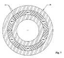
- FIG. 7is a plan view of the embodiment of the connector in FIG. 6 with alternating conducting and non-conducting portions;
- FIG. 8is an elevational view partially in section of an underwater wellhead in which the connection of the present invention can be used;
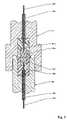
- FIG. 9is a sectional view of a ring-shaped embodiment of the connector of the invention, like the one shown in FIG. 6 , in an underwater wellhead;
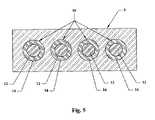
- FIG. 10is a sectional view of another embodiment of the invention where a pair of ring-shaped connectors are used.
- FIG. 11is an embodiment of a ring-shaped connector invention where one of the connectors has a contact formed of a conductive elastomer and the other contact does not.
- the inventionis directed to a eurytropic make-break electrical connection that has advantages for use underwater and in a wide variety of other environments including where the electrical contacts are exposed to wet conditions. Even though the invention is described in conjunction with underwater applications and, in particular, between a tubing hanger and an underwater wellhead, the connection can be used in any application where an electrical connection needs to be made up and taken apart or broken (i.e., a make-break connection).
- a dependable make-break connectionthat can be used underwater or in other environments, where moisture can be an issue, is formed in accordance with the invention by using one or more conductive elastomeric conductor elements or contacts.
- One conductive material that can be used for the contactsis a conductive silicone rubber material sold by the Chomerics Division of the Parker Hannifin Corp., Woburn, Mass. This material is formed of a silicone rubber that has clean, high structure, conductive particles such as silver powder dispersed throughout.
- High structurerefers to irregularly-shaped, sharp-cornered particles, which can be contrasted with relatively smooth and round particles that are referred to as having low structure. Particles formed of other types of conductive materials, such as copper or gold, could also be used. When the material is compressed, the particles move into closer contact with each other and form an enhanced electrically-conductive path within the contact material.
- An effective underwater, make-break electrical connectioncan be made by forming one or both of the contacts of such a conductive elastomer material. These contacts are shaped so that when they contact each other, at least one of them is compressed for enhancing the conductivity of the conductive particles inside the contact. When the material is deformed, the conductive particles dispersed throughout the material will move into closer contact with each other and form an enhanced electrically-conductive path in the contact for transmitting electric current from an electric wire in the contact to the other contact.
- An advantage of using a conductive elastomer as a contactis that neither element in an electrical connection has to be shaped in the form of a receptacle that receives the other one, which eliminates the need to remove moisture from the receptacle.
- Another advantage of this type of connectionis that it does not have any traps or seals that might cause a pressure imbalance when the seal is not made up, so all the exposed parts will have the same relative pressure at all times.
- An insulating layer in the form of a protective coating such as silicone greasemay be coated on the outer surface of the contact to isolate and prevent oxidation of portions of the conductive particles that are exposed to the atmosphere or water. When one or more of the contacts are compressed sharp edges of the conductive particles penetrate the silicone grease to complete the electrical connection by contacting the other contact.
- FIGS. 1 , 2 and 3One embodiment of a make-break electrical connection of the invention is shown in FIGS. 1 , 2 and 3 .
- the connectionincludes a pair of cylindrically-shaped connectors 10 a and 10 b , which includes conductor elements or contacts 12 a and 12 b , formed of a conductive elastomer mounted inside housings 14 a and 14 b , that are formed of a suitable insulating material such as neoprene rubber.
- the exposed portions of the contacts 12 a and 12 b , as well as adjacent portions of the housings 14 a and 14 bare preferably convex as shown in FIGS. 1-3 so that any moisture between them is squeezed out as they engage each other.
- Insulated electrical wires 16 a and 16 bare connected to the connectors 10 a and 10 b , respectively, with the insulation 18 a and 18 b of the wires being stripped off the wires 16 a and 16 b so that they are in electrical contact with the contacts 12 a and 12 b as shown.
- the connectors 10 a and 10 bcan be molded from appropriate materials as described above to form unitary connector configurations shown in FIGS. 1-3 .
- the connectors 10 a and 10 bcan be mounted in structural members such as those identified with reference letters A and B, as shown in FIG. 3 .
- the contact 12 acan be connected to an insulated electrical wire 16 a that is connected to a power or signal source (not shown).
- the other contact 12 bcan be connected to an insulated electrical wire 16 b that runs to an instrument, tool or other machine (not shown) that needs an electrical signal or power to operate.
- FIG. 3shows how the connection is made up.
- the adjacent contacts 12 a and 12 b , and housings 14 a and 14 bcompress and cause any water or moisture between them to squeezed out.
- the conductive particles in the conductive elastomerare compressed into greater contact with each other which, in turn, creates an enhanced conductive path for electrical current through the contacts 12 a and 12 b .
- a moisture-free electrical connectionis formed which is insulated from any surrounding structure.
- FIG. 11An example of such a connection is shown in FIG. 11 , which is described in greater detail below. Because of the compressibility of the conductive elastomer, an effective water-tight connection can be made with only one of the contacts compressing against an adjacent rigid contact and provide the same benefits.
- connectioncan be made up of a single pair of connectors as shown in FIGS. 1-3 , or the connection can include multiple connectors 10 , as shown in FIGS. 4 and 5 , when a number of electrical wires need to be connected.
- the multiple connectors 10can be arranged in any number of configurations such as, for example, in a line as shown in FIG. 4 or in a circle as shown in FIG. 5 .
- the connectors 10can include conductor elements 12 molded inside housings 14 that are mounted in a surrounding structure 5 .
- a mating structure(not shown) can be provided with the same configuration so that when the two structures are joined the connections can be completed.
- FIG. 5illustrates another embodiment where the connectors are arranged linearly in a structure 5 . With these types of connections, the connectors have to be aligned when they are joined so the conductor elements on opposite structures 5 can engage each other to provide closed electrical connections.
- the connectors 10can be ring-shaped as shown FIG. 6 .
- the ring-shaped contact 20is formed of a conductive elastomer that is positioned in a groove 22 in the insulated housing 24 as shown in FIGS. 6 , 9 , 10 and 11 .
- This shapeis preferable, for example, for connections between tubing hangers and underwater wellheads, shown in FIGS. 8 and 9 , as discussed in greater detail below, where the connections must be non-orienting, which means that the connections can be made up without having to radially align contacts on adjacent structures.
- the ring-shape contacts 20can be formed entirely of a conductive elastomer or, alternatively, as shown in FIG. 7 , the contact 12 can formed of alternating conductive and non-conductive segments 20 C and 20 N, respectively. If this contact is used in a radially orienting connection where the contact is aligned to mate with another contact of the same configuration, three conductive paths that are insulated from each other will be provided.
- connection of the inventioncan be used in an underwater wellhead 30 as illustrated in FIG. 8 .
- This type of high pressure wellheadprojects above the subsea surface or mudline 32 , and includes a conductor housing 34 .
- Flowlines 36 and 38are connected to the wellhead 30 for transporting produced hydrocarbons to the surface.
- the wellheadalso includes casing and tubing strings 40 and 42 , respectively, that are well known.
- FIG. 9shows a typical configuration inside the wellhead 30 where a tubing hanger 43 is designed to engage the conductor housing 34 .
- At least one electrical wire 48extends through a tubing hanger 43 for supplying power or signals to a downhole tool (not shown).
- the electrical wire 48is connected through a make-break connection that is made in accordance with the invention to another electrical wire 50 that extends through the wellhead 10 .
- the connection between the two linesmust be able to be made up or broken apart underwater because of the location of the underwater wellhead.
- FIG. 9shows the tubing hanger 43 in a position above the underwater wellhead 30 before the connectors 10 a and 10 b engage each other.
- the connectors 10 a and 10 bboth have ring-shaped contacts 12 a and 12 b as described above.
- the contacts 12 a and 12 bengage each other so that the contacts 12 a and 12 b will compress and complete an electrical connection between the electrical wires 48 and 50 .
- any water or other fluid between themwill be squeezed out.
- the contacts 12 a and 12 b for the electrical connection between the tubing hanger 43 and underwater wellhead 30are preferably ring-shaped as shown in FIG. 6 , and exte 5 d around the periphery of the wellhead 30 . In this way the connection is non-orienting, which as discussed above means that the contacts 12 a and 12 b , do not have to have any particular radial orientation in order to complete the electrical connections between them.
- two pairs of ring-shaped connectors 50 a and 50 b , and 52 a and 52 bcan be provided in order to provide electrical connections between a two pairs of electrical wires 54 a and 54 b , and 56 a and 56 b , respectively.
- a conduit 58should be provided in one of the surrounding structures 5 so that any fluid between the pairs of connectors can escape when the electrical connections are made up.
- FIG. 11shows a made up connection with two pairs of ring-shaped connectors 62 a and 62 b , and 64 a and 64 b , with the connectors 62 a and 64 a including contacts 66 a and 68 a , respectively, formed of a conductive elastomer as described above.
- the contacts 66 b and 68 bare formed of conventional conductors that are not compressible.
- the compressibility of only one of the contacts in each set of connectorsshould provide the connections with sufficient ability to squeeze moisture out from between the connections as the connectors engage each other and come together.
Landscapes
- Life Sciences & Earth Sciences (AREA)
- Engineering & Computer Science (AREA)
- Geology (AREA)
- Mining & Mineral Resources (AREA)
- Physics & Mathematics (AREA)
- Environmental & Geological Engineering (AREA)
- Fluid Mechanics (AREA)
- General Life Sciences & Earth Sciences (AREA)
- Geochemistry & Mineralogy (AREA)
- Connector Housings Or Holding Contact Members (AREA)
- Coupling Device And Connection With Printed Circuit (AREA)
Abstract
Description
Claims (32)
Priority Applications (2)
| Application Number | Priority Date | Filing Date | Title |
|---|---|---|---|
| US11/395,443US7355122B2 (en) | 2006-03-31 | 2006-03-31 | Sealed eurytopic make-break connector utilizing a conductive elastomer contact |
| PCT/US2007/065451WO2007115070A2 (en) | 2006-03-31 | 2007-03-28 | Sealed eurytopic make-break connector utilizing a conductive elastomer contact |
Applications Claiming Priority (1)
| Application Number | Priority Date | Filing Date | Title |
|---|---|---|---|
| US11/395,443US7355122B2 (en) | 2006-03-31 | 2006-03-31 | Sealed eurytopic make-break connector utilizing a conductive elastomer contact |
Publications (2)
| Publication Number | Publication Date |
|---|---|
| US20070227757A1 US20070227757A1 (en) | 2007-10-04 |
| US7355122B2true US7355122B2 (en) | 2008-04-08 |
Family
ID=38557161
Family Applications (1)
| Application Number | Title | Priority Date | Filing Date |
|---|---|---|---|
| US11/395,443Expired - Fee RelatedUS7355122B2 (en) | 2006-03-31 | 2006-03-31 | Sealed eurytopic make-break connector utilizing a conductive elastomer contact |
Country Status (2)
| Country | Link |
|---|---|
| US (1) | US7355122B2 (en) |
| WO (1) | WO2007115070A2 (en) |
Cited By (14)
| Publication number | Priority date | Publication date | Assignee | Title |
|---|---|---|---|---|
| US20090211761A1 (en)* | 2005-05-18 | 2009-08-27 | Argus Subsea, Inc. | Oil and gas well completion system and method of installation |
| US20100195853A1 (en)* | 2007-10-16 | 2010-08-05 | Estron A/S | Electrical Connector for a Hearing Device |
| US20110165793A1 (en)* | 2008-07-10 | 2011-07-07 | Gang Zhou | Waterproof Insulated Connector |
| US8198752B2 (en) | 2010-05-12 | 2012-06-12 | General Electric Company | Electrical coupling apparatus and method |
| US8441153B2 (en) | 2010-06-22 | 2013-05-14 | General Electric Company | Contactless power transfer system |
| US8518304B1 (en) | 2003-03-31 | 2013-08-27 | The Research Foundation Of State University Of New York | Nano-structure enhancements for anisotropic conductive material and thermal interposers |
| US8734175B2 (en)* | 2011-11-21 | 2014-05-27 | Sondex Wireline Limited | Flexible sealing connector |
| WO2014183115A1 (en)* | 2013-05-10 | 2014-11-13 | Baker Hughes Incorporated | Multiple use termination system |
| US20170149160A1 (en)* | 2015-11-25 | 2017-05-25 | Odu Gmbh & Co. Kg | Damping element for providing axial damping in a plug-in connector |
| US20170170590A1 (en)* | 2015-12-15 | 2017-06-15 | Samsung Electronics Co., Ltd. | Connector assembly |
| US9697951B2 (en) | 2012-08-29 | 2017-07-04 | General Electric Company | Contactless power transfer system |
| WO2021066971A1 (en)* | 2019-09-30 | 2021-04-08 | Halliburton Energy Services, Inc. | High pressure dual electrical collet assembly for oil and gas applications |
| US11189950B2 (en)* | 2016-04-12 | 2021-11-30 | HARTING Electronics GmbH | Plug connector with a conductive rubber element |
| US20220344871A1 (en)* | 2020-01-16 | 2022-10-27 | Pontus Subsea Connectors Llc | Pressure tolerant deep-sea electrical connector |
Families Citing this family (9)
| Publication number | Priority date | Publication date | Assignee | Title |
|---|---|---|---|---|
| FR2923953B1 (en)* | 2007-11-20 | 2010-02-26 | Schneider Electric Ind Sas | CONNECTION BAR WITH PLANE INTERFACE. |
| FR2945633A1 (en)* | 2009-05-18 | 2010-11-19 | Schneider Electric Ind Sas | SENSOR WITH FLAT INTERFACE AND ADAPTED CONNECTION |
| JP5714294B2 (en)* | 2010-10-25 | 2015-05-07 | 矢崎総業株式会社 | Connector structure for device connection |
| FR2972311B1 (en)* | 2011-03-01 | 2013-11-01 | Vam Drilling France | ANNULAR COUPLER FOR DRILL LINING COMPONENT |
| JP6031006B2 (en) | 2013-07-02 | 2016-11-24 | 矢崎総業株式会社 | Terminal fitting connection structure and rotation fitting type connector |
| JP6581620B2 (en)* | 2017-06-09 | 2019-09-25 | 矢崎総業株式会社 | Connector structure for device connection |
| DE102017131223B4 (en)* | 2017-12-22 | 2025-04-30 | Otto Bock Healthcare Products Gmbh | Plug system |
| US11121514B1 (en)* | 2018-09-17 | 2021-09-14 | Anritsu Company | Flange mount coaxial connector system |
| KR102338903B1 (en)* | 2021-03-29 | 2021-12-14 | (주)위드멤스 | Contactor and method for manufacturing the same |
Citations (14)
| Publication number | Priority date | Publication date | Assignee | Title |
|---|---|---|---|---|
| US3158420A (en)* | 1963-12-24 | 1964-11-24 | Le Roy O Olson | Underwater electrical connector |
| US3478298A (en)* | 1967-11-13 | 1969-11-11 | Electro Oceanics Inc | Fluidproof end connector |
| US3509296A (en)* | 1967-10-23 | 1970-04-28 | Ncr Co | Resilient variable-conductivity circuit controlling means |
| US3963133A (en)* | 1974-01-16 | 1976-06-15 | Societe Anonyme: Poclain | Public works machine having a removable counterweight and method of dismantling said counterweight |
| US4740657A (en)* | 1986-02-14 | 1988-04-26 | Hitachi, Chemical Company, Ltd | Anisotropic-electroconductive adhesive composition, method for connecting circuits using the same, and connected circuit structure thus obtained |
| US4797117A (en)* | 1982-12-23 | 1989-01-10 | Shell Oil Company | Marine electrical plug |
| US4943243A (en)* | 1988-10-21 | 1990-07-24 | Appleton Arthur I | Wire connector |
| US5120268A (en)* | 1990-08-07 | 1992-06-09 | Al Gerrans | Marine electrical connector |
| US5409403A (en)* | 1993-10-25 | 1995-04-25 | Falossi; Aldo | 360 degree connector system |
| US5823802A (en)* | 1997-07-30 | 1998-10-20 | General Motors Corporation | Electrical connector with combination seal and contact member |
| US6062872A (en)* | 1998-03-23 | 2000-05-16 | Thomas & Betts International, Inc. | High speed backplane connector |
| US6575764B1 (en)* | 1998-05-22 | 2003-06-10 | Reipur Technology A/S | Means for providing electrical contact |
| US6790057B2 (en)* | 2002-12-10 | 2004-09-14 | Tyco Electronics Corporation | Conductive elastomeric contact system with anti-overstress columns |
| US6929493B2 (en)* | 2003-05-06 | 2005-08-16 | Intelliserv, Inc. | Electrical contact for downhole drilling networks |
Family Cites Families (1)
| Publication number | Priority date | Publication date | Assignee | Title |
|---|---|---|---|---|
| FR2062051A5 (en)* | 1969-10-08 | 1971-06-25 | Inst Francais Du Petrole |
- 2006
- 2006-03-31USUS11/395,443patent/US7355122B2/ennot_activeExpired - Fee Related
- 2007
- 2007-03-28WOPCT/US2007/065451patent/WO2007115070A2/enactiveSearch and Examination
Patent Citations (14)
| Publication number | Priority date | Publication date | Assignee | Title |
|---|---|---|---|---|
| US3158420A (en)* | 1963-12-24 | 1964-11-24 | Le Roy O Olson | Underwater electrical connector |
| US3509296A (en)* | 1967-10-23 | 1970-04-28 | Ncr Co | Resilient variable-conductivity circuit controlling means |
| US3478298A (en)* | 1967-11-13 | 1969-11-11 | Electro Oceanics Inc | Fluidproof end connector |
| US3963133A (en)* | 1974-01-16 | 1976-06-15 | Societe Anonyme: Poclain | Public works machine having a removable counterweight and method of dismantling said counterweight |
| US4797117A (en)* | 1982-12-23 | 1989-01-10 | Shell Oil Company | Marine electrical plug |
| US4740657A (en)* | 1986-02-14 | 1988-04-26 | Hitachi, Chemical Company, Ltd | Anisotropic-electroconductive adhesive composition, method for connecting circuits using the same, and connected circuit structure thus obtained |
| US4943243A (en)* | 1988-10-21 | 1990-07-24 | Appleton Arthur I | Wire connector |
| US5120268A (en)* | 1990-08-07 | 1992-06-09 | Al Gerrans | Marine electrical connector |
| US5409403A (en)* | 1993-10-25 | 1995-04-25 | Falossi; Aldo | 360 degree connector system |
| US5823802A (en)* | 1997-07-30 | 1998-10-20 | General Motors Corporation | Electrical connector with combination seal and contact member |
| US6062872A (en)* | 1998-03-23 | 2000-05-16 | Thomas & Betts International, Inc. | High speed backplane connector |
| US6575764B1 (en)* | 1998-05-22 | 2003-06-10 | Reipur Technology A/S | Means for providing electrical contact |
| US6790057B2 (en)* | 2002-12-10 | 2004-09-14 | Tyco Electronics Corporation | Conductive elastomeric contact system with anti-overstress columns |
| US6929493B2 (en)* | 2003-05-06 | 2005-08-16 | Intelliserv, Inc. | Electrical contact for downhole drilling networks |
Cited By (28)
| Publication number | Priority date | Publication date | Assignee | Title |
|---|---|---|---|---|
| US8518304B1 (en) | 2003-03-31 | 2013-08-27 | The Research Foundation Of State University Of New York | Nano-structure enhancements for anisotropic conductive material and thermal interposers |
| US20090211761A1 (en)* | 2005-05-18 | 2009-08-27 | Argus Subsea, Inc. | Oil and gas well completion system and method of installation |
| US8286713B2 (en)* | 2005-05-18 | 2012-10-16 | Argus Subsea, Inc. | Oil and gas well completion system and method of installation |
| US20100195853A1 (en)* | 2007-10-16 | 2010-08-05 | Estron A/S | Electrical Connector for a Hearing Device |
| US20110165793A1 (en)* | 2008-07-10 | 2011-07-07 | Gang Zhou | Waterproof Insulated Connector |
| US8215975B2 (en) | 2008-07-10 | 2012-07-10 | Gang Zhou | Waterproof insulated connector |
| US8198752B2 (en) | 2010-05-12 | 2012-06-12 | General Electric Company | Electrical coupling apparatus and method |
| US8441153B2 (en) | 2010-06-22 | 2013-05-14 | General Electric Company | Contactless power transfer system |
| US8734175B2 (en)* | 2011-11-21 | 2014-05-27 | Sondex Wireline Limited | Flexible sealing connector |
| US9697951B2 (en) | 2012-08-29 | 2017-07-04 | General Electric Company | Contactless power transfer system |
| WO2014183115A1 (en)* | 2013-05-10 | 2014-11-13 | Baker Hughes Incorporated | Multiple use termination system |
| GB2529123A (en)* | 2013-05-10 | 2016-02-10 | Baker Hughes Inc | Multiple use termination system |
| US9458705B2 (en) | 2013-05-10 | 2016-10-04 | Baker Hughes Incorporated | Multiple use termination system |
| GB2529123B (en)* | 2013-05-10 | 2017-02-22 | Baker Hughes Inc | Multiple use termination system |
| US20170149160A1 (en)* | 2015-11-25 | 2017-05-25 | Odu Gmbh & Co. Kg | Damping element for providing axial damping in a plug-in connector |
| CN106961046B (en)* | 2015-11-25 | 2019-07-26 | 欧度有限责任两合公司 | For providing the damping element axially damped in plug-in connector |
| CN106961046A (en)* | 2015-11-25 | 2017-07-18 | 欧度有限责任两合公司 | Damping element for providing axially damping in plug-in connector |
| US9941617B2 (en)* | 2015-11-25 | 2018-04-10 | Odu Gmbh & Co. Kg | Damping element for providing axial damping in a plug-in connector |
| US20170170590A1 (en)* | 2015-12-15 | 2017-06-15 | Samsung Electronics Co., Ltd. | Connector assembly |
| US9966684B2 (en)* | 2015-12-15 | 2018-05-08 | Samsung Electronics Co., Ltd. | Connector assembly |
| US11189950B2 (en)* | 2016-04-12 | 2021-11-30 | HARTING Electronics GmbH | Plug connector with a conductive rubber element |
| WO2021066971A1 (en)* | 2019-09-30 | 2021-04-08 | Halliburton Energy Services, Inc. | High pressure dual electrical collet assembly for oil and gas applications |
| US11299937B2 (en) | 2019-09-30 | 2022-04-12 | Halliburton Energy Services, Inc. | High pressure dual electrical collet assembly for oil and gas applications |
| GB2601935A (en)* | 2019-09-30 | 2022-06-15 | Halliburton Energy Services Inc | High pressure dual electrical collet assembly for oil and gas applications |
| US11401751B2 (en) | 2019-09-30 | 2022-08-02 | Halliburton Energy Services, Inc. | High pressure electrical connector cable for oil and gas applications |
| GB2601935B (en)* | 2019-09-30 | 2023-09-13 | Halliburton Energy Services Inc | High pressure dual electrical collet assembly for oil and gas applications |
| US20220344871A1 (en)* | 2020-01-16 | 2022-10-27 | Pontus Subsea Connectors Llc | Pressure tolerant deep-sea electrical connector |
| US11677187B2 (en)* | 2020-01-16 | 2023-06-13 | Pontus Subsea Connectors Llc | Pressure tolerant deep-sea electrical connector |
Also Published As
| Publication number | Publication date |
|---|---|
| WO2007115070A3 (en) | 2008-10-02 |
| WO2007115070A2 (en) | 2007-10-11 |
| WO2007115070A8 (en) | 2008-01-03 |
| US20070227757A1 (en) | 2007-10-04 |
Similar Documents
| Publication | Publication Date | Title |
|---|---|---|
| US7355122B2 (en) | Sealed eurytopic make-break connector utilizing a conductive elastomer contact | |
| CA2651970C (en) | Apparatus and method for sealing an electrical connector | |
| US3879097A (en) | Electrical connectors for telemetering drill strings | |
| US7575458B2 (en) | Hi-dielectric debris seal for a pothead interface | |
| US7901240B2 (en) | Apparatus and method for electrical connector with flat cable adapter | |
| CA2651965C (en) | Apparatus and method for electrical and mechanical connection | |
| US5899765A (en) | Dual bladder connector | |
| EP2940242B1 (en) | Pressure-blocking feedthru | |
| GB9826630D0 (en) | Electrical connector system | |
| US20160276775A1 (en) | Wet Mate Connector | |
| US8491282B2 (en) | Pressure mitigating dielectric debris seal for a pothead interface | |
| US8215410B2 (en) | Apparatus and method for electrical packer feedthrough | |
| US5980317A (en) | Repairable electrical geophysical connector | |
| US4727223A (en) | Electrical penetrator | |
| CA2601553C (en) | Hi-dielectric debris seal for pothead interface | |
| US20070287318A1 (en) | Electrical connector and method of assembly | |
| US20220344871A1 (en) | Pressure tolerant deep-sea electrical connector | |
| WO2004032286A1 (en) | Connector assembly |
Legal Events
| Date | Code | Title | Description |
|---|---|---|---|
| AS | Assignment | Owner name:AZURA ENERGY SYSTEMS, INC., TEXAS Free format text:ASSIGNMENT OF ASSIGNORS INTEREST;ASSIGNOR:THE ESTATE OF BOYD B. MOORE (DECEASED), CHLOE MOORE, EXECUTOR;REEL/FRAME:019923/0423 Effective date:20071001 | |
| STCF | Information on status: patent grant | Free format text:PATENTED CASE | |
| AS | Assignment | Owner name:THE ROYAL BANK OF SCOTLAND PLC, UNITED KINGDOM Free format text:SECURITY AGREEMENT;ASSIGNOR:AZURA ENERGY SYSTEMS OFFSHORE, INC.;REEL/FRAME:022469/0318 Effective date:20080328 | |
| AS | Assignment | Owner name:THE ROYAL BANK OF SCOTLAND PLC,UNITED KINGDOM Free format text:AMENDED AND RESTATED PATENT SECURITY AGREEMENT SUPPLEMENT;ASSIGNOR:ARGUS SUBSEA INC.;REEL/FRAME:023882/0153 Effective date:20100115 Owner name:THE ROYAL BANK OF SCOTLAND PLC, UNITED KINGDOM Free format text:AMENDED AND RESTATED PATENT SECURITY AGREEMENT SUPPLEMENT;ASSIGNOR:ARGUS SUBSEA INC.;REEL/FRAME:023882/0153 Effective date:20100115 | |
| AS | Assignment | Owner name:HAYMARKET FINANCIAL LLP, AS SECURITY AGENT, UNITED Free format text:SECURITY AGREEMENT;ASSIGNOR:AZURA ENERGY SYSTEMS OFFSHORE, INC.;REEL/FRAME:026544/0827 Effective date:20110621 | |
| AS | Assignment | Owner name:ARGUS SUBSEA INC., TEXAS Free format text:RELEASE BY SECURED PARTY;ASSIGNOR:THE ROYAL BANK OF SCOTLAND PLC;REEL/FRAME:026573/0888 Effective date:20110621 | |
| FPAY | Fee payment | Year of fee payment:4 | |
| AS | Assignment | Owner name:HSBC CORPORATE TRUSTEE COMPANY (UK) LIMITED, UNITE Free format text:PATENT SECURITY AGREEMENT SUPPLEMENT DATED DECEMBER 8, 2012;ASSIGNORS:PROSERV OPERATIONS LLC;PROSERV HOLDINGS INC.;PROSERV OFFSHORE INC.;AND OTHERS;REEL/FRAME:029529/0937 Effective date:20121208 | |
| AS | Assignment | Owner name:AZURA ENERGY SYSTEMS, INC., TEXAS Free format text:RELEASE BY SECURED PARTY;ASSIGNOR:HAYMARKET FINANCIAL LLP, A SECURITY AGENT;REEL/FRAME:029586/0764 Effective date:20121213 Owner name:GILMORE VALVE COMPANY, TEXAS Free format text:RELEASE BY SECURED PARTY;ASSIGNOR:HAYMARKET FINANCIAL LLP, A SECURITY AGENT;REEL/FRAME:029586/0764 Effective date:20121213 Owner name:ARGUS SUBSEA INC., TEXAS Free format text:RELEASE BY SECURED PARTY;ASSIGNOR:HAYMARKET FINANCIAL LLP, A SECURITY AGENT;REEL/FRAME:029586/0764 Effective date:20121213 | |
| AS | Assignment | Owner name:PROSERV OFFSHORE, INC., TEXAS Free format text:MERGER;ASSIGNORS:ARGUS SUBSEA LLC;GILMORE VALVE COMPANY;PROSERV OFFSHORE, LLC;REEL/FRAME:030353/0458 Effective date:20130501 Owner name:PROSERV OPERATIONS, INC., TEXAS Free format text:MERGER;ASSIGNORS:GILMORE VALVE COMPANY;ARGUS SUBSEA LLC;PROSERV OFFSHORE LLC;REEL/FRAME:030353/0045 Effective date:20130501 | |
| AS | Assignment | Owner name:PROSERV OPERATIONS, LLC, TEXAS Free format text:TERMINATION AND RELEASE OF SECURITY INTEREST IN PATENTS;ASSIGNOR:HSBC CORPORATION TRUSTEE COMPANY (UK) LIMITED;REEL/FRAME:034810/0135 Effective date:20141223 Owner name:AZURA ENERGY SYSTEMS OFFSHORE, INC., TEXAS Free format text:TERMINATION AND RELEASE OF SECURITY INTEREST IN PATENTS;ASSIGNOR:HSBC CORPORATION TRUSTEE COMPANY (UK) LIMITED;REEL/FRAME:034810/0135 Effective date:20141223 Owner name:GILMORE VALVE COMPANY, TEXAS Free format text:TERMINATION AND RELEASE OF SECURITY INTEREST IN PATENTS;ASSIGNOR:HSBC CORPORATION TRUSTEE COMPANY (UK) LIMITED;REEL/FRAME:034810/0135 Effective date:20141223 Owner name:ARGUS SUBSEA INC., TEXAS Free format text:TERMINATION AND RELEASE OF SECURITY INTEREST IN PATENTS;ASSIGNOR:HSBC CORPORATION TRUSTEE COMPANY (UK) LIMITED;REEL/FRAME:034810/0135 Effective date:20141223 | |
| AS | Assignment | Owner name:PROSERV GROUP INC., TEXAS Free format text:RELEASE BY SECURED PARTY;ASSIGNOR:HSBC CORPORATE TRUSTEE COMPANY (UK) LIMITED AS SECURITY AGENT;REEL/FRAME:034839/0404 Effective date:20141223 Owner name:ARGUS SUBSEA INC., TEXAS Free format text:RELEASE BY SECURED PARTY;ASSIGNOR:HSBC CORPORATE TRUSTEE COMPANY (UK) LIMITED AS SECURITY AGENT;REEL/FRAME:034839/0404 Effective date:20141223 Owner name:GILMORE VALVE COMPANY, TEXAS Free format text:RELEASE BY SECURED PARTY;ASSIGNOR:HSBC CORPORATE TRUSTEE COMPANY (UK) LIMITED AS SECURITY AGENT;REEL/FRAME:034839/0404 Effective date:20141223 Owner name:AZURA ENERGY SYSTEMS OFFSHORE INC., TEXAS Free format text:RELEASE BY SECURED PARTY;ASSIGNOR:HSBC CORPORATE TRUSTEE COMPANY (UK) LIMITED AS SECURITY AGENT;REEL/FRAME:034839/0404 Effective date:20141223 | |
| AS | Assignment | Owner name:PROSERV OPERATIONS LLC, TEXAS Free format text:CHANGE OF NAME;ASSIGNOR:PROSERV OPERATIONS INC.;REEL/FRAME:035191/0562 Effective date:20130306 Owner name:PROSERV OPERATIONS INC., TEXAS Free format text:MERGER AND CHANGE OF NAME;ASSIGNORS:PROSERV EMPLOYING LLC;PROSERV OPERATIONS INC.;REEL/FRAME:035191/0683 Effective date:20130701 Owner name:AESI HOLDINGS, INC, MASSACHUSETTS Free format text:CHANGE OF NAME;ASSIGNOR:AZURA ENERGY SYSTEMS, INC.;REEL/FRAME:035222/0857 Effective date:20080306 Owner name:PROSERV EMPLOYING LLC, TEXAS Free format text:CHANGE OF NAME;ASSIGNOR:PROSERV OPERATIONS LLC;REEL/FRAME:035223/0091 Effective date:20130501 Owner name:PROSERV OPERATIONS INC., TEXAS Free format text:CHANGE OF NAME;ASSIGNOR:GALATHEA GROUP, INC.;REEL/FRAME:035222/0961 Effective date:20130306 Owner name:GALATHEA GROUP, INC., MASSACHUSETTS Free format text:CHANGE OF NAME;ASSIGNOR:AESI HOLDINGS, INC.;REEL/FRAME:035222/0854 Effective date:20090219 | |
| AS | Assignment | Owner name:HSBC BANK, NATIONAL ASSOCIATION, AS COLLATERAL AGE Free format text:SECURITY INTEREST;ASSIGNORS:PROSERV OPERATIONS INC.;PROSERV UK LIMITED;REEL/FRAME:035404/0208 Effective date:20150414 Owner name:UBS AG, STAMFORD BRANCH, AS COLLATERAL AGENT, CONN Free format text:SECURITY INTEREST;ASSIGNOR:PROSERV OPERATIONS INC.;REEL/FRAME:035404/0603 Effective date:20150414 | |
| FPAY | Fee payment | Year of fee payment:8 | |
| AS | Assignment | Owner name:PROSERV OPERATIONS, INC., TEXAS Free format text:TERMINATION AND RELEASE OF SECURITY INTEREST IN PATENT COLLATERAL;ASSIGNOR:HSBC BANK USA, NATIONAL ASSOCIATION;REEL/FRAME:045538/0279 Effective date:20180307 | |
| AS | Assignment | Owner name:RIVERSTONE V ACQUISITION HOLDINGS LTD., CAYMAN ISLANDS Free format text:ASSIGNMENT OF PATENT SECURITY AGREEMENT;ASSIGNOR:UBS AG, STAMFORD BRANCH;REEL/FRAME:045662/0200 Effective date:20180319 Owner name:RIVERSTONE V ACQUISITION HOLDINGS LTD., CAYMAN ISL Free format text:ASSIGNMENT OF PATENT SECURITY AGREEMENT;ASSIGNOR:UBS AG, STAMFORD BRANCH;REEL/FRAME:045662/0200 Effective date:20180319 | |
| AS | Assignment | Owner name:PROSERV OPERATIONS, INC., TEXAS Free format text:TERMINATION AND RELEASE OF SECURITY INTEREST IN PATENT COLLATERAL;ASSIGNOR:RIVERSTONE V ACQUISITION HOLDINGS LTD.;REEL/FRAME:045663/0904 Effective date:20180321 | |
| FEPP | Fee payment procedure | Free format text:MAINTENANCE FEE REMINDER MAILED (ORIGINAL EVENT CODE: REM.); ENTITY STATUS OF PATENT OWNER: SMALL ENTITY | |
| LAPS | Lapse for failure to pay maintenance fees | Free format text:PATENT EXPIRED FOR FAILURE TO PAY MAINTENANCE FEES (ORIGINAL EVENT CODE: EXP.); ENTITY STATUS OF PATENT OWNER: SMALL ENTITY | |
| STCH | Information on status: patent discontinuation | Free format text:PATENT EXPIRED DUE TO NONPAYMENT OF MAINTENANCE FEES UNDER 37 CFR 1.362 |