US7353996B2 - Device for storing and displaying selected bar codes - Google Patents
Device for storing and displaying selected bar codesDownload PDFInfo
- Publication number
- US7353996B2 US7353996B2US11/116,790US11679005AUS7353996B2US 7353996 B2US7353996 B2US 7353996B2US 11679005 AUS11679005 AUS 11679005AUS 7353996 B2US7353996 B2US 7353996B2
- Authority
- US
- United States
- Prior art keywords
- display
- codes
- code
- housing
- memory
- Prior art date
- Legal status (The legal status is an assumption and is not a legal conclusion. Google has not performed a legal analysis and makes no representation as to the accuracy of the status listed.)
- Expired - Lifetime, expires
Links
Images


Classifications
- G—PHYSICS
- G06—COMPUTING OR CALCULATING; COUNTING
- G06K—GRAPHICAL DATA READING; PRESENTATION OF DATA; RECORD CARRIERS; HANDLING RECORD CARRIERS
- G06K1/00—Methods or arrangements for marking the record carrier in digital fashion
- G06K1/12—Methods or arrangements for marking the record carrier in digital fashion otherwise than by punching
- G—PHYSICS
- G06—COMPUTING OR CALCULATING; COUNTING
- G06K—GRAPHICAL DATA READING; PRESENTATION OF DATA; RECORD CARRIERS; HANDLING RECORD CARRIERS
- G06K19/00—Record carriers for use with machines and with at least a part designed to carry digital markings
- G06K19/06—Record carriers for use with machines and with at least a part designed to carry digital markings characterised by the kind of the digital marking, e.g. shape, nature, code
- G06K19/067—Record carriers with conductive marks, printed circuits or semiconductor circuit elements, e.g. credit or identity cards also with resonating or responding marks without active components
- G06K19/07—Record carriers with conductive marks, printed circuits or semiconductor circuit elements, e.g. credit or identity cards also with resonating or responding marks without active components with integrated circuit chips
- G06K19/077—Constructional details, e.g. mounting of circuits in the carrier
- G06K19/07701—Constructional details, e.g. mounting of circuits in the carrier the record carrier comprising an interface suitable for human interaction
- G06K19/07703—Constructional details, e.g. mounting of circuits in the carrier the record carrier comprising an interface suitable for human interaction the interface being visual
- G—PHYSICS
- G06—COMPUTING OR CALCULATING; COUNTING
- G06K—GRAPHICAL DATA READING; PRESENTATION OF DATA; RECORD CARRIERS; HANDLING RECORD CARRIERS
- G06K7/00—Methods or arrangements for sensing record carriers, e.g. for reading patterns
- G06K7/10—Methods or arrangements for sensing record carriers, e.g. for reading patterns by electromagnetic radiation, e.g. optical sensing; by corpuscular radiation
- G06K7/10544—Methods or arrangements for sensing record carriers, e.g. for reading patterns by electromagnetic radiation, e.g. optical sensing; by corpuscular radiation by scanning of the records by radiation in the optical part of the electromagnetic spectrum
- G06K7/10821—Methods or arrangements for sensing record carriers, e.g. for reading patterns by electromagnetic radiation, e.g. optical sensing; by corpuscular radiation by scanning of the records by radiation in the optical part of the electromagnetic spectrum further details of bar or optical code scanning devices
- G06K7/1095—Methods or arrangements for sensing record carriers, e.g. for reading patterns by electromagnetic radiation, e.g. optical sensing; by corpuscular radiation by scanning of the records by radiation in the optical part of the electromagnetic spectrum further details of bar or optical code scanning devices the scanner comprising adaptations for scanning a record carrier that is displayed on a display-screen or the like
Definitions
- the present inventionrelates to display devices, and more particularly, this invention relates to a device that stores and displays bar codes and/or other optically-readable codes.
- Bar codeshave been used in a variety of applications for over a quarter of a century.
- a bar codeis an array of bars and spaces that represent numbers, letters, or other symbols, though the definition of bar code has been expanded to encompass two dimensional arrays of bars, dots and spaces.
- a bar code readeris used to read the code.
- the readeruses a laser beam and detector that is sensitive to the reflections from the line and space thickness and variations.
- the readertranslates the reflected light into digital data that is transferred to a computer for immediate action or storage.
- an LEDLight Emitting Diode
- line scanners, CCDs (Charge Coupled Devices), and camerasmay be used to read or scan bar code labels.
- Bar codes and readersare most often seen in supermarkets and retail stores, but are also used to take inventory in retail stores; to check out books from a library; to track manufacturing and shipping movement; to sign in on a job; to identify hospital patients; and to tabulate the results of direct mail marketing returns.
- a prevalent use of bar codes todayis in the field of consumer tracking, such as in grocery stores, and unique member identification numbers for clubs such as health clubs, video store memberships, library memberships, and frequent-purchase clubs and programs. Accordingly, each of these locations provides the customer with an individualized bar code identification card, which the customer must have present in order to access the facility, participate in activities therein, or receive particular benefits. Every program in which the customer participates increases the number of cards that the individual must carry to ensure entry into the health club or discount warehouse, to be able to check out books or videos, and to be eligible for the lowest prices at the supermarket or frequent-purchase program (such as at a bike store or vitamin store).
- Typical cardsare either credit-card size or a small “keychain”-tag size. While such cards are small and thin, just a few of the cards greatly increases the bulk of a wallet or purse.
- Carrying a multiplicity of cardsalso increases the amount of time the customer must spend at the check-out counter to find the correct card. Often these cards look similar, and time can be wasted if the customer presents the incorrect card. The customer may also be less inclined to join a frequent-purchase club or other type of club simply because they do not want to receive yet another membership card.
- What is neededis a single, portable device capable of replacing the plurality of cards that must currently be carried by the user. To that end, what is needed is a device for storing and displaying the appropriate bar code information at any location of the customer's choosing.
- the present descriptiondescribes a device that can store numerous optically readable codes (e.g., bar codes) for many purposes such as customer identification at or for: grocery stores, health clubs, frequent-purchase programs (bike store, vitamin store), library cards, video-store memberships, etc.
- optically readable codese.g., bar codes
- customer identificationat or for: grocery stores, health clubs, frequent-purchase programs (bike store, vitamin store), library cards, video-store memberships, etc.
- the devicein one embodiment contains a memory for storing the codes, a display for displaying the codes in sufficient contrast to be readable by an optical scanner, a selector for allowing the user to request display of the code(s), and a processor for coordinating operation of the memory, display and selector.
- the devices described hereinhave many permutations.
- One embodimentis not much larger than the keychain-tag size bar code tag, while another embodiment resembles a credit card.
- Other embodimentsimplement telephone and/or PDA (Personal Digital Assistant) functionality. Further embodiments display multiple codes simultaneously.
- PDAPersonal Digital Assistant
- FIG. 1is a simplified system diagram of a device for displaying optically readable codes according to one embodiment.
- FIG. 2is a partial cross sectional display of an electronic ink display.
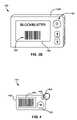
- FIGS. 3A-Bare perspective views of a device for displaying optically readable codes, the device having dimensions similar to a standard credit card.
- FIG. 4is a side view of a device for displaying optically readable codes, the device having dimensions similar to a keychain-size bar code tag.
- FIG. 5is a perspective view of a device for displaying optically readable codes embodied in a wireless telephone.
- FIG. 6is a perspective view of a device for displaying optically readable codes embodied in a PDA.
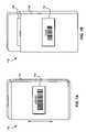
- FIGS. 7A-Bare perspective views of a device for displaying multiple optically readable codes, where the code is displayed through an aperture.
- FIG. 8is a simplified system diagram of a system implementing a device for displaying optically readable codes and an optical scanner.
- Optically readable codesas used herein are meant to encompass any code that is machine-readable via an optical scanner, including laser scanners and other scanners that use visible and/or invisible light to read a code.
- optically readable codesare referred to herein generally in terms of bar codes, though it should be kept in mind that any code readable by an optical scanning machine falls within the present definition of optically readable codes.
- Table 1summarizes the most common bar code standards, any of which may be implemented in the present invention.
- UPCBar Code Standard Typical Uses Uniform Product Code Retail stores for sales checkout; inventory, etc.
- Code 39 Identification, inventory, and tracking shipmentsCode 3 of 9
- POSTNETEncoding zip codes on U.S. mail European Article A superset of the UPC that allows extra digits for Number (EAN) country identification Japanese Article Similar to the EAN, used in Japan Number (JAN) Bookland Based on ISBN numbers and used on book covers ISSN bar code Based on ISSN numbers, used on periodicals outside the U.S.
- OCR-AThe optical character recognition format used on book covers for the human readable version of the ISBN number
- Maxicode Used by the United Parcel Service PDF417A new 2-D type of bar code that can encode up to 1108 bytes of information; can become a compressed, portable data file (PDF)
- the deviceis illustrated with a processor 102 , optional RAM (Random Access Memory) 103 , a read-only and/or rewritable nonvolatile memory 104 , device specific circuits 101 , and an I/O (Input/Output) interface 105 , any or all of which may comprise “elements” of the device 100 .
- the processor 102may be an off-the-shelf microprocessor, custom processor, programmable logic, discrete logic, ASIC (Application Specific Integrated Circuit), etc., as are known to those of skill in the art.
- the bar codesare preferably stored in the nonvolatile memory 104 .
- Thismay comprise a graphic representation of the bar codes, such as an image or picture.
- itmay comprise an encoded representation of the bar codes.
- the encoded bar code in nonvolatile memory 104may be converted by the device 100 to a suitable format for output to the display 108 .
- the nonvolatile memory 104may also hold the executable computer readable program code of a computer program product, or the logic of a programmable logic device, which may also be called firmware, and any nonvolatile data for the computer processor 102 , and may comprise a PROM (Programmable Read-Only Memory), flash PROM, EEPROM (Electrically Erasable PROM), MRAM (Magnetoresistive Random Access Memory), battery backup RAM (Random Access Memory), and other of many types of nonvolatile memory are also known to those of skill in the art.
- the processor 102may alternatively maintain the executable computer readable program code in an internal memory.
- the nonvolatile memory 104may also hold programmable firmware for a programmable logic processor 102 .
- An input/output interface 105may be provided, and is some form of communication mechanism that allows the computer processor 102 to communicate with and/or receive information from the outside world. Examples may include, but without limitation, SCSI (Small Computer Systems Interface), Ethernet, Fibre Channel interfaces, CAN (Controller Area Network), RS-232 (Recommended Standard), I2C (Inter-IC), USB (Universal Serial Bus), FireWire, etc. In addition, wireless communication mechanisms may also be used such as infrared, magnetic, inductive, RF etc. Alternatively or additionally, the input/output interface may comprise an access port at which an authorized person or apparatus may connect to the electronic device.
- the bar codescan be loaded into the system 100 through an input mechanism.
- the bar codesare loaded into nonvolatile memory 104 via the input/output interface 105 and a connection to an external computing device, such as a PC (Personal Computer), PDA (Personal Digital Assistant), wireless telephone, bar code scanner, system of the entity issuing the code, etc.
- an external computing devicesuch as a PC (Personal Computer), PDA (Personal Digital Assistant), wireless telephone, bar code scanner, system of the entity issuing the code, etc. Enabling the device 100 to connect to an external computing device allows the user to easily store all of the information in case the actual device 100 is broken, lost, or experiences a memory loss.
- the input/output interface 105may include a manual input mechanism such as a selector 109 (e.g., button(s), key(s), wheel, etc.) that receive user input.
- a selector 109e.g., button(s), key(s), wheel, etc.
- the bar codescan be loaded into the nonvolatile memory 104 via the selector 109 .
- the usercould enter the numerical equivalent of the bar code and device specific circuits 101 or software would convert the numerical equivalent into the appropriate bar code. This conversion could be done when the bar code numbers or letters are entered with the selector, or it could be done when the bar code is ready to be displayed on display 108 .
- the selector 109may also function to allow the user to select one or more bar codes for output on a display 108 .
- a button/key or wheelcan allow the user to sequentially scroll through the codes stored in the nonvolatile memory 104 .
- the selector 109can also initiate a sequence in which all of the codes, or subset thereof, stored in the nonvolatile memory 104 are sequentially displayed one or more times.
- the selector 109can even be as simple as an on/off button that starts the device 100 and begins cycling of the codes.
- the input mechanismmay comprise an optical scanner 113 that scans a bar code, which is then stored to nonvolatile memory 104 .
- the optical scanner 113can be external to the device 100 and connect thereto via a port, cable, or wirelessly.
- the device 100may be coupled to a personal computer through interface 105 .
- the personal computermay comprise a bar code scanner and the scanner may be used to read bar code labels for transfer to device 100 .
- the optical scanner 113can also be built in to the device 100 .
- the device 100may comprise an LED (Light Emitting Diode) and detector that may be used to read an existing bar code for storage into the nonvolatile memory 104 .
- the device 100may comprise a camera that takes a picture of the bar code label.
- the device 100may interpret the picture to determine the equivalent bar code, or it may store the picture in nonvolatile memory 104 . In the case of a stored picture, the device 100 may simply display the stored picture on display 108 when a user eventually selects the code for display.
- a number of devices and techniquesmay be used to capture or identify a representation of the bar code.
- any device that is used to read, photograph, copy, decode, or interpret a bar codecan be referred to and considered to be a scanner, optical scanner, and/or bar code scanner.
- other identification datamay also be input to indicate which bar code is associated with which business or club.
- wordscan be associated with the codes.
- the usercan enter the bar code and word on his or her PC and download that information to the device 100 , or scan the bar code information on the user's membership cards, credit cards or other similar type cards.
- bar codesmay temporarily be stored in RAM 103 or even not stored in memory but displayed on the display for a period of time or until the display is changed. For example, if the user is given a temporary membership to a club or gym, the bar code need only be stored for so long as needed, e.g., for the day. In another example, multiple bar codes may be displayed at the same time. In this case, there may not be a need for a selector or any kind of internal power source. To conserve storage space in the nonvolatile memory 104 , the bar code can be stored in RAM 103 and/or displayed on a persistent display (described below) for as long as the code is useful or active, until the RAM is rewritten, or until the display is changed.
- a persistent displaydescribed below
- the optional device specific circuits 101provide additional hardware to enable the device 100 to perform specific functions such as display bar codes, etc.
- the device specific circuits 101may comprise electronics that provide a display controller, etc.
- the device specific circuits 101may comprise electronics that provide the ability to scan a bar code or take a picture of a bar code.
- any of the elements of FIG. 1may be combined into one or more components, for example, the nonvolatile memory 104 , RAM 103 , and/or I/O interface 105 may comprise components of the processor 102 .
- the device 100is provided with a display 108 for displaying the bar codes in sufficient contrast to be detectable by an optical scanner such as a laser scanner. Because the bar codes need only be displayed when the user presents the device, the display can be activated upon user-actuation of an input mechanism (selector, button(s), key(s), wheel, on/off switch, etc.). Essentially, the device 100 wakes from an “off” state or a low power “sleep” mode entered into after a short period of time has elapsed.
- an input mechanismswitch, button(s), key(s), wheel, on/off switch, etc.
- the electronic display 108can be an LCD (Liquid Crystal Display), LED (Light Emitting Diode) display, or equivalent, as understood by those of skill in the art.
- Examples of power sources for such displays (and overall system)may comprise a battery, a capacitor, electrical connection, electromagnetic induction, light, RF energy, etc., as is understood by those of skill in the art.
- the displaycomprises at least one electronic module for operating the display 108 .
- the electronic modulecomprises an input for providing a signal for updating the display 108 .
- a power elementcan be provided to update and maintain the display.
- the display 108is preferably an electronic persistent visual display mounted to the device 100 .
- the persistent visual displayis defined as providing a visual display which persists indefinitely, even if any input signal is removed. Thus, an input signal may update the display, and the updated display will persist after the input signal is removed.
- An electronic persistent visual display 108has a stable image “memory effect” for an extended period of time.
- An example of an electronic persistent visual display which has a persistent display in the absence of poweris an electronic ink, or “E Ink”, electronic display which is available from E Ink Corporation, 733 Concord Ave., Cambridge, Mass. 02138 (www.eink.com).
- FIG. 2depicts a portion of an illustrative electronic ink display 200 according to one embodiment.
- each microcapsule 202contains positively charged white particles 204 and negatively charged black particles 206 suspended in a clear fluid 208 .
- a negative electric fieldis applied to a top (outer) substantially transparent electrode 210 , the white particles 204 move to the top of the microcapsule 202 where they become visible to the user. This makes the surface appear white at that spot.
- an opposite electric field at a bottom electrode 212pulls the black particles 206 to the bottom of the microcapsules 202 where they are hidden. By reversing this process, the black particles 206 appear at the top of the microcapsule 202 , which now makes the surface appear dark at that spot. Note that subcapsule addressing, as shown in the microcapsule 202 on the right side of FIG. 2 , enables high resolution display capabilities.
- the inkis printed onto a sheet of plastic film that is laminated to a layer of circuitry including the electrodes 210 .
- the circuitryforms a pattern of pixels that can then be controlled by a display driver.
- These microcapsulesare suspended in a liquid “carrier medium” allowing them to be printed using existing screen printing processes onto virtually any surface, including glass, plastic, fabric and even paper.
- Electronic inkhas a much higher contrast ratio than LCD displays. Further, electronic ink displays are completely reflective requiring no backlight, and they have an inherently image stable “memory effect” for extended periods of time requiring no power between image states. Once an image is written on an electronic ink display, it will be retained without additional power input until the next image is written. Hence the power consumption of an electronic ink display will ultimately depend upon the frequency at which the displayed image is changed and not how long a display is read.
- the processor 102coordinates operation of the memory 103 , 104 , display 108 , input/output interface 105 , and may operate the operational element 101 .
- the processorin response to a request to display one or more bar codes, provides an update input signal at the display input of FIG. 1 .
- the update input signalcomprises information selected from the information regarding the electronic device stored in the nonvolatile memory 104 , and/or stored by the processor 102 .
- the update signalupdates the output of the display 108 .
- FIGS. 3A-Bdepicts illustrative devices 100 having a compact housing 300 .
- the devices 100are about the size of a standard credit card, e.g., having dimensions of less than about 3.50 inches long (L) by less than about 2.50 inches wide (W) by less than about 0.250 inches thick (T) (though the thickness is preferably smaller than 0.125 inches).
- L3.50 inches long
- W2.50 inches wide
- T0.250 inches thick
- These embodimentscould be placed in the user's wallet or purse along with credit cards, etc.
- electronic ink displaysare durable and flexible, slight bending of the devices 100 will not cause any damage to the devices 100 .
- the device 100 of FIG. 3Ais shown with a large display 108 and a wheel type selector 109 .
- a wheel type selector 109may be preferred in certain embodiments, as it is less likely to be actuated unintentionally in a wallet or purse, as compared to buttons.
- key type selectors 109can be used alternatively, as shown in FIG. 3B . Or a combination of keys and wheel can be used.
- the useractuates the selector 109 (rolls the wheel or presses the keys) to sequentially scroll through the bar codes stored in memory.
- the desired bar code 302is displayed, in this case, the bar code associated with the user's BLOCKBUSTER® account, the user, or other person, then positions the display 108 over an optical scanner.
- the optical scannerreads the bar code 302 from the display 108 as if the device were the original membership card issued by Blockbuster.
- FIG. 4depicts a device 100 which has dimensions similar to a keychain-size bar code tag, e.g., less than about 2.25 inches long by less than about 1.00 inch wide by less than about 0.250 inches thick (though the thickness is preferably smaller than 0.125 inches).
- This embodimentfeatures an aperture 402 through the housing 400 for receiving a key ring 404 or keychain.
- the selector 109 in this exemplary embodimentis a button that, upon each actuation, displays one of the stored bar codes.
- the selector 109can also be programmed to sequentially cycle through all of the codes stored in memory upon actuation. The likelihood of each of the issuing entities (grocery store, vitamin club, etc.) using identical-length bar codes and/or identical account names and numbers for personal identification is low, so automatically cycling through the bar codes would simplify functionality.
- FIG. 5depicts a variation in which the device 100 is embodied in a wireless telephone.
- the device 100is embodied in a wireless telephone.
- One skilled in the artwill appreciate how a wireless telephone functions and is constructed.
- the selector 109includes the keys 402 .
- keystrokesthat can be used to retrieve the bar codes. For instance, pressing an up key or down key can allow the user to scroll through the stored bar codes in the form of a memory catalog (like the catalog of phone numbers for a wireless phone), The various stored bar codes can also be associated with the numbers on the keys, such that pressing “*” then “1” retrieves the bar code in memory position 1, etc.
- a camera(not shown) and software, firmware or logic in the phone can function as an optical scanner that can image a bar code from a card or sticker issued to the user by an entity. An image of the bar code can then be retrieved, or the software/firmware/logic can reproduce the bar code to make it easier to read when displayed.
- the usercan also key in the numerical equivalent of the bar code using the keys 402 .
- FIG. 6depicts yet another variation in which the device 100 is embodied in a PDA.
- PDAfunctions and is constructed.
- the PDAcan function in a manner similar to the embodiments above, with the additional benefit that the PDA is much simpler to connect to an external computing device to download bar codes, as most PDAs already have enabling connectivity software present.
- PDAsoften have a combination of keys and touch screen for input. Accordingly, either or both of these can be used as the selector 109 .
- the larger screenallows multiple bar codes to be displayed simultaneously. This can significantly increase the speed at which the user or device can order output of the appropriate bar code. It is possible that all of the user's bar codes can be displayed in one or two screens. The user would then not need to search out the proper bar code for the current location, but rather swipe each page of code in front of the optical scanner.
- the device 100may be used to display multiple bar codes at once. In this embodiment, there may not be a need for a selector 109 if all of the desired codes can be displayed at the same time.
- a physical aperture 702could be used to mask or hide unwanted bar codes.
- the device 100could be placed in a sleeve 704 that contains an aperture 702 , e.g., a hole or cutout, that a user could slide back and forth to expose certain bar codes through the aperture.
- the aperturecould include a substantially transparent insert, overlay or underlay e.g., of plastic, if desired.
- a persistent displayis used with this embodiment, there may not be a need for any memory 103 , 104 . This is because the persistent display could be used to hold an image of all of the desired bar codes, thus eliminating the need for any memory for storing the codes.
- a processor 102there may not be a need for a processor 102 . This is because the display could be updated through an external interface, such as I/O 105 . Still further, the need for a power source could also be eliminated from device 100 because the display would only need power for updating.
- the power for display updatecould be obtained from I/O 105 , through other connections or contacts on the device 100 , through inductive means such as electromagnetic induction, through optical means such as photo cells, etc., or any other means for supplying power as is known to those of skill in the art.
- Additional embodiments contemplatedinclude implementation in other memory devices having a display.
- audio playback devicessuch as USB-connectable MP3 players also have a display, and can be readily adapted to display bar codes.
- FIG. 8depicts a system 800 implementing the code-storing device 100 described above and an optical scanner 802 physically present at a location such as a store, club, gym, library, etc. or at an entity requiring registration for entry or participation in an activity or loyalty program, the displayed code identifying a holder of the device as being registered.
- An example of entry or participation in an activity or loyalty programmay include a business that provides monetary savings on certain goods or services if proof of participation is provided. Another example may be credits, points, or savings each time a card is used or purchase is made. Still further, an example may comprise the requirement to provide proof of participation before services will be rendered.
- An entity requiring registration for entry or participation in any programis herein includes businesses, non-profits entities, government organizations, clubs, etc.
- registrationmay refer to the issuance of a card containing bar code information
- entry or participationmay refer to the use of the card for any purpose.
- the userinstructs the device 100 to display the appropriate bar code, scroll through the codes, etc.
- the userpositions the device display 108 towards the optical scanner 802 , which reads the displayed code(s) via a laser, etc.
- the backend system 804 connected to the optical scanner 802attempts to match the code to a code stored in a database, and if a match is found, takes further action such as indicating that a match has been found, providing discounts, saving transactional information to a user's account, etc.
- the optical scanner 802can be physically attached to the backend system 804 (as is typical in retail store settings) or separate and portable, in which case the scanner 802 stores the data until it can be fed into the backend system 804 .
- this type of devicecould even be used to track purchases electronically and build up a tab for the amount of money to be automatically withdrawn from a designated account. If this is implemented, a locking mechanism (electronic and/or physical) would be recommended.
Landscapes
- Engineering & Computer Science (AREA)
- Physics & Mathematics (AREA)
- General Physics & Mathematics (AREA)
- Theoretical Computer Science (AREA)
- Electromagnetism (AREA)
- Microelectronics & Electronic Packaging (AREA)
- Computer Hardware Design (AREA)
- Health & Medical Sciences (AREA)
- General Health & Medical Sciences (AREA)
- Toxicology (AREA)
- Artificial Intelligence (AREA)
- Computer Vision & Pattern Recognition (AREA)
- Cash Registers Or Receiving Machines (AREA)
Abstract
Description
| TABLE 1 | |
| Bar Code Standard | Typical Uses |
| Uniform Product Code | Retail stores for sales checkout; inventory, etc. |
| (UPC) | |
| Code 39 | Identification, inventory, and tracking shipments |
| (Code 3 of 9) | |
| POSTNET | Encoding zip codes on U.S. mail |
| European Article | A superset of the UPC that allows extra digits for |
| Number (EAN) | country identification |
| Japanese Article | Similar to the EAN, used in Japan |
| Number (JAN) | |
| Bookland | Based on ISBN numbers and used on book covers |
| ISSN bar code | Based on ISSN numbers, used on periodicals |
| outside the U.S. | |
| Code 128 | Used in preference to Code 39 because it is |
| more compact | |
| Interleaved 2 of 5 | Used in the shipping and warehouse industries |
| Codabar | Used by Federal Express, in libraries, |
| and blood banks | |
| MICR (Magnetic Ink | A special font used for the numbers on the |
| Character Recognition) | bottom of bank checks |
| OCR-A | The optical character recognition format used on |
| book covers for the human readable version of the | |
| ISBN number | |
| OCR-B | Used for the human readable version of the UPC, |
| EAN, JAN, Bookland, and ISSN bar codes and | |
| for optional human-readable digits with Code 39 | |
| and Interleaved 2 of 5 symbols | |
| Maxicode | Used by the United Parcel Service |
| PDF417 | A new 2-D type of bar code that can encode up to |
| 1108 bytes of information; can become a | |
| compressed, portable data file (PDF) | |
Claims (20)
Priority Applications (1)
| Application Number | Priority Date | Filing Date | Title |
|---|---|---|---|
| US11/116,790US7353996B2 (en) | 2005-04-28 | 2005-04-28 | Device for storing and displaying selected bar codes |
Applications Claiming Priority (1)
| Application Number | Priority Date | Filing Date | Title |
|---|---|---|---|
| US11/116,790US7353996B2 (en) | 2005-04-28 | 2005-04-28 | Device for storing and displaying selected bar codes |
Publications (2)
| Publication Number | Publication Date |
|---|---|
| US20060243806A1 US20060243806A1 (en) | 2006-11-02 |
| US7353996B2true US7353996B2 (en) | 2008-04-08 |
Family
ID=37233500
Family Applications (1)
| Application Number | Title | Priority Date | Filing Date |
|---|---|---|---|
| US11/116,790Expired - LifetimeUS7353996B2 (en) | 2005-04-28 | 2005-04-28 | Device for storing and displaying selected bar codes |
Country Status (1)
| Country | Link |
|---|---|
| US (1) | US7353996B2 (en) |
Cited By (35)
| Publication number | Priority date | Publication date | Assignee | Title |
|---|---|---|---|---|
| US20070007348A1 (en)* | 2005-07-11 | 2007-01-11 | Get Solo, Llc | Membership cards |
| US20070205286A1 (en)* | 2006-03-06 | 2007-09-06 | Verona Steven N | Portable multiple bar and other code display |
| US20090094134A1 (en)* | 2007-10-08 | 2009-04-09 | First Data Corporation | Systems and methods for stored-value exchange within social networking environments |
| US20090140044A1 (en)* | 2004-10-19 | 2009-06-04 | Johanns Lawrence J | Secure cards and methods |
| US7578443B1 (en)* | 2000-07-18 | 2009-08-25 | Bartex Research Llc | Barcode device |
| US20100094759A1 (en)* | 2008-10-10 | 2010-04-15 | Basil Kanno | Mobile Commerce Enablement Systems and Methods |
| US20100258641A1 (en)* | 2007-01-15 | 2010-10-14 | Zhi Yu | 3-in-1 barcode for identifying commodity |
| US20110063325A1 (en)* | 2009-09-16 | 2011-03-17 | Research In Motion Limited | Methods and devices for displaying an overlay on a device display screen |
| US8184983B1 (en) | 2010-11-12 | 2012-05-22 | Google Inc. | Wireless directional identification and subsequent communication between wearable electronic devices |
| US8430310B1 (en) | 2011-05-24 | 2013-04-30 | Google Inc. | Wireless directional identification and verification using wearable electronic devices |
| US8467133B2 (en) | 2010-02-28 | 2013-06-18 | Osterhout Group, Inc. | See-through display with an optical assembly including a wedge-shaped illumination system |
| US8472120B2 (en) | 2010-02-28 | 2013-06-25 | Osterhout Group, Inc. | See-through near-eye display glasses with a small scale image source |
| US8477425B2 (en) | 2010-02-28 | 2013-07-02 | Osterhout Group, Inc. | See-through near-eye display glasses including a partially reflective, partially transmitting optical element |
| US8482859B2 (en) | 2010-02-28 | 2013-07-09 | Osterhout Group, Inc. | See-through near-eye display glasses wherein image light is transmitted to and reflected from an optically flat film |
| US8488246B2 (en) | 2010-02-28 | 2013-07-16 | Osterhout Group, Inc. | See-through near-eye display glasses including a curved polarizing film in the image source, a partially reflective, partially transmitting optical element and an optically flat film |
| US20130181054A1 (en)* | 2011-07-06 | 2013-07-18 | Chris Juarez Durham | System and method for processing bar-code enabled cards |
| US8814691B2 (en) | 2010-02-28 | 2014-08-26 | Microsoft Corporation | System and method for social networking gaming with an augmented reality |
| US9091851B2 (en) | 2010-02-28 | 2015-07-28 | Microsoft Technology Licensing, Llc | Light control in head mounted displays |
| US9097891B2 (en) | 2010-02-28 | 2015-08-04 | Microsoft Technology Licensing, Llc | See-through near-eye display glasses including an auto-brightness control for the display brightness based on the brightness in the environment |
| US9097890B2 (en) | 2010-02-28 | 2015-08-04 | Microsoft Technology Licensing, Llc | Grating in a light transmissive illumination system for see-through near-eye display glasses |
| US9129295B2 (en) | 2010-02-28 | 2015-09-08 | Microsoft Technology Licensing, Llc | See-through near-eye display glasses with a fast response photochromic film system for quick transition from dark to clear |
| US9128281B2 (en) | 2010-09-14 | 2015-09-08 | Microsoft Technology Licensing, Llc | Eyepiece with uniformly illuminated reflective display |
| US9134534B2 (en) | 2010-02-28 | 2015-09-15 | Microsoft Technology Licensing, Llc | See-through near-eye display glasses including a modular image source |
| US9182596B2 (en) | 2010-02-28 | 2015-11-10 | Microsoft Technology Licensing, Llc | See-through near-eye display glasses with the optical assembly including absorptive polarizers or anti-reflective coatings to reduce stray light |
| US9223134B2 (en) | 2010-02-28 | 2015-12-29 | Microsoft Technology Licensing, Llc | Optical imperfections in a light transmissive illumination system for see-through near-eye display glasses |
| US9229227B2 (en) | 2010-02-28 | 2016-01-05 | Microsoft Technology Licensing, Llc | See-through near-eye display glasses with a light transmissive wedge shaped illumination system |
| US9285589B2 (en) | 2010-02-28 | 2016-03-15 | Microsoft Technology Licensing, Llc | AR glasses with event and sensor triggered control of AR eyepiece applications |
| US9341843B2 (en) | 2010-02-28 | 2016-05-17 | Microsoft Technology Licensing, Llc | See-through near-eye display glasses with a small scale image source |
| US9366862B2 (en) | 2010-02-28 | 2016-06-14 | Microsoft Technology Licensing, Llc | System and method for delivering content to a group of see-through near eye display eyepieces |
| US9759917B2 (en) | 2010-02-28 | 2017-09-12 | Microsoft Technology Licensing, Llc | AR glasses with event and sensor triggered AR eyepiece interface to external devices |
| US10180572B2 (en) | 2010-02-28 | 2019-01-15 | Microsoft Technology Licensing, Llc | AR glasses with event and user action control of external applications |
| US10248965B2 (en) | 2016-04-05 | 2019-04-02 | International Business Machines Corporation | Location oriented membership code device |
| WO2019093996A1 (en)* | 2017-11-07 | 2019-05-16 | Hewlett-Packard Development Company, L.P. | Displays |
| US10539787B2 (en) | 2010-02-28 | 2020-01-21 | Microsoft Technology Licensing, Llc | Head-worn adaptive display |
| US10860100B2 (en) | 2010-02-28 | 2020-12-08 | Microsoft Technology Licensing, Llc | AR glasses with predictive control of external device based on event input |
Families Citing this family (17)
| Publication number | Priority date | Publication date | Assignee | Title |
|---|---|---|---|---|
| US20040205023A1 (en)* | 2003-04-08 | 2004-10-14 | First Data Corporation | Money transfer convenience card, systems and methods |
| US20060059040A1 (en)* | 2004-08-25 | 2006-03-16 | First Data Corporation | Systems and methods of data transfer in a distributed computer network |
| US20070152045A1 (en)* | 2005-12-29 | 2007-07-05 | International Business Machines Corporation | Label for an electronic product that is electronically altered when the electronic product changes |
| US7874488B2 (en)* | 2007-05-31 | 2011-01-25 | Red Hat, Inc. | Electronic ink for identity card |
| US20090108056A1 (en)* | 2007-10-26 | 2009-04-30 | Ipocus Llc | Electronic Bar Code Device and Methods for Using Same |
| US20100042517A1 (en)* | 2008-08-12 | 2010-02-18 | The Westem Union Company | Universal loyalty systems and methods |
| US8931703B1 (en)* | 2009-03-16 | 2015-01-13 | Dynamics Inc. | Payment cards and devices for displaying barcodes |
| US20110089233A1 (en)* | 2009-05-29 | 2011-04-21 | Aixum Ag | Device and process for the authentication of authorizations or enablement of a person with the use of a mobile communication device |
| ITRM20100478A1 (en)* | 2010-09-13 | 2012-03-14 | Alessandro Ciacci | ELECTRONIC DOSAGE THAT STORES AND VIEWS AND VUSES THE ACTUAL PLASTIC CARDS WITH BAR CODES |
| US8313018B2 (en)* | 2010-10-27 | 2012-11-20 | Samsung Electronics Co., Ltd. | Mobile ticket virtual sensor for context detection |
| JP5884344B2 (en)* | 2011-09-01 | 2016-03-15 | セイコーエプソン株式会社 | Circuit device, electronic device and IC card |
| US9640040B2 (en)* | 2012-08-09 | 2017-05-02 | Diebold Self-Service Systems Division Of Diebold, Incorporated | Accepting a check deposit from a mobile device in communication with an automated teller machine |
| US9064168B2 (en)* | 2012-12-14 | 2015-06-23 | Hand Held Products, Inc. | Selective output of decoded message data |
| US20150379549A1 (en)* | 2014-06-30 | 2015-12-31 | Ebay Inc. | Systems and methods for electronic ink coupons and loyalty cards |
| GB2528510A (en)* | 2014-07-24 | 2016-01-27 | Stephen David Urwin-Wright | Barcode or QR scanner readable electronic portable device |
| ES2547754B2 (en)* | 2015-05-22 | 2016-04-12 | Universidad Rey Juan Carlos | Case with window for compact loyalty card |
| CN106652226A (en)* | 2016-08-31 | 2017-05-10 | 杭州金通公共自行车科技股份有限公司 | Electronic bicycle lock based on electronic paper displaying QR code |
Citations (18)
| Publication number | Priority date | Publication date | Assignee | Title |
|---|---|---|---|---|
| US4443027A (en) | 1981-07-29 | 1984-04-17 | Mcneely Maurice G | Multiple company credit card system |
| US5192947A (en) | 1990-02-02 | 1993-03-09 | Simon Neustein | Credit card pager apparatus |
| US5276311A (en) | 1989-03-01 | 1994-01-04 | Hartmut Hennige | Method and device for simplifying the use of a plurality of credit cards, or the like |
| US5410136A (en) | 1992-06-22 | 1995-04-25 | American Family Life Assurance Company Of Columbus | Apparatus and method for the xerographic printing and magnetic encoding of information cards |
| US5767896A (en) | 1994-01-19 | 1998-06-16 | Smart Tv Llc | Television signal activated interactive smart card system |
| US5955961A (en) | 1991-12-09 | 1999-09-21 | Wallerstein; Robert S. | Programmable transaction card |
| US6167251A (en)* | 1998-10-02 | 2000-12-26 | Telespree Communications | Keyless portable cellular phone system having remote voice recognition |
| US20020023027A1 (en)* | 2000-08-18 | 2002-02-21 | Grant Simonds | Method and system of effecting a financial transaction |
| US6473072B1 (en) | 1998-05-12 | 2002-10-29 | E Ink Corporation | Microencapsulated electrophoretic electrostatically-addressed media for drawing device applications |
| US6536670B1 (en)* | 1994-04-29 | 2003-03-25 | Psc Scanning, Inc. | PCMCIA interface card for coupling input devices such as barcode scanning engines to personal digital assistants and palmtop computers |
| US20030160912A1 (en) | 2002-02-28 | 2003-08-28 | Eastman Kodak Company | Transaction card with memory and polymer dispersed cholesteric liquid crystal display |
| US20030233276A1 (en)* | 2002-06-18 | 2003-12-18 | Mark Pearlman | System and method of using portable electronic devices for electronic coupon and voucher redemption |
| US20040020988A1 (en)* | 2002-03-28 | 2004-02-05 | Youichi Omori | Barcode displaying method and barcode displaying program product |
| US6698656B2 (en)* | 1996-09-03 | 2004-03-02 | Hand Held Products, Inc. | Scanning and decoding control for an optical reader |
| US6736322B2 (en)* | 2000-11-20 | 2004-05-18 | Ecrio Inc. | Method and apparatus for acquiring, maintaining, and using information to be communicated in bar code form with a mobile communications device |
| US20050131761A1 (en)* | 2003-12-16 | 2005-06-16 | Trika Sanjeev N. | Mobile digital coupons |
| US7203158B2 (en)* | 2000-12-06 | 2007-04-10 | Matsushita Electric Industrial Co., Ltd. | OFDM signal transmission system, portable terminal, and e-commerce system |
| US7209733B2 (en)* | 2000-10-06 | 2007-04-24 | Pay X Pda, Llc | Credit manager method and system |
- 2005
- 2005-04-28USUS11/116,790patent/US7353996B2/ennot_activeExpired - Lifetime
Patent Citations (19)
| Publication number | Priority date | Publication date | Assignee | Title |
|---|---|---|---|---|
| US4443027A (en) | 1981-07-29 | 1984-04-17 | Mcneely Maurice G | Multiple company credit card system |
| US5276311A (en) | 1989-03-01 | 1994-01-04 | Hartmut Hennige | Method and device for simplifying the use of a plurality of credit cards, or the like |
| US5192947A (en) | 1990-02-02 | 1993-03-09 | Simon Neustein | Credit card pager apparatus |
| US5955961A (en) | 1991-12-09 | 1999-09-21 | Wallerstein; Robert S. | Programmable transaction card |
| US5410136A (en) | 1992-06-22 | 1995-04-25 | American Family Life Assurance Company Of Columbus | Apparatus and method for the xerographic printing and magnetic encoding of information cards |
| US5767896A (en) | 1994-01-19 | 1998-06-16 | Smart Tv Llc | Television signal activated interactive smart card system |
| US6536670B1 (en)* | 1994-04-29 | 2003-03-25 | Psc Scanning, Inc. | PCMCIA interface card for coupling input devices such as barcode scanning engines to personal digital assistants and palmtop computers |
| US6698656B2 (en)* | 1996-09-03 | 2004-03-02 | Hand Held Products, Inc. | Scanning and decoding control for an optical reader |
| US6473072B1 (en) | 1998-05-12 | 2002-10-29 | E Ink Corporation | Microencapsulated electrophoretic electrostatically-addressed media for drawing device applications |
| US20030067427A1 (en) | 1998-05-12 | 2003-04-10 | E Ink Corporation | Microencapsulated electrophoretic electrostatically addressed media for drawing device applications |
| US6167251A (en)* | 1998-10-02 | 2000-12-26 | Telespree Communications | Keyless portable cellular phone system having remote voice recognition |
| US20020023027A1 (en)* | 2000-08-18 | 2002-02-21 | Grant Simonds | Method and system of effecting a financial transaction |
| US7209733B2 (en)* | 2000-10-06 | 2007-04-24 | Pay X Pda, Llc | Credit manager method and system |
| US6736322B2 (en)* | 2000-11-20 | 2004-05-18 | Ecrio Inc. | Method and apparatus for acquiring, maintaining, and using information to be communicated in bar code form with a mobile communications device |
| US7203158B2 (en)* | 2000-12-06 | 2007-04-10 | Matsushita Electric Industrial Co., Ltd. | OFDM signal transmission system, portable terminal, and e-commerce system |
| US20030160912A1 (en) | 2002-02-28 | 2003-08-28 | Eastman Kodak Company | Transaction card with memory and polymer dispersed cholesteric liquid crystal display |
| US20040020988A1 (en)* | 2002-03-28 | 2004-02-05 | Youichi Omori | Barcode displaying method and barcode displaying program product |
| US20030233276A1 (en)* | 2002-06-18 | 2003-12-18 | Mark Pearlman | System and method of using portable electronic devices for electronic coupon and voucher redemption |
| US20050131761A1 (en)* | 2003-12-16 | 2005-06-16 | Trika Sanjeev N. | Mobile digital coupons |
Cited By (52)
| Publication number | Priority date | Publication date | Assignee | Title |
|---|---|---|---|---|
| US20110180597A1 (en)* | 2000-07-18 | 2011-07-28 | Bartex Research, Llc | Barcode Device |
| US8763907B2 (en) | 2000-07-18 | 2014-07-01 | Cutting Edge Codes Llc | Barcode device |
| US8746565B2 (en) | 2000-07-18 | 2014-06-10 | Cutting Edge Codes, LLC | Barcode device |
| US8733658B2 (en) | 2000-07-18 | 2014-05-27 | Cutting Edge Codes Llc | Barcode device |
| US7578443B1 (en)* | 2000-07-18 | 2009-08-25 | Bartex Research Llc | Barcode device |
| US8733657B2 (en) | 2000-07-18 | 2014-05-27 | Cutting Edge Codes Llc | Barcode device |
| US8141783B2 (en) | 2000-07-18 | 2012-03-27 | Harris Scott C | Barcode device |
| US8152056B2 (en)* | 2004-10-19 | 2012-04-10 | Veritec, Inc. | Secure cards and methods |
| US20090140044A1 (en)* | 2004-10-19 | 2009-06-04 | Johanns Lawrence J | Secure cards and methods |
| US7950580B2 (en) | 2005-07-11 | 2011-05-31 | Get Solo, Llc | Membership cards |
| US20100044446A1 (en)* | 2005-07-11 | 2010-02-25 | Shah Ashesh C | Membership cards |
| US20070007348A1 (en)* | 2005-07-11 | 2007-01-11 | Get Solo, Llc | Membership cards |
| US7624925B2 (en)* | 2005-07-11 | 2009-12-01 | Get Solo, Llc | Membership cards |
| US20070205286A1 (en)* | 2006-03-06 | 2007-09-06 | Verona Steven N | Portable multiple bar and other code display |
| US20100258641A1 (en)* | 2007-01-15 | 2010-10-14 | Zhi Yu | 3-in-1 barcode for identifying commodity |
| US10521779B2 (en) | 2007-10-08 | 2019-12-31 | Gift Solutions Llc | Systems and methods for stored-value exchange within social networking environments |
| US9536256B2 (en) | 2007-10-08 | 2017-01-03 | First Data Corporation | Systems and methods for stored-value exchange within social networking environments |
| US20090094134A1 (en)* | 2007-10-08 | 2009-04-09 | First Data Corporation | Systems and methods for stored-value exchange within social networking environments |
| US20100094759A1 (en)* | 2008-10-10 | 2010-04-15 | Basil Kanno | Mobile Commerce Enablement Systems and Methods |
| US8416262B2 (en)* | 2009-09-16 | 2013-04-09 | Research In Motion Limited | Methods and devices for displaying an overlay on a device display screen |
| US9076253B2 (en) | 2009-09-16 | 2015-07-07 | Blackberry Limited | Methods and devices for displaying an overlay on a device display screen |
| US20110063325A1 (en)* | 2009-09-16 | 2011-03-17 | Research In Motion Limited | Methods and devices for displaying an overlay on a device display screen |
| US9097891B2 (en) | 2010-02-28 | 2015-08-04 | Microsoft Technology Licensing, Llc | See-through near-eye display glasses including an auto-brightness control for the display brightness based on the brightness in the environment |
| US9229227B2 (en) | 2010-02-28 | 2016-01-05 | Microsoft Technology Licensing, Llc | See-through near-eye display glasses with a light transmissive wedge shaped illumination system |
| US8488246B2 (en) | 2010-02-28 | 2013-07-16 | Osterhout Group, Inc. | See-through near-eye display glasses including a curved polarizing film in the image source, a partially reflective, partially transmitting optical element and an optically flat film |
| US8482859B2 (en) | 2010-02-28 | 2013-07-09 | Osterhout Group, Inc. | See-through near-eye display glasses wherein image light is transmitted to and reflected from an optically flat film |
| US8477425B2 (en) | 2010-02-28 | 2013-07-02 | Osterhout Group, Inc. | See-through near-eye display glasses including a partially reflective, partially transmitting optical element |
| US8814691B2 (en) | 2010-02-28 | 2014-08-26 | Microsoft Corporation | System and method for social networking gaming with an augmented reality |
| US8472120B2 (en) | 2010-02-28 | 2013-06-25 | Osterhout Group, Inc. | See-through near-eye display glasses with a small scale image source |
| US9091851B2 (en) | 2010-02-28 | 2015-07-28 | Microsoft Technology Licensing, Llc | Light control in head mounted displays |
| US8467133B2 (en) | 2010-02-28 | 2013-06-18 | Osterhout Group, Inc. | See-through display with an optical assembly including a wedge-shaped illumination system |
| US9097890B2 (en) | 2010-02-28 | 2015-08-04 | Microsoft Technology Licensing, Llc | Grating in a light transmissive illumination system for see-through near-eye display glasses |
| US9129295B2 (en) | 2010-02-28 | 2015-09-08 | Microsoft Technology Licensing, Llc | See-through near-eye display glasses with a fast response photochromic film system for quick transition from dark to clear |
| US10860100B2 (en) | 2010-02-28 | 2020-12-08 | Microsoft Technology Licensing, Llc | AR glasses with predictive control of external device based on event input |
| US9134534B2 (en) | 2010-02-28 | 2015-09-15 | Microsoft Technology Licensing, Llc | See-through near-eye display glasses including a modular image source |
| US9182596B2 (en) | 2010-02-28 | 2015-11-10 | Microsoft Technology Licensing, Llc | See-through near-eye display glasses with the optical assembly including absorptive polarizers or anti-reflective coatings to reduce stray light |
| US9223134B2 (en) | 2010-02-28 | 2015-12-29 | Microsoft Technology Licensing, Llc | Optical imperfections in a light transmissive illumination system for see-through near-eye display glasses |
| US10539787B2 (en) | 2010-02-28 | 2020-01-21 | Microsoft Technology Licensing, Llc | Head-worn adaptive display |
| US9285589B2 (en) | 2010-02-28 | 2016-03-15 | Microsoft Technology Licensing, Llc | AR glasses with event and sensor triggered control of AR eyepiece applications |
| US9329689B2 (en) | 2010-02-28 | 2016-05-03 | Microsoft Technology Licensing, Llc | Method and apparatus for biometric data capture |
| US9341843B2 (en) | 2010-02-28 | 2016-05-17 | Microsoft Technology Licensing, Llc | See-through near-eye display glasses with a small scale image source |
| US9366862B2 (en) | 2010-02-28 | 2016-06-14 | Microsoft Technology Licensing, Llc | System and method for delivering content to a group of see-through near eye display eyepieces |
| US10268888B2 (en) | 2010-02-28 | 2019-04-23 | Microsoft Technology Licensing, Llc | Method and apparatus for biometric data capture |
| US9759917B2 (en) | 2010-02-28 | 2017-09-12 | Microsoft Technology Licensing, Llc | AR glasses with event and sensor triggered AR eyepiece interface to external devices |
| US9875406B2 (en) | 2010-02-28 | 2018-01-23 | Microsoft Technology Licensing, Llc | Adjustable extension for temple arm |
| US10180572B2 (en) | 2010-02-28 | 2019-01-15 | Microsoft Technology Licensing, Llc | AR glasses with event and user action control of external applications |
| US9128281B2 (en) | 2010-09-14 | 2015-09-08 | Microsoft Technology Licensing, Llc | Eyepiece with uniformly illuminated reflective display |
| US8184983B1 (en) | 2010-11-12 | 2012-05-22 | Google Inc. | Wireless directional identification and subsequent communication between wearable electronic devices |
| US8430310B1 (en) | 2011-05-24 | 2013-04-30 | Google Inc. | Wireless directional identification and verification using wearable electronic devices |
| US20130181054A1 (en)* | 2011-07-06 | 2013-07-18 | Chris Juarez Durham | System and method for processing bar-code enabled cards |
| US10248965B2 (en) | 2016-04-05 | 2019-04-02 | International Business Machines Corporation | Location oriented membership code device |
| WO2019093996A1 (en)* | 2017-11-07 | 2019-05-16 | Hewlett-Packard Development Company, L.P. | Displays |
Also Published As
| Publication number | Publication date |
|---|---|
| US20060243806A1 (en) | 2006-11-02 |
Similar Documents
| Publication | Publication Date | Title |
|---|---|---|
| US7353996B2 (en) | Device for storing and displaying selected bar codes | |
| US7950580B2 (en) | Membership cards | |
| EP1462982B1 (en) | System for administering readout contents, image reader device, and method for administering contents | |
| CN100341024C (en) | A chip card, and methods of transferring information to and using the card for advertising | |
| CN101346749B (en) | Method and apparatus for multi-language user selection for system user interface | |
| US20090088203A1 (en) | Wireless bar code transaction device | |
| US20090108056A1 (en) | Electronic Bar Code Device and Methods for Using Same | |
| US20070205290A1 (en) | Presentation and transaction instruments with image display | |
| US20070284449A1 (en) | Personal shopping aid system | |
| US20150077425A1 (en) | Stored value digital picture frame | |
| KR20190079303A (en) | Electronic shelf label and operating method thereof | |
| US20040206822A1 (en) | Combination smart card-barcode reader | |
| CN101206722A (en) | Two-dimensional code being prone to reading identification | |
| JP6681636B1 (en) | Identification object, article management system, and personal identification number management system | |
| CN210377678U (en) | A intelligent books drift cabinet for books are sold and are borrowed | |
| US20100115164A1 (en) | Mobile Device Combining Business Card with Chip | |
| JP7648463B2 (en) | Symbol reading device, symbol reading method, and program | |
| KR101423391B1 (en) | Led qr code forming apparatus using the information providing system | |
| Nadaf | RFID BASED LIBRARY MANAGEMENT SYSTEM | |
| US12223809B1 (en) | Settlement terminal | |
| CN223320883U (en) | A self-service terminal with dual printing functions | |
| KR20080085933A (en) | Ubiquitous Card Issuing System and Issuing Method | |
| KR20030005153A (en) | Reading Device for Bar Code and Two-dimensional Code | |
| JP2025093691A (en) | Transaction processing device and information processing program | |
| JPH0517767U (en) | Information card |
Legal Events
| Date | Code | Title | Description |
|---|---|---|---|
| AS | Assignment | Owner name:INTERNATIONAL BUSINESS MACHINES CORPORATION, NEW Y Free format text:ASSIGNMENT OF ASSIGNORS INTEREST;ASSIGNORS:GOODMAN, BRIAN GERARD;HELLMAN, DIANA JOYCE;REEL/FRAME:016249/0843 Effective date:20050428 | |
| STCF | Information on status: patent grant | Free format text:PATENTED CASE | |
| FPAY | Fee payment | Year of fee payment:4 | |
| FPAY | Fee payment | Year of fee payment:8 | |
| AS | Assignment | Owner name:DAEDALUS GROUP LLC, NEW YORK Free format text:ASSIGNMENT OF ASSIGNORS INTEREST;ASSIGNOR:INTERNATIONAL BUSINESS MACHINES CORPORATION;REEL/FRAME:051032/0784 Effective date:20190930 | |
| FEPP | Fee payment procedure | Free format text:MAINTENANCE FEE REMINDER MAILED (ORIGINAL EVENT CODE: REM.); ENTITY STATUS OF PATENT OWNER: LARGE ENTITY | |
| AS | Assignment | Owner name:DAEDALUS GROUP, LLC, NEW YORK Free format text:ASSIGNMENT OF ASSIGNORS INTEREST;ASSIGNOR:INTERNATIONAL BUSINESS MACHINES CORPORATION;REEL/FRAME:051710/0445 Effective date:20191230 | |
| AS | Assignment | Owner name:DAEDALUS BLUE LLC, NEW YORK Free format text:ASSIGNMENT OF ASSIGNORS INTEREST;ASSIGNOR:DAEDALUS GROUP, LLC;REEL/FRAME:051737/0191 Effective date:20200128 | |
| FEPP | Fee payment procedure | Free format text:11.5 YR SURCHARGE- LATE PMT W/IN 6 MO, LARGE ENTITY (ORIGINAL EVENT CODE: M1556); ENTITY STATUS OF PATENT OWNER: LARGE ENTITY | |
| MAFP | Maintenance fee payment | Free format text:PAYMENT OF MAINTENANCE FEE, 12TH YEAR, LARGE ENTITY (ORIGINAL EVENT CODE: M1553); ENTITY STATUS OF PATENT OWNER: LARGE ENTITY Year of fee payment:12 | |
| AS | Assignment | Owner name:TERRACE LICENSING LLC, TEXAS Free format text:ASSIGNMENT OF ASSIGNORS INTEREST;ASSIGNOR:DAEDALUS BLUE LLC;REEL/FRAME:058895/0322 Effective date:20211129 | |
| AS | Assignment | Owner name:TERRACE LICENSING LLC, TEXAS Free format text:ASSIGNMENT OF ASSIGNORS INTEREST;ASSIGNOR:DAEDALUS BLUE LLC;REEL/FRAME:058902/0482 Effective date:20211129 |