US7353279B2 - Proxy architecture for providing quality of service(QoS) reservations - Google Patents
Proxy architecture for providing quality of service(QoS) reservationsDownload PDFInfo
- Publication number
- US7353279B2 US7353279B2US10/754,828US75482804AUS7353279B2US 7353279 B2US7353279 B2US 7353279B2US 75482804 AUS75482804 AUS 75482804AUS 7353279 B2US7353279 B2US 7353279B2
- Authority
- US
- United States
- Prior art keywords
- connection
- network
- proxy
- dataflow
- satellite
- Prior art date
- Legal status (The legal status is an assumption and is not a legal conclusion. Google has not performed a legal analysis and makes no representation as to the accuracy of the status listed.)
- Active, expires
Links
Images


Classifications
- H—ELECTRICITY
- H04—ELECTRIC COMMUNICATION TECHNIQUE
- H04L—TRANSMISSION OF DIGITAL INFORMATION, e.g. TELEGRAPHIC COMMUNICATION
- H04L47/00—Traffic control in data switching networks
- H04L47/70—Admission control; Resource allocation
- H04L47/82—Miscellaneous aspects
- H04L47/824—Applicable to portable or mobile terminals
- H—ELECTRICITY
- H04—ELECTRIC COMMUNICATION TECHNIQUE
- H04L—TRANSMISSION OF DIGITAL INFORMATION, e.g. TELEGRAPHIC COMMUNICATION
- H04L47/00—Traffic control in data switching networks
- H04L47/70—Admission control; Resource allocation
- H—ELECTRICITY
- H04—ELECTRIC COMMUNICATION TECHNIQUE
- H04L—TRANSMISSION OF DIGITAL INFORMATION, e.g. TELEGRAPHIC COMMUNICATION
- H04L47/00—Traffic control in data switching networks
- H04L47/70—Admission control; Resource allocation
- H04L47/72—Admission control; Resource allocation using reservation actions during connection setup
- H04L47/724—Admission control; Resource allocation using reservation actions during connection setup at intermediate nodes, e.g. resource reservation protocol [RSVP]
- H—ELECTRICITY
- H04—ELECTRIC COMMUNICATION TECHNIQUE
- H04L—TRANSMISSION OF DIGITAL INFORMATION, e.g. TELEGRAPHIC COMMUNICATION
- H04L47/00—Traffic control in data switching networks
- H04L47/70—Admission control; Resource allocation
- H04L47/80—Actions related to the user profile or the type of traffic
- H04L47/803—Application aware
- H—ELECTRICITY
- H04—ELECTRIC COMMUNICATION TECHNIQUE
- H04L—TRANSMISSION OF DIGITAL INFORMATION, e.g. TELEGRAPHIC COMMUNICATION
- H04L47/00—Traffic control in data switching networks
- H04L47/70—Admission control; Resource allocation
- H04L47/80—Actions related to the user profile or the type of traffic
- H04L47/806—Broadcast or multicast traffic
Definitions
- the present inventionrelates generally to a communications system, and is more particularly related to supporting quality of service (QoS) guarantees.
- QoSquality of service
- Satellite communication systemsprovide a pervasive and reliable infrastructure to distribute voice, data, and video signals for global exchange and broadcast of information. These satellite communication systems have emerged as a viable option to terrestrial communication systems, particularly in the arena of Internet access. As the popularity of the Internet continues to grow in unparalleled fashion, the communication industry has focused on improving user response time.
- satellite based Internet serviceaddresses the problem of providing universal Internet access in that satellite coverage areas are not hindered by traditional terrestrial infrastructure obstacles, the deployment of satellite based access services is tempered by the challenges of minimizing delay and increasing throughput in a bandwidth constrained system. Ensuring QoS guarantees over this bandwidth constrained system introduces additional challenges.
- the Internetoperates according to internetworking protocols that rely on a best-effort delivery model.
- This modelis suitable for traffic that is non-real-time, such as file transfers, and emails.
- the best-effort delivery modelis unsatisfactory, as delay, particularly variable delay, negatively impacts the applications.
- the Internetis primarily a router-based network.
- the routerssupport classification of traffic based on statically known information. With multimedia streams, however, the routers cannot readily identify the associated dataflow because these multimedia applications dynamically negotiate their connections.
- RSVPResource Reservation Protocol
- QoSquality of service
- RSVP daemoncommunicates with an admission control module and a policy control module to determine whether the user is permitted to make the reservation and whether sufficient network resources are available to support the requested QoS.
- RSVP servicesare executed at the end hosts, and require RSVP support by the intermediate nodes; moreover, the RSVP services are not widely used in the end hosts as to require action by the intermediate nodes.
- RSVPonly provides a mechanism to request resources, without guaranteeing that the network resources will be available.
- the present inventionaddresses the above stated needs by a proxy architecture that reserves bandwidth and establishes a corresponding connection over a packet-based communication network.
- One approach(“application specific proxy”) deploys an International Telecommunications Union (ITU) H.323 proxy in a network element within the network to support connection-oriented services, such as point-to-point or multipoint H.323 video calls.
- ITUInternational Telecommunications Union
- the H.323 proxytransparently examines messages on specified Transmission Control Protocol (TCP) ports related to H.323 call setup.
- TCPTransmission Control Protocol
- the H.323 proxyUpon determining the H.323 call's Real-Time Protocol (RTP) dataflows, including call rate, source IP address and User Datagram Protocol (UDP) port, and destination IP address and UDP port, the H.323 proxy dynamically creates new classifier rules to map the flow to a connection and initiates connection setup at the desired rate.
- RTPReal-Time Protocol
- UDPUser Datagram Protocol
- UDPUser Datagram Protocol
- the H.323 proxyUpon determining the H.323 call's Real-Time Protocol (RTP) dataflows, including call
- An external devicesuch as the Dialer, at the user's location detects this application's dataflow and extracts the information necessary to obtain a network connection, including flow source and destination Internet Protocol (IP) addresses, transport layer protocol (UDP or TCP), source and destination port numbers, and connection rate.
- IPInternet Protocol
- UDPtransport layer protocol
- the Dialertransparently examines the packets, passing the data packets unchanged.
- the Dialersends a UDP Connection Setup Request message containing the extracted information and a unique transaction ID, to the configured ST, on a pre-established, known port.
- the Dialer Proxyreceives the UDP message, and requests the establishment of the connection using a preconfigured Connection Configuration Identifier (ID). Once the connection is established, the user data matching the characteristics specified in the Dialer's request is sent by the connection-oriented service.
- IDConnection Configuration Identifier
- a method for providing quality of service reservations in a packet-based radio communication networkincludes extracting connection information including connection rate from a dataflow from an application requesting connection-oriented service.
- the methodalso includes sending a request message to a proxy for establishing a connection based on the connection information over the network, wherein the proxy configures a classification rule based on flow criteria from the request message and accordingly initiates establishment of the connection over the network to a destination terminal.
- the methodfurther includes selectively receiving confirmation that the connection can be established according to the connection information, wherein the dataflow satisfying the flow criteria from the application is transported over the established connection to the destination terminal.
- a system for providing quality of service reservations in a packet-based radio communication networkincludes means for extracting connection information including connection rate from a dataflow from an application requesting connection-oriented service.
- the systemalso includes means for sending a request message to a proxy for establishing a connection based on the connection information over the network, wherein the proxy configures a classification rule based on flow criteria from the request message and accordingly initiates establishment of the connection over the network to a destination terminal.
- the systemincludes means for selectively receiving confirmation that the connection can be established according to the connection information, wherein the dataflow satisfying the flow criteria from the application is transported over the established connection to the destination terminal.
- a method for providing quality of service reservations in a packet-based radio communication networkincludes receiving a request message for establishing a connection over the network based on connection information, which includes connection rate, extracted from a dataflow associated with an application requesting connection-oriented service, the request message specifying flow criteria.
- the methodalso includes configuring a classification rule based on the flow criteria from the request message.
- the methodincludes initiating establishment of the connection over the network to a destination terminal. Further, the method includes determining whether the connection can be satisfied; and selectively forwarding confirmation that the connection can be established based on the determination, wherein the dataflow satisfying the flow criteria from the application is transported over the established connection to the destination terminal.
- a system for providing quality of service reservations in a packet-based radio communication networkincludes means for receiving a request message for establishing a connection over the network based on connection information, which includes connection rate, extracted from a dataflow associated with an application requesting connection-oriented service, the request message specifying flow criteria. Also, the system includes means for configuring a classification rule based on the flow criteria from the request message. The system also includes means for initiating establishment of the connection over the network to a destination terminal. Further, the system includes means for determining whether the connection can be satisfied; and means for selectively forwarding confirmation that the connection can be established based on the determination. The dataflow satisfying the flow criteria from the application is transported over the established connection to the destination terminal.
- a network devicefor providing quality of service reservations in a packet-based radio communication network.
- the deviceincludes an interface configured to receive a dataflow from an application requesting connection-oriented service.
- the deviceincludes a processor coupled to the interface and configured to extract connection information including connection rate from the dataflow, and to send a request message to a proxy for establishing a connection based on the connection information over the network.
- the proxyis configured to set a classification rule based on flow criteria from the request message and to accordingly initiate establishment of the connection over the network to a destination terminal.
- the interfaceselectively receives confirmation that the connection can be established according to the connection information, wherein the dataflow satisfying the flow criteria from the application is transported over the established connection to the destination terminal.
- a terminal for providing quality of service reservations in a packet-based radio communication networkincludes a proxy configured to receive a request message for establishing a connection over the network based on connection information, which includes connection rate, extracted from a dataflow associated with an application requesting connection-oriented service.
- the request messagespecifies flow criteria.
- the terminalincludes a classifier configured to set a classification rule based on the flow criteria from the request message.
- the terminalincludes a connection manager configured to initiate establishment of the connection over the network to a destination terminal and to determine whether the connection can be satisfied. A confirmation that the connection can be established is selectively forwarded based on the determination, and the dataflow satisfying the flow criteria from the application is transported over the established connection to the destination terminal.
- a method for providing quality of service reservations in a packet-based communication network in support of real-time mediaincludes detecting a plurality of messages relating to connection establishment.
- the messagescomply with a communication protocol relating to transport of real-time media.
- the messagesalso correspond to an application having a dataflow requiring connection-oriented service.
- the methodincludes dynamically creating a classification rule according to the received messages.
- the methodincludes determining connection type including one of decomposed multipoint, and point-to-point, wherein the decomposed multipoint type corresponds to a multipoint control unit having a multipoint controller remotely located from a multipoint processor.
- the methodincludes initiating the connection for establishment over the network for transport of the dataflow according to the connection type and the classification rule.
- a system for providing quality of service reservations in a packet-based communication network in support of real-time mediaincludes means for detecting a plurality of messages relating to connection establishment.
- the messagescomply with a communication protocol relating to transport of real-time media.
- the messagesalso correspond to an application having a dataflow requiring connection-oriented service.
- the systemincludes means for dynamically creating a classification rule according to the received messages.
- the systemincludes means for determining connection type including one of decomposed multipoint, and point-to-point, wherein the decomposed multipoint type corresponds to a multipoint control unit having a multipoint controller remotely located from a multipoint processor.
- the systemincludes means for initiating the connection for establishment over the network for transport of the dataflow according to the connection type and the classification rule.
- a system for providing quality of service reservations in a packet-based communication network in support of real-time mediaincludes a proxy configured to detect messages relating to connection establishment.
- the messagescomply with a communication protocol relating to transport of real-time media.
- the messagesalso correspond to an application having a dataflow requiring connection-oriented service.
- the proxyis further configured to dynamically create a classification rule based on the messages, wherein the proxy initiates the connection for establishment over the network for transport of the dataflow according to the connection type and the classification rule.
- the systemalso includes a decomposed multipoint control unit having a multipoint controller for controlling the video conference over the connection and a multipoint processor for mixing the audio component and the video component, wherein the multipoint controller is remotely located from the multipoint processor.
- a system for providing quality of service reservations in a packet-based communication network in support of real-time mediaincludes means for detecting a plurality of messages relating to connection establishment.
- the messagescomply with a communication protocol relating to transport of real-time media.
- the messagesalso correspond to an application having a dataflow requiring connection-oriented service.
- the systemalso includes means for dynamically creating a classification rule according to the received messages.
- the systemincludes means for determining connection type including one of decomposed multipoint, and point-to-point, wherein the decomposed multipoint type corresponds to a multipoint control unit having a multipoint controller remotely located from a multipoint processor.
- the systemfurther includes means for initiating the connection for establishment over the network for transport of the dataflow according to the connection type and the classification rule.
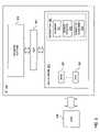
- FIG. 1is a diagram of a communication system capable of supporting Quality of Service (QoS) reservations, according to an embodiment of the present invention
- FIG. 2is a diagram of a satellite communication system capable of implementing a proxy architecture to provide QoS reservations, in accordance with an embodiment of the present invention
- FIG. 3is a diagram of the functional components of a satellite terminal (ST) that can support QoS services in the system of FIG. 2 ;
- FIG. 4is a flowchart of a process supported by the Dialer Proxy for establishing and releasing connections, according to an embodiment of the present invention
- FIG. 5is a flowchart of a process supported by the Dialer Proxy for matching user data, according to an embodiment of the present invention
- FIG. 6is a diagram of a Dialer Proxy in support of a multicast join/prune service, according to an embodiment of the present invention.
- FIG. 7is a state machine of a Dialer Proxy, according to an embodiment of the present invention.
- FIG. 8is a state machine of a Dialer, in accordance with an embodiment of the present invention.
- FIG. 9is a functional block diagram of an ST capable of supporting an H.323 proxying architecture, according to an embodiment of the present invention.
- FIGS. 10A and 10Bshow a flowchart of an H.323 proxy process for determining call type, according to an embodiment of the present invention.
- FIG. 11is a diagram of a computer system that is capable of supporting a proxying architecture, according to an embodiment of the present invention.
- QoSquality of service
- the present inventionis described with respect to a satellite communication system that supports data networking, it is recognized by one of ordinary skill in the art that the present invention has applicability to other data networks (e.g., terrestrial networks and radio communication systems).
- the present inventioninvolves the reservation of resources for a specific flow, whereby a specific performance guarantee between the ingress and egress of a network is ensured. Although this reservation capability is described with respect to use of connections, it is contemplated that other mechanisms exist to achieve this performance guarantee.
- FIG. 1shows a diagram of a communication system capable of supporting Quality of Service (QoS) reservations, according to an embodiment of the present invention.
- a wide area network (WAN) 101in an exemplary embodiment, is maintained by a service provider (e.g., carrier); the network 101 provides connectivity for a number of network elements 103 , 105 , 107 , 109 to a central office (CO) 111 .
- the network elements 103 , 105 , 107 , 109may be any type of networking device with the capability to communicate with the WAN 101 , such as a router, bridge, etc.
- QoS guaranteesare difficult to provide in an internetworked data communication system, in large part because QoS services are maintained at the end-user hosts (by the applications) wherein the intermediary network nodes or devices do not support such services (stemming from hardware and/or software incapabilities or lack of such hardware and/or software).
- the CO 111provides access to the public switched telephone network (PSTN) 113 .
- PSTNpublic switched telephone network
- the CO 111relays traffic from the PSTN 113 as well as the Internet 115 , to which the CO 111 is connected via an Internet Service Provider (ISP) 117 .
- ISPInternet Service Provider
- the WAN 101may be any type of network, such as a radio communication system (e.g., a digital cellular network, a packet radio network, a microwave network, etc.) or a terrestrial network (e.g., an Asynchronous Transfer Mode (ATM) network, frame relay network, etc.).
- the WAN 101may utilize any number of topologies—e.g., a fully meshed topology (i.e., connectivity).
- the network elements 103 , 105 , 107 , 109support proxies that transparently establish connections across the WAN 101 reflective of the dataflows required by the applications of the hosts (e.g., host 111 ).
- a connectionis reserved and established according to the requirements, such as connection rate, of the applications.
- the host 111which is connected to the network element 103 , is executing an application capable of exchanging real-time media streams, such as a Web browser.
- an applicationcapable of exchanging real-time media streams
- the host 119can retrieve multimedia content, such as streaming video.
- the host 119can be loaded with applications that support, for example, video monitoring, video conferencing, and voice over IP.
- the network element 103provides access to the WAN 101 , which has to transport the real-time traffic in addition to the vast amount of non-real-time traffic. These real-time applications require specific QoS guarantees to function satisfactorily.
- the H.323 protocolspecifies audio, video, and data communications across packet-based networks (e.g., Internet Protocol (IP) networks), and includes parts of H.225.0—Registration, Admission, Status (RAS), Q.931, H.245 Real-time Transport Protocol (RTP)/Real-time Transport Control Protocol (RTCP) and audio/video codecs, such as the audio codecs (G.711, G.723.1, G.728, etc.) and video codecs (H.261, H.263) that compress and decompress media streams.
- RTP/RTCPprovide transport of media streams, in which the RTP carries the actual media and RTCP carries status and control information.
- the signallingcan transported reliably using the Transmission Control Protocol (TCP).
- TCPTransmission Control Protocol
- the system 100utilizes a proxy architecture to provide QoS guarantees.
- One approach(“application specific proxy”) deploys an H.323 proxy in the network element to support connection-oriented services, such as point-to-point H.323 video calls.
- a protocol agnostic approachis also provided by the system 100 to permit use of an interface to provide adaptation from user applications to the resources of the network 101 , transparent to those applications. Both of these approaches, which can be implemented individually or in combination, are more fully described below.
- FIG. 2shows a diagram of a satellite communication system capable of implementing a proxy architecture to provide QoS reservations, in accordance with an embodiment of the present invention.
- the system of FIG. 2illustrates a specific implementation of the system of FIG. 1 , in which the WAN 101 is a satellite network and the network elements 103 , 105 , 107 , 109 are in form of satellite terminals.
- a satellite communication system 200utilizes a satellite 201 to transmit information to satellite terminals (STs) 203 , 205 , and a Network Operations Control Center (NOCC) 207 .
- the STs 203 , 205are Very Small Aperture Terminals (VSAT).
- VSATVery Small Aperture Terminals
- the satellite 201as a processing satellite capable of examining dataflows from the STs 203 , 205 , performs the necessary bandwidth control functions, in conjunction with the NOCC 207 .
- the STs 203 , 205originate traffic from a particular coverage area and may exchange data among other STs (not shown). Under this architecture, users can communicate from one VSAT ST to another directly with one satellite hop. That is, the system 200 provides mesh connectivity.
- the NOCC 207manages and controls communication services and operations. For example, the NOCC 207 provisions and identifies the communication channels that are to be allocated. Additionally, the NOCC 207 is responsible for controlling the bandwidth that is made available to the STs 203 , 205 . As seen in FIG. 2 , the NOCC 207 also provides interfaces, such as a gateway 213 , to either private Intranets (not shown) or the public Internet 113 via an ISP 215 . The NOCC 207 can support multiple receive channels (referred to as outroutes or downlinks) and multiple return channels (inroutes or uplinks); however, the NOCC 207 can be configured to provide no return channels, depending on the application.
- the receive support communication from the NOCC 207 to the STs 203 , 205while the return channels (if available) provide communication from the STs 203 , 205 to the NOCC 207 .
- the host 209 of the ST 203can download content from an application server 217 off the Internet 113 .
- the ST 205can provide access to the Internet 113 for host 219 over a local area network (LAN) 211 .
- LANlocal area network
- the satellite system 200provides end-users with connection-oriented services, which make use of capacity allocated to Network Service Providers (NSPs) according to uplink cells and also make use of Point-to-Point, replicated Point-to-Multipoint, and broadcast capabilities of the payload on the downlink.
- NSPsNetwork Service Providers
- the system 200supports connection management functionalities for setting up, modifying, and tearing down connections.
- a network level mechanismis provided for reserving bandwidth from the ingress point of the satellite system (user port of source ST) to the egress point(s) of the satellite system 200 .
- the egress point(s) of the satellite system 200may be the user port(s) of a single ST 203 or of several STs 203 , 205 which are members of a multicast group.
- the data rate of the connectionmatches the data rate defined by a Constant Rate parameter of the transport service of the system 200 .
- the system 200supports QoS services through the use of two proxy mechanisms, which can be utilized separately or in combination: (1) a protocol agnostic proxy (“Dialer Proxy”), and (2) a protocol specific (H.323) proxy.
- the Dialer Proxywhich operates in conjunction with a “Dialer” process, provides a connectionless, reliable resource reservation protocol.
- a Dialer Proxy 231is resident within the ST 205 , and a Dialer 223 is connected to the LAN 211 .
- the protocol specific proxye.g., H.323 proxy
- each of the STs 203 , 205is loaded with the H.323 proxy.
- the NOCC 207maintains a Gatekeeper 225 and supports a decomposed multipoint conference module via a centralized multipoint controller (MC) 227 that communicates with multiple multipoint processors (MPs) 231 , 233 distributed within the system 200 .
- MCmultipoint controller
- MPsmultipoint processors
- the Gatekeeper 225is an H.323 entity that provides call control services to H.323 endpoints.
- the Gatekeeper 225provides address translation (alias to network address translation), admission control (based on Call Authorization, Bandwidth etc), and bandwidth control and management.
- the MC 227performs conference control functions, such as a chair control capability.
- FIG. 3shows the functional components of an ST that can support QoS services in the system of FIG. 2 .
- the function of the ST 203 , 205is to transport user data according to the user applications resident on the hosts 209 , 211 .
- the ST 203 , 205performs a number of operations on incoming data before the data is sent over the satellite network 200 .
- These functionscollectively constitute the Internet Protocol (IP) adaptation process—that is, the adaptation of the user's offered data to the satellite network 200 .
- IPInternet Protocol
- the IP adaptation processincludes such actions as classifying flows of data (i.e., dataflows), using traffic acceleration techniques (or network performance enhancing functions) to adapt terrestrial protocols for use over satellite links, and establishing, using, and removing connections for applications with more stringent jitter and latency requirements.
- traffic acceleration techniquesor network performance enhancing functions
- network performance enhancing functionsare more fully detailed in commonly assigned co-pending application to Border et al., and entitled “Method and System for Improving Network Performance using a Performance Enhancing Proxy,” (Ser. No. 09/903,832 and Jul. 12, 2001) filed Jul. 12, 2001; the entirety is incorporated herein by reference.
- the ST 203 , 205can provide a configurable and expandable capability to monitor and manipulate user data for optimum QoS.
- an ST 203is divided into two major sections: a User Platform 301 and a Transport Platform 303 .
- the physical interface between these components 301 , 303is a Satellite System Transport Interface (SSTI) 305 .
- the Transport Platform 303is responsible for the satellite system specific tasks, such as performing Segmentation and Reassembly (SAR) on user packets and applying the proper headers for the satellite system, performing Bandwidth On Demand (BOD) and connection management signaling, transmitting and receiving user packets, and receiving and applying NOCC configuration information.
- SARSegmentation and Reassembly
- BODBandwidth On Demand
- connection management signalingtransmitting and receiving user packets, and receiving and applying NOCC configuration information.
- the tasks of the User Platform 301are performed by one or more User Port Adaptation Modules (UPAM) 307 , each of which adapts user data from one interface, such as a network interface (e.g., Ethernet), to the SSTI 305 for transmission over the satellite system 200 .
- UPAM 307is responsible for the performance enhancing features of the ST 203 , such as flow classification, as well as some satellite-specific functions, such as addressing.
- the SSTI 305adapts the logical functions of the Transport Platform 303 (send a user packet, establish a connection, look up the next hop address, etc.) to the UPAM functions.
- SSTI 303allows UPAM tasks, such as the network performance enhancing functions, to be developed without knowledge of the inner workings of the Transport Platform 303 .
- a well-defined set of messagesis exchanged across the SSTI 305 to request resources or information, such as a constant-rate connection or address resolution, thereby eliminating the need to know any satellite specific physical architecture. As a result, this UPAM architecture is easily adapted and extended.
- the User Platform 301includes several tasks that handle various functions relating to the adaptation of IP traffic.
- a task that is significant to the operation of connection managementis the satellite Transmit Task 309 , which is responsible for accepting user data and classifying the data for transmission by the Transport Platform 303 .
- the components of the Transmit Task 309include a Classifier module 311 , a satellite Address Resolution module 313 , and Connection Management module 315 (“Connection Manager”). These modules provide user data transport functions and services.
- the user data transport functionshave the responsibility of generating packets over the satellite network. Notably, such functions include mapping of flows of user data entering satellite network into the appropriate packet delivery service, based on, for example, the user's service profile, traffic conditioning specification, classification mapping rules, and policy.
- the Classifier module 311is responsible for applying Class of Service (CoS) tags to IP packets, based on, for example, configuration supplied by the Network Service Provider (NSP) on behalf of the user.
- These tagscan be configured, for example, on the basis of OSI (Open Systems Interconnection) Layer 3 and 4 traffic characteristics.
- the CoS tagscorrespond to the following classes: a Low Volume CoS, in which packets are prioritized if there are a relatively low number (i.e., volume) of such packets; a Best-Effort CoS, whereby these packets are allotted the leftover capacity that is unused by higher priority applications; and a Committed Rate CoS, in which the bandwidth rate and quality of service are guaranteed within that specified rate.
- these classes of servicecan be implemented by various User Data Transport Services (UDTS), as described below.
- UDTSUser Data Transport Services
- the User Data Transport Servicesinclude a Constant Rate service, a Constant Rate with Burst service, and Burst services (e.g., Normal and Low Volume Low Latency Burst service).
- the Constant Rate serviceallows user data that arrives at an ST at or below a specified data rate (in bits per second) to be delivered to a particular destination (one ST, or multiple STs by multicast) with minimum packet loss rate, and minimum latency.
- a maximum variationcan also defined, denoted “jitter,” in the times at which packets directed to a Constant Rate service can arrive at the ST.
- the STcan drop packets that are in excess of the data rate established for the particular Constant Rate service data flow.
- the Constant Rate with Bursts serviceis similar to Constant Rate service except that if an ST receives user data at a higher rate than the constant rate configured (or signaled) for the service, the ST will attempt to deliver some or all of the excess traffic to the specified destination. However, the excess traffic may have a high (but unspecified, and varying) delay and loss rate.
- This serviceis similar to terrestrial frame relay service which delivers data packets over connections that have a Committed Information Rate (CIR) with the ability to burst (or even sustain) higher rates if the network has the capacity to deliver the additional traffic.
- CIRCommitted Information Rate
- the Burst serviceresembles the Constant Rate with Bursts service, in which the Constant Rate is set to zero.
- the networkwill carry as much of the offered traffic as it can, but this traffic may experience a high (but unspecified, and varying) delay and loss.
- the Normal Priority Burst serviceis useful where the traffic to be carried is bursty and may involve high volumes during the bursts; for example, the traffic between a telecommuter's computer and a corporate LAN. In this scenario, there may be long periods with little or no activity with short periods of high traffic to transfer several Web pages or a file.
- the Constant Rate with Bursts (or even the Constant Rate) servicemight carry this traffic with a Quality of Service that is completely satisfactory to the user, but those two services are likely to use more network resources, and thus more costly than the Burst service.
- Low Volume Low Latency Burst serviceis useful for applications that have only short bursts but require minimum latency when there is data. For example, Point-of-sale transactions, such as credit card authorization, is such an application.
- UDTScan be implemented to support a variety of CoS (e.g., Low Volume, Best-Effort, and Committed Rate), such that new CoS classes can be readily created.
- CoSe.g., Low Volume, Best-Effort, and Committed Rate
- the address resolution module 313enforces Community of Interest (COI) restrictions, and maps IP addresses to Satellite Next-Hop Addresses (SNHA).
- COICommunity of Interest
- SNHASatellite Next-Hop Addresses
- the Connection Management module 315receives indications from the Classifier module 311 when a packet matching a specified connection trigger configuration is detected.
- the Connection Management module 315maintains the connection state machine, and handshakes with the Connection Management agent in the TP 303 to establish and tear town connections.
- proxiesare used to operate from the UPAM 307 to interface with the Classifier module 311 and Connection Management module 315 of the Transmit Task 309 .
- the SSTI 305can “export” the UPAM 307 to a separate physical device.
- a Voice over IP (VoIP) appliancecan be implemented that simply attaches to an off-the-shelf ST for providing telephone connections (e.g., RJ-11) for standard telephone sets, as well as converting analog voice data to IP packets, and forwarding the VoIP stream to a corporate gateway across the satellite network 200 , and then potentially to the PSTN.
- VoIPVoice over IP
- the UPAM 307 in the ST 203is disabled and replaced by an external UPAM, providing enhanced or application-specific functionality, in an external box.
- This external devicewould convert from the desired end-user protocol and link, such as IP over RJ-45 Ethernet or analog voice over RJ-11, to IP packets over SSTI 305 to the ST 203 . Because SSTI 305 is independent of the satellite system architecture, such a device could operate with any other broadband network that implements SSTI as its interface.
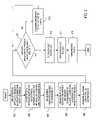
- FIG. 4shows a flowchart of a process supported by the Dialer Proxy for establishing and releasing connections, according to an embodiment of the present invention.
- the Dialer serviceis described with respect to the Dialer Proxy 231 and the Dialer 223 of the satellite system 200 .
- the Dialer Proxy 231provides a connectionless, reliable resource reservation protocol.
- the Proxy 231in an exemplary embodiment, operates over User Datagram Protocol (UDP), on a specified port number—which can be secured through Internet Assigned Numbers Authority (IANA).
- UDPUser Datagram Protocol
- IANAInternet Assigned Numbers Authority
- the Dialer serviceincludes three components: a Dialer device or software located at the end-user's equipment, a Dialer Proxy 231 located in the ST, and the Dialer Protocol—a UDP protocol allowing a Dialer 223 to request network services through the Dialer Proxy 231 .
- the purpose of the Dialer serviceis to allow end-user applications to access certain satellite system functionality without requiring frequent updates to the ST software to support new or proprietary applications.
- the functionality available through the Dialer serviceincludes point-to-point connection setup and termination, multicast connection setup and termination, and multicast group membership join and leave.
- the Dialer protocolis not specific to any application or service. Security is not provided by the protocol—any software may issue requests to the Proxy.
- the Dialer protocolallows for explicit triggers to be sent from user applications in the event that a service could not otherwise be supported by the ST. For example, if a protocol relies upon dynamic port assignment, standard classification mechanisms are insufficient to carry that flow over a dedicated connection. In this case, the Dialer protocol may be used to explicitly trigger the connection. The ST need not be adapted for every such protocol, since the Dialer protocol is generic.
- a user on the host 219initiates an application that requires connection-oriented service from the system 200 .
- an external devicesuch as the Dialer 223 , at the user's location detects this application's dataflow and extracts the information necessary to obtain a network connection, including flow source and destination IP addresses, transport layer protocol (UDP or TCP), source and destination port numbers, and connection rate.
- the connection raterefers to the uplink rate of the satellite system 200 .
- the Dialer 223transparently sniffs packets—i.e., the user's data packets are passed through unchanged to the ST 205 for transmission over the satellite 201 .
- the Dialer 223as in step 405 , sends a UDP Connection Setup Request message containing the extracted information and a unique transaction ID, to the configured ST, on a pre-established, known port.
- the Dialer 223maintains state information on each of its requests, and also maintains protocol timers to ensure requests are received. Each request is assigned a Connection ID (in the case of a connection request) or a Transaction ID (in the case of Group Join/Leave requests, as discussed later) by the Dialer 223 . These IDs are unique to the Dialer 223 , and are not to be reused for a specified period of time.
- the Dialer Proxy 231maintains information associating the requesting Dialer IP Address/Transaction ID pair with each request until the resources are released. A lost response from the Dialer Proxy 231 elicits a retry from the Dialer 223 of the request with the same Connection or Transaction ID. A release received for an unknown Connection ID is replied to with a Release Complete, indicating the connection is inactive. A Connection Request specifying a Connection ID which is already active is replied to with a Connection Acknowledgement (Ack), indicating the connection is available.
- a Connection Request specifying a Connection ID which is already activeis
- the Dialer Proxy 231 in the ST 205receives the UDP message, and requests the establishment of a new connection using a preconfigured Connection Configuration ID.
- This IDconfigured from the NOCC 207 beforehand, is known to the Dialer Proxy 231 , the User Platform Connection Manager 315 ( FIG. 3 ), and the Transport Platform 303 .
- the Dialer Proxy 231also configures a classifier rule with the flow criteria from the message.
- the Proxy 231Upon receiving a request from the Dialer 223 , the Proxy 231 requests a connection from the ST Connection Manager. This function requests a connection from the NOCC 207 . Until the NOCC 207 responds, no reply is sent back to the Dialer 223 . The NOCC 207 response determines whether the connection is accepted or not.
- a connectionis established between the ST 205 and a destination ST, such as ST 203 , per step 411 .
- any arriving user datais sent by whatever classification rule the data matches.
- the connection-oriented serviceis sent by the connection-oriented service.
- the user datais sent unchanged across the satellite system 200 to the receiving host 209 .
- the Proxy 231maintains a table of active Connection ID/Dialer IP pairs for the established connection.
- IDsmay be removed by a release request from a Dialer 223 (in which case the Proxy initiates clearing of the connection, and generates a Release Complete for the Dialer 223 ), or by notification from other ST elements that the connection and classification rules have been cleared.
- the Dialer Proxy 231returns a UDP message to the Dialer 223 containing a confirmation of connection establishment and a Connection Index (used when the Dialer 223 requests that the connection be torn down).
- the Dialer 223Upon detecting the end of dataflow, the Dialer 223 sends a release request, containing the Connection Index, to the Dialer Proxy 231 (step 417 ).
- the Dialer Proxy 231upon receiving a release request, releases the connection, and sends a confirmation message back to the Dialer 223 . Any time a connection is released, the Proxy 231 responds with a Connection Release Complete to the Dialer 223 which is responsible for the connection.
- the Proxy 231responds to release requests from the Dialer 223 with unknown Connection IDs with a Release Complete, indicating that there are no resources assigned.
- FIG. 5shows of a process supported by the Dialer Proxy for matching user data, according to an embodiment of the present invention.
- a userinitiates an application that requires multicast connection-oriented service.
- the Dialer 223detects this application's dataflow and extracts the information necessary to obtain a multicast connection, including, for example, flow source IP address, destination Class D multicast IP address, source and destination UDP port numbers, and connection rate.
- the user packetsare passed unchanged to the ST 205 .
- the Dialer 223sends a UDP Connection Setup Request message, containing the extracted information and a unique transaction ID, to the configured ST 205 , on a pre-established, known port.
- the Dialer Proxy 231 in the ST 205receives the UDP message, and requests the establishment of a new multicast connection using a pre-configured Connection Configuration ID that is obtained from the NOCC 207 in advance.
- the IDis known to the Dialer Proxy 231 , the User Platform Connection Manager 315 , and the Transport Platform 303 .
- the Dialer Proxy 231also configures a classifier rule with the flow criteria from the message.
- the multicast connectionis then established to the destination STs (of which only ST 203 is shown) via the satellite 201 .
- any arriving user datais dropped, as multicast data is sent on an established connection (per step 511 ).
- the Classifier module 311examines another set of rules, sequencing through a predetermined list of rules; the subsequent set of rules can be more generic or correspond to a different application.
- the connectionis established, the user data matching the characteristics specified in the Dialer's request is sent by connection-oriented service, and replicated by the payload to the receiving STs 203 (per steps 515 - 519 ).
- User datais unchanged when forwarded to receiving hosts (e.g., host 209 ).
- FIG. 6shows a diagram of the Dialer Proxy in support of a multicast join/prune service, according to an embodiment of the present invention.
- the satellite system 200can provide dynamic multicast group membership, even though the ST 205 does not support a multicast routing protocol (e.g., Protocol-Independent Multicast/Sparse Mode (PIM/SM)).
- PIM/SMProtocol-Independent Multicast/Sparse Mode
- the routers within the LAN 211can be statically configured with multicast group membership according to PIM/SM or another multicast routing protocol.
- the Dialer 223 located on the LAN 211can directly request multicast joins and prunes at the ST 205 through the Dialer Proxy 231 .
- the multicast group ID(MGID) is preconfigured at the NOCC 207 and the ST 203 ; the Dialer Proxy 231 enables or disables reception of the multicast data the satellite 201 and forwards the data out a terrestrial interface of the ST 205 . This joining/pruning process is described as follows.
- Multicast group membershipmay be requested with a Multicast Join/Leave Request.
- an application on the host 219sends an IGMP message requesting a join or prune from a specified Class D multicast IP address.
- the Dialer 223 located on the LAN segment of the host 219receives the IGMP message.
- the Dialer 223then extracts the pertinent data from the IGMP message and prepares a new request message for forwarding to a configured ST IP address and pre-established UDP port of the ST 205 , per step 603 .
- the IGMP messagecan be encapsulated within the new request message.
- the Dialer Proxy 231 in the ST 205receives the multicast join/prune request.
- the User Platform of the ST 205associates the Class D address with an MGID (this mapping is pre-configured), and sends a join request across the SSTI. If the ST 205 is able to join the multicast, the Proxy 231 responds to the Dialer 223 with a Multicast Join/Leave Indication specifying that the group has been joined, and the requesting Dialer 223 is registered as a receiver. Multiple Dialers may join the same multicast.
- the ST 205then sends a dynamic Join Request message to the NOCC 207 and begins to receive the multicast data from the satellite 201 .
- the multicast group trafficis forwarded by the ST 205 to the LAN 211 , as in step 607 .
- the multicast-enabled routers within the LAN 211then propagate, as in step 609 , the multicast traffic to the client application of the host 219 .
- a Dialer 223seeks to leave a multicast group, another Multicast Join/Leave Request may be sent specifying an action of “Leave.”
- the Dialer Proxy 231responds with a Multicast Join/Leave Indication specifying that the Dialer 223 is no longer registered as a receiver. If this is the last Dialer 223 to leave a group, and there are no other Internet Group Management Protocol (IGMP) hosts receiving the multicast, the Proxy 231 also initiates removal of the ST (e.g., ST 203 ) from that multicast group.
- IGMPInternet Group Management Protocol
- the Dialer Proxy 231sends Multicast Join/Leave Indications to all Dialers who were registered to receive that multicast, specifying that they are no longer registered receivers. If a Join request does not succeed, the Dialer 223 responds with a Multicast Join/Leave Reject, indicating that the request failed. The Dialer 223 waits and retries after a specified period.
- FIG. 7shows a state machine of the Dialer Proxy, according to an embodiment of the present invention.
- the state machines of FIGS. 7 and 8show the exchange of messages between the Dialer Proxy 231 and the Dialer 223 with respect to establishment and tear-down of unicast and multicast connections in support of the connection-oriented services of the system 200 .
- timersare maintained for the Dialer service. Typical delays between sending a Connection Request and receiving an Acknowledge or Reject may be of the order of 5-6 seconds. Delays of up to 30 seconds are possible. For that reason, timers on the Dialer 223 are set accordingly to minimize repeated requests.
- the Dialer Proxy 231is in an Idle state 701 , and transitions to a Connection Pending state 703 upon transmission of a Connection Request message (CONN_REQ) to the Dialer 223 .
- a timeris started upon sending of this request, and stopped upon receiving of a Connection Acknowledgement message (CONN_ACK) or a Connection Rejected message (CONN_REJ). However, upon expiration (e.g., a default value of 4 seconds), the CONN_REQ message is retransmitted.
- the Dialer Proxy 231maintains a Connection Request Backoff timer (CONN_REQ_BACKOFF) to reinitiate the connection request, assuming the connection establishment is still desired.
- CONN_REQ_BACKOFF timeris started when the number of retries of the connection request is exhausted or upon receipt of a connection rejection message (CONN_REJ). To track the number of retries, a retry counter is maintained.
- the CONN_REQ messagein an exemplary embodiment, includes a field to specify the connection type (e.g., unicast or multicast) and associated service characteristics. Additionally, the CONN_REQ message contains a classification flags field for indicating which classification fields are to be considered in matching the dataflow. A Flow Source IP Address field and a Flow Destination IP Address field are included in the CONN_REQ message; these fields can be used to map the flow to the connection.
- connection Pending state 703the Connection Established state 705 is reached upon transmitting the CONN_ACK message; however, if the connection is rejected by issuance of the CONN_REJ message, then the Dialer Proxy 231 returns to the Idle state 701 .
- a requestmay be “cancelled” while in progress through the issuance of a “Release” message.
- a Connection Requestmay be followed by a Connection Release if the Dialer 223 “changes its mind”.
- a Multicast Joinmay be followed by a Multicast Leave.
- the Proxy 231suspends processing of the request and cleans up any resources allocated before acknowledging the Release or Leave.
- the Dialer Proxy 231When a connection is established (i.e., the Dialer Proxy 231 is in the Connection Established state 705 ), the Dialer Proxy 231 enters a Connection Release Pending state 707 upon receiving a Connection Release message (CONN_REL). A timer associated with the connection release is maintained, such that the CONN_REL message is retransmitted upon expiration. This timer is started upon sending of the CONN_REL message and stopped upon receipt of a Connection Release Acknowledgement message (CONN_REL_ACK). The Dialer Proxy 231 can also provide a retry counter to track the number of attempts at releasing the connection.
- CONN_RELConnection Release Acknowledgement message
- the Dialer Proxy 231can send a Connection Release Completed message (CONN_REL_CMP) to release the connection and return to the Idle state 701 .
- This messagealso has an associated timer, denoted Connection Identification Reuse time, which is started with the Dialer 223 receives the CONN_REL_CMP message. Upon expiration of this time, the connection having the particular ID is released and can be reused.
- the Dialer Proxy 231enters the Multicast Join/Leave state 709 through receipt of a Multicast Join Request message (MC_J_REQ) and subsequent Multicast Leave Request message (MC_L_REQ). If the Dialer Proxy 231 rejects the Multicast Join Request message or sends a Multicast Leave Acknowledgement message (MC_L_IND), then the Dialer Proxy 231 reverts to the Idle state 701 .
- the Dialer Proxy 231enters a Multicast Join/Leave Established state 711 by submitting a Multicast Join Indication message (MC_J_IND), and transitions to the Idle state 701 through transmission of a Multicast Leave Indication message (MC_L_IND).
- Timersare utilized to support initiation of the Leave and Join requests.
- a Multicast Join/Leave (MC_JL_REQ) Request timeris used to retransmit a request, and is started upon sending of the join or leave request.
- This MC_JL_REQ timeris ceased when a corresponding acknowledgement message is received.
- a backoff timer (MC_JL_REQ_BACKOFF)is maintained to reinitiate the request, operating in similar fashion as that of the CONN_REQ_BACKOFF timer.
- the request to join or leavealso has a retry counter such that exceeding the specified value either instructs the Dialer 223 to backoff according to the MC_JL_REQ_BACKOFF timer (if the request is to join) or instructs release of the resources (if the request is to leave).
- FIG. 8is a state machine of the Dialer, in accordance with an embodiment of the present invention.
- the Dialer 223begins in an Idle state 801 and supports establishment of a connection through transitioning to a Connection Pending state 803 by sending a Connection Request message (CONN_RQST). If the connection request is rejected, whereby the Dialer 223 receives a Connection Rejected message (CONN_REJ), then the Dialer 223 returns to the Idle state 801 . Otherwise, the Dialer 223 transitions into a Connection Established state 805 , upon receipt of an acknowledgement message (CONN_ACK) that the connection request is honored.
- CONN_ACKacknowledgement message
- the Dialer 223can enter a Connection Release Pending state 807 upon issuing a Connection Release message (CONN_REL) while in the Connection Established state 805 , or from transmitting a Connection Release message (CONN_REL) from the Connection Pending state 803 .
- the Dialer 223returns to the Idle state 801 from the Connection Release Pending state 803 by transmitting a Connection Release Complete (CONN_REL_CMP) message.
- the Dialer 223submits a Multicast Join Request message (MC_J_REQ), thereby entering a Multicast Join Leave Pending state 809 .
- MC_J_INDMulticast Join Indication message
- the Dialer 223transitions to a Multicast Join state 811 .
- the Dialer 223sends a Multicast Leave Request message (MC_L_REQ), causing the Dialer 223 to enter the Multicast Join/Leave Pending state 809 .
- the Dialer 223then returns to the Idle state 801 in response to receiving a Multicast Leave Indication message (MC_L_IND).
- Alarm Code messagethat identifies the type of error encountered (e.g., unknown protocol, invalid message, or supported extension)
- Dialer Heartbeatissued by the Dialer 223 to indicate to the Dialer Proxy 231 that it is up
- Proxy Heartbeatissued by the Dialer Proxy 231 to indicate to the Dialer 223 that it is up.
- the Dialer Proxy 231responds with an alarm message.
- the alarm messageis issued when, for example, a request specifies a protocol version greater than the version the Proxy 231 supports.
- the unrecognized messagescould be caused by a lost message, for example, a Connection Request when the connection is established, a Connection Release when the connection does not exist, a Multicast Leave when the Dialer 223 is not a member, the Proxy responds with the appropriate acknowledgement of the current state.
- the responsesinclude Connection Ack, Release Complete, and Join/Leave Indication.
- Extension fields for each messageare used to provide backward compatibility in later developed protocols. These fields follow the Type Length Value (TLV) format—each extension specifies a Tag which identifies the parameter, a Length which specifies the length of the parameter, and a Value field, which specifies the data. Capabilities can therefore be added as feature sets, rather than new protocol versions. Extension parameters are optional (Proxy or Dialer 223 may ignore if not understood), or mandatory (Proxy 231 or Dialer 223 should abort if not understood). If an unsupported mandatory extension parameter is specified in a request to the Dialer Proxy 231 , the Proxy 231 responds with an alarm message identifying the first unsupported parameter.
- TLVType Length Value
- Re-boot and failure scenarios for the Proxy 231are handled through heartbeat messaging from Dialer Proxy 231 to each Dialer 223 for which the Proxy 231 has some state. These periodic messages contain the time the particular instance of the Proxy 231 started. If the Proxy 231 reboots or otherwise loses state information unexpectedly, this non-repeating time field is updated accordingly.
- the Dialer 223compares each received heartbeat with the time from the previous heartbeat. If the time has changed, the Dialer 223 responds by removing its state accordingly for all those transactions that were lost. They may then be re-requested. The Proxy 231 will process these “new” requests accordingly, re-synchronizing the Dialer 223 and Proxy 231 .
- the Dialer 223In the event the heartbeat message is not received by a Dialer 223 for a set time, the Dialer 223 considers that Proxy 231 as being down, and all of its transactions are considered released. The Dialer 223 sends release requests for each transaction using the normal procedure, to handle the situation where the Proxy 231 is up but packets are being lost in transit between Proxy 231 and Dialer 223 . The Dialer 223 can select to use another Proxy (if available), or continue trying requests to the failed Proxy 231 . Dialers will ignore heartbeats from Proxies it is not receiving services from, and do not send heartbeats to those Proxies.
- Dialer Proxy 231fails to receive a heartbeat from a Dialer 223 for which it is maintaining state, the Proxy 231 issue Release Complete/Leave Indication messaging and clear all state maintained for that Dialer 223 .
- the Dialer Proxy 231will ignore heartbeats from Dialers for which it has no state, and shall not send a heartbeat of its own to those Dialers.
- the Dialer 223 and the Dialer Proxy 231can operate with the H.323 proxy 221 to further provide enhanced services relating to QoS.
- FIG. 9shows a functional block diagram of an ST capable of supporting an H.323 proxying architecture, according to an embodiment of the present invention.
- ST 205includes a Transport Platform 901 , an SSTI interface 903 , and a User Platform 905 , similar to that of the terminal of FIG. 3 .
- the User Platform 905includes a Receive Task 907 and a Transmit Task 909 .
- the Transmit Task 909possesses a Classifier 911 and a Connection Management module 913 .
- the H.323 proxy 221transparently examines messages on specified TCP ports related to H.323 call setup.
- RTPReal-Time Protocol
- UDPUser Datagram Protocol
- the H.323 proxy 221dynamically creates new classifier rules to map the flow to a connection and initiates connection setup at the desired rate.
- the H.323 client-negotiated call ratecan be scaled by a configured amount in requesting the satellite connection.
- the host 219transmits IP packets over the LAN 211 , which interfaces with an IP Task 915 of the ST 205 .
- the IP Task 915has responsibility for determining whether the packets are to be transmitted to the satellite 201 . If not, the IP Task 915 directs the packets back to the LAN 211 . However, if the packets are to be carried over the satellite system 200 , the IP Task 915 checks if the packets need to be sent through a particular proxy (assuming multiple proxies are utilized) by checking, for example, the packet's micro-flow (i.e., source and destination IP and port numbers).
- a particular proxyassuming multiple proxies are utilized
- any proxy that is supported by the STcan be the recipient of this traffic, depending on the application.
- the proxyis the H.323 proxy 221 ; consequently, if the IP Task 915 detects any packets relating to H.323 specific messages, these packets will be sent to the H.323 proxy 221 .
- the H.323 proxy 221then checks for the specific H.323 messages that are needed to be analyzed and interpreted, in which certain parameters relating to connection establishment are determined from these messages are stored. Such messages are forwarded to the Gatekeeper 225 for processing.
- the Gatekeeper 225After analyzing the specific H.323 messages, the Gatekeeper 225 sends these H.323 messages back to the IP Task 915 .
- classification rulesare dynamically assigned on the IP Task 915 to allow certain more specific messages to be directed to the Gatekeeper 225 .
- the Gatekeeper 225interfaces with the Classifier 911 to dynamically assign User Data Transport Service (UDTS) rules to certain messages, and with the Connection Management function 913 to dynamically open connections for RTP streams.
- UDTSUser Data Transport Service
- the packets from the satellite 201are received by the Receive Task 907 of the ST 205 . These received packets are sent to the IP Task 915 , which will check if any of the messages should be sent to the Gatekeeper 225 , based on the micro-flow. After analyzing the specific H.323 messages, the Gatekeeper 225 sends these H.323 messages back to the IP Task 915 and would dynamically assign rules as described above.
- the H.323 proxy 221permits dynamic determination of the IP traffic characteristics to support, for example, connection-oriented service for H.323 video conferencing.
- Traditional IP-networksdo not necessarily enable a guaranteed bandwidth for real-time traffic.
- the satellite system 200can readily support QoS. Beyond merely establishing priority for a dataflow, the H.323 proxy 221 supports establishment of a dedicated circuit for the identified dataflow.
- each H.323 callrequires two connections: one for video data and one for audio data.
- These connection configurationsare provided in advance, and contain the generic properties of the connections, including queue depth and the number of instances allowed.
- the proxy 221detects call-termination signaling, the proxy 221 removes the dynamically inserted classification rules, and terminates the connections.
- the H.323 proxy 221is to ensure that participants in each call are registered to an allowed Gatekeeper before providing Connection-Oriented service to the dataflow. This ensures that only authorized users of the video conferencing service receive premium service, and that the necessary call records will be generated by the Gatekeeper 225 , which provides call control services to H.323 endpoints. This determination relies on Gatekeeper-routed call setup signaling, in which all call-signaling messages are either sent by or to the Gatekeeper 225 . Therefore, the H.323 proxy 221 compares the source and destination IP address of each call-signaling message to a list of configured “trusted” Gatekeepers. If neither address matches, the Proxy 221 ignores the call, and does not set up connections or classification rules.
- H.323 clientsare configured with their associated Gatekeeper's address.
- H.323also supports a means of dynamic Gatekeeper discovery so that a client may “discover” that particular Gatekeeper 225 it should register with among multiple Gatekeepers (in which FIG. 2 illustrates a single Gatekeeper 225 ).
- Gatekeeper Discoveryis initiated, for instance, by a client sending a multicast packet to a well-known multicast address. Upon receiving such a packet, the Gatekeeper 225 replies with a unicast packet to the client, informing it of the Gatekeeper's presence.
- the H.323 proxy 221supports tunneling these messages across the satellite system to a designated ST. When the H.323 proxy 221 receives this multicast Gatekeeper Discovery packet, the proxy 221 encapsulates the multicast packet into a unicast packet addressed to the Gatekeeper's ST IP Address, and forwards the packet over the satellite system 200 .
- the Gatekeeper's ST H.323 proxy(not shown) receives this unicast packet, decapsulates the multicast packet, and forwards it out the user port for receipt by the Gatekeeper 225 .
- Thisallows the Gatekeeper Discovery process to function as though the Gatekeeper 225 were located on a local LAN.
- the above approachavoids a Gatekeeper Request (GRQ) multicast message to be sent over the satellite 201 . If the host 219 is not configured with the Gatekeeper's IP address, the host 219 cannot register with the Gatekeeper 225 , thereby preventing the host 219 from being able to take advantage of bandwidth reservation through H.323 proxy, since the proxy 221 will not engage unregistered users.
- GRQGatekeeper Request
- Registration, Admission and Status (RAS) signaling functionuses H.225 messages to perform registration, admissions, bandwidth changes, and disengage procedures between endpoints and Gatekeepers (e.g., Gatekeeper 225 ).
- Gatekeeperse.g., Gatekeeper 225
- the RAS signaling functionis not used.
- the RAS signaling channelis opened between the endpoint and the Gatekeeper 225 .
- the RAS message exchangesinclude GRQ (Gatekeeper Request)/GCF (Gatekeeper Confirm) for discovery, RRQ (Registration Request)/RCF (Registration Confirm) for registration, ARQ (Admission Request)/ACF (Admission Confirm) for admission, BRQ (Bandwidth Request)/BCF (Bandwidth Confirm) for bandwidth changes, DRQ (Disengage Request)/DCF (Disengage Confirm) for Disengage.
- GRQ/GCF discovery message exchangecan be avoided by specifying Gatekeeper's network address.
- RRQ/RCF messagesare exchanged in order to register the endpoint with the Gatekeeper 225 .
- ARQ/ACF messagesare exchanged with the Gatekeeper 225 to obtain admission for a call; this occurs immediately before the call setup. Thus, the delay in exchanging these messages would affect the delay in call setup only.
- BRQ/BCF message exchangeoccurs during a call for bandwidth changes, for which the logical channels that were previously opened for a media should be re-opened with the new bandwidth.
- DRQ/DCF message exchangeis performed just after the end of the call, to disengage from the Gatekeeper 225 .
- the Gatekeeper deployment modeldirectly influences the handling/routing of the Gatekeeper discovery (GRQ) and other RAS messages across the satellite system.
- GRQGatekeeper discovery
- all the H.323 terminalswill be pre-configured with the IP address of the respective zone's Gatekeeper.
- the terminalThere will be no GRQ message from the H.323 terminals, and the first RAS message that is sent by the H.323 terminal application at startup, is the Registration Request (RRQ) to register with the pre-configured Gatekeeper. If a H.323 terminal does not have a Gatekeeper defined, the terminal would send a GRQ request (if Gatekeeper discovery is configured in the client) over the satellite system using a pre-designated IP multicast address.
- RRQRegistration Request
- the satellite terminals 203 , 205exchange the above H.225 messages to fully function with the Gatekeeper 225 .
- Each message-exchangerequires one satellite round trip. Consequently, the H.323 messages have corresponding expiry timers, which are set to greater than the added satellite roundtrip delays.
- a “zone”is defined as the collection of all terminals, gateways, and Multipoint Controller 227 managed by a single Gatekeeper 225 .
- a single Gatekeeper 225is utilized per zone.
- a zonemay be independent of network topology and may be comprised of multiple network segments, which are connected via routers or other network devices.
- Networks that contain gatewaysinclude a Gatekeeper 225 , for example, to translate incoming dialed digit addresses into network addresses.
- the H.323 point-to-point callcan still be established.
- the terminalcalls a Multipoint Controller (MC) 227 .
- MCMultipoint Controller
- a usercan download any H.323 client on the local host 209 and use a video camera to initiate a video conferencing call, without registering with the Gatekeeper 225 ; however, such a call cannot make use of the standard functions of the Gatekeeper 225 .
- Gatekeeperscan be situated at a central location, such as in an Enterprise headquarters network. Unless the H.323 terminals register with the Gatekeeper 225 , the calls cannot be tracked or reported. The Gatekeeper 225 sends out usage reports of video conferencing calls among registered terminals.
- Guaranteed bandwidth over the satellite systemare offered to only those terminals that register with the Gatekeeper using an admission control mechanism, such as username/password authorization. For instance, capturing Q.931 call setup message can identify the terminal that is unregistered to the Gatekeeper 225 .
- H.323 standardsupports two distinct multipoint conference modes—centralized and decentralized.
- both the Multipoint Controller (MC) and the Multipoint Processor (MP) constituting the Multipoint Control Unit (MCU)are centrally located, whereby all the H.323 terminals call the MCU to participate in the multipoint conference.
- These terminalsperform call setup, H.245 Master/Slave determination, H.245 terminal capability exchange, H.245 logical channel messaging with the MC of MCU and the RTP streaming (using unicast) with the MP of MCU.
- the MP part of the MCUmixes the Audio/Video streams on a “per terminal” basis and unicasts the mixed audio/video streams to each terminal.
- This approachis not desirable over the satellite system because the RTP streaming occurs over the satellite link using unicast from all the terminals.
- the MCUsends multiple mixed RTP unicast streams unicast to the terminals. Because the MCU is centrally located, all the RTP streams are sent over the satellite link twice, thus incurring a large delay in transmission of the streams.
- the endpointsi.e., hosts
- the endpointshave the MP capability built into them. These endpoints receive multicast video channels and select one or more of the available channels for display to the user.
- the endpointsalso receive multicast audio channels and perform an audio mixing function in order to present a composite audio signal to the user.
- the Multipoint ControllerMC is at a central location, while the MPs are resident in the hosts. This approach is not practical in terms of cost, as the MP functionality is required at the endpoints, thereby requiring high-end computing systems or an add-on device containing the MP.
- the satellite system 200overcomes the drawbacks of the conventional centralized and decentralized approaches by employing a “decomposed” multipoint conference. model.
- the decomposed MCU modelutilizes a centralized MC 227 with multiple MPs 232 , 233 located in the network.
- the MC 227controls the MPs 232 , 233 located at the STs 203 , 205 using specific protocols, such as H.248 by MEGACOTM.
- MEGACOTMis a general-purpose gateway-control protocol standardized in the IETF as RFC 3015 and as recommendation H.248 in the ITU-T.
- Each MP 232 , 233multicasts the streams to other MPs 232 , 233 .
- This decomposed MCU modelis transparent to the H.323 end terminals, acting as a single centralized MCU for the H.323 terminals.
- terminalsopen the logical channels with the MC 227 .
- the MC 227instructs the terminals to unicast their RTP streams to the nearest MP's RTP/RTCP ports.
- MPs 232 , 233receive the unicast from the local terminals, which in turn multicast to all other participating MPs 232 , 233 .
- the local terminalsalso receive the multicast from other MPs 232 , 233 via the ST 203 , 205 .
- MPs 232 , 233mix the RTP streams by removing local audio for echo suppression separately for each local terminal and send the streams (using unicast) to the respective terminals.
- the decomposed MCU modeladvantageously minimizes delay in multipoint video conferencing over the satellite system in that the RTP streams are sent over the satellite once, and the MP capability is resident in the STs 203 , 205 or co-located with the STs 203 , 205 .
- the hosts 209 , 219need not be high-end machines or have an MP device.
- the RTP streamswould be multicasted from each ST. This causes the flow of multiple multicasts from each ST to other STs participating in the multipoint conference, thereby enabling a single hop of RTP streams over the satellite network, reducing the latency in the transmission of the media within acceptable limits for an interactive application like video conferencing.
- H.323 protocoluses standard ports for certain H.323 messages (H.225/RAS uses 1719 , H.225/Q.931 uses 1720 ), the port number for H.245 and the RTP/RTCP (Real Time Transport and its control) port numbers for each media stream are dynamic.
- the H.323 proxy 221is used in identification of the specific H.323 message and the bandwidth to be reserved for the RTP streams.
- the H.323 proxy 221for example, in the User Platform 905 of ST 205 serves these functions for H.323 video conferencing.
- the H.323 proxy 221receives certain selected H.323 messages (e.g., Q.931 and H.245) that are needed for setting up guaranteed bandwidth over the satellite network 200 .
- the proxy 221does not terminate the H.323 messages, but interpret the messages to look for certain parameters like port numbers, bit rate needed for the logical channel, and type of call (point-to-point or a multipoint). This process is explained below with respect to FIGS. 10A and 10B .
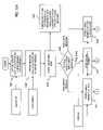
- FIGS. 10A and 10Bshow a flowchart of an H.323 proxy process for determining call type, according to an embodiment of the present invention.
- the H.323 proxy 221has to capture the Open Logical Channel (OLC) set of messages for both point-to-point and multipoint calls for making a connection request (CR) with the NOCC 207 .
- OLCOpen Logical Channel
- the H.323 proxy 221captures the call messages between the terminals (under different STs).
- the H.323 proxy 221captures the call messages between the Multipoint Controllers (MCs) (participating in a cascade).
- MCsMultipoint Controllers
- the H.323 proxy 221examines a Q.931 Setup message to capture the MC Boolean value and Conference ID information (if a multipoint call), per step 1001 . Similarly, the H.323 proxy 221 also captures the Boolean value of the MC parameter in a Q.931 Connect message, as in step 1003 . The proxy 221 identifies the H.245 port and stores this information, per step 1005 . In step 1007 , the proxy 221 interfaces with the IP task 915 to forward all the H.245 messages to the proxy 221 .
- the proxy 221sets a rule in the Classifier 911 to assign a satellite connection (e.g., normal priority burst User Data Transport Services (UDTS)) to the H.245 messages.
- a satellite connectione.g., normal priority burst User Data Transport Services (UDTS)
- UDTSUser Data Transport Services
- the H.323 proxy 221determines whether there is a match between the MC values in the Setup and Connect messages. The proxy 221 identifies the call as point-to-point, assuming the MC value in both the Setup and Connect messages is “False.” If one of the MC values is “True” in either message, then the proxy 221 determines that this is a decomposed multipoint call. The proxy 221 matches the retrieved conference ID from the Connect message with that of the conference ID contained in the Setup message.
- UDTSUser Data Transport Services
- the proxy 221concludes that the call is a cascaded multipoint call.
- the conference ID of the Connect messageis matched with that of the conference ID in the setup message.
- the H.323 proxy 221examines the H.245 OLC message, the proxy 221 stores the channel number and bit rate from this message, per step 1011 . After the proxy 221 receives the OLCAck for this OLC message, the proxy 221 subsequently checks for the RTP/RTCP IP addresses and port numbers, storing these parameters (step 1013 of FIG. 10B ). The proxy 221 then interfaces with the connection manager to open connection over the satellite 201 using these parameters, as in step 1015 . In addition, the proxy 221 sets a rule in the Classifier 911 to apply the appropriate CoS tag; e.g., CR UDTS to the RTP streams. If the tag is that of the Low Volume CoS, then a Low Volume Low Latency UDTS is employed. In the case of the Best-Effort CoS, either the Normal Burst UDTS or the Low Volume Low Latency Burst UDTS can be used depending on the application.
- the appropriate CoS tage.g., CR UDTS
- the OLC/OLCAck messagesare for the H.323 terminals to unicast to the MPs, and not for the MPs to multicast the streams out, the OLC/OLCAck are captured by the H.323 proxy 221 to store the channel number and the MP's IP address, per steps 1019 and 1021 .
- the class D IP and port, and bit rateare captured, as in step 1021 .
- the proxy 221then interfaces with the connection manager 913 to open a connection, as in step 1015 , based on these parameters, and sets a rule in the Classifier 911 to assign CR UDTS to the RTP streams, per step 1023 .
- the class D IP and port, channel number and bit rate from OLCare stored (step 1025 ).
- the proxy 221interfaces with the connection manager 913 to open a connection over the satellite system 200 according to these parameters (step 1027 ).
- the proxy 221also sets a rule in the Classifier 911 to assign CR UDTS to the RTP streams.
- the proxy architectures described aboveadvantageously provide resource reservation in addition to the actual establishment of the connection.
- the protocol agnostic proxy (Dialer Proxy), and the protocol specific (H.323) proxy approacheswhich can be deployed separately or in combination, ensures that Quality of Service levels are guaranteed, particularly with respect to real-time streams (e.g., voice of IP, audio streaming, video streaming, and video conferencing).
- FIG. 11is a diagram of a computer system that is capable of supporting a proxying architecture, according to an embodiment of the present invention.
- the computer system 1100includes a bus 1101 or other communication mechanism for communicating information and a processor 1103 coupled to the bus 1101 for processing information.
- the computer system 1100also includes main memory 1105 , such as a random access memory (RAM) or other dynamic storage device, coupled to the bus 1101 for storing information and instructions to be executed by the processor 1103 .
- Main memory 1105can also be used for storing temporary variables or other intermediate information during execution of instructions by the processor 1103 .
- the computer system 1100may further include a read only memory (ROM) 1107 or other static storage device coupled to the bus 1101 for storing static information and instructions for the processor 1103 .
- a storage device 1109such as a magnetic disk or optical disk, is coupled to the bus 1101 for persistently storing information and instructions.
- the computer system 1100may be coupled via the bus 1101 to a display 1111 , such as a cathode ray tube (CRT), liquid crystal display, active matrix display, or plasma display, for displaying information to a computer user.
- a display 1111such as a cathode ray tube (CRT), liquid crystal display, active matrix display, or plasma display
- An input device 1113is coupled to the bus 1101 for communicating information and command selections to the processor 1103 .
- a cursor control 1115is Another type of user input device, such as a mouse, a trackball, or cursor direction keys, for communicating direction information and command selections to the processor 1103 and for controlling cursor movement on the display 1111 .
- the Dialer services functionsare implemented by the computer system 1100 in response to the processor 1103 executing an arrangement of instructions contained in main memory 1105 .
- Such instructionscan be read into main memory 1105 from another computer-readable medium, such as the storage device 1109 .
- Execution of the arrangement of instructions contained in main memory 1105causes the processor 1103 to perform the process steps described herein.
- processors in a multi-processing arrangementmay also be employed to execute the instructions contained in main memory 1105 .
- hard-wired circuitrymay be used in place of or in combination with software instructions to implement the embodiment of the present invention.
- embodiments of the present inventionare not limited to any specific combination of hardware circuitry and software.
- the computer system 1100also includes a communication interface 1117 coupled to bus 1101 .
- the communication interface 1117provides a two-way data communication coupling to a network link 1119 connected to a local network 1121 .
- the communication interface 1117may be a digital subscriber line (DSL) card or modem, an integrated services digital network (ISDN) card, a cable modem, a telephone modem, or any other communication interface to provide a data communication connection to a corresponding type of communication line.
- communication interface 1117may be a local area network (LAN) card (e.g. for EthernetTM or an Asynchronous Transfer Model (ATM) network) to provide a data communication connection to a compatible LAN.
- LANlocal area network
- Wireless linkscan also be implemented.
- communication interface 1117sends and receives electrical, electromagnetic, or optical signals that carry digital data streams representing various types of information.
- the communication interface 1117can include peripheral interface devices, such as a Universal Serial Bus (USB) interface, a PCMCIA (Personal Computer Memory Card International Association) interface, etc.
- USBUniversal Serial Bus
- PCMCIAPersonal Computer Memory Card International Association
- the network link 1119typically provides data communication through one or more networks to other data devices.
- the network link 1119may provide a connection through local network 1121 to a host computer 1123 , which has connectivity to a network 1125 (e.g. a wide area network (WAN) or the global packet data communication network now commonly referred to as the “Internet”) or to data equipment operated by a service provider.
- the local network 1121 and the network 1125both use electrical, electromagnetic, or optical signals to convey information and instructions.
- the signals through the various networks and the signals on the network link 1119 and through the communication interface 1117 , which communicate digital data with the computer system 1100are exemplary forms of carrier waves bearing the information and instructions.
- the computer system 1100can send messages and receive data, including program code, through the network(s), the network link 1119 , and the communication interface 1117 .
- a server(not shown) might transmit requested code belonging to an application program for implementing an embodiment of the present invention through the network 1125 , the local network 1121 and the communication interface 1117 .
- the processor 1103may execute the transmitted code while being received and/or store the code in the storage device 1109 , or other non-volatile storage for later execution. In this manner, the computer system 1100 may obtain application code in the form of a carrier wave.
- Non-volatile mediainclude, for example, optical or magnetic disks, such as the storage device 1109 .
- Volatile mediainclude dynamic memory, such as main memory 1105 .
- Transmission mediainclude coaxial cables, copper wire and fiber optics, including the wires that comprise the bus 1101 . Transmission media can also take the form of acoustic, optical, or electromagnetic waves, such as those generated during radio frequency (RF) and infrared (IR) data communications.
- RFradio frequency
- IRinfrared
- Computer-readable mediainclude, for example, a floppy disk, a flexible disk, hard disk, magnetic tape, any other magnetic medium, a CD-ROM, CDRW, DVD, any other optical medium, punch cards, paper tape, optical mark sheets, any other physical medium with patterns of holes or other optically recognizable indicia, a RAM, a PROM, and EPROM, a FLASH-EPROM, any other memory chip or cartridge, a carrier wave, or any other medium from which a computer can read.
- a floppy diska flexible disk, hard disk, magnetic tape, any other magnetic medium, a CD-ROM, CDRW, DVD, any other optical medium, punch cards, paper tape, optical mark sheets, any other physical medium with patterns of holes or other optically recognizable indicia, a RAM, a PROM, and EPROM, a FLASH-EPROM, any other memory chip or cartridge, a carrier wave, or any other medium from which a computer can read.
- the instructions for carrying out at least part of the present inventionmay initially be borne on a magnetic disk of a remote computer.
- the remote computerloads the instructions into main memory and sends the instructions over a telephone line using a modem.
- a modem of a local computer systemreceives the data on the telephone line and uses an infrared transmitter to convert the data to an infrared signal and transmit the infrared signal to a portable computing device, such as a personal digital assistant (PDA) or a laptop.
- PDApersonal digital assistant
- An infrared detector on the portable computing devicereceives the information and instructions borne by the infrared signal and places the data on a bus.
- the busconveys the data to main memory, from which a processor retrieves and executes the instructions.
- the instructions received by main memorycan optionally be stored on storage device either before or after execution by processor.
- a proxy architecturefor reserving bandwidth and establishing a corresponding connection over a packet-based communication network.
- application specific proxydeploys an International Telecommunications Union (ITU) H.323 proxy in a network element within the network to support connection-oriented services, such as point-to-point or multipoint H.323 video calls.
- a protocol agnostic approach(“Dialer Proxy”) is also provided to permit use of an interface to provide adaptation from user applications to the resources of the network (e.g., satellite system), transparent to those applications.
- the above approacheswhich can be deployed together or separately, advantageously provides a standardized scheme for guaranteed Quality of Service (QoS) levels, while minimizing software upgrade.
- QoSQuality of Service
Landscapes
- Engineering & Computer Science (AREA)
- Computer Networks & Wireless Communication (AREA)
- Signal Processing (AREA)
- Data Exchanges In Wide-Area Networks (AREA)
- Mobile Radio Communication Systems (AREA)
- Radio Relay Systems (AREA)
Abstract
Description
Claims (20)
Priority Applications (2)
| Application Number | Priority Date | Filing Date | Title |
|---|---|---|---|
| US10/754,828US7353279B2 (en) | 2004-01-08 | 2004-01-08 | Proxy architecture for providing quality of service(QoS) reservations |
| EP05250040AEP1553739A3 (en) | 2004-01-08 | 2005-01-07 | Proxy architecture for providing quality of service (QOS) |
Applications Claiming Priority (1)
| Application Number | Priority Date | Filing Date | Title |
|---|---|---|---|
| US10/754,828US7353279B2 (en) | 2004-01-08 | 2004-01-08 | Proxy architecture for providing quality of service(QoS) reservations |
Publications (2)
| Publication Number | Publication Date |
|---|---|
| US20050198261A1 US20050198261A1 (en) | 2005-09-08 |
| US7353279B2true US7353279B2 (en) | 2008-04-01 |
Family
ID=34592606
Family Applications (1)
| Application Number | Title | Priority Date | Filing Date |
|---|---|---|---|
| US10/754,828Active2026-07-12US7353279B2 (en) | 2004-01-08 | 2004-01-08 | Proxy architecture for providing quality of service(QoS) reservations |
Country Status (2)
| Country | Link |
|---|---|
| US (1) | US7353279B2 (en) |
| EP (1) | EP1553739A3 (en) |
Cited By (65)
| Publication number | Priority date | Publication date | Assignee | Title |
|---|---|---|---|---|
| US20020178273A1 (en)* | 2001-04-05 | 2002-11-28 | Real-Time Innovations, Inc. | Real-time publish-subscribe system |
| US20040252695A1 (en)* | 2001-10-08 | 2004-12-16 | Juha Rasanen | Service and capability negotiotion in a network using single numbering scheme |
| US20060020707A1 (en)* | 2004-06-30 | 2006-01-26 | Microsoft Corpotation | Sustaining session connections |
| US20060050659A1 (en)* | 2004-08-16 | 2006-03-09 | Corson M S | Methods and apparatus for managing group membership for group communications |
| US20070147374A1 (en)* | 2005-12-27 | 2007-06-28 | Ki-Cheol Lee | System and method for controlling multicasting service |
| US20080002020A1 (en)* | 2006-06-28 | 2008-01-03 | Samsung Electronics Co., Ltd. | Apparatus and method for connecting a video call in a mobile communication system |
| US20080303901A1 (en)* | 2007-06-08 | 2008-12-11 | Variyath Girish S | Tracking an object |
| US20090207234A1 (en)* | 2008-02-14 | 2009-08-20 | Wen-Hsiung Chen | Telepresence system for 360 degree video conferencing |
| US20090244257A1 (en)* | 2008-03-26 | 2009-10-01 | Macdonald Alan J | Virtual round-table videoconference |
| US7783853B1 (en) | 2006-04-24 | 2010-08-24 | Real-Time Innovations, Inc. | Memory usage techniques in middleware of a real-time data distribution system |
| US20100225735A1 (en)* | 2009-03-09 | 2010-09-09 | Cisco Technology, Inc. | System and method for providing three dimensional imaging in a network environment |
| US20100302345A1 (en)* | 2009-05-29 | 2010-12-02 | Cisco Technology, Inc. | System and Method for Extending Communications Between Participants in a Conferencing Environment |
| USD636359S1 (en) | 2010-03-21 | 2011-04-19 | Cisco Technology, Inc. | Video unit with integrated features |
| USD636747S1 (en) | 2010-03-21 | 2011-04-26 | Cisco Technology, Inc. | Video unit with integrated features |
| USD637568S1 (en) | 2010-03-21 | 2011-05-10 | Cisco Technology, Inc. | Free-standing video unit |
| USD637570S1 (en) | 2010-03-21 | 2011-05-10 | Cisco Technology, Inc. | Mounted video unit |
| US8327374B1 (en) | 2006-04-24 | 2012-12-04 | Real-Time Innovations, Inc. | Framework for executing multiple threads and sharing resources in a multithreaded computer programming environment |
| US8390667B2 (en) | 2008-04-15 | 2013-03-05 | Cisco Technology, Inc. | Pop-up PIP for people not in picture |
| USD678307S1 (en) | 2010-12-16 | 2013-03-19 | Cisco Technology, Inc. | Display screen with graphical user interface |
| USD678320S1 (en) | 2010-12-16 | 2013-03-19 | Cisco Technology, Inc. | Display screen with graphical user interface |
| USD678308S1 (en) | 2010-12-16 | 2013-03-19 | Cisco Technology, Inc. | Display screen with graphical user interface |
| USD678894S1 (en) | 2010-12-16 | 2013-03-26 | Cisco Technology, Inc. | Display screen with graphical user interface |
| USD682294S1 (en) | 2010-12-16 | 2013-05-14 | Cisco Technology, Inc. | Display screen with graphical user interface |
| USD682293S1 (en) | 2010-12-16 | 2013-05-14 | Cisco Technology, Inc. | Display screen with graphical user interface |
| USD682864S1 (en) | 2010-12-16 | 2013-05-21 | Cisco Technology, Inc. | Display screen with graphical user interface |
| USD682854S1 (en) | 2010-12-16 | 2013-05-21 | Cisco Technology, Inc. | Display screen for graphical user interface |
| US8472415B2 (en) | 2006-03-06 | 2013-06-25 | Cisco Technology, Inc. | Performance optimization with integrated mobility and MPLS |
| US8542264B2 (en) | 2010-11-18 | 2013-09-24 | Cisco Technology, Inc. | System and method for managing optics in a video environment |
| US8599865B2 (en) | 2010-10-26 | 2013-12-03 | Cisco Technology, Inc. | System and method for provisioning flows in a mobile network environment |
| US8599934B2 (en) | 2010-09-08 | 2013-12-03 | Cisco Technology, Inc. | System and method for skip coding during video conferencing in a network environment |
| US8659637B2 (en) | 2009-03-09 | 2014-02-25 | Cisco Technology, Inc. | System and method for providing three dimensional video conferencing in a network environment |
| US8671135B1 (en)* | 2006-04-24 | 2014-03-11 | Real-Time Innovations, Inc. | Flexible mechanism for implementing the middleware of a data distribution system over multiple transport networks |
| US8670019B2 (en) | 2011-04-28 | 2014-03-11 | Cisco Technology, Inc. | System and method for providing enhanced eye gaze in a video conferencing environment |
| US8682087B2 (en) | 2011-12-19 | 2014-03-25 | Cisco Technology, Inc. | System and method for depth-guided image filtering in a video conference environment |
| US8692862B2 (en) | 2011-02-28 | 2014-04-08 | Cisco Technology, Inc. | System and method for selection of video data in a video conference environment |
| US8694658B2 (en) | 2008-09-19 | 2014-04-08 | Cisco Technology, Inc. | System and method for enabling communication sessions in a network environment |
| US8699457B2 (en) | 2010-11-03 | 2014-04-15 | Cisco Technology, Inc. | System and method for managing flows in a mobile network environment |
| US8723914B2 (en) | 2010-11-19 | 2014-05-13 | Cisco Technology, Inc. | System and method for providing enhanced video processing in a network environment |
| US8730297B2 (en) | 2010-11-15 | 2014-05-20 | Cisco Technology, Inc. | System and method for providing camera functions in a video environment |
| US8756178B1 (en)* | 2011-10-21 | 2014-06-17 | Eventbrite, Inc. | Automatic event categorization for event ticket network systems |
| US8786631B1 (en) | 2011-04-30 | 2014-07-22 | Cisco Technology, Inc. | System and method for transferring transparency information in a video environment |
| US8797377B2 (en) | 2008-02-14 | 2014-08-05 | Cisco Technology, Inc. | Method and system for videoconference configuration |
| US8896655B2 (en) | 2010-08-31 | 2014-11-25 | Cisco Technology, Inc. | System and method for providing depth adaptive video conferencing |
| US8902244B2 (en) | 2010-11-15 | 2014-12-02 | Cisco Technology, Inc. | System and method for providing enhanced graphics in a video environment |
| US8934026B2 (en) | 2011-05-12 | 2015-01-13 | Cisco Technology, Inc. | System and method for video coding in a dynamic environment |
| US8947493B2 (en) | 2011-11-16 | 2015-02-03 | Cisco Technology, Inc. | System and method for alerting a participant in a video conference |
| US9082297B2 (en) | 2009-08-11 | 2015-07-14 | Cisco Technology, Inc. | System and method for verifying parameters in an audiovisual environment |
| US9111138B2 (en) | 2010-11-30 | 2015-08-18 | Cisco Technology, Inc. | System and method for gesture interface control |
| US9143725B2 (en) | 2010-11-15 | 2015-09-22 | Cisco Technology, Inc. | System and method for providing enhanced graphics in a video environment |
| US20150304120A1 (en)* | 2012-12-27 | 2015-10-22 | Huawei Technologies Co., Ltd. | Video Conference Scheduling Method and Apparatus |
| US9225916B2 (en) | 2010-03-18 | 2015-12-29 | Cisco Technology, Inc. | System and method for enhancing video images in a conferencing environment |
| US9313452B2 (en) | 2010-05-17 | 2016-04-12 | Cisco Technology, Inc. | System and method for providing retracting optics in a video conferencing environment |
| US9338394B2 (en) | 2010-11-15 | 2016-05-10 | Cisco Technology, Inc. | System and method for providing enhanced audio in a video environment |
| US9681154B2 (en) | 2012-12-06 | 2017-06-13 | Patent Capital Group | System and method for depth-guided filtering in a video conference environment |
| US9843621B2 (en) | 2013-05-17 | 2017-12-12 | Cisco Technology, Inc. | Calendaring activities based on communication processing |
| US10873647B1 (en) | 2020-06-25 | 2020-12-22 | Teso Lt, Ltd | Exit node benchmark feature |
| US11075689B1 (en) | 2020-01-27 | 2021-07-27 | Microsoft Technology Licensing, Llc | Satellite data transmission clustering with dynamic clusters |
| US11758018B2 (en) | 2013-08-28 | 2023-09-12 | Bright Data Ltd. | System and method for improving internet communication by using intermediate nodes |
| US11757674B2 (en) | 2017-08-28 | 2023-09-12 | Bright Data Ltd. | System and method for improving content fetching by selecting tunnel devices |
| US11770435B2 (en) | 2009-10-08 | 2023-09-26 | Bright Data Ltd. | System providing faster and more efficient data communication |
| US11902253B2 (en) | 2019-04-02 | 2024-02-13 | Bright Data Ltd. | System and method for managing non-direct URL fetching service |
| US12003562B2 (en) | 2015-05-14 | 2024-06-04 | Bright Data Ltd. | System and method for streaming content from multiple servers |
| US12056202B2 (en) | 2019-02-25 | 2024-08-06 | Bright Data Ltd. | System and method for URL fetching retry mechanism |
| US12260364B2 (en) | 2015-04-24 | 2025-03-25 | United Parcel Service Of America, Inc. | Location-based pick up and delivery services |
| US12445511B2 (en) | 2023-01-22 | 2025-10-14 | Bright Data Ltd. | System and method for streaming content from multiple servers |
Families Citing this family (50)
| Publication number | Priority date | Publication date | Assignee | Title |
|---|---|---|---|---|
| US7013338B1 (en)* | 2000-07-28 | 2006-03-14 | Prominence Networks, Inc. | Multiplexing several individual application sessions over a pre-allocated reservation protocol session |
| US7788354B2 (en)* | 2000-07-28 | 2010-08-31 | Siddhartha Nag | End-to-end service quality in a voice over Internet Protocol (VoIP) Network |
| US7774468B1 (en) | 2000-07-28 | 2010-08-10 | Siddhartha Nag | Network traffic admission control |
| US7886054B1 (en) | 2000-10-11 | 2011-02-08 | Siddhartha Nag | Graphical user interface (GUI) for administering a network implementing media aggregation |
| CA2535563A1 (en)* | 2003-08-15 | 2005-03-03 | Thomson Licensing | Broadcast router with multiple expansion capabilities |
| US8224966B2 (en)* | 2004-08-24 | 2012-07-17 | Cisco Technology, Inc. | Reproxying an unproxied connection |
| US8488612B2 (en)* | 2004-11-01 | 2013-07-16 | At&T Intellectual Property Ii, L.P. | System and method for method for providing quality-of service in a local loop |
| CN100505864C (en)* | 2005-02-06 | 2009-06-24 | 中兴通讯股份有限公司 | A multi-point video conferencing system and its media processing method |
| US7873694B2 (en)* | 2005-02-10 | 2011-01-18 | Nec Corporation | Information system management unit |
| US9118717B2 (en)* | 2005-02-18 | 2015-08-25 | Cisco Technology, Inc. | Delayed network protocol proxy for packet inspection in a network |
| US8428074B2 (en)* | 2005-04-29 | 2013-04-23 | Prom Ks Mgmt Limited Liability Company | Back-to back H.323 proxy gatekeeper |
| KR100684326B1 (en)* | 2005-11-22 | 2007-02-16 | 한국전자통신연구원 | Apparatus and method for classifying service quality of IP packet in portable Internet system |
| WO2007064880A2 (en)* | 2005-12-01 | 2007-06-07 | Firestar Software, Inc. | System and method for exchanging information among exchange applications |
| US8069153B2 (en)* | 2005-12-02 | 2011-11-29 | Salesforce.Com, Inc. | Systems and methods for securing customer data in a multi-tenant environment |
| US8000304B2 (en)* | 2005-12-12 | 2011-08-16 | Motorola Mobility, Inc. | System and method for determining a forward channel rate for wirelessly communicating information to a wireless communication device |
| US7558587B2 (en)* | 2005-12-12 | 2009-07-07 | Motorola, Inc. | System and method for dynamically selecting wireless information communication modes for a wireless communication device |
| US7729482B2 (en)* | 2006-02-27 | 2010-06-01 | Cisco Technology, Inc. | Method and system for providing communication protocol interoperability |
| US7970899B2 (en)* | 2006-03-03 | 2011-06-28 | Barracuda Networks Inc | Integrated data flow packet admission and traffic management apparatus |
| EP2070271A1 (en)* | 2006-09-28 | 2009-06-17 | Nxp B.V. | Improved process for transferring data in a dual transfer mode between a mobile network and mobile stations, and corresponding circuit mobility management entity |
| US7822046B2 (en)* | 2006-10-13 | 2010-10-26 | Cisco Technology, Inc. | Triggering bandwidth reservation and priority remarking |
| US8316427B2 (en) | 2007-03-09 | 2012-11-20 | International Business Machines Corporation | Enhanced personal firewall for dynamic computing environments |
| US8254939B2 (en)* | 2007-03-30 | 2012-08-28 | Tektronix, Inc. | System and method for mid-call merging of multi-protocol call messages on the Iub and Iur interfaces in UTRAN |
| US8695081B2 (en)* | 2007-04-10 | 2014-04-08 | International Business Machines Corporation | Method to apply network encryption to firewall decisions |
| US8504622B1 (en)* | 2007-11-05 | 2013-08-06 | Mcafee, Inc. | System, method, and computer program product for reacting based on a frequency in which a compromised source communicates unsolicited electronic messages |
| US8837349B2 (en)* | 2008-02-07 | 2014-09-16 | Gilat Satellite Networks Ltd. | Real-time sessions quality-of-service over reservation-based access |
| EP2139179A1 (en)* | 2008-06-26 | 2009-12-30 | THOMSON Licensing | Method and apparatus for reporting state information |
| US8856348B2 (en)* | 2009-01-05 | 2014-10-07 | International Business Machines Corporation | On-demand network connection |
| US20110060627A1 (en)* | 2009-09-08 | 2011-03-10 | Piersol Kurt W | Multi-provider forms processing system with quality of service |
| US8886773B2 (en) | 2010-08-14 | 2014-11-11 | The Nielsen Company (Us), Llc | Systems, methods, and apparatus to monitor mobile internet activity |
| US8910259B2 (en) | 2010-08-14 | 2014-12-09 | The Nielsen Company (Us), Llc | Systems, methods, and apparatus to monitor mobile internet activity |
| US8619803B2 (en)* | 2011-05-05 | 2013-12-31 | Harman International Industries, Incorporated | Sparse mode system |
| US9124920B2 (en) | 2011-06-29 | 2015-09-01 | The Nielson Company (Us), Llc | Methods, apparatus, and articles of manufacture to identify media presentation devices |
| US8594617B2 (en) | 2011-06-30 | 2013-11-26 | The Nielsen Company (Us), Llc | Systems, methods, and apparatus to monitor mobile internet activity |
| JP5794181B2 (en)* | 2012-03-15 | 2015-10-14 | 富士通株式会社 | Program, analysis method, information processing apparatus |
| US9148383B2 (en)* | 2012-07-31 | 2015-09-29 | International Business Machines Corporation | Transparent middlebox with graceful connection entry and exit |
| US9294587B1 (en)* | 2013-03-11 | 2016-03-22 | Amazon Technologies, Inc. | Enhanced routing and content delivery |
| US10356579B2 (en) | 2013-03-15 | 2019-07-16 | The Nielsen Company (Us), Llc | Methods and apparatus to credit usage of mobile devices |
| US9301173B2 (en) | 2013-03-15 | 2016-03-29 | The Nielsen Company (Us), Llc | Methods and apparatus to credit internet usage |
| US9548889B2 (en)* | 2013-03-15 | 2017-01-17 | Enginuity Communications Corporation | Methods and apparatuses for automated TDM-ethernet provisioning |
| US10637831B2 (en)* | 2014-01-31 | 2020-04-28 | Ntrepid, Llc | Method and apparatus for transmitting network traffic via a proxy device |
| US9762688B2 (en) | 2014-10-31 | 2017-09-12 | The Nielsen Company (Us), Llc | Methods and apparatus to improve usage crediting in mobile devices |
| US11423420B2 (en) | 2015-02-06 | 2022-08-23 | The Nielsen Company (Us), Llc | Methods and apparatus to credit media presentations for online media distributions |
| US20160283859A1 (en)* | 2015-03-25 | 2016-09-29 | Cisco Technology, Inc. | Network traffic classification |
| FR3038480B1 (en)* | 2015-07-03 | 2018-11-16 | Somfy Sas | METHOD FOR RECORDING A CENTRAL CONTROL UNIT BELONGING TO A DOMOTIC INSTALLATION |
| FR3038477B1 (en) | 2015-07-03 | 2018-07-06 | Somfy Sas | METHOD FOR CONTROLLING A DOMOTIC INSTALLATION |
| FR3038478B1 (en) | 2015-07-03 | 2018-07-06 | Somfy Sas | DOMOTIC INSTALLATION AND METHOD OF ESTABLISHING THE TOPOLOGY OF A DOMOTIC INSTALLATION |
| US10530468B2 (en)* | 2016-10-19 | 2020-01-07 | Vector Launch Inc. | State transfer among virtualized nodes in spaceborne or airborne systems |
| US10911134B1 (en)* | 2019-12-31 | 2021-02-02 | Hughes Network Systems, Llc | System and method for efficient and scalable VSAT real-time monitoring (VRTM) |
| US10999352B1 (en) | 2020-01-07 | 2021-05-04 | Bank Of America Corporation | Intelligent hashing hub |
| US10701135B1 (en)* | 2020-01-07 | 2020-06-30 | Bank Of America Corporation | Intelligent hub for protocol-agnostic file transfer |
Citations (12)
| Publication number | Priority date | Publication date | Assignee | Title |
|---|---|---|---|---|
| US6006253A (en) | 1997-10-31 | 1999-12-21 | Intel Corporation | Method and apparatus to provide a backchannel for receiver terminals in a loosely-coupled conference |
| US6018360A (en) | 1998-09-09 | 2000-01-25 | Motorola, Inc. | Method of switching a call to a multipoint conference call in a H.323 communication compliant environment |
| US20010032262A1 (en) | 2000-02-10 | 2001-10-18 | Jim Sundqvist | Method and apparatus for network service reservations over wireless access networks |
| US6449647B1 (en)* | 1997-08-01 | 2002-09-10 | Cisco Systems, Inc. | Content-aware switching of network packets |
| US20030005054A1 (en) | 2001-06-28 | 2003-01-02 | Hani El-Gebaly | Distributed multipoint conferencing |
| US20030016792A1 (en)* | 2000-02-29 | 2003-01-23 | Julia Skladman | Method and system for providing visual motification in a unified messaging system |
| US20030074507A1 (en)* | 2001-10-12 | 2003-04-17 | Wolf-Dietrich Weber | Method and apparatus for scheduling a resource to meet quality-of-service restrictions |
| WO2003077512A1 (en) | 2002-03-07 | 2003-09-18 | Intel Corporation | Apparatus and method for computer telephone integration in packet switched telephone networks |
| US20040088689A1 (en)* | 2002-10-31 | 2004-05-06 | Jeffrey Hammes | System and method for converting control flow graph representations to control-dataflow graph representations |
| US20040216044A1 (en)* | 2001-07-26 | 2004-10-28 | Maurice Martin | Systems and methods for a programming environment for a simulation of a computer application |
| US20060184671A1 (en)* | 2001-01-12 | 2006-08-17 | Boys Donald R | Method and apparatus for monitoring and transferring a client from a low priority access number to a higher priority access number during active Internet and other WAN connection-sessions |
| US7155708B2 (en)* | 2002-10-31 | 2006-12-26 | Src Computers, Inc. | Debugging and performance profiling using control-dataflow graph representations with reconfigurable hardware emulation |
- 2004
- 2004-01-08USUS10/754,828patent/US7353279B2/enactiveActive
- 2005
- 2005-01-07EPEP05250040Apatent/EP1553739A3/ennot_activeWithdrawn
Patent Citations (12)
| Publication number | Priority date | Publication date | Assignee | Title |
|---|---|---|---|---|
| US6449647B1 (en)* | 1997-08-01 | 2002-09-10 | Cisco Systems, Inc. | Content-aware switching of network packets |
| US6006253A (en) | 1997-10-31 | 1999-12-21 | Intel Corporation | Method and apparatus to provide a backchannel for receiver terminals in a loosely-coupled conference |
| US6018360A (en) | 1998-09-09 | 2000-01-25 | Motorola, Inc. | Method of switching a call to a multipoint conference call in a H.323 communication compliant environment |
| US20010032262A1 (en) | 2000-02-10 | 2001-10-18 | Jim Sundqvist | Method and apparatus for network service reservations over wireless access networks |
| US20030016792A1 (en)* | 2000-02-29 | 2003-01-23 | Julia Skladman | Method and system for providing visual motification in a unified messaging system |
| US20060184671A1 (en)* | 2001-01-12 | 2006-08-17 | Boys Donald R | Method and apparatus for monitoring and transferring a client from a low priority access number to a higher priority access number during active Internet and other WAN connection-sessions |
| US20030005054A1 (en) | 2001-06-28 | 2003-01-02 | Hani El-Gebaly | Distributed multipoint conferencing |
| US20040216044A1 (en)* | 2001-07-26 | 2004-10-28 | Maurice Martin | Systems and methods for a programming environment for a simulation of a computer application |
| US20030074507A1 (en)* | 2001-10-12 | 2003-04-17 | Wolf-Dietrich Weber | Method and apparatus for scheduling a resource to meet quality-of-service restrictions |
| WO2003077512A1 (en) | 2002-03-07 | 2003-09-18 | Intel Corporation | Apparatus and method for computer telephone integration in packet switched telephone networks |
| US20040088689A1 (en)* | 2002-10-31 | 2004-05-06 | Jeffrey Hammes | System and method for converting control flow graph representations to control-dataflow graph representations |
| US7155708B2 (en)* | 2002-10-31 | 2006-12-26 | Src Computers, Inc. | Debugging and performance profiling using control-dataflow graph representations with reconfigurable hardware emulation |
Non-Patent Citations (7)
| Title |
|---|
| A Framework for Integrated Services Operation Over Diffserv Networks, Network Working Group, Request for Comments: 2998, Category: Informational, Y. Bernet et al., Nov. 2000, pp. 1-31. |
| A Two-bit Differentiated Services Architecture for the Internet, Network Working Group, Request for Comments: 2638, Category Informational, K. Nichols et al., Jul. 1999, pp. 1-26. |
| ETSI TS 123 107 V5.8.0 (Mar. 2003), Universal Mobile Telecommunications System (UMTS); Quality of Service (QOS) concept and architecture (3GPP TS 23.107 version 5.8.0 Release 5, pp. 1-41. |
| RSVP Proxy, Networking Working Group, Internet Draft, Expiration Date: Sep. 2002, Silvano Gai et al., Mar. 2002. |
| XP-002321726, IST-1999-10050 BRAIN, D2.2, BRAIN architecture specifications and models, BRAIN functionality and protocol specification, pp. 1-286. |
| XP-002335620, Deploying H.323 Applications In Cisco Networks, Sam Kotha, Cisco Systems, Inc. , pp. 1-14. |
| XP-002335621, ITU, Telecommunication Standardization Sector, Study Group 16, AVD-2386, pp. 1-31. |
Cited By (194)
| Publication number | Priority date | Publication date | Assignee | Title |
|---|---|---|---|---|
| US7882253B2 (en) | 2001-04-05 | 2011-02-01 | Real-Time Innovations, Inc. | Real-time publish-subscribe system |
| US20020178273A1 (en)* | 2001-04-05 | 2002-11-28 | Real-Time Innovations, Inc. | Real-time publish-subscribe system |
| US8150988B2 (en) | 2001-04-05 | 2012-04-03 | Real-Time Innovations, Inc. | Real-time publish-subscribe system |
| US8234382B2 (en)* | 2001-10-08 | 2012-07-31 | Nokia Corporation | Service and capability negotiation in a network using single numbering scheme |
| US20040252695A1 (en)* | 2001-10-08 | 2004-12-16 | Juha Rasanen | Service and capability negotiotion in a network using single numbering scheme |
| US7962623B2 (en)* | 2004-06-30 | 2011-06-14 | Microsoft Corporation | Sustaining session connections |
| US8364774B2 (en) | 2004-06-30 | 2013-01-29 | Microsoft Corporation | Sustaining session connections |
| US20060020707A1 (en)* | 2004-06-30 | 2006-01-26 | Microsoft Corpotation | Sustaining session connections |
| US9560086B2 (en) | 2004-06-30 | 2017-01-31 | Microsoft Technology Licensing, Llc | Sustaining session connections |
| US20060050659A1 (en)* | 2004-08-16 | 2006-03-09 | Corson M S | Methods and apparatus for managing group membership for group communications |
| US9503866B2 (en) | 2004-08-16 | 2016-11-22 | Qualcomm Incorporated | Methods and apparatus for managing group membership for group communications |
| US8565801B2 (en)* | 2004-08-16 | 2013-10-22 | Qualcomm Incorporated | Methods and apparatus for managing group membership for group communications |
| US20070147374A1 (en)* | 2005-12-27 | 2007-06-28 | Ki-Cheol Lee | System and method for controlling multicasting service |
| US8472415B2 (en) | 2006-03-06 | 2013-06-25 | Cisco Technology, Inc. | Performance optimization with integrated mobility and MPLS |
| US8671135B1 (en)* | 2006-04-24 | 2014-03-11 | Real-Time Innovations, Inc. | Flexible mechanism for implementing the middleware of a data distribution system over multiple transport networks |
| US8327374B1 (en) | 2006-04-24 | 2012-12-04 | Real-Time Innovations, Inc. | Framework for executing multiple threads and sharing resources in a multithreaded computer programming environment |
| US7783853B1 (en) | 2006-04-24 | 2010-08-24 | Real-Time Innovations, Inc. | Memory usage techniques in middleware of a real-time data distribution system |
| US20080002020A1 (en)* | 2006-06-28 | 2008-01-03 | Samsung Electronics Co., Ltd. | Apparatus and method for connecting a video call in a mobile communication system |
| US8570373B2 (en) | 2007-06-08 | 2013-10-29 | Cisco Technology, Inc. | Tracking an object utilizing location information associated with a wireless device |
| US20080303901A1 (en)* | 2007-06-08 | 2008-12-11 | Variyath Girish S | Tracking an object |
| US8797377B2 (en) | 2008-02-14 | 2014-08-05 | Cisco Technology, Inc. | Method and system for videoconference configuration |
| US8355041B2 (en) | 2008-02-14 | 2013-01-15 | Cisco Technology, Inc. | Telepresence system for 360 degree video conferencing |
| US20090207234A1 (en)* | 2008-02-14 | 2009-08-20 | Wen-Hsiung Chen | Telepresence system for 360 degree video conferencing |
| US20090244257A1 (en)* | 2008-03-26 | 2009-10-01 | Macdonald Alan J | Virtual round-table videoconference |
| US8319819B2 (en) | 2008-03-26 | 2012-11-27 | Cisco Technology, Inc. | Virtual round-table videoconference |
| US8390667B2 (en) | 2008-04-15 | 2013-03-05 | Cisco Technology, Inc. | Pop-up PIP for people not in picture |
| US8694658B2 (en) | 2008-09-19 | 2014-04-08 | Cisco Technology, Inc. | System and method for enabling communication sessions in a network environment |
| US8659637B2 (en) | 2009-03-09 | 2014-02-25 | Cisco Technology, Inc. | System and method for providing three dimensional video conferencing in a network environment |
| US20100225735A1 (en)* | 2009-03-09 | 2010-09-09 | Cisco Technology, Inc. | System and method for providing three dimensional imaging in a network environment |
| US8477175B2 (en) | 2009-03-09 | 2013-07-02 | Cisco Technology, Inc. | System and method for providing three dimensional imaging in a network environment |
| US9204096B2 (en) | 2009-05-29 | 2015-12-01 | Cisco Technology, Inc. | System and method for extending communications between participants in a conferencing environment |
| US8659639B2 (en) | 2009-05-29 | 2014-02-25 | Cisco Technology, Inc. | System and method for extending communications between participants in a conferencing environment |
| US20100302345A1 (en)* | 2009-05-29 | 2010-12-02 | Cisco Technology, Inc. | System and Method for Extending Communications Between Participants in a Conferencing Environment |
| US9082297B2 (en) | 2009-08-11 | 2015-07-14 | Cisco Technology, Inc. | System and method for verifying parameters in an audiovisual environment |
| US12323287B2 (en) | 2009-10-08 | 2025-06-03 | Bright Data Ltd. | System providing faster and more efficient data communication |
| US11962636B2 (en) | 2009-10-08 | 2024-04-16 | Bright Data Ltd. | System providing faster and more efficient data communication |
| US11888921B2 (en) | 2009-10-08 | 2024-01-30 | Bright Data Ltd. | System providing faster and more efficient data communication |
| US11888922B2 (en) | 2009-10-08 | 2024-01-30 | Bright Data Ltd. | System providing faster and more efficient data communication |
| US11902351B2 (en) | 2009-10-08 | 2024-02-13 | Bright Data Ltd. | System providing faster and more efficient data communication |
| US11916993B2 (en) | 2009-10-08 | 2024-02-27 | Bright Data Ltd. | System providing faster and more efficient data communication |
| US11949729B2 (en) | 2009-10-08 | 2024-04-02 | Bright Data Ltd. | System providing faster and more efficient data communication |
| US11838119B2 (en) | 2009-10-08 | 2023-12-05 | Bright Data Ltd. | System providing faster and more efficient data communication |
| US11811848B2 (en) | 2009-10-08 | 2023-11-07 | Bright Data Ltd. | System providing faster and more efficient data communication |
| US11811850B2 (en) | 2009-10-08 | 2023-11-07 | Bright Data Ltd. | System providing faster and more efficient data communication |
| US11811849B2 (en) | 2009-10-08 | 2023-11-07 | Bright Data Ltd. | System providing faster and more efficient data communication |
| US11956299B2 (en) | 2009-10-08 | 2024-04-09 | Bright Data Ltd. | System providing faster and more efficient data communication |
| US11876853B2 (en) | 2009-10-08 | 2024-01-16 | Bright Data Ltd. | System providing faster and more efficient data communication |
| US12301401B2 (en) | 2009-10-08 | 2025-05-13 | Bright Data Ltd. | System providing faster and more efficient data communication |
| US11770435B2 (en) | 2009-10-08 | 2023-09-26 | Bright Data Ltd. | System providing faster and more efficient data communication |
| US12095843B2 (en) | 2009-10-08 | 2024-09-17 | Bright Data Ltd. | System providing faster and more efficient data communication |
| US12003568B2 (en) | 2009-10-08 | 2024-06-04 | Bright Data Ltd. | System providing faster and more efficient data communication |
| US12003569B2 (en) | 2009-10-08 | 2024-06-04 | Bright Data Ltd. | System providing faster and more efficient data communication |
| US12003566B2 (en) | 2009-10-08 | 2024-06-04 | Bright Data Ltd. | System providing faster and more efficient data communication |
| US12294481B2 (en) | 2009-10-08 | 2025-05-06 | Bright Data Ltd. | System providing faster and more efficient data communication |
| US12284069B2 (en) | 2009-10-08 | 2025-04-22 | Bright Data Ltd. | System providing faster and more efficient data communication |
| US12003567B2 (en) | 2009-10-08 | 2024-06-04 | Bright Data Ltd. | System providing faster and more efficient data communication |
| US12021916B2 (en) | 2009-10-08 | 2024-06-25 | Bright Data Ltd. | System providing faster and more efficient data communication |
| US12021914B2 (en) | 2009-10-08 | 2024-06-25 | Bright Data Ltd. | System providing faster and more efficient data communication |
| US12200038B2 (en) | 2009-10-08 | 2025-01-14 | Bright Data Ltd. | System providing faster and more efficient data communication |
| US12177285B2 (en) | 2009-10-08 | 2024-12-24 | Bright Data Ltd. | System providing faster and more efficient data communication |
| US12107911B2 (en) | 2009-10-08 | 2024-10-01 | Bright Data Ltd. | System providing faster and more efficient data communication |
| US12081612B2 (en) | 2009-10-08 | 2024-09-03 | Bright Data Ltd. | System providing faster and more efficient data communication |
| US12095840B2 (en) | 2009-10-08 | 2024-09-17 | Bright Data Ltd. | System providing faster and more efficient data communication |
| US12095841B2 (en) | 2009-10-08 | 2024-09-17 | Bright Data Ltd. | System providing faster and more efficient data communication |
| US12101372B2 (en) | 2009-10-08 | 2024-09-24 | Bright Data Ltd. | System providing faster and more efficient data communication |
| US9225916B2 (en) | 2010-03-18 | 2015-12-29 | Cisco Technology, Inc. | System and method for enhancing video images in a conferencing environment |
| USD653245S1 (en) | 2010-03-21 | 2012-01-31 | Cisco Technology, Inc. | Video unit with integrated features |
| USD636747S1 (en) | 2010-03-21 | 2011-04-26 | Cisco Technology, Inc. | Video unit with integrated features |
| USD636359S1 (en) | 2010-03-21 | 2011-04-19 | Cisco Technology, Inc. | Video unit with integrated features |
| USD637568S1 (en) | 2010-03-21 | 2011-05-10 | Cisco Technology, Inc. | Free-standing video unit |
| USD655279S1 (en) | 2010-03-21 | 2012-03-06 | Cisco Technology, Inc. | Video unit with integrated features |
| USD637570S1 (en) | 2010-03-21 | 2011-05-10 | Cisco Technology, Inc. | Mounted video unit |
| USD637569S1 (en) | 2010-03-21 | 2011-05-10 | Cisco Technology, Inc. | Mounted video unit |
| US9313452B2 (en) | 2010-05-17 | 2016-04-12 | Cisco Technology, Inc. | System and method for providing retracting optics in a video conferencing environment |
| US8896655B2 (en) | 2010-08-31 | 2014-11-25 | Cisco Technology, Inc. | System and method for providing depth adaptive video conferencing |
| US8599934B2 (en) | 2010-09-08 | 2013-12-03 | Cisco Technology, Inc. | System and method for skip coding during video conferencing in a network environment |
| US9331948B2 (en) | 2010-10-26 | 2016-05-03 | Cisco Technology, Inc. | System and method for provisioning flows in a mobile network environment |
| US8599865B2 (en) | 2010-10-26 | 2013-12-03 | Cisco Technology, Inc. | System and method for provisioning flows in a mobile network environment |
| US8699457B2 (en) | 2010-11-03 | 2014-04-15 | Cisco Technology, Inc. | System and method for managing flows in a mobile network environment |
| US8730297B2 (en) | 2010-11-15 | 2014-05-20 | Cisco Technology, Inc. | System and method for providing camera functions in a video environment |
| US8902244B2 (en) | 2010-11-15 | 2014-12-02 | Cisco Technology, Inc. | System and method for providing enhanced graphics in a video environment |
| US9338394B2 (en) | 2010-11-15 | 2016-05-10 | Cisco Technology, Inc. | System and method for providing enhanced audio in a video environment |
| US9143725B2 (en) | 2010-11-15 | 2015-09-22 | Cisco Technology, Inc. | System and method for providing enhanced graphics in a video environment |
| US8542264B2 (en) | 2010-11-18 | 2013-09-24 | Cisco Technology, Inc. | System and method for managing optics in a video environment |
| US8723914B2 (en) | 2010-11-19 | 2014-05-13 | Cisco Technology, Inc. | System and method for providing enhanced video processing in a network environment |
| US9111138B2 (en) | 2010-11-30 | 2015-08-18 | Cisco Technology, Inc. | System and method for gesture interface control |
| USD678308S1 (en) | 2010-12-16 | 2013-03-19 | Cisco Technology, Inc. | Display screen with graphical user interface |
| USD678320S1 (en) | 2010-12-16 | 2013-03-19 | Cisco Technology, Inc. | Display screen with graphical user interface |
| USD678307S1 (en) | 2010-12-16 | 2013-03-19 | Cisco Technology, Inc. | Display screen with graphical user interface |
| USD678894S1 (en) | 2010-12-16 | 2013-03-26 | Cisco Technology, Inc. | Display screen with graphical user interface |
| USD682294S1 (en) | 2010-12-16 | 2013-05-14 | Cisco Technology, Inc. | Display screen with graphical user interface |
| USD682854S1 (en) | 2010-12-16 | 2013-05-21 | Cisco Technology, Inc. | Display screen for graphical user interface |
| USD682293S1 (en) | 2010-12-16 | 2013-05-14 | Cisco Technology, Inc. | Display screen with graphical user interface |
| USD682864S1 (en) | 2010-12-16 | 2013-05-21 | Cisco Technology, Inc. | Display screen with graphical user interface |
| US8692862B2 (en) | 2011-02-28 | 2014-04-08 | Cisco Technology, Inc. | System and method for selection of video data in a video conference environment |
| US8670019B2 (en) | 2011-04-28 | 2014-03-11 | Cisco Technology, Inc. | System and method for providing enhanced eye gaze in a video conferencing environment |
| US8786631B1 (en) | 2011-04-30 | 2014-07-22 | Cisco Technology, Inc. | System and method for transferring transparency information in a video environment |
| US8934026B2 (en) | 2011-05-12 | 2015-01-13 | Cisco Technology, Inc. | System and method for video coding in a dynamic environment |
| US8756178B1 (en)* | 2011-10-21 | 2014-06-17 | Eventbrite, Inc. | Automatic event categorization for event ticket network systems |
| US9064212B2 (en) | 2011-10-21 | 2015-06-23 | Eventbrite, Inc. | Automatic event categorization for event ticket network systems |
| US8947493B2 (en) | 2011-11-16 | 2015-02-03 | Cisco Technology, Inc. | System and method for alerting a participant in a video conference |
| US8682087B2 (en) | 2011-12-19 | 2014-03-25 | Cisco Technology, Inc. | System and method for depth-guided image filtering in a video conference environment |
| US9681154B2 (en) | 2012-12-06 | 2017-06-13 | Patent Capital Group | System and method for depth-guided filtering in a video conference environment |
| US20150304120A1 (en)* | 2012-12-27 | 2015-10-22 | Huawei Technologies Co., Ltd. | Video Conference Scheduling Method and Apparatus |
| US9843621B2 (en) | 2013-05-17 | 2017-12-12 | Cisco Technology, Inc. | Calendaring activities based on communication processing |
| US11758018B2 (en) | 2013-08-28 | 2023-09-12 | Bright Data Ltd. | System and method for improving internet communication by using intermediate nodes |
| US12278880B2 (en) | 2013-08-28 | 2025-04-15 | Bright Data Ltd. | System and method for improving internet communication by using intermediate nodes |
| US11838386B2 (en) | 2013-08-28 | 2023-12-05 | Bright Data Ltd. | System and method for improving internet communication by using intermediate nodes |
| US11949756B2 (en) | 2013-08-28 | 2024-04-02 | Bright Data Ltd. | System and method for improving internet communication by using intermediate nodes |
| US11949755B2 (en) | 2013-08-28 | 2024-04-02 | Bright Data Ltd. | System and method for improving internet communication by using intermediate nodes |
| US11799985B2 (en) | 2013-08-28 | 2023-10-24 | Bright Data Ltd. | System and method for improving internet communication by using intermediate nodes |
| US12341860B2 (en) | 2013-08-28 | 2025-06-24 | Bright Data Ltd. | System and method for improving internet communication by using intermediate nodes |
| US12323500B2 (en) | 2013-08-28 | 2025-06-03 | Bright Data Ltd. | System and method for improving internet communication by using intermediate nodes |
| US11924307B2 (en) | 2013-08-28 | 2024-03-05 | Bright Data Ltd. | System and method for improving internet communication by using intermediate nodes |
| US12323501B2 (en) | 2013-08-28 | 2025-06-03 | Bright Data Ltd. | System and method for improving internet communication by using intermediate nodes |
| US12309241B2 (en) | 2013-08-28 | 2025-05-20 | Bright Data Ltd. | System and method for improving internet communication by using intermediate nodes |
| US11979475B2 (en) | 2013-08-28 | 2024-05-07 | Bright Data Ltd. | System and method for improving internet communication by using intermediate nodes |
| US11985212B2 (en) | 2013-08-28 | 2024-05-14 | Bright Data Ltd. | System and method for improving internet communication by using intermediate nodes |
| US11985210B2 (en) | 2013-08-28 | 2024-05-14 | Bright Data Ltd. | System and method for improving internet communication by using intermediate nodes |
| US11838388B2 (en) | 2013-08-28 | 2023-12-05 | Bright Data Ltd. | System and method for improving internet communication by using intermediate nodes |
| US12355855B2 (en) | 2013-08-28 | 2025-07-08 | Bright Data Ltd. | System and method for improving internet communication by using intermediate nodes |
| US12368789B2 (en) | 2013-08-28 | 2025-07-22 | Bright Data Ltd. | System and method for improving internet communication by using intermediate nodes |
| US12003605B2 (en) | 2013-08-28 | 2024-06-04 | Bright Data Ltd. | System and method for improving internet communication by using intermediate nodes |
| US12289383B2 (en) | 2013-08-28 | 2025-04-29 | Bright Data Ltd. | System and method for improving internet communication by using intermediate nodes |
| US12375582B2 (en) | 2013-08-28 | 2025-07-29 | Bright Data Ltd. | System and method for improving internet communication by using intermediate nodes |
| US12010196B2 (en) | 2013-08-28 | 2024-06-11 | Bright Data Ltd. | System and method for improving internet communication by using intermediate nodes |
| US11924306B2 (en) | 2013-08-28 | 2024-03-05 | Bright Data Ltd. | System and method for improving internet communication by using intermediate nodes |
| US12021944B2 (en) | 2013-08-28 | 2024-06-25 | Bright Data Ltd. | System and method for improving internet communication by using intermediate nodes |
| US12278878B2 (en) | 2013-08-28 | 2025-04-15 | Bright Data Ltd. | System and method for improving internet communication by using intermediate nodes |
| US12438956B2 (en) | 2013-08-28 | 2025-10-07 | Bright Data Ltd. | System and method for improving internet communication by using intermediate nodes |
| US12021946B2 (en) | 2013-08-28 | 2024-06-25 | Bright Data Ltd. | System and method for improving internet communication by using intermediate nodes |
| US12021945B2 (en) | 2013-08-28 | 2024-06-25 | Bright Data Ltd. | System and method for improving internet communication by using intermediate nodes |
| US12231519B2 (en) | 2013-08-28 | 2025-02-18 | Bright Data Ltd. | System and method for improving internet communication by using intermediate nodes |
| US12200084B2 (en) | 2013-08-28 | 2025-01-14 | Bright Data Ltd. | System and method for improving internet communication by using intermediate nodes |
| US11902400B2 (en) | 2013-08-28 | 2024-02-13 | Bright Data Ltd. | System and method for improving internet communication by using intermediate nodes |
| US12200083B2 (en) | 2013-08-28 | 2025-01-14 | Bright Data Ltd. | System and method for improving internet communication by using intermediate nodes |
| US12413648B2 (en) | 2013-08-28 | 2025-09-09 | Bright Data Ltd. | System and method for improving internet communication by using intermediate nodes |
| US12166843B2 (en) | 2013-08-28 | 2024-12-10 | Bright Data Ltd. | System and method for improving internet communication by using intermediate nodes |
| US12069150B2 (en) | 2013-08-28 | 2024-08-20 | Bright Data Ltd. | System and method for improving internet communication by using intermediate nodes |
| US12069148B2 (en) | 2013-08-28 | 2024-08-20 | Bright Data Ltd. | System and method for improving internet communication by using intermediate nodes |
| US12143462B2 (en) | 2013-08-28 | 2024-11-12 | Bright Data Ltd. | System and method for improving internet communication by using intermediate nodes |
| US12088684B2 (en) | 2013-08-28 | 2024-09-10 | Bright Data Ltd. | System and method for improving internet communication by using intermediate nodes |
| US12143461B2 (en) | 2013-08-28 | 2024-11-12 | Bright Data Ltd. | System and method for improving internet communication by using intermediate nodes |
| US12143460B2 (en) | 2013-08-28 | 2024-11-12 | Bright Data Ltd. | System and method for improving internet communication by using intermediate nodes |
| US11870874B2 (en) | 2013-08-28 | 2024-01-09 | Bright Data Ltd. | System and method for improving internet communication by using intermediate nodes |
| US12425492B2 (en) | 2013-08-28 | 2025-09-23 | Bright Data Ltd. | System and method for improving internet communication by using intermediate nodes |
| US12260364B2 (en) | 2015-04-24 | 2025-03-25 | United Parcel Service Of America, Inc. | Location-based pick up and delivery services |
| US12088651B2 (en) | 2015-05-14 | 2024-09-10 | Bright Data Ltd. | System and method for streaming content from multiple servers |
| US12003562B2 (en) | 2015-05-14 | 2024-06-04 | Bright Data Ltd. | System and method for streaming content from multiple servers |
| US11979250B2 (en) | 2017-08-28 | 2024-05-07 | Bright Data Ltd. | System and method for improving content fetching by selecting tunnel devices |
| US12231253B2 (en) | 2017-08-28 | 2025-02-18 | Bright Data Ltd. | Software development kit (SDK) for selecting and implementing client devices as proxies |
| US11888639B2 (en) | 2017-08-28 | 2024-01-30 | Bright Data Ltd. | System and method for improving content fetching by selecting tunnel devices |
| US12149374B2 (en) | 2017-08-28 | 2024-11-19 | Bright Data Ltd. | System and method for improving content fetching by selecting tunnel devices |
| US11876612B2 (en) | 2017-08-28 | 2024-01-16 | Bright Data Ltd. | System and method for improving content fetching by selecting tunnel devices |
| US11863339B2 (en) | 2017-08-28 | 2024-01-02 | Bright Data Ltd. | System and method for monitoring status of intermediate devices |
| US11902044B2 (en) | 2017-08-28 | 2024-02-13 | Bright Data Ltd. | System and method for improving content fetching by selecting tunnel devices |
| US12184437B2 (en) | 2017-08-28 | 2024-12-31 | Bright Data Ltd. | System and method for improving content fetching by selecting tunnel devices |
| US12192026B2 (en) | 2017-08-28 | 2025-01-07 | Bright Data Ltd. | System and method for improving content fetching by selecting tunnel devices |
| US12057958B2 (en) | 2017-08-28 | 2024-08-06 | Bright Data Ltd. | System and method for improving content fetching by using an appliance as a proxy device |
| US12047191B2 (en) | 2017-08-28 | 2024-07-23 | Bright Data Ltd. | System and method for improving content fetching by selecting tunnel devices |
| US12040910B2 (en) | 2017-08-28 | 2024-07-16 | Bright Data Ltd. | Content fetching by mobile device selected based on battery changing level |
| US12218776B2 (en) | 2017-08-28 | 2025-02-04 | Bright Data Ltd. | Content fetching by client device selected based on hardware feature |
| US11909547B2 (en) | 2017-08-28 | 2024-02-20 | Bright Data Ltd. | System and method for improving content fetching by selecting tunnel devices |
| US12034559B2 (en) | 2017-08-28 | 2024-07-09 | Bright Data Ltd. | System and method for selecting and using a proxy device |
| US11956094B2 (en) | 2017-08-28 | 2024-04-09 | Bright Data Ltd. | System and method for improving content fetching by selecting tunnel devices |
| US11764987B2 (en) | 2017-08-28 | 2023-09-19 | Bright Data Ltd. | System and method for monitoring proxy devices and selecting therefrom |
| US12250089B2 (en) | 2017-08-28 | 2025-03-11 | Bright Data Ltd. | System and method for improving content fetching by selecting tunnel devices |
| US12250090B2 (en) | 2017-08-28 | 2025-03-11 | Bright Data Ltd. | System and method for improving content fetching by selecting tunnel devices |
| US11962430B2 (en) | 2017-08-28 | 2024-04-16 | Bright Data Ltd. | System and method for improving content fetching by selecting tunnel devices |
| US12261712B2 (en) | 2017-08-28 | 2025-03-25 | Bright Data Ltd. | Managing and selecting proxy devices by multiple servers |
| US12137008B2 (en) | 2017-08-28 | 2024-11-05 | Bright Data Ltd. | System and method for improving content fetching by selecting tunnel devices |
| US11888638B2 (en) | 2017-08-28 | 2024-01-30 | Bright Data Ltd. | System and method for improving content fetching by selecting tunnel devices |
| US11979249B2 (en) | 2017-08-28 | 2024-05-07 | Bright Data Ltd. | System and method for improving content fetching by selecting tunnel devices |
| US12218777B2 (en) | 2017-08-28 | 2025-02-04 | Bright Data Ltd. | Selecting a proxy device based on communication property |
| US11757674B2 (en) | 2017-08-28 | 2023-09-12 | Bright Data Ltd. | System and method for improving content fetching by selecting tunnel devices |
| US12056202B2 (en) | 2019-02-25 | 2024-08-06 | Bright Data Ltd. | System and method for URL fetching retry mechanism |
| US12277187B2 (en) | 2019-02-25 | 2025-04-15 | Bright Data Ltd. | System and method for URL fetching retry mechanism |
| US12147490B2 (en) | 2019-02-25 | 2024-11-19 | Bright Data Ltd. | System and method for URL fetching retry mechanism |
| US12411902B2 (en) | 2019-02-25 | 2025-09-09 | Bright Data Ltd. | System and method for URL fetching retry mechanism |
| US12277188B2 (en) | 2019-02-25 | 2025-04-15 | Bright Data Ltd. | System and method for URL fetching retry mechanism |
| US12332960B2 (en) | 2019-02-25 | 2025-06-17 | Bright Data Ltd. | System and method for URL fetching retry mechanism |
| US12277189B2 (en) | 2019-02-25 | 2025-04-15 | Bright Data Ltd. | System and method for URL fetching retry mechanism |
| US12229210B2 (en) | 2019-02-25 | 2025-02-18 | Bright Data Ltd. | System and method for URL fetching retry mechanism |
| US12069029B2 (en) | 2019-04-02 | 2024-08-20 | Bright Data Ltd. | System and method for managing non-direct URL fetching service |
| US12309123B2 (en) | 2019-04-02 | 2025-05-20 | Bright Data Ltd. | System and method for managing non-direct URL fetching service |
| US12010101B2 (en) | 2019-04-02 | 2024-06-11 | Bright Data Ltd. | System and method for managing non-direct URL fetching service |
| US11902253B2 (en) | 2019-04-02 | 2024-02-13 | Bright Data Ltd. | System and method for managing non-direct URL fetching service |
| US11075689B1 (en) | 2020-01-27 | 2021-07-27 | Microsoft Technology Licensing, Llc | Satellite data transmission clustering with dynamic clusters |
| US11316948B2 (en) | 2020-06-25 | 2022-04-26 | Teso LT, UAB | Exit node benchmark feature |
| US11606439B2 (en)* | 2020-06-25 | 2023-03-14 | Oxylabs, Uab | Exit node benchmark feature |
| US11140238B1 (en) | 2020-06-25 | 2021-10-05 | Teso LT, UAB | Exit node benchmark feature |
| US11412062B2 (en) | 2020-06-25 | 2022-08-09 | Teso LT, UAB | Exit node benchmark feature |
| US10873647B1 (en) | 2020-06-25 | 2020-12-22 | Teso Lt, Ltd | Exit node benchmark feature |
| US12445511B2 (en) | 2023-01-22 | 2025-10-14 | Bright Data Ltd. | System and method for streaming content from multiple servers |
Also Published As
| Publication number | Publication date |
|---|---|
| EP1553739A3 (en) | 2005-09-07 |
| EP1553739A2 (en) | 2005-07-13 |
| US20050198261A1 (en) | 2005-09-08 |
Similar Documents
| Publication | Publication Date | Title |
|---|---|---|
| US7353279B2 (en) | Proxy architecture for providing quality of service(QoS) reservations | |
| CN1618071B (en) | Service quality setting based on time reservation | |
| EP1374494B1 (en) | Method and apparatus for establishing a protocol proxy for a mobile host terminal in a multimedia session | |
| US7058042B2 (en) | One-to-one communication | |
| US7272651B1 (en) | RSVP transmitter proxy | |
| EP1510090B1 (en) | Method for controlling parties in real-time data group communication using acknowledgement packets | |
| US20040109414A1 (en) | Method of providing differentiated service based quality of service to voice over internet protocol packets on router | |
| US20070118881A1 (en) | Application control at a policy server | |
| JP2008210381A (en) | Server call time scheduling video conference | |
| TW200425660A (en) | Methods for affiliating endpoints with a group and determining common communication capabilities for the affiliated endpoints | |
| KR20030094851A (en) | Apparatus for providing QoS on IP router and method for forwarding VoIP traffic | |
| JP2003521199A (en) | Communication network method, server and configuration | |
| CN104717118A (en) | Method for managing service bindings over an access domain and nodes therefor | |
| US7181532B1 (en) | Scalable policy server | |
| EP1380182B1 (en) | One-to-one communication in a system having different control plane and user plane logical entities | |
| US7277944B1 (en) | Two phase reservations for packet networks | |
| EP1820318B1 (en) | A method for identifying real-time traffic hop by hop in an internet network | |
| US7447211B1 (en) | Method and apparatus of establishing a communication channel using protected network resources | |
| US7221384B2 (en) | Method for operating a multimedia communications network | |
| RU2260253C2 (en) | Method and system for invoking subscriber's burst data context for burst data | |
| US8031697B2 (en) | Method for bearer independent call control (BICC) optimization for IP bearer support | |
| Cisco | Cisco Hoot and Holler over IP | |
| RU2423013C2 (en) | METHOD AND DEVICE TO QUICKLY ESTABLISH USER CONNECTION OF IP PROTOCOL VIA 3GPP Nb-INTERFACE WITH APPLICATION OF "DELAYED ESTABLISHMENT OF BACKWARD CARRIER CHANNEL" OF BICC PROTOCOL AND TO PREVENT FAILURE | |
| Strandberg | Nokia Research Center ove. strandberg@ research. nokia. com | |
| KR20070001559A (en) | How to Ensure End-to-End Service Quality Using SIP and RSV-T |
Legal Events
| Date | Code | Title | Description |
|---|---|---|---|
| AS | Assignment | Owner name:HUGHES ELECTRONICS CORPORATION, CALIFORNIA Free format text:ASSIGNMENT OF ASSIGNORS INTEREST;ASSIGNORS:DURVASULA, NARESH;BINJRAJKA, VIKRANT;FISHER, PATRICK;AND OTHERS;REEL/FRAME:014890/0111;SIGNING DATES FROM 20031209 TO 20040105 | |
| AS | Assignment | Owner name:HUGHES NETWORK SYSTEMS, LLC,MARYLAND Free format text:ASSIGNMENT OF ASSIGNORS INTEREST;ASSIGNOR:DIRECTV GROUP, INC., THE;REEL/FRAME:016323/0867 Effective date:20050519 Owner name:HUGHES NETWORK SYSTEMS, LLC, MARYLAND Free format text:ASSIGNMENT OF ASSIGNORS INTEREST;ASSIGNOR:DIRECTV GROUP, INC., THE;REEL/FRAME:016323/0867 Effective date:20050519 | |
| AS | Assignment | Owner name:DIRECTV GROUP, INC.,THE,MARYLAND Free format text:MERGER;ASSIGNOR:HUGHES ELECTRONICS CORPORATION;REEL/FRAME:016427/0731 Effective date:20040316 Owner name:DIRECTV GROUP, INC.,THE, MARYLAND Free format text:MERGER;ASSIGNOR:HUGHES ELECTRONICS CORPORATION;REEL/FRAME:016427/0731 Effective date:20040316 | |
| AS | Assignment | Owner name:JPMORGAN CHASE BANK, N.A., AS ADMINISTRATIVE AGENT Free format text:FIRST LIEN PATENT SECURITY AGREEMENT;ASSIGNOR:HUGHES NETWORK SYSTEMS, LLC;REEL/FRAME:016345/0401 Effective date:20050627 Owner name:JPMORGAN CHASE BANK, N.A., AS ADMINISTRATIVE AGENT Free format text:SECOND LIEN PATENT SECURITY AGREEMENT;ASSIGNOR:HUGHES NETWORK SYSTEMS, LLC;REEL/FRAME:016345/0368 Effective date:20050627 | |
| AS | Assignment | Owner name:HUGHES NETWORK SYSTEMS, LLC,MARYLAND Free format text:RELEASE OF SECOND LIEN PATENT SECURITY AGREEMENT;ASSIGNOR:JPMORGAN CHASE BANK, N.A.;REEL/FRAME:018184/0170 Effective date:20060828 Owner name:BEAR STEARNS CORPORATE LENDING INC.,NEW YORK Free format text:ASSIGNMENT OF SECURITY INTEREST IN U.S. PATENT RIGHTS;ASSIGNOR:JPMORGAN CHASE BANK, N.A.;REEL/FRAME:018184/0196 Effective date:20060828 Owner name:HUGHES NETWORK SYSTEMS, LLC, MARYLAND Free format text:RELEASE OF SECOND LIEN PATENT SECURITY AGREEMENT;ASSIGNOR:JPMORGAN CHASE BANK, N.A.;REEL/FRAME:018184/0170 Effective date:20060828 Owner name:BEAR STEARNS CORPORATE LENDING INC., NEW YORK Free format text:ASSIGNMENT OF SECURITY INTEREST IN U.S. PATENT RIGHTS;ASSIGNOR:JPMORGAN CHASE BANK, N.A.;REEL/FRAME:018184/0196 Effective date:20060828 | |
| STCF | Information on status: patent grant | Free format text:PATENTED CASE | |
| AS | Assignment | Owner name:JPMORGAN CHASE BANK, AS ADMINISTRATIVE AGENT,NEW Y Free format text:ASSIGNMENT AND ASSUMPTION OF REEL/FRAME NOS. 16345/0401 AND 018184/0196;ASSIGNOR:BEAR STEARNS CORPORATE LENDING INC.;REEL/FRAME:024213/0001 Effective date:20100316 Owner name:JPMORGAN CHASE BANK, AS ADMINISTRATIVE AGENT, NEW Free format text:ASSIGNMENT AND ASSUMPTION OF REEL/FRAME NOS. 16345/0401 AND 018184/0196;ASSIGNOR:BEAR STEARNS CORPORATE LENDING INC.;REEL/FRAME:024213/0001 Effective date:20100316 | |
| AS | Assignment | Owner name:HUGHES NETWORK SYSTEMS, LLC, MARYLAND Free format text:PATENT RELEASE;ASSIGNOR:JPMORGAN CHASE BANK, N.A., AS ADMINISTRATIVE AGENT;REEL/FRAME:026459/0883 Effective date:20110608 | |
| AS | Assignment | Owner name:WELLS FARGO BANK, NATIONAL ASSOCIATION, AS COLLATE Free format text:SECURITY AGREEMENT;ASSIGNORS:EH HOLDING CORPORATION;ECHOSTAR 77 CORPORATION;ECHOSTAR GOVERNMENT SERVICES L.L.C.;AND OTHERS;REEL/FRAME:026499/0290 Effective date:20110608 | |
| FPAY | Fee payment | Year of fee payment:4 | |
| FPAY | Fee payment | Year of fee payment:8 | |
| AS | Assignment | Owner name:WELLS FARGO BANK, NATIONAL ASSOCIATION, AS COLLATE Free format text:CORRECTIVE ASSIGNMENT TO CORRECT THE PATENT SECURITY AGREEMENT PREVIOUSLY RECORDED ON REEL 026499 FRAME 0290. ASSIGNOR(S) HEREBY CONFIRMS THE SECURITY AGREEMENT;ASSIGNORS:EH HOLDING CORPORATION;ECHOSTAR 77 CORPORATION;ECHOSTAR GOVERNMENT SERVICES L.L.C.;AND OTHERS;REEL/FRAME:047014/0886 Effective date:20110608 | |
| MAFP | Maintenance fee payment | Free format text:PAYMENT OF MAINTENANCE FEE, 12TH YEAR, LARGE ENTITY (ORIGINAL EVENT CODE: M1553); ENTITY STATUS OF PATENT OWNER: LARGE ENTITY Year of fee payment:12 | |
| AS | Assignment | Owner name:U.S. BANK NATIONAL ASSOCIATION, MINNESOTA Free format text:ASSIGNMENT OF PATENT SECURITY AGREEMENTS;ASSIGNOR:WELLS FARGO BANK, NATIONAL ASSOCIATION;REEL/FRAME:050600/0314 Effective date:20191001 | |
| AS | Assignment | Owner name:U.S. BANK NATIONAL ASSOCIATION, MINNESOTA Free format text:CORRECTIVE ASSIGNMENT TO CORRECT THE REMOVE APPLICATION NUMBER 15649418 PREVIOUSLY RECORDED ON REEL 050600 FRAME 0314. ASSIGNOR(S) HEREBY CONFIRMS THE ASSIGNMENT OF PATENT SECURITY AGREEMENTS;ASSIGNOR:WELLS FARGO, NATIONAL BANK ASSOCIATION;REEL/FRAME:053703/0367 Effective date:20191001 |