US7353125B2 - Eddy current detection and compensation - Google Patents
Eddy current detection and compensationDownload PDFInfo
- Publication number
- US7353125B2 US7353125B2US11/331,518US33151806AUS7353125B2US 7353125 B2US7353125 B2US 7353125B2US 33151806 AUS33151806 AUS 33151806AUS 7353125 B2US7353125 B2US 7353125B2
- Authority
- US
- United States
- Prior art keywords
- position indication
- undisturbed
- frequency
- chi
- disturbed
- Prior art date
- Legal status (The legal status is an assumption and is not a legal conclusion. Google has not performed a legal analysis and makes no representation as to the accuracy of the status listed.)
- Expired - Lifetime
Links
- 238000001514detection methodMethods0.000titleclaimsdescription6
- 238000000034methodMethods0.000claimsabstractdescription69
- 238000012544monitoring processMethods0.000claimsdescription8
- 230000008859changeEffects0.000claimsdescription5
- 230000008569processEffects0.000description25
- 230000006870functionEffects0.000description19
- 229910001220stainless steelInorganic materials0.000description11
- 239000010935stainless steelSubstances0.000description11
- 238000005259measurementMethods0.000description10
- 238000012512characterization methodMethods0.000description7
- 239000007787solidSubstances0.000description6
- 230000008901benefitEffects0.000description5
- 230000035945sensitivityEffects0.000description5
- 230000008878couplingEffects0.000description4
- 238000010168coupling processMethods0.000description4
- 238000005859coupling reactionMethods0.000description4
- 230000014509gene expressionEffects0.000description3
- 239000004020conductorSubstances0.000description2
- 238000013480data collectionMethods0.000description2
- 238000010586diagramMethods0.000description2
- 238000012804iterative processMethods0.000description2
- 229920000049Carbon (fiber)Polymers0.000description1
- 206010028980NeoplasmDiseases0.000description1
- 229910000831SteelInorganic materials0.000description1
- 229910052782aluminiumInorganic materials0.000description1
- XAGFODPZIPBFFR-UHFFFAOYSA-NaluminiumChemical compound[Al]XAGFODPZIPBFFR-UHFFFAOYSA-N0.000description1
- 238000004458analytical methodMethods0.000description1
- 238000004364calculation methodMethods0.000description1
- 239000004917carbon fiberSubstances0.000description1
- 230000001419dependent effectEffects0.000description1
- 230000005284excitationEffects0.000description1
- 238000009472formulationMethods0.000description1
- 239000000463materialSubstances0.000description1
- 229910052751metalInorganic materials0.000description1
- 239000002184metalSubstances0.000description1
- 150000002739metalsChemical class0.000description1
- VNWKTOKETHGBQD-UHFFFAOYSA-NmethaneChemical compoundCVNWKTOKETHGBQD-UHFFFAOYSA-N0.000description1
- 239000000203mixtureSubstances0.000description1
- 238000012986modificationMethods0.000description1
- 230000004048modificationEffects0.000description1
- 230000008450motivationEffects0.000description1
- 238000010606normalizationMethods0.000description1
- 239000004033plasticSubstances0.000description1
- 229920003023plasticPolymers0.000description1
- 238000001959radiotherapyMethods0.000description1
- 238000011160researchMethods0.000description1
- 238000001228spectrumMethods0.000description1
- -1stainless steel)Chemical class0.000description1
- 239000010959steelSubstances0.000description1
- 230000001225therapeutic effectEffects0.000description1
Images


Classifications
- G—PHYSICS
- G01—MEASURING; TESTING
- G01N—INVESTIGATING OR ANALYSING MATERIALS BY DETERMINING THEIR CHEMICAL OR PHYSICAL PROPERTIES
- G01N27/00—Investigating or analysing materials by the use of electric, electrochemical, or magnetic means
- G01N27/72—Investigating or analysing materials by the use of electric, electrochemical, or magnetic means by investigating magnetic variables
- G01N27/82—Investigating or analysing materials by the use of electric, electrochemical, or magnetic means by investigating magnetic variables for investigating the presence of flaws
- G01N27/90—Investigating or analysing materials by the use of electric, electrochemical, or magnetic means by investigating magnetic variables for investigating the presence of flaws using eddy currents
- A—HUMAN NECESSITIES
- A61—MEDICAL OR VETERINARY SCIENCE; HYGIENE
- A61B—DIAGNOSIS; SURGERY; IDENTIFICATION
- A61B34/00—Computer-aided surgery; Manipulators or robots specially adapted for use in surgery
- A61B34/20—Surgical navigation systems; Devices for tracking or guiding surgical instruments, e.g. for frameless stereotaxis
- A—HUMAN NECESSITIES
- A61—MEDICAL OR VETERINARY SCIENCE; HYGIENE
- A61B—DIAGNOSIS; SURGERY; IDENTIFICATION
- A61B5/00—Measuring for diagnostic purposes; Identification of persons
- A61B5/06—Devices, other than using radiation, for detecting or locating foreign bodies ; Determining position of diagnostic devices within or on the body of the patient
- A61B5/061—Determining position of a probe within the body employing means separate from the probe, e.g. sensing internal probe position employing impedance electrodes on the surface of the body
- A61B5/062—Determining position of a probe within the body employing means separate from the probe, e.g. sensing internal probe position employing impedance electrodes on the surface of the body using magnetic field
- G—PHYSICS
- G01—MEASURING; TESTING
- G01R—MEASURING ELECTRIC VARIABLES; MEASURING MAGNETIC VARIABLES
- G01R33/00—Arrangements or instruments for measuring magnetic variables
- G01R33/20—Arrangements or instruments for measuring magnetic variables involving magnetic resonance
- G01R33/44—Arrangements or instruments for measuring magnetic variables involving magnetic resonance using nuclear magnetic resonance [NMR]
- G01R33/48—NMR imaging systems
- G01R33/54—Signal processing systems, e.g. using pulse sequences ; Generation or control of pulse sequences; Operator console
- G01R33/56—Image enhancement or correction, e.g. subtraction or averaging techniques, e.g. improvement of signal-to-noise ratio and resolution
- G01R33/565—Correction of image distortions, e.g. due to magnetic field inhomogeneities
- A—HUMAN NECESSITIES
- A61—MEDICAL OR VETERINARY SCIENCE; HYGIENE
- A61B—DIAGNOSIS; SURGERY; IDENTIFICATION
- A61B34/00—Computer-aided surgery; Manipulators or robots specially adapted for use in surgery
- A61B34/20—Surgical navigation systems; Devices for tracking or guiding surgical instruments, e.g. for frameless stereotaxis
- A61B2034/2046—Tracking techniques
- A61B2034/2051—Electromagnetic tracking systems
- A—HUMAN NECESSITIES
- A61—MEDICAL OR VETERINARY SCIENCE; HYGIENE
- A61B—DIAGNOSIS; SURGERY; IDENTIFICATION
- A61B5/00—Measuring for diagnostic purposes; Identification of persons
- A61B5/06—Devices, other than using radiation, for detecting or locating foreign bodies ; Determining position of diagnostic devices within or on the body of the patient
Definitions
- Magnetic tracking systemsare used in variety of applications, for example in image guided medical applications, radiation therapy (e.g. tumor tracking), other medical diagnostic and therapeutic devices, ergonomics and human motion research, animation (e.g. motion capture), and industrial measuring.
- radiation therapye.g. tumor tracking
- other medical diagnostic and therapeutic devicese.g., other medical diagnostic and therapeutic devices
- ergonomics and human motion researche.g. motion capture
- animatione.g. motion capture
- industrial measuringe.g. motion capture
- the presence of conductive objects in the vicinity of the magnetic tracking systemcan degrade the performance of the system.
- the eddy currents induced within a conductive objectcan disturb the position indication of a sensor and result in inaccurate position and/or orientation information.
- a distortion compensation methodincludes determining an undisturbed phase for at least one of a first position indication signal and a second position indication signal.
- the methodincludes determining an undisturbed ratio that relates the amplitude of the first position indication signal at a first frequency to the amplitude of the second position indication signal at a second frequency.
- the methodalso includes determining a disturbed amplitude of the position indication signal and adjusting a position indication based on the disturbed amplitude and phase, the undisturbed amplitude ratio, and the undisturbed phase.
- the methodfurther comprises determining a relationship between the eddy current phase of the first position indication signal and the second position indication signal.
- a method for detecting the presence of conductive objectsincludes determining a characteristic frequency function of a magnetic tracking system and measuring a disturbed frequency function. The method also includes calculating a chi-squared value based on the characteristic undisturbed frequency function and the disturbed frequency function and monitoring the chi-squared value to detect changes indicating the presence of a conductive object.
- a methodin a further aspect of the invention, includes measuring characteristics of a conductive object and determining an eddy current phase based on the characterization. The method also includes measuring a disturbed amplitude and calculating an undisturbed (i.e. corrected) amplitude based on the eddy current phase, an undisturbed sensor phase, and the disturbed amplitude.
- Embodiments of the above aspectscan include one or more of the following features.
- a second undisturbed ratiocan be determined that relates the amplitude of either of the first and the second position indication signals to the amplitude of a third position indication signal at a third frequency.
- a relationship between the eddy current phases of either the first or second position indication signal and the third position indication signalcan be determined and the position indication can be adjusted.
- the first frequencycan be a superior harmonic of the second position indication signal and the second frequency can be a subordinate harmonic of the first position indication signal.
- the superior harmoniccan be the fundamental frequency and the subordinate harmonic can be the third harmonic.
- the first frequencyis less than the second frequency.
- the first frequency and the second frequencycan be harmonically related. Multiple frequencies can be generated by a chirped waveform, for example.
- Other aspects of the inventioncan include receiving from a sensor the real and imaginary components of the first and second position indication signals.
- the distortion compensation methodcan be repeated for a plurality of position indication signals.
- the methodcan be used for detecting the presence of eddy currents in a conductive object. Detecting the presence of an eddy current can include monitoring a ratio of the amplitude of the first position indication signal and the amplitude of the second position indication signal. In another example, detecting the presence of an eddy current can include detecting a change in the undisturbed phase. In another example, detecting the presence of an eddy current can include detecting changes in characteristics of undisturbed real and imaginary components of a position indication signal.
- Determining the undisturbed phasecan include measuring asymptotic phase values and using the asymptotic phase values to calculate the undisturbed phase. Determining the undisturbed phase can alternately or in addition include iteratively calculating phase values and adjusting an asymptotic phase value. Calculating the eddy current phase can include using a numerical method to solve a set of equations or using a closed form solution to solve a set of equations.
- the methodcan include monitoring the chi-squared value for a plurality of position indication signals.
- the methodcan also include setting thresholds for the chi-squared value to indicate different levels of distortion. Detecting a change in the chi-squared value of a position indication signal can indicate the presence of conductive objects.
- the detection of a change in a chi-squared value at a particular frequency rangee.g., a mid-frequency range, a low-frequency range, or a high-frequency range
- a particular frequency rangee.g., a mid-frequency range, a low-frequency range, or a high-frequency range
- the eddy current compensationprovides a real-time determination of the eddy current phase and amplitude.
- the methodprovides compensation for a position indication to account for the eddy current generated by a conductive object.
- the use of multiple field generator coilsprovides the advantage of increased sensitivity and redundancy.
- the presence of conductive objectscan cause a signal disturbance due to coupling to one or more of the field generator and/or sensor coils.
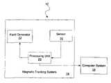
- FIG. 1is a block diagram of a coordinate measurement system.
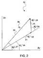
- FIG. 2is a phasor diagram including an undisturbed phasor, a disturbed phasor, and an eddy current phasor.
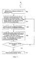
- FIG. 3is a flow chart of a signal compensation process.
- FIG. 4shows experimental results, used for determining ⁇ E , when a stainless steel ring is moved in the vicinity of the system of FIG. 1 .
- FIG. 5shows experimental values of ⁇ for the third and fifth harmonics when a stainless steel ring is used to disturb the signal of a stationary sensor.
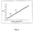
- FIG. 6shows experimental values of ⁇ ( ⁇ ) as a function of frequency for a sensor disturbed by a stainless steel ring.
- FIG. 7is a flow chart of a process to determine an asymptotic undisturbed phase.
- FIG. 8shows an experimental result of the eddy current compensation.
- FIG. 9shows an experimental result of the eddy current compensation.
- FIG. 10is a flow chart of a process to determine the presence of a disturbance based on a chi-squared value.
- FIG. 11is a flow chart of a signal compensation process.
- a coordinate measurement system 10includes a magnetic tracking system 14 having one or more sensors 16 .
- Magnetic tracking systemsalso referred to as coordinate measurement systems
- are susceptible to distortionsalso referred to as disturbances
- eddy currentsdue to eddy currents resulting from the presence of conductive materials in or near the sensor 16 and/or the field generator 12 .
- conductive materialsinclude metals (e.g. stainless steel), carbon fiber, and certain conductive plastics.
- the electromagnetic coupling that generates eddy currentsis dependent on the frequency of a transmitted AC magnetic field.
- eddy currentsare phase shifted with respect to the magnetic tracker source drive current that generates the magnetic field.
- the magnetic tracking systemincludes a field generator 12 that generates an input signal having two or more frequency components.
- the lowest of these frequency componentsis termed the fundamental frequency.
- a typical fundamental frequencymight be 1000 Hz.
- Additional frequency componentscould be harmonics of the fundamental frequency, or could be other non-harmonic frequencies.
- waveforms input by the signal inputinclude a square wave, a triangular wave, a sawtooth wave (e.g. ramp), a sinusoidal wave, a chirped wave, a multiple frequency waveform of any kind, or any combination of these.
- a computer system 18 or other computational unitanalyzes the position indication signals generated at multiple frequencies. Based on the position indication signals, computer system 18 calculates the eddy current phase and amplitude and compensates the position indication to remove the measurement error induced by the eddy current.
- a graphical representation 30 of the undisturbed phasor 31 , disturbed or total phasor 32 , and eddy current phasor 33is shown.
- Each phasoris represented by an amplitude (A) and a phase ( ⁇ ).
- the undisturbed phasor 31is represented as an undisturbed amplitude (A U ) 34 and an undisturbed phase ( ⁇ U ) 35
- the disturbed or total phasor 32is represented as a disturbed or total amplitude (A T ) 36 and a disturbed or total phase ( ⁇ T ) 37
- the eddy current phasor 33is represented as an eddy current amplitude (A E ) 38 and an eddy current phase ( ⁇ E ) 39
- the disturbed or total phasor 32is the vector sum of the undisturbed phasor 31 and the eddy current phasor 33 .
- the systemuses values of A U to calculate position indications. This is because the underlying field model used for the position fit is based on the undisturbed fields.
- a process 40 to provide compensation to the disturbed signalis shown.
- the eddy current amplitude and phasecan be calculated and removed from the disturbed phasor 32 leaving the undisturbed phasor 31 .
- the processinvolves two stages. In the first stage (steps 41 , 42 , and 43 ), a given conductive object is characterized by introducing it into the field (step 41 ) and collecting disturbed signal measurements (step 42 ). At the time of characterizing a conductive object, A U and ⁇ U are known values and can therefore be used, along with the disturbed data, to determine the eddy current phase (step 43 ). Details of step 43 are given below.
- the second stage of process 40(steps 44 , 45 , 46 , and 47 ) deal with eddy current compensation during real-time collection of position indication signals (step 44 ).
- the eddy current phase ( ⁇ E ) of step 43 and the position indication signals of step 44are used as input to the compensation procedure (step 46 ) if the characterized conductive object is known to be in the field (step 45 ). Otherwise, compensation is not necessary and the process goes directly to step 47 . Details of the compensation procedure are given below.
- a graph 56displays the results of a stationary sensor when a stainless steel ring is randomly waved in the vicinity of a sensor.
- Graph 56shows the real and imaginary components of the total sensor signal (solid circles 58 ) and the undisturbed phasor 57 .
- ⁇ Eis a constant.
- ⁇ Eis a constant that depends on the driving frequency of the field generator.
- a chi-squared ( ⁇ 2 ) valuecan be calculated.
- equation (1)is solved for A E and substituted into equation (2).
- the chi-squared valueis defined as follows:
- equation (3) and equation (4)the measurement uncertainties ⁇ j have been set to ⁇ for simplicity and N is the total number of points collected.
- the derivative of the chi-squared valueis calculated and used to determine a minimizing condition as shown in equations (5-9).
- a closed form solution as shown abovemay not exist. If a closed form solution does not exist (or is not readily known), the equations can be solved using a numerical method. For example, the equations could be solved using the Levenberg-Marquardt method.
- the eddy current phase ( ⁇ E )is a constant. However, for more complex objects the eddy current phase ( ⁇ E ) may not be constant.
- the eddy current phase ( ⁇ E ) for complex objectsoften varies depending on the position and the orientation of the distorter. In situations where the eddy current phase varies, the system utilizes a ratio of eddy current phases at different frequencies, as described below in equations (10-14).
- the eddy current phase ( ⁇ E ) relative to the sensor phasecan be written in terms of the inductance and resistance of the distorting object.
- the inductance and resistance of an objectare material constants and do not generally depend on the frequency.
- the eddy current phasecan be defined as follows:
- ⁇ E ⁇ ( ⁇ )⁇ 2 - arc ⁇ ⁇ tan ⁇ ( ⁇ ⁇ ⁇ L R ) ( 10 )
- the eddy current phase of a given harmonic frequencycan be related to the eddy current phase of the fundamental frequency (or another harmonic) in terms of the harmonic index, where the harmonic index (i) equals 1, 2, 3, . . . , N.
- the eddy current phase as a function of the harmonicis as follows:
- the eddy current phase of higher order harmonicscan be related to the eddy current phase of the first harmonic using the following ratio:
- the ratio relating the eddy current phases of two signalscan be further generalized to any pair of harmonic or non-harmonic frequencies.
- This continuous form of ⁇can be normalized to a particular frequency ⁇ n and written as follows:
- ⁇ ( ⁇ )The value of ⁇ ( ⁇ ) is used when solving a set of equations for two disturbed phasors.
- the compensation procedureuses the phasors for the first and third harmonic.
- the undisturbed phase of each sensor signalmust be input. It is generally assumed in the literature that ⁇ Ui is a constant throughout the measurement volume.
- the undisturbed phasecan be a function of sensor position and orientation (pose). For example, sensor poses for which the signal amplitude is small have different phase values than the “expected” large amplitude values (also referred to asymptotic phase values). Therefore, the undisturbed phase is known to high precision if both the sensor pose is known and a model for the phase exists.
- an iterative processallows the compensation process to determine the actual undisturbed phase starting with asymptotic phase values, for large sensor signals.
- the solution for ⁇ Ui at each iterationcan be used as a phase input for the eddy current compensation algorithm.
- the asymptotic values of the undisturbed phasescan be determined at the time of system characterization. In a first order compensation scheme only the asymptotic ⁇ Ui values are used.
- a process 61 for measuring the amplitude and phase of a disturbed sensoris described.
- a compensated value for the amplitude of the disturbed sensoris calculated (step 64 ).
- Inputs to this calculationinclude the disturbed amplitude, the disturbed phase, and the undisturbed asymptotic phase.
- Process 40describes a compensation method that can be used in step 64 and an alternative compensation method is described below.
- the corrected amplitude and phase valuesare used to determine the-position of the sensor (step 66 ). If a model exists for the sensor phases in an undisturbed field, the position calculated in step 66 is used to determine a new value for the undisturbed phase (step 68 ).
- Process 61determines if position fit convergence criteria are met (step 70 ). If the criteria are met, the calculated position is accepted and the process outputs a position indication signal (step 72 ). If the criteria are not met, process 61 returns to calculating a compensated value with the new asymptotic phase. This process repeats until the compensation criteria are met (step 70 ).
- a T and ⁇ Tare the total amplitude and phase of a sensor signal
- ⁇ Uis a quantity that can be determined at the time of characterization of a system
- the undisturbed phasemay drift or vary during the lifetime of a system, and can be re-determined or refined real-time using an iterative process.
- the values of F ican be determined using Fourier analysis. In general, however, sensor waveforms are complex and the F i values must be determined at the time of system characterization. It is assumed that the F i values do not depend on sensor position and/or orientation (this can be verified at the time of system characterization).
- the value of ⁇ i calculated using equation (13) (or ⁇ ( ⁇ ) using equation (14))expresses the eddy current phase of higher-order harmonics in terms of the eddy current phase of the first harmonic.
- equations (15-18)can be written in terms of four unknowns, namely: A U1 , A E1 , A E3 , and ⁇ E1 .
- a numerical methodcan be used to solve this system of equations.
- the data used as input to the modelincludes the real and imaginary components of the first and third harmonics of the total sensor signal.
- FIGS. 8 and 9show graphical representations of exemplary results from the eddy current compensation procedure. The results shown in these figures are for a field generator coil driven with a waveform having a fundamental frequency of about 3 kHz and a third harmonic of about 9 kHz. Higher order harmonics were present but were not used in the compensation scheme.
- FIG. 8the signal strength of a stationary sensor 84 is disturbed as a large stainless steel ring is moved into the vicinity of the field generating coil and sensor.
- the solid circles 84represent the signal before compensation and the open triangles 86 represent the signal after compensation.
- FIG. 9the signal strength of a stationary sensor is disturbed as a stainless steel plate moved into and out of the vicinity of the field generating coil and sensor.
- the solid circles 94represent the signal before compensation and the open triangles 96 represent the signal after compensation.
- a numerical methodcan be used to solve the above identified set of equations, however, a closed form solution does exist and may be used.
- the amplitude of the fundamental harmonic A U1can be represented as:
- harmonic frequencieshave been used to perform signal compensation
- the processcan be generalized to use any pair of frequencies (harmonic or non-harmonic frequencies).
- the presence of conductive objectscan also be detected by monitoring the ratio A T3 /A T1 and noting deviations from F 3 .
- ⁇ Uideviations from ⁇ Ui for large amplitude signals and regard phase changes to be associated with the presence of conductive objects.
- the real and imaginary components at each frequencyare monitored. Any number of mathematical techniques can then be used to differentiate between real and imaginary components in undisturbed and disturbed environments.
- ⁇ ij ⁇ ⁇ ⁇ ( ⁇ i )⁇ i ⁇ j ( 29 )
- Nis the total number of frequencies for which measurements are performed.
- These indicescan be any frequency and are not necessarily harmonic labels.
- the exact nature of the frequency spectrumdepends on the hardware of the system and on the waveform driving the field generator coils.
- the j th frequencyis used as a “normalization” frequency (labeled as 1 in equation (13) for example)
- Equation (27)can also be generalized to any pair of frequencies as follows:
- a complex polynomialcan be fit to a characteristic undisturbed sensor signal. Changes in the expected polynomial coefficients of subsequent measurements can be used to indicate the presence of conductive objects. Adjustments to these polynomial coefficients can then be made to compensate for any distortions of a disturbed frequency function. A proper propagation of errors for the real and imaginary values of equations (30) and (31) can also be performed to account for small amplitude signals and measurement uncertainties.
- the signal of the j th frequencycan be corrected based on the real and imaginary values of the i th frequency.
- Each j th frequencytherefore has N ⁇ 1 corrected values, from which one can calculate a weighted average amplitude, S j , (or real and imaginary components) and standard deviation ⁇ S j (e.g. uncertainty).
- the next step in this compensation procedureis to calculate a ⁇ 2 value as follows:
- ⁇is the amplitude used in a position fit
- S jis the expected and normalized amplitude, for frequency j of an undisturbed frequency function, obtained from a field generator characterization process (in an undisturbed environment). From the minimizing condition
- the desired amplitude ‘ ⁇ ’can be determined as follows:
- ⁇ 2 valuecan also be used to detect the presence of conductive objects. This is done by calculating ‘ ⁇ ’ for a set of frequency amplitudes (or real and imaginary signal components) that have not been corrected. The resulting value of ‘ ⁇ ’ is then substituted into equation (32) and a ⁇ 2 value is computed.
- a process 100 for eddy current detectionis achieved through monitoring the value of ⁇ 2 .
- Appropriate thresholdscan be set on ⁇ 2 to indicate different levels of distortion.
- Process 100is a two stage process. In the first stage (steps 102 and 104 ) the compensation system measures the characteristic frequency function of a magnetic tracking system in an undisturbed field (step 102 ) and normalizes the function (step 104 ). For example, the function can be normalized by setting the area under the function to unity. This stage can be achieved during the time of system characterization.
- the second stage of process 100(steps 108 , 110 , 112 , 114 , and 116 ) occurs when the system is in real-time operation and a disturbance is near the system.
- the systemperforms a frequency sweep (step 108 ) and measures a real-time, and possibly disturbed, frequency function (step 110 ).
- the real-time frequency functionis then compared to the undisturbed, normalized frequency function and the amplitude (‘ ⁇ ’) is calculated according to equation (34) (step 112 ).
- the calculated amplitudeis substituted into equation (32) and a value for ⁇ 2 is calculated (step 114 ).
- the ⁇ 2 valueis used to determine the extent of the disturbance to the system (step 116 ). In general, a small value of ⁇ 2 indicates a small disturbance and a large value of ⁇ 2 indicates a large disturbance.
- a process 200describes a method for determining position indication values. This process begins with eddy current detection(step 202 ), for example, process 100 . If eddy currents are detected then a compensation (step 204 ) is performed prior to calculating position indication values (step 206 ), otherwise the process can proceed immediately to calculating position indication values (step 206 )
- Multiple field generator-coilsmay be included in a detection scheme. Multiple coils provide the advantage of increased sensitivity and redundancy. The presence of conductive objects can cause a signal disturbance due to coupling to one or more of the field generator and/or sensor coils.
- the ⁇ 2 valuecan also be used to aid in “tuning” the system to a particular frequency range such that sensitivity to different types of conductive objects is obtained. For example, stainless steel objects are often more easily detected in a mid-frequency range while aluminum objects are more easily detected in a low-frequency range. Other factors such as the geometry of the object can also affect the region of sensitivity. Once the region of sensitivity has been determined for a particular conductive object, equation (34) can be used in the less sensitive regions (e.g. low-frequency ranges) to obtain a value of ‘ ⁇ ’. The motivation for doing this comes from the realization that conductive objects can be modeled as low-pass R-L circuits (i.e. filters).
Landscapes
- Health & Medical Sciences (AREA)
- Life Sciences & Earth Sciences (AREA)
- Engineering & Computer Science (AREA)
- Physics & Mathematics (AREA)
- General Health & Medical Sciences (AREA)
- Surgery (AREA)
- Biomedical Technology (AREA)
- Heart & Thoracic Surgery (AREA)
- Medical Informatics (AREA)
- Molecular Biology (AREA)
- Animal Behavior & Ethology (AREA)
- Public Health (AREA)
- Veterinary Medicine (AREA)
- Pathology (AREA)
- Biophysics (AREA)
- Nuclear Medicine, Radiotherapy & Molecular Imaging (AREA)
- Human Computer Interaction (AREA)
- General Physics & Mathematics (AREA)
- Robotics (AREA)
- Chemical & Material Sciences (AREA)
- Chemical Kinetics & Catalysis (AREA)
- Analytical Chemistry (AREA)
- Biochemistry (AREA)
- Electrochemistry (AREA)
- Immunology (AREA)
- Radiology & Medical Imaging (AREA)
- Signal Processing (AREA)
- High Energy & Nuclear Physics (AREA)
- Condensed Matter Physics & Semiconductors (AREA)
- Investigating Or Analyzing Materials By The Use Of Magnetic Means (AREA)
- Measurement Of Length, Angles, Or The Like Using Electric Or Magnetic Means (AREA)
- Geophysics And Detection Of Objects (AREA)
Abstract
Description
x=ReT=AUcos(φU)+AEcos(φU+φE) (1)
y=ImT=AUsin(φU)+AEsin(φU+φE) (2)
Substituting the χ2equation, taking the derivative, and solving for tan(φU+φE) results in the equation below:
Since magnetic tracking systems often include multiple (e.g., 4, 8, 10) field generator coils, it may be advantageous to calculate φEusing data gathered simultaneously from the multiple coils. However, when data is gathered from multiple coils, a closed form solution as shown above may not exist. If a closed form solution does not exist (or is not readily known), the equations can be solved using a numerical method. For example, the equations could be solved using the Levenberg-Marquardt method.
where ω is the angular frequency (i.e., ω=2πf). The eddy current phase of a given harmonic frequency can be related to the eddy current phase of the fundamental frequency (or another harmonic) in terms of the harmonic index, where the harmonic index (i) equals 1, 2, 3, . . . , N. The eddy current phase as a function of the harmonic is as follows:
where the angular frequency of the harmonic is defined as the harmonic index multiplied by the fundamental harmonic value or
ωi=iωl. (12)
This expression is confirmed experimentally as shown in
This generalization is confirmed experimentally as shown in
ReT1=AT1cos(φT1)=AU1cos(φU1)+AE1cos(φU1+φE1) (15)
ImT1=AT1sin(φT1)=AU1sin(φU1)+AE1sin(φU1+φE1) (16)
The real and imaginary components of the third harmonic are as follows:
ReT3=AT3cos(φT3)=AU3cos(φU3)+AE3cos(φU3+φE3) (17)
ImT3=AT3sin(φT3)=AU3sin(φU3)+AE3sin(φU3+φE3) (18)
This can be rewritten as:
where the indices i=1, . . . , N and j=1, . . . , N label the frequencies for which sensor amplitudes have been measured, and N is the total number of frequencies for which measurements are performed. These indices can be any frequency and are not necessarily harmonic labels. The exact nature of the frequency spectrum depends on the hardware of the system and on the waveform driving the field generator coils. The jthfrequency is used as a “normalization” frequency (labeled as 1 in equation (13) for example)
for all i. Although equation (30) is explicitly written for pairs of frequencies, any number of relevant mathematical formulations that are stated in terms of the real and imaginary values can be used for compensation. For example, for continuous frequency functions, a complex polynomial can be fit to a characteristic undisturbed sensor signal. Changes in the expected polynomial coefficients of subsequent measurements can be used to indicate the presence of conductive objects. Adjustments to these polynomial coefficients can then be made to compensate for any distortions of a disturbed frequency function. A proper propagation of errors for the real and imaginary values of equations (30) and (31) can also be performed to account for small amplitude signals and measurement uncertainties.
where ‘α’ is the amplitude used in a position fit and
the desired amplitude ‘α’ can be determined as follows:
The χ2value can also be used to detect the presence of conductive objects. This is done by calculating ‘α’ for a set of frequency amplitudes (or real and imaginary signal components) that have not been corrected. The resulting value of ‘α’ is then substituted into equation (32) and a χ2value is computed.
Claims (15)
Priority Applications (1)
| Application Number | Priority Date | Filing Date | Title |
|---|---|---|---|
| US11/331,518US7353125B2 (en) | 2003-04-17 | 2006-01-13 | Eddy current detection and compensation |
Applications Claiming Priority (3)
| Application Number | Priority Date | Filing Date | Title |
|---|---|---|---|
| US46357603P | 2003-04-17 | 2003-04-17 | |
| US10/824,846US7783441B2 (en) | 2003-04-17 | 2004-04-15 | Eddy current detection and compensation |
| US11/331,518US7353125B2 (en) | 2003-04-17 | 2006-01-13 | Eddy current detection and compensation |
Related Parent Applications (1)
| Application Number | Title | Priority Date | Filing Date |
|---|---|---|---|
| US10/824,846DivisionUS7783441B2 (en) | 2003-04-17 | 2004-04-15 | Eddy current detection and compensation |
Publications (2)
| Publication Number | Publication Date |
|---|---|
| US20060116832A1 US20060116832A1 (en) | 2006-06-01 |
| US7353125B2true US7353125B2 (en) | 2008-04-01 |
Family
ID=33300081
Family Applications (4)
| Application Number | Title | Priority Date | Filing Date |
|---|---|---|---|
| US10/824,846Active2026-11-03US7783441B2 (en) | 2003-04-17 | 2004-04-15 | Eddy current detection and compensation |
| US11/332,390Expired - LifetimeUS7469187B2 (en) | 2003-04-17 | 2006-01-13 | Eddy current detection and compensation |
| US11/331,518Expired - LifetimeUS7353125B2 (en) | 2003-04-17 | 2006-01-13 | Eddy current detection and compensation |
| US12/861,487Expired - LifetimeUS7957925B2 (en) | 2003-04-17 | 2010-08-23 | Eddy current detection and compensation |
Family Applications Before (2)
| Application Number | Title | Priority Date | Filing Date |
|---|---|---|---|
| US10/824,846Active2026-11-03US7783441B2 (en) | 2003-04-17 | 2004-04-15 | Eddy current detection and compensation |
| US11/332,390Expired - LifetimeUS7469187B2 (en) | 2003-04-17 | 2006-01-13 | Eddy current detection and compensation |
Family Applications After (1)
| Application Number | Title | Priority Date | Filing Date |
|---|---|---|---|
| US12/861,487Expired - LifetimeUS7957925B2 (en) | 2003-04-17 | 2010-08-23 | Eddy current detection and compensation |
Country Status (8)
| Country | Link |
|---|---|
| US (4) | US7783441B2 (en) |
| EP (3) | EP2052681B1 (en) |
| JP (1) | JP2006523473A (en) |
| KR (1) | KR20060023960A (en) |
| CN (3) | CN101496724B (en) |
| AT (1) | ATE536802T1 (en) |
| CA (2) | CA2756830C (en) |
| WO (1) | WO2004091391A1 (en) |
Cited By (34)
| Publication number | Priority date | Publication date | Assignee | Title |
|---|---|---|---|---|
| US20080118135A1 (en)* | 2006-11-10 | 2008-05-22 | Superdimension, Ltd. | Adaptive Navigation Technique For Navigating A Catheter Through A Body Channel Or Cavity |
| US20080167639A1 (en)* | 2007-01-08 | 2008-07-10 | Superdimension Ltd. | Methods for localized intra-body treatment of tissue |
| US20080262297A1 (en)* | 2004-04-26 | 2008-10-23 | Super Dimension Ltd. | System and Method for Image-Based Alignment of an Endoscope |
| US20090156951A1 (en)* | 2007-07-09 | 2009-06-18 | Superdimension, Ltd. | Patient breathing modeling |
| US20100008555A1 (en)* | 2008-05-15 | 2010-01-14 | Superdimension, Ltd. | Automatic Pathway And Waypoint Generation And Navigation Method |
| US20100013812A1 (en)* | 2008-07-18 | 2010-01-21 | Wei Gu | Systems for Controlling Computers and Devices |
| US20100034449A1 (en)* | 2008-06-06 | 2010-02-11 | Superdimension, Ltd. | Hybrid Registration Method |
| US20100198015A1 (en)* | 2003-09-15 | 2010-08-05 | Benny Greenburg | System Of Accessories For Use With Bronchoscopes |
| US7998062B2 (en) | 2004-03-29 | 2011-08-16 | Superdimension, Ltd. | Endoscope structures and techniques for navigating to a target in branched structure |
| US8428328B2 (en) | 2010-02-01 | 2013-04-23 | Superdimension, Ltd | Region-growing algorithm |
| US8473032B2 (en) | 2008-06-03 | 2013-06-25 | Superdimension, Ltd. | Feature-based registration method |
| US8611984B2 (en) | 2009-04-08 | 2013-12-17 | Covidien Lp | Locatable catheter |
| US8641210B2 (en) | 2011-11-30 | 2014-02-04 | Izi Medical Products | Retro-reflective marker including colored mounting portion |
| US8661573B2 (en) | 2012-02-29 | 2014-03-04 | Izi Medical Products | Protective cover for medical device having adhesive mechanism |
| US8764725B2 (en) | 2004-02-09 | 2014-07-01 | Covidien Lp | Directional anchoring mechanism, method and applications thereof |
| US8905920B2 (en) | 2007-09-27 | 2014-12-09 | Covidien Lp | Bronchoscope adapter and method |
| US8932207B2 (en) | 2008-07-10 | 2015-01-13 | Covidien Lp | Integrated multi-functional endoscopic tool |
| US9575140B2 (en) | 2008-04-03 | 2017-02-21 | Covidien Lp | Magnetic interference detection system and method |
| US10418705B2 (en) | 2016-10-28 | 2019-09-17 | Covidien Lp | Electromagnetic navigation antenna assembly and electromagnetic navigation system including the same |
| US10426555B2 (en) | 2015-06-03 | 2019-10-01 | Covidien Lp | Medical instrument with sensor for use in a system and method for electromagnetic navigation |
| US10446931B2 (en) | 2016-10-28 | 2019-10-15 | Covidien Lp | Electromagnetic navigation antenna assembly and electromagnetic navigation system including the same |
| US10478254B2 (en) | 2016-05-16 | 2019-11-19 | Covidien Lp | System and method to access lung tissue |
| US10517505B2 (en) | 2016-10-28 | 2019-12-31 | Covidien Lp | Systems, methods, and computer-readable media for optimizing an electromagnetic navigation system |
| US10582834B2 (en) | 2010-06-15 | 2020-03-10 | Covidien Lp | Locatable expandable working channel and method |
| US10615500B2 (en) | 2016-10-28 | 2020-04-07 | Covidien Lp | System and method for designing electromagnetic navigation antenna assemblies |
| US10638952B2 (en) | 2016-10-28 | 2020-05-05 | Covidien Lp | Methods, systems, and computer-readable media for calibrating an electromagnetic navigation system |
| US10722311B2 (en) | 2016-10-28 | 2020-07-28 | Covidien Lp | System and method for identifying a location and/or an orientation of an electromagnetic sensor based on a map |
| US10746815B2 (en) | 2016-12-22 | 2020-08-18 | Microsoft Technology Licensing, Llc | Magnetic interference detection and correction |
| US10751126B2 (en) | 2016-10-28 | 2020-08-25 | Covidien Lp | System and method for generating a map for electromagnetic navigation |
| US10792106B2 (en) | 2016-10-28 | 2020-10-06 | Covidien Lp | System for calibrating an electromagnetic navigation system |
| US10952593B2 (en) | 2014-06-10 | 2021-03-23 | Covidien Lp | Bronchoscope adapter |
| WO2021123957A1 (en)* | 2019-12-16 | 2021-06-24 | Biosense Webster (Israel) Ltd. | Sparse calibration of magnetic field created by coils in metal-rich environment |
| US11194071B2 (en) | 2017-07-19 | 2021-12-07 | Intricon Corporation | Interconnect ring for microminiature electrical coil |
| US11219489B2 (en) | 2017-10-31 | 2022-01-11 | Covidien Lp | Devices and systems for providing sensors in parallel with medical tools |
Families Citing this family (54)
| Publication number | Priority date | Publication date | Assignee | Title |
|---|---|---|---|---|
| US7783441B2 (en) | 2003-04-17 | 2010-08-24 | Northern Digital Inc. | Eddy current detection and compensation |
| US7292948B2 (en)* | 2004-04-30 | 2007-11-06 | Alken Inc. | Magnetic position and orientation measurement system with eddy current distortion compensation |
| US20080006280A1 (en)* | 2004-07-20 | 2008-01-10 | Anthony Aliberto | Magnetic navigation maneuvering sheath |
| US20060264732A1 (en)* | 2005-05-05 | 2006-11-23 | Chunwu Wu | System and method for electromagnetic navigation in the vicinity of a metal object |
| US20060255795A1 (en)* | 2005-05-13 | 2006-11-16 | Higgins Robert F | Six-degree-of-freedom, integrated-coil AC magnetic tracker |
| US8000772B2 (en)* | 2005-10-19 | 2011-08-16 | Biosense Webster, Inc. | Metal immunity in a reverse magnetic system |
| US7471202B2 (en) | 2006-03-29 | 2008-12-30 | General Electric Co. | Conformal coil array for a medical tracking system |
| US7532997B2 (en) | 2006-04-17 | 2009-05-12 | General Electric Company | Electromagnetic tracking using a discretized numerical field model |
| US8082020B2 (en)* | 2006-08-07 | 2011-12-20 | Biosense Webster, Inc. | Distortion-immune position tracking using redundant magnetic field measurements |
| US8326402B2 (en)* | 2006-08-21 | 2012-12-04 | Biosense Webster, Inc. | Distortion-immune position tracking using frequency extrapolation |
| DE102007012361B4 (en)* | 2007-03-14 | 2016-09-22 | Siemens Healthcare Gmbh | Method for determining the position of a medical instrument and position-determining device |
| DE102007023059A1 (en) | 2007-05-16 | 2008-12-04 | Siemens Ag | Miniaturized device |
| US8391952B2 (en)* | 2007-10-11 | 2013-03-05 | General Electric Company | Coil arrangement for an electromagnetic tracking system |
| FR2946154B1 (en) | 2009-05-26 | 2011-07-01 | Commissariat Energie Atomique | DETECTION METHOD AND DETECTOR DETECTOR, METHOD AND SYSTEM FOR LOCALIZATION USING THE SAME. |
| US8600480B2 (en)* | 2009-12-31 | 2013-12-03 | Mediguide Ltd. | System and method for assessing interference to a signal caused by a magnetic field |
| DE102011013398A1 (en) | 2010-03-10 | 2011-09-15 | Northern Digital Inc. | Magnetic location system |
| US8806832B2 (en) | 2011-03-18 | 2014-08-19 | Inotec Global Limited | Vertical joint system and associated surface covering system |
| JP5427842B2 (en) | 2011-06-30 | 2014-02-26 | 日立オートモティブシステムズ株式会社 | Rotation angle measuring device, control device, and rotating machine system using them |
| EP2915157B1 (en) | 2012-10-30 | 2019-05-08 | Truinject Corp. | System for injection training |
| US9792836B2 (en) | 2012-10-30 | 2017-10-17 | Truinject Corp. | Injection training apparatus using 3D position sensor |
| WO2014196326A1 (en)* | 2013-06-07 | 2014-12-11 | オリンパスメディカルシステムズ株式会社 | Position detection device and position detection method for medical equipment, and endoscopic device |
| WO2015109251A1 (en) | 2014-01-17 | 2015-07-23 | Truinject Medical Corp. | Injection site training system |
| US10290231B2 (en) | 2014-03-13 | 2019-05-14 | Truinject Corp. | Automated detection of performance characteristics in an injection training system |
| CN107205784B (en) | 2014-07-03 | 2021-03-09 | 圣犹达医疗用品国际控股有限公司 | Local magnetic field generator |
| US10588541B2 (en) | 2014-07-15 | 2020-03-17 | General Electric Company | Magnetic tracker system and method for use for surgical navigation |
| KR20170102233A (en) | 2014-12-01 | 2017-09-08 | 트루인젝트 코프 | Injection training tool emitting omnidirectional light |
| US10285760B2 (en) | 2015-02-04 | 2019-05-14 | Queen's University At Kingston | Methods and apparatus for improved electromagnetic tracking and localization |
| FR3039284B1 (en) | 2015-07-20 | 2017-08-25 | Commissariat Energie Atomique | ELECTROMAGNETIC POSITION TRACKING SYSTEM |
| JP6064109B1 (en)* | 2015-07-24 | 2017-01-18 | オリンパス株式会社 | Position detection system and guidance system |
| WO2017070391A2 (en) | 2015-10-20 | 2017-04-27 | Truinject Medical Corp. | Injection system |
| WO2017094415A1 (en) | 2015-12-02 | 2017-06-08 | オリンパス株式会社 | Position detection system and position detection method |
| WO2017094405A1 (en)* | 2015-12-02 | 2017-06-08 | オリンパス株式会社 | Position detection system and position detection method |
| WO2017151441A2 (en) | 2016-02-29 | 2017-09-08 | Truinject Medical Corp. | Cosmetic and therapeutic injection safety systems, methods, and devices |
| WO2017151963A1 (en) | 2016-03-02 | 2017-09-08 | Truinject Madical Corp. | Sensory enhanced environments for injection aid and social training |
| JP6153693B1 (en)* | 2016-03-04 | 2017-06-28 | オリンパス株式会社 | Guide device and capsule medical device guide system |
| WO2017149834A1 (en)* | 2016-03-04 | 2017-09-08 | オリンパス株式会社 | Guiding device and capsule-medical-device guiding system |
| WO2017196371A1 (en) | 2016-05-13 | 2017-11-16 | Halliburton Energy Services, Inc. | Electromagnetic (em) defect detection methods and systems employing deconvolved raw measurements |
| JP6931393B2 (en)* | 2016-11-21 | 2021-09-01 | セント・ジュード・メディカル・インターナショナル・ホールディング・エスエーアールエルSt. Jude Medical International Holding S.a,r.l. | Perspective transparent magnetic field generator |
| US10269266B2 (en) | 2017-01-23 | 2019-04-23 | Truinject Corp. | Syringe dose and position measuring apparatus |
| JP6880861B2 (en)* | 2017-03-15 | 2021-06-02 | オムロン株式会社 | Proximity sensor and detection method |
| FR3069068B1 (en) | 2017-07-17 | 2019-08-23 | Sysnav | METHOD FOR LOCATING A EVOLVING OBJECT IN A MAGNETIC FIELD GENERATED BY A SET OF AT LEAST THREE MAGNETIC GENERATORS |
| CN107677976B (en)* | 2017-09-26 | 2019-07-16 | 中国科学院武汉物理与数学研究所 | An adaptive nuclear magnetic resonance gradient pre-emphasis waveform generating device and method |
| FR3073629B1 (en)* | 2017-11-16 | 2021-05-28 | Minmaxmedical | COMPENSATION PROCESS FOR A MAGNETIC LOCATOR, LOCATOR AND COMPUTER PROGRAM |
| CN109975397B (en)* | 2017-12-27 | 2022-06-28 | 核动力运行研究所 | Multi-frequency eddy current complex signal-based high-fidelity extraction method for damage information of heat transfer pipe |
| FR3088820B1 (en) | 2018-11-23 | 2022-08-12 | Modjaw | METHOD FOR ANIMATING MODELS OF THE MANDIBULAR AND MAXILLARY ARCHES OF A PATIENT IN A CORRECTED INTERMAXILLARY RELATION |
| CN109782196B (en)* | 2018-12-25 | 2021-06-22 | 中国船舶重工集团公司第七一0研究所 | Interference magnetic field compensation method |
| KR102052849B1 (en)* | 2019-03-14 | 2019-12-04 | 에디웍스(주) | APPARATUS FOR DETECTING RAIL DEFECT BY USING MULTI-CHANNEL EDDY CURRENT SENSOR AND Sensor calibrating METHOD THEREOF AND RAIL DEFECT DETECTING METHOD |
| US11547495B2 (en) | 2019-04-26 | 2023-01-10 | Globus Medical, Inc. | System and method for reducing interference in positional sensors for robotic surgery |
| US20210333228A1 (en)* | 2020-04-24 | 2021-10-28 | Kla Corporation | Micro-Four-Point Metrology of Joule-Heating-Induced Modulation of Test Sample Properties |
| CN115436855B (en)* | 2021-06-02 | 2025-05-30 | 上海联影医疗科技股份有限公司 | Eddy current correction method, magnetic resonance image correction method, device, equipment and medium |
| CN113769274B (en)* | 2021-10-26 | 2023-08-22 | 深圳奥派森生物电磁科技有限公司 | Tumor treatment equipment by magnetic field |
| EP4201360A1 (en) | 2021-12-27 | 2023-06-28 | MinMaxMedical | Electromagnetic localization system |
| EP4201361A1 (en) | 2021-12-27 | 2023-06-28 | MinMaxMedical | Real-time electromagnetic localization system |
| US12310676B2 (en) | 2022-11-22 | 2025-05-27 | Medtronic Navigation, Inc. | Navigation at ultra low to high frequencies |
Citations (11)
| Publication number | Priority date | Publication date | Assignee | Title |
|---|---|---|---|---|
| EP0228056A2 (en) | 1986-01-03 | 1987-07-08 | General Electric Company | A method for magnetic field gradient eddy current compensation |
| US4829250A (en) | 1988-02-10 | 1989-05-09 | Honeywell, Inc. | Magnetic direction finding device with improved accuracy |
| US5629626A (en)* | 1994-07-12 | 1997-05-13 | Geo-Centers, Inc. | Apparatus and method for measuring buried ferromagnetic objects with a high accuracy of position and in synchronization with a sync pulse provided by a global positioning system |
| US5767669A (en) | 1996-06-14 | 1998-06-16 | Ascension Technology Corporation | Magnetic field position and orientation measurement system with dynamic eddy current rejection |
| EP0993804A1 (en) | 1998-10-15 | 2000-04-19 | Biosense, Inc. | Method and system for tracking an object |
| US6172499B1 (en) | 1999-10-29 | 2001-01-09 | Ascension Technology Corporation | Eddy current error-reduced AC magnetic position measurement system |
| WO2002008793A1 (en) | 2000-07-26 | 2002-01-31 | Northern Digital Inc. | Method for determining the position of a sensor element |
| EP1203560A2 (en) | 2000-10-31 | 2002-05-08 | Biosense, Inc. | Method and apparatus for tracking an object, in particular a catheter, using energy fields |
| US6427079B1 (en) | 1999-08-09 | 2002-07-30 | Cormedica Corporation | Position and orientation measuring with magnetic fields |
| US6624626B2 (en) | 1999-11-01 | 2003-09-23 | Polhemus Inc. | Method and apparatus for electromagnetic position and orientation tracking with distortion compensation employing modulated signal |
| US20050222625A1 (en)* | 2004-03-30 | 2005-10-06 | Shlomo Laniado | Method and apparatus for non-invasive therapy of cardiovascular ailments using weak pulsed electromagnetic radiation |
Family Cites Families (7)
| Publication number | Priority date | Publication date | Assignee | Title |
|---|---|---|---|---|
| JP3849250B2 (en)* | 1997-09-30 | 2006-11-22 | 株式会社島津製作所 | Magnetic 3D tracker |
| US7809421B1 (en)* | 2000-07-20 | 2010-10-05 | Biosense, Inc. | Medical system calibration with static metal compensation |
| JP4288443B2 (en)* | 2000-09-07 | 2009-07-01 | 株式会社島津製作所 | Head motion tracker and its measurement value correction method |
| JP2002111397A (en)* | 2000-09-29 | 2002-04-12 | Sony Corp | Distortion compensator and distortion compensation method |
| US6528991B2 (en)* | 2001-07-03 | 2003-03-04 | Ascension Technology Corporation | Magnetic position measurement system with field containment means |
| US7253987B1 (en)* | 2002-07-10 | 2007-08-07 | Maxtor Corporation | Disturbance signal reduction in servo systems |
| US7783441B2 (en) | 2003-04-17 | 2010-08-24 | Northern Digital Inc. | Eddy current detection and compensation |
- 2004
- 2004-04-15USUS10/824,846patent/US7783441B2/enactiveActive
- 2004-04-19CACA2756830Apatent/CA2756830C/ennot_activeExpired - Lifetime
- 2004-04-19CNCN2009100064407Apatent/CN101496724B/ennot_activeExpired - Lifetime
- 2004-04-19WOPCT/CA2004/000587patent/WO2004091391A1/enactiveApplication Filing
- 2004-04-19EPEP09153061.8Apatent/EP2052681B1/ennot_activeExpired - Lifetime
- 2004-04-19CNCN2009100064411Apatent/CN101498687B/ennot_activeExpired - Lifetime
- 2004-04-19JPJP2006504114Apatent/JP2006523473A/enactivePending
- 2004-04-19EPEP04728145Apatent/EP1613213B1/ennot_activeExpired - Lifetime
- 2004-04-19KRKR1020057019776Apatent/KR20060023960A/ennot_activeWithdrawn
- 2004-04-19CACA2521537Apatent/CA2521537C/ennot_activeExpired - Lifetime
- 2004-04-19EPEP10184092.4Apatent/EP2269507B1/ennot_activeExpired - Lifetime
- 2004-04-19CNCNB2004800098305Apatent/CN100534387C/ennot_activeExpired - Lifetime
- 2004-04-19ATAT04728145Tpatent/ATE536802T1/enactive
- 2006
- 2006-01-13USUS11/332,390patent/US7469187B2/ennot_activeExpired - Lifetime
- 2006-01-13USUS11/331,518patent/US7353125B2/ennot_activeExpired - Lifetime
- 2010
- 2010-08-23USUS12/861,487patent/US7957925B2/ennot_activeExpired - Lifetime
Patent Citations (11)
| Publication number | Priority date | Publication date | Assignee | Title |
|---|---|---|---|---|
| EP0228056A2 (en) | 1986-01-03 | 1987-07-08 | General Electric Company | A method for magnetic field gradient eddy current compensation |
| US4829250A (en) | 1988-02-10 | 1989-05-09 | Honeywell, Inc. | Magnetic direction finding device with improved accuracy |
| US5629626A (en)* | 1994-07-12 | 1997-05-13 | Geo-Centers, Inc. | Apparatus and method for measuring buried ferromagnetic objects with a high accuracy of position and in synchronization with a sync pulse provided by a global positioning system |
| US5767669A (en) | 1996-06-14 | 1998-06-16 | Ascension Technology Corporation | Magnetic field position and orientation measurement system with dynamic eddy current rejection |
| EP0993804A1 (en) | 1998-10-15 | 2000-04-19 | Biosense, Inc. | Method and system for tracking an object |
| US6427079B1 (en) | 1999-08-09 | 2002-07-30 | Cormedica Corporation | Position and orientation measuring with magnetic fields |
| US6172499B1 (en) | 1999-10-29 | 2001-01-09 | Ascension Technology Corporation | Eddy current error-reduced AC magnetic position measurement system |
| US6624626B2 (en) | 1999-11-01 | 2003-09-23 | Polhemus Inc. | Method and apparatus for electromagnetic position and orientation tracking with distortion compensation employing modulated signal |
| WO2002008793A1 (en) | 2000-07-26 | 2002-01-31 | Northern Digital Inc. | Method for determining the position of a sensor element |
| EP1203560A2 (en) | 2000-10-31 | 2002-05-08 | Biosense, Inc. | Method and apparatus for tracking an object, in particular a catheter, using energy fields |
| US20050222625A1 (en)* | 2004-03-30 | 2005-10-06 | Shlomo Laniado | Method and apparatus for non-invasive therapy of cardiovascular ailments using weak pulsed electromagnetic radiation |
Non-Patent Citations (1)
| Title |
|---|
| International Search Report, PCT/CA2004/000587, dated Aug. 23, 2004, 3 pages. |
Cited By (102)
| Publication number | Priority date | Publication date | Assignee | Title |
|---|---|---|---|---|
| US10743748B2 (en) | 2002-04-17 | 2020-08-18 | Covidien Lp | Endoscope structures and techniques for navigating to a target in branched structure |
| US8696548B2 (en) | 2002-04-17 | 2014-04-15 | Covidien Lp | Endoscope structures and techniques for navigating to a target in branched structure |
| US8696685B2 (en) | 2002-04-17 | 2014-04-15 | Covidien Lp | Endoscope structures and techniques for navigating to a target in branched structure |
| US9642514B2 (en) | 2002-04-17 | 2017-05-09 | Covidien Lp | Endoscope structures and techniques for navigating to a target in a branched structure |
| US20100198015A1 (en)* | 2003-09-15 | 2010-08-05 | Benny Greenburg | System Of Accessories For Use With Bronchoscopes |
| US9089261B2 (en) | 2003-09-15 | 2015-07-28 | Covidien Lp | System of accessories for use with bronchoscopes |
| US10383509B2 (en) | 2003-09-15 | 2019-08-20 | Covidien Lp | System of accessories for use with bronchoscopes |
| US8663088B2 (en) | 2003-09-15 | 2014-03-04 | Covidien Lp | System of accessories for use with bronchoscopes |
| US10173043B2 (en) | 2004-02-09 | 2019-01-08 | Covidien Lp | Directional anchoring mechanism, and method and applications thereof |
| US10406325B2 (en) | 2004-02-09 | 2019-09-10 | Covidien Lp | Directional anchoring mechanism, method and applications thereof |
| US8764725B2 (en) | 2004-02-09 | 2014-07-01 | Covidien Lp | Directional anchoring mechanism, method and applications thereof |
| US7998062B2 (en) | 2004-03-29 | 2011-08-16 | Superdimension, Ltd. | Endoscope structures and techniques for navigating to a target in branched structure |
| US20080262297A1 (en)* | 2004-04-26 | 2008-10-23 | Super Dimension Ltd. | System and Method for Image-Based Alignment of an Endoscope |
| US10321803B2 (en) | 2004-04-26 | 2019-06-18 | Covidien Lp | System and method for image-based alignment of an endoscope |
| US9055881B2 (en) | 2004-04-26 | 2015-06-16 | Super Dimension Ltd. | System and method for image-based alignment of an endoscope |
| US9129359B2 (en) | 2006-11-10 | 2015-09-08 | Covidien Lp | Adaptive navigation technique for navigating a catheter through a body channel or cavity |
| US11024026B2 (en) | 2006-11-10 | 2021-06-01 | Covidien Lp | Adaptive navigation technique for navigating a catheter through a body channel or cavity |
| US10346976B2 (en) | 2006-11-10 | 2019-07-09 | Covidien Lp | Adaptive navigation technique for navigating a catheter through a body channel or cavity |
| US11631174B2 (en) | 2006-11-10 | 2023-04-18 | Covidien Lp | Adaptive navigation technique for navigating a catheter through a body channel or cavity |
| US20080118135A1 (en)* | 2006-11-10 | 2008-05-22 | Superdimension, Ltd. | Adaptive Navigation Technique For Navigating A Catheter Through A Body Channel Or Cavity |
| US20080167639A1 (en)* | 2007-01-08 | 2008-07-10 | Superdimension Ltd. | Methods for localized intra-body treatment of tissue |
| US10292619B2 (en) | 2007-07-09 | 2019-05-21 | Covidien Lp | Patient breathing modeling |
| US20090156951A1 (en)* | 2007-07-09 | 2009-06-18 | Superdimension, Ltd. | Patient breathing modeling |
| US11089974B2 (en) | 2007-07-09 | 2021-08-17 | Covidien Lp | Monitoring the location of a probe during patient breathing |
| US9668639B2 (en) | 2007-09-27 | 2017-06-06 | Covidien Lp | Bronchoscope adapter and method |
| US10980400B2 (en) | 2007-09-27 | 2021-04-20 | Covidien Lp | Bronchoscope adapter and method |
| US9986895B2 (en) | 2007-09-27 | 2018-06-05 | Covidien Lp | Bronchoscope adapter and method |
| US8905920B2 (en) | 2007-09-27 | 2014-12-09 | Covidien Lp | Bronchoscope adapter and method |
| US10390686B2 (en) | 2007-09-27 | 2019-08-27 | Covidien Lp | Bronchoscope adapter and method |
| US9575140B2 (en) | 2008-04-03 | 2017-02-21 | Covidien Lp | Magnetic interference detection system and method |
| US9439564B2 (en) | 2008-05-15 | 2016-09-13 | Covidien Lp | Automatic pathway and waypoint generation and navigation method |
| US9375141B2 (en) | 2008-05-15 | 2016-06-28 | Covidien Lp | Automatic pathway and waypoint generation and navigation method |
| US20100008555A1 (en)* | 2008-05-15 | 2010-01-14 | Superdimension, Ltd. | Automatic Pathway And Waypoint Generation And Navigation Method |
| US8494246B2 (en) | 2008-05-15 | 2013-07-23 | Covidien Lp | Automatic pathway and waypoint generation and navigation method |
| US10136814B2 (en) | 2008-05-15 | 2018-11-27 | Covidien Lp | Automatic pathway and waypoint generation and navigation method |
| US8218846B2 (en) | 2008-05-15 | 2012-07-10 | Superdimension, Ltd. | Automatic pathway and waypoint generation and navigation method |
| US8473032B2 (en) | 2008-06-03 | 2013-06-25 | Superdimension, Ltd. | Feature-based registration method |
| US11074702B2 (en) | 2008-06-03 | 2021-07-27 | Covidien Lp | Feature-based registration method |
| US9659374B2 (en) | 2008-06-03 | 2017-05-23 | Covidien Lp | Feature-based registration method |
| US11783498B2 (en) | 2008-06-03 | 2023-10-10 | Covidien Lp | Feature-based registration method |
| US9117258B2 (en) | 2008-06-03 | 2015-08-25 | Covidien Lp | Feature-based registration method |
| US10096126B2 (en) | 2008-06-03 | 2018-10-09 | Covidien Lp | Feature-based registration method |
| US9271803B2 (en) | 2008-06-06 | 2016-03-01 | Covidien Lp | Hybrid registration method |
| US10478092B2 (en) | 2008-06-06 | 2019-11-19 | Covidien Lp | Hybrid registration method |
| US10285623B2 (en) | 2008-06-06 | 2019-05-14 | Covidien Lp | Hybrid registration method |
| US8452068B2 (en) | 2008-06-06 | 2013-05-28 | Covidien Lp | Hybrid registration method |
| US8467589B2 (en) | 2008-06-06 | 2013-06-18 | Covidien Lp | Hybrid registration method |
| US8218847B2 (en) | 2008-06-06 | 2012-07-10 | Superdimension, Ltd. | Hybrid registration method |
| US20100034449A1 (en)* | 2008-06-06 | 2010-02-11 | Superdimension, Ltd. | Hybrid Registration Method |
| US10674936B2 (en) | 2008-06-06 | 2020-06-09 | Covidien Lp | Hybrid registration method |
| US11931141B2 (en) | 2008-06-06 | 2024-03-19 | Covidien Lp | Hybrid registration method |
| US11234611B2 (en) | 2008-07-10 | 2022-02-01 | Covidien Lp | Integrated multi-functional endoscopic tool |
| US11241164B2 (en) | 2008-07-10 | 2022-02-08 | Covidien Lp | Integrated multi-functional endoscopic tool |
| US10912487B2 (en) | 2008-07-10 | 2021-02-09 | Covidien Lp | Integrated multi-function endoscopic tool |
| US10070801B2 (en) | 2008-07-10 | 2018-09-11 | Covidien Lp | Integrated multi-functional endoscopic tool |
| US8932207B2 (en) | 2008-07-10 | 2015-01-13 | Covidien Lp | Integrated multi-functional endoscopic tool |
| US20100013767A1 (en)* | 2008-07-18 | 2010-01-21 | Wei Gu | Methods for Controlling Computers and Devices |
| US20100013766A1 (en)* | 2008-07-18 | 2010-01-21 | Wei Gu | Methods for Controlling Computers and Devices |
| US20100013812A1 (en)* | 2008-07-18 | 2010-01-21 | Wei Gu | Systems for Controlling Computers and Devices |
| US10154798B2 (en) | 2009-04-08 | 2018-12-18 | Covidien Lp | Locatable catheter |
| US9113813B2 (en) | 2009-04-08 | 2015-08-25 | Covidien Lp | Locatable catheter |
| US8611984B2 (en) | 2009-04-08 | 2013-12-17 | Covidien Lp | Locatable catheter |
| US9042625B2 (en) | 2010-02-01 | 2015-05-26 | Covidien Lp | Region-growing algorithm |
| US10249045B2 (en) | 2010-02-01 | 2019-04-02 | Covidien Lp | Region-growing algorithm |
| US8842898B2 (en) | 2010-02-01 | 2014-09-23 | Covidien Lp | Region-growing algorithm |
| US8428328B2 (en) | 2010-02-01 | 2013-04-23 | Superdimension, Ltd | Region-growing algorithm |
| US9595111B2 (en) | 2010-02-01 | 2017-03-14 | Covidien Lp | Region-growing algorithm |
| US9836850B2 (en) | 2010-02-01 | 2017-12-05 | Covidien Lp | Region-growing algorithm |
| US10582834B2 (en) | 2010-06-15 | 2020-03-10 | Covidien Lp | Locatable expandable working channel and method |
| US8668344B2 (en) | 2011-11-30 | 2014-03-11 | Izi Medical Products | Marker sphere including edged opening to aid in molding |
| US9964649B2 (en) | 2011-11-30 | 2018-05-08 | Izi Medical Products | Packaging for retro-reflective markers |
| US8668345B2 (en) | 2011-11-30 | 2014-03-11 | Izi Medical Products | Retro-reflective marker with snap on threaded post |
| US8668343B2 (en) | 2011-11-30 | 2014-03-11 | Izi Medical Products | Reflective marker with alignment feature |
| US8668342B2 (en) | 2011-11-30 | 2014-03-11 | Izi Medical Products | Material thickness control over retro-reflective marker |
| US8646921B2 (en) | 2011-11-30 | 2014-02-11 | Izi Medical Products | Reflective marker being radio-opaque for MRI |
| US8651274B2 (en) | 2011-11-30 | 2014-02-18 | Izi Medical Products | Packaging for retro-reflective markers |
| US8641210B2 (en) | 2011-11-30 | 2014-02-04 | Izi Medical Products | Retro-reflective marker including colored mounting portion |
| US9085401B2 (en) | 2011-11-30 | 2015-07-21 | Izi Medical Products | Packaging for retro-reflective markers |
| US8672490B2 (en) | 2011-11-30 | 2014-03-18 | Izi Medical Products | High reflectivity retro-reflective marker |
| US8662684B2 (en) | 2011-11-30 | 2014-03-04 | Izi Medical Products | Radiopaque core |
| US8661573B2 (en) | 2012-02-29 | 2014-03-04 | Izi Medical Products | Protective cover for medical device having adhesive mechanism |
| US10952593B2 (en) | 2014-06-10 | 2021-03-23 | Covidien Lp | Bronchoscope adapter |
| US10426555B2 (en) | 2015-06-03 | 2019-10-01 | Covidien Lp | Medical instrument with sensor for use in a system and method for electromagnetic navigation |
| US11160617B2 (en) | 2016-05-16 | 2021-11-02 | Covidien Lp | System and method to access lung tissue |
| US11786317B2 (en) | 2016-05-16 | 2023-10-17 | Covidien Lp | System and method to access lung tissue |
| US10478254B2 (en) | 2016-05-16 | 2019-11-19 | Covidien Lp | System and method to access lung tissue |
| US10722311B2 (en) | 2016-10-28 | 2020-07-28 | Covidien Lp | System and method for identifying a location and/or an orientation of an electromagnetic sensor based on a map |
| US11759264B2 (en) | 2016-10-28 | 2023-09-19 | Covidien Lp | System and method for identifying a location and/or an orientation of an electromagnetic sensor based on a map |
| US11786314B2 (en) | 2016-10-28 | 2023-10-17 | Covidien Lp | System for calibrating an electromagnetic navigation system |
| US10792106B2 (en) | 2016-10-28 | 2020-10-06 | Covidien Lp | System for calibrating an electromagnetic navigation system |
| US10517505B2 (en) | 2016-10-28 | 2019-12-31 | Covidien Lp | Systems, methods, and computer-readable media for optimizing an electromagnetic navigation system |
| US10615500B2 (en) | 2016-10-28 | 2020-04-07 | Covidien Lp | System and method for designing electromagnetic navigation antenna assemblies |
| US10751126B2 (en) | 2016-10-28 | 2020-08-25 | Covidien Lp | System and method for generating a map for electromagnetic navigation |
| US10446931B2 (en) | 2016-10-28 | 2019-10-15 | Covidien Lp | Electromagnetic navigation antenna assembly and electromagnetic navigation system including the same |
| US10418705B2 (en) | 2016-10-28 | 2019-09-17 | Covidien Lp | Electromagnetic navigation antenna assembly and electromagnetic navigation system including the same |
| US10638952B2 (en) | 2016-10-28 | 2020-05-05 | Covidien Lp | Methods, systems, and computer-readable media for calibrating an electromagnetic navigation system |
| US11672604B2 (en) | 2016-10-28 | 2023-06-13 | Covidien Lp | System and method for generating a map for electromagnetic navigation |
| US10746815B2 (en) | 2016-12-22 | 2020-08-18 | Microsoft Technology Licensing, Llc | Magnetic interference detection and correction |
| US11194071B2 (en) | 2017-07-19 | 2021-12-07 | Intricon Corporation | Interconnect ring for microminiature electrical coil |
| US11219489B2 (en) | 2017-10-31 | 2022-01-11 | Covidien Lp | Devices and systems for providing sensors in parallel with medical tools |
| WO2021123957A1 (en)* | 2019-12-16 | 2021-06-24 | Biosense Webster (Israel) Ltd. | Sparse calibration of magnetic field created by coils in metal-rich environment |
| US11504023B2 (en) | 2019-12-16 | 2022-11-22 | Biosense Webster (Israel) Ltd. | Sparse calibration of magnetic field created by coils in metal-rich environment |
Also Published As
| Publication number | Publication date |
|---|---|
| US20060116833A1 (en) | 2006-06-01 |
| EP1613213A1 (en) | 2006-01-11 |
| CN101496724B (en) | 2011-08-17 |
| KR20060023960A (en) | 2006-03-15 |
| CA2756830C (en) | 2015-07-07 |
| CN1774202A (en) | 2006-05-17 |
| EP2052681A2 (en) | 2009-04-29 |
| CA2521537A1 (en) | 2004-10-28 |
| US7783441B2 (en) | 2010-08-24 |
| US20060116832A1 (en) | 2006-06-01 |
| CN101498687B (en) | 2012-05-02 |
| CN100534387C (en) | 2009-09-02 |
| WO2004091391A1 (en) | 2004-10-28 |
| CA2521537C (en) | 2013-09-10 |
| EP2052681B1 (en) | 2015-02-25 |
| US20040207389A1 (en) | 2004-10-21 |
| ATE536802T1 (en) | 2011-12-15 |
| JP2006523473A (en) | 2006-10-19 |
| US7469187B2 (en) | 2008-12-23 |
| CN101496724A (en) | 2009-08-05 |
| CA2756830A1 (en) | 2004-10-28 |
| EP2269507B1 (en) | 2017-10-11 |
| EP2269507A1 (en) | 2011-01-05 |
| EP1613213B1 (en) | 2011-12-14 |
| EP2052681A3 (en) | 2011-02-23 |
| US20110004430A1 (en) | 2011-01-06 |
| CN101498687A (en) | 2009-08-05 |
| US7957925B2 (en) | 2011-06-07 |
Similar Documents
| Publication | Publication Date | Title |
|---|---|---|
| US7353125B2 (en) | Eddy current detection and compensation | |
| AU753607B2 (en) | Detection of metal disturbance | |
| EP1203560B1 (en) | Apparatus for tracking an object, in particular a catheter, using energy fields | |
| US7902817B2 (en) | Electromagnetic tracking method and system | |
| EP1510174B1 (en) | Apparatus, method and software for tracking an object | |
| JP2007523340A (en) | Measured value correction of magnetic positioning device | |
| JP4754186B2 (en) | Apparatus and software for tracking an object and method for locating an object | |
| HK1075191B (en) | Apparatus, method and software for tracking an object |
Legal Events
| Date | Code | Title | Description |
|---|---|---|---|
| AS | Assignment | Owner name:NORTHERN DIGITAL INC., CANADA Free format text:ASSIGNMENT OF ASSIGNORS INTEREST;ASSIGNORS:NIEMINEN, JOHN M.;KIRSCH, STEFAN R.;REEL/FRAME:017284/0509 Effective date:20040415 | |
| STCF | Information on status: patent grant | Free format text:PATENTED CASE | |
| AS | Assignment | Owner name:BANK OF MONTREAL, CANADA Free format text:ASSIGNMENT OF ASSIGNORS INTEREST;ASSIGNOR:NORTHERN DIGITAL INC.;REEL/FRAME:020762/0082 Effective date:20071221 Owner name:BMO CAPITAL CORPOORATION, CANADA Free format text:SECURITY INTEREST;ASSIGNOR:NORTHERN DIGITAL INC.;REEL/FRAME:020762/0157 Effective date:20071221 Owner name:BANK OF MONTREAL, CANADA Free format text:ASSIGNMENT OF ASSIGNORS INTEREST;ASSIGNOR:NORTHERN DIGITAL INC.;REEL/FRAME:020762/0109 Effective date:20071221 Owner name:BMO CAPTIAL CORPORATION, CANADA Free format text:SECURITY AGREEMENT;ASSIGNOR:NORTHERN DIGITAL INC.;REEL/FRAME:020762/0131 Effective date:20071221 | |
| AS | Assignment | Owner name:BANK OF MONTREAL, CANADA Free format text:SECURITY INTEREST;ASSIGNOR:NORTHERN DIGITAL INC.;REEL/FRAME:020794/0239 Effective date:20071221 | |
| AS | Assignment | Owner name:BMO CAPITAL CORPORATION, CANADA Free format text:CORRECTION OF ASSINGEE INFORMATION FROM "BMO CAPTIAL CORPOORATION" TO "BMO CAPITAL CORPORATION";ASSIGNOR:NORTHERN DIGITAL INC.;REEL/FRAME:020828/0379 Effective date:20071221 | |
| AS | Assignment | Owner name:NORTHERN DIGITAL INC., CANADA Free format text:RELEASE BY SECURED PARTY;ASSIGNOR:BANK OF MONTREAL;REEL/FRAME:024946/0944 Effective date:20100804 | |
| AS | Assignment | Owner name:BANK OF MONTREAL, CANADA Free format text:SECURITY AGREEMENT;ASSIGNOR:NORTHERN DIGITAL INC.;REEL/FRAME:024973/0885 Effective date:20100804 | |
| AS | Assignment | Owner name:NORTHERN DIGITAL INC., CANADA Free format text:RELEASE BY SECURED PARTY;ASSIGNOR:BMO CAPITAL CORPORATION;REEL/FRAME:025000/0396 Effective date:20100804 | |
| AS | Assignment | Owner name:BMO CAPITAL CORPORATION, CANADA Free format text:SECURITY AGREEMENT;ASSIGNOR:NORTHERN DIGITAL INC.;REEL/FRAME:025008/0181 Effective date:20100804 | |
| FPAY | Fee payment | Year of fee payment:4 | |
| FPAY | Fee payment | Year of fee payment:8 | |
| MAFP | Maintenance fee payment | Free format text:PAYMENT OF MAINTENANCE FEE, 12TH YEAR, LARGE ENTITY (ORIGINAL EVENT CODE: M1553); ENTITY STATUS OF PATENT OWNER: LARGE ENTITY Year of fee payment:12 |