US7352996B2 - System and method for coupling users to a retail computer system with low risk of eavesdropping - Google Patents
System and method for coupling users to a retail computer system with low risk of eavesdroppingDownload PDFInfo
- Publication number
- US7352996B2 US7352996B2US10/112,318US11231802AUS7352996B2US 7352996 B2US7352996 B2US 7352996B2US 11231802 AUS11231802 AUS 11231802AUS 7352996 B2US7352996 B2US 7352996B2
- Authority
- US
- United States
- Prior art keywords
- data
- customer
- signal
- user
- modulated signal
- Prior art date
- Legal status (The legal status is an assumption and is not a legal conclusion. Google has not performed a legal analysis and makes no representation as to the accuracy of the status listed.)
- Expired - Lifetime, expires
Links
Images


Classifications
- G—PHYSICS
- G06—COMPUTING OR CALCULATING; COUNTING
- G06Q—INFORMATION AND COMMUNICATION TECHNOLOGY [ICT] SPECIALLY ADAPTED FOR ADMINISTRATIVE, COMMERCIAL, FINANCIAL, MANAGERIAL OR SUPERVISORY PURPOSES; SYSTEMS OR METHODS SPECIALLY ADAPTED FOR ADMINISTRATIVE, COMMERCIAL, FINANCIAL, MANAGERIAL OR SUPERVISORY PURPOSES, NOT OTHERWISE PROVIDED FOR
- G06Q20/00—Payment architectures, schemes or protocols
- G06Q20/30—Payment architectures, schemes or protocols characterised by the use of specific devices or networks
- G06Q20/32—Payment architectures, schemes or protocols characterised by the use of specific devices or networks using wireless devices
- G06Q20/327—Short range or proximity payments by means of M-devices
- G—PHYSICS
- G06—COMPUTING OR CALCULATING; COUNTING
- G06F—ELECTRIC DIGITAL DATA PROCESSING
- G06F21/00—Security arrangements for protecting computers, components thereof, programs or data against unauthorised activity
- G06F21/30—Authentication, i.e. establishing the identity or authorisation of security principals
- G06F21/31—User authentication
- G06F21/34—User authentication involving the use of external additional devices, e.g. dongles or smart cards
- G06F21/35—User authentication involving the use of external additional devices, e.g. dongles or smart cards communicating wirelessly
- G—PHYSICS
- G06—COMPUTING OR CALCULATING; COUNTING
- G06Q—INFORMATION AND COMMUNICATION TECHNOLOGY [ICT] SPECIALLY ADAPTED FOR ADMINISTRATIVE, COMMERCIAL, FINANCIAL, MANAGERIAL OR SUPERVISORY PURPOSES; SYSTEMS OR METHODS SPECIALLY ADAPTED FOR ADMINISTRATIVE, COMMERCIAL, FINANCIAL, MANAGERIAL OR SUPERVISORY PURPOSES, NOT OTHERWISE PROVIDED FOR
- G06Q20/00—Payment architectures, schemes or protocols
- G06Q20/30—Payment architectures, schemes or protocols characterised by the use of specific devices or networks
- G06Q20/34—Payment architectures, schemes or protocols characterised by the use of specific devices or networks using cards, e.g. integrated circuit [IC] cards or magnetic cards
- G06Q20/346—Cards serving only as information carrier of service
- G—PHYSICS
- G07—CHECKING-DEVICES
- G07F—COIN-FREED OR LIKE APPARATUS
- G07F7/00—Mechanisms actuated by objects other than coins to free or to actuate vending, hiring, coin or paper currency dispensing or refunding apparatus
- G07F7/08—Mechanisms actuated by objects other than coins to free or to actuate vending, hiring, coin or paper currency dispensing or refunding apparatus by coded identity card or credit card or other personal identification means
- G07F7/10—Mechanisms actuated by objects other than coins to free or to actuate vending, hiring, coin or paper currency dispensing or refunding apparatus by coded identity card or credit card or other personal identification means together with a coded signal, e.g. in the form of personal identification information, like personal identification number [PIN] or biometric data
- G07F7/1008—Active credit-cards provided with means to personalise their use, e.g. with PIN-introduction/comparison system
- H—ELECTRICITY
- H04—ELECTRIC COMMUNICATION TECHNIQUE
- H04L—TRANSMISSION OF DIGITAL INFORMATION, e.g. TELEGRAPHIC COMMUNICATION
- H04L63/00—Network architectures or network communication protocols for network security
- H04L63/08—Network architectures or network communication protocols for network security for authentication of entities
- H04L63/0853—Network architectures or network communication protocols for network security for authentication of entities using an additional device, e.g. smartcard, SIM or a different communication terminal
- H—ELECTRICITY
- H04—ELECTRIC COMMUNICATION TECHNIQUE
- H04L—TRANSMISSION OF DIGITAL INFORMATION, e.g. TELEGRAPHIC COMMUNICATION
- H04L2463/00—Additional details relating to network architectures or network communication protocols for network security covered by H04L63/00
- H04L2463/102—Additional details relating to network architectures or network communication protocols for network security covered by H04L63/00 applying security measure for e-commerce
- H—ELECTRICITY
- H04—ELECTRIC COMMUNICATION TECHNIQUE
- H04L—TRANSMISSION OF DIGITAL INFORMATION, e.g. TELEGRAPHIC COMMUNICATION
- H04L63/00—Network architectures or network communication protocols for network security
- H04L63/08—Network architectures or network communication protocols for network security for authentication of entities
- H04L63/0861—Network architectures or network communication protocols for network security for authentication of entities using biometrical features, e.g. fingerprint, retina-scan
Definitions
- This inventionrelates generally to secure access devices for computer systems and, more particularly, to personal identification devices for computer systems.
- Computersare used in a variety of ways in retail establishments. They not only are used to implement payments but they are increasingly used to promote goods and services to users on the premises of the establishment.
- computers in a retail establishmentmay be used to attract a customer's attention to a store display and then generate electronic coupons or the like in an effort to entice the customer to accept some offer at the display.
- the tokenmay be a hard polymer tag bearing a bar code that may be coupled to a customer's key chain.
- the preferred customer tokenis typically scanned so the data regarding the goods and services purchased may be associated with the customer identification code. This data may be stored and later analyzed for determining customer buying patterns and other important marketing data for an establishment.
- the scanning of a preferred customer tokenmay be used to capture the preferred customer identification code.
- This codemay then be used to query a database and, based upon the customer's marketing data, coupon discounts may be offered. For example, customers who have spent an amount of money with the establishment that exceeds some threshold may be offered greater discounts than one who has not reached the threshold.
- This systemmay then be used to give incentive to customers to use their preferred customer tokens in a store.
- the code identified in the wireless signalcorresponds to financial transaction codes or account numbers for a customer.
- Persons desiring to obtain such codes in an authorized mannermay carry receivers with memory devices so they can surreptitiously receive the wireless signals and stored them for later analysis.
- What is neededis a system through which a computer system may receive customer identification codes without requiring optical scanners or the like.
- What is neededis a system that receive customer identification codes without making the data susceptible to eavesdropping.
- the system of the present inventioncomprises a personal area network (PAN) access device that couples a low power, low frequency modulated signal to a wearer and a personal area network receiver for receiving the modulated signal.
- PANpersonal area network
- the personal area network access deviceincludes a personal data storage unit and a low power data modulator.
- the low power data modulatormodulates a low power, low frequency signal with the data from the storage unit. This signal is capacitively coupled to the wearer's body so it may be emitted to a PAN receiver.
- the wearerbrings a body part such as a finger in proximity to or in contact with the PAN receiver, the receiver may receive the modulated signal.
- the signalmay then be demodulated to obtain the user data so it may be encoded in data messages provided to a server of an establishment computer system.
- the user datamay then be used to access marketing data for the customer or to implement a financial transaction.
- An advantage of the PAN transmitteris that it may be incorporated within a piece of jewelry such as a watch, necklace, or bracelet as a wearable computer. Transmission of the modulated signal by the low power, low frequency signal emitted by the wearer's body helps reduce the opportunity for eavesdropping as the signal is not radiated at a distance that facilitates undetected eavesdropping. Thus, access to marketing and financial transaction data for a customer is made more secure by a system of the present invention.
- the wearable computeralso includes a receiver for receiving financial data from a transmitter associated with the PAN receiver.
- the financial datamay be used to update data within the wearable computer such as is stored in a smart card or the like. Additionally, the financial data may be discount data that may then be presented to a PAN receiver associated with a checkout terminal.
- the method of the present inventionincludes modulating a low power, low frequency signal with user data and capacitively coupling the modulated signal to a user's body for transmission.
- the methodmay also include receiving the modulated signal and relaying the user data to a server for accessing customer marketing data or for implementing a financial transaction.
- the financial datamay be data for updating an account stored in a wearable computer or it may be discount data that may be later presented to a PAN receiver associated with a checkout terminal.
- FIG. 1is a block diagram of a system incorporating the principles of the present invention
- FIG. 2is a block diagram of the wearable computer shown in the system of FIG. 1 ;
- FIG. 3is a block diagram of computer software that may be used to implement the system and method of the present invention.
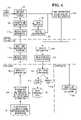
- FIG. 4is a flow chart of an exemplary process that may be implemented in the network access device of the system shown in FIG. 1 .
- System 10includes a personal access network (PAN) device such as a wearable computer 14 , a personal area network receiver 18 , and a server 20 .
- PANpersonal access network
- System 10may also a computer station 24 that may be a checkout terminal or the like.
- Wearable computer 14is comprised of a low power transmitter, low frequency transmitter that is powered by the human body salinity.
- Device 14generates an external electric field that is transmitted by the human body brought in close proximity or contact with PAN receiver 18 .
- Device 14is shown in more detail in FIG. 2 .
- Device 14is powered by an internal power source 30 such as a watch battery or the like.
- Power source 30is coupled to an oscillator 32 to generate an electrical potential between electrode 34 and a virtual ground electrode 38 .
- Virtual ground electrode 38is held at zero potential by an operational amplifier within oscillator 32 so a current flows to ground through the oscillator electrode.
- the electrodesact as point charges that produce dipole fields.
- the body of the person wearing device 14cuts the electric field lines of these dipole fields, and at close proximity to electrodes 34 and 38 , the body of the person acts as a charge reservoir so the current to ground increases.
- a device of this typeis described in an article entitled Applying Elecric Field Sensing to Human - Computer Interfaces by T. Zimmerman, J. Smith, J. Paradiso, D. Aliport, and N. Gershenfeld that is part of the CHI '95 Proceedings Papers. That article is hereby incorporated by reference in its entirety. Such a device generates a signal having a current measured in picoamps and its frequency is less than 1 MHz.
- a data storage unit 40 in which personal identification data and/or financial account data may be storedis also coupled to power source 30 .
- modulator 44retrieves user data from storage unit 40 and modulator 44 modulates the current at electrode 34 .
- the modulated currentis capacitively coupled to the wearer's body and a low power, low frequency signal modulated with the personal identification data is emitted by the wearer.
- the modulated signalmay be received and demodulated to obtain the user data.
- PAN receiver 18may also be provided with a low power, low frequency transmitter that may be used to return data to device 14 .
- receiver 18is provided with a visual and/or audio indicator that a data message for device 14 is ready. To receive the message, the wearer again brings a finger or other body part into proximity or contact with PAN receiver 18 and the signal from the transmitter of receiver 18 is coupled to the person's body.
- the signalmay then be detected at the ground electrode as the modulated signal at electrode 34 ceases upon release of the electrical switch activating modulator 44 .
- the modulations in the ground currentmay be demodulated and used to generate data that may be stored in storage unit 40 .
- datamay be transferred between PAN receiver 18 and device 14 to update financial data such as that that may be stored in a smart card or the like.
- device 14may be used to provide user data such as personal identification data or financial transaction data to a PAN receiver 18 for processing by a retail establishment computer server 20 .
- Server 20may use the personal identification data to query a customer database for information about the identified customer.
- Server 20may use the customer data to retrieve a promotion offer that corresponds to the customer's buying habits and other data stored in the customer database.
- the offer datamay be presented to the customer through the display of a computer station 24 associated with PAN receiver 18 .
- Computer station 18may be an application specific integrated circuit (ASIC) for displaying promotion data or it may be a checkout terminal for processing payment data.
- ASICapplication specific integrated circuit
- the personal identification data received from device 14may include financial account data that may be used by server 20 to generate data messages for obtaining credit card transaction authorization through a payment processor.
- server 20Upon receipt of the authorization code, server 20 sends an authorization message to station 24 so the transaction may be completed. Also, server 20 may send transaction data to PAN receiver 18 for transmission to device 14 if PAN receiver 18 is provided with a transmitter for communicating with device 14 .
- device 14 and receiver 18may communicate in a unidirectional mode or in a bi-directional mode.
- User personal data storage 40may be used to store a personal identification key such a preferred customer identification number or other identification codes such as a key generated from biometric data to further enhance the security of the system.
- Storage unit 40may also include credit card data or other financial account data as may be stored in a smart card or the like.
- a select feature function(block 100 ) may be activated by a user with dedicated actuators on device 14 or through a limited function keyboard of the device.
- the featuresinclude personal identification, payment transaction, or other functions that may be available through server 20 of system 10 .
- Personal identificationmay be used to retrieve promotion offers or other customer incentives while payment transaction may be used to effect payment at a checkout terminal or the like.
- a retrieve user information function(block 104 ) queries storage unit 40 for the data that corresponds to the activated function. This data is provided to a send user information function (block 108 ) for transmission to PAN receiver 18 .
- FIG. 4An exemplary process of the send user function is shown in FIG. 4 . That process receives user information, either personal identification data or financial transaction data, (block 180 ) and modulates the current at electrode 34 with the received data (block 184 ).
- the method of modulationmay be according to any known scheme of low power, low frequency signal modulation.
- the messages containing the user information datamay formatted according to any known message format used for such purposes or it may be a proprietary scheme used to communicate with a server 20 .
- the modulated signalis coupled to electrode 34 (block 188 ) so it may be capacitively coupled to the wearer's body for transmission.
- PAN receiver 18includes a function for receiving the low power, low frequency signal emitted by the wearer's body and demodulating that signal to obtain the user information (block 110 ). This information may then be used to generate data messages for communication with server 20 (block 114 ).
- Server 20includes a function to receive the user data messages (block 118 ) and use the information to validate and authenticate the user (block 120 ).
- PAN receivermay be coupled to a fingerprint imaging device that generates an image of a person's fingerprint and encodes that data for transmission to server 20 .
- the validate and authenticate functionmay then compare the biometric data received from device 14 to the fingerprint image to determine whether the wearer corresponds to the received user information. Other known validation schemes may be used such as entry of a PIN code or the like.
- server 20determines whether a payment transaction is occurring and activates the make payment function (block 124 ) in response.
- the make payment functionuses the user data to generate the necessary data messages for communication with a payment processor.
- the receive confirmation function(block 128 ) provides an authorization message to send data function (block 130 ) for server 20 .
- the data messageis passed to the retrieve user data function (block 134 ) for server 20 .
- the retrieve user data functiondetermines the location and/or function of PAN receiver 18 . For example, location of PAN receiver 18 at a promotion site may result in the retrieve user data function of server 20 querying database 48 to determine an activity level for the customer. This data may be used to generate a promotion offer, discount, or the like. This data may then be formatted in a data message and provided to the send data message function (block 130 ) of server 20 . This function may then send messages to PAN receiver 18 or computer station 24 .
- Data messages for device 14are received by the receiver function (block 138 ) of PAN receiver 18 and converted to the low power, low frequency signal levels and format for device 14 by the send data function (block 140 ).
- This signalis received by the wearer's body and detected at electrode 38 by receive data function (block 144 ) of device 14 .
- the datamay be displayed at wearable device 14 by display data function (block 148 ) and/or stored in storage unit 40 by store data function (block 150 ).
- data messages sent from server 20 to computer station 24are received, processed, and displayed by functions resident in computer station 24 (block 154 ).
- wearable computersare issued to customers with storage units 40 that contain their personal identification data and/or financial account data for credit card, smart card, or other financial token transactions.
- PAN receiversare then installed at promotion sites throughout a retail establishment or the like or in association with checkout or other payment terminals.
- the PAN receiversare programmed to communicate in data messages that comply with the network communication requirements of the network managed by server 20 .
- Server 20is also provided with the functions for validating and authenticating users with data received from wearable computers.
- customers upon the premises of an establishing having PAN receiversmay then access the network managed by server 20 by activating wearable device 14 to generate a personal identification signal or a financial transaction signal.
- PAN receiver 18may then provided the personal identification or financial transaction signal in a network compatible message to server 20 for authentication and validation and other processing.
- Server 20responses with appropriate data messages that may be returned to wearable computer 14 via PAN receiver 18 or to computer station 24 . In this manner, customers are able to access an establishment's computer system at network access points without significant risk of compromising personal identification or financial account data.
Landscapes
- Engineering & Computer Science (AREA)
- Physics & Mathematics (AREA)
- General Physics & Mathematics (AREA)
- Computer Networks & Wireless Communication (AREA)
- Business, Economics & Management (AREA)
- Theoretical Computer Science (AREA)
- Computer Security & Cryptography (AREA)
- General Business, Economics & Management (AREA)
- Strategic Management (AREA)
- Accounting & Taxation (AREA)
- Computer Hardware Design (AREA)
- General Engineering & Computer Science (AREA)
- Microelectronics & Electronic Packaging (AREA)
- Software Systems (AREA)
- Computing Systems (AREA)
- Signal Processing (AREA)
- Cash Registers Or Receiving Machines (AREA)
- Management, Administration, Business Operations System, And Electronic Commerce (AREA)
Abstract
Description
Claims (17)
Priority Applications (2)
| Application Number | Priority Date | Filing Date | Title |
|---|---|---|---|
| US10/112,318US7352996B2 (en) | 2002-03-29 | 2002-03-29 | System and method for coupling users to a retail computer system with low risk of eavesdropping |
| EP03251556AEP1351112A3 (en) | 2002-03-29 | 2003-03-13 | System and method for coupling users to a retail computer system with low risk of eavesdropping |
Applications Claiming Priority (1)
| Application Number | Priority Date | Filing Date | Title |
|---|---|---|---|
| US10/112,318US7352996B2 (en) | 2002-03-29 | 2002-03-29 | System and method for coupling users to a retail computer system with low risk of eavesdropping |
Publications (2)
| Publication Number | Publication Date |
|---|---|
| US20030184430A1 US20030184430A1 (en) | 2003-10-02 |
| US7352996B2true US7352996B2 (en) | 2008-04-01 |
Family
ID=28041016
Family Applications (1)
| Application Number | Title | Priority Date | Filing Date |
|---|---|---|---|
| US10/112,318Expired - LifetimeUS7352996B2 (en) | 2002-03-29 | 2002-03-29 | System and method for coupling users to a retail computer system with low risk of eavesdropping |
Country Status (2)
| Country | Link |
|---|---|
| US (1) | US7352996B2 (en) |
| EP (1) | EP1351112A3 (en) |
Cited By (15)
| Publication number | Priority date | Publication date | Assignee | Title |
|---|---|---|---|---|
| US20070281614A1 (en)* | 2006-06-01 | 2007-12-06 | Motorola, Inc. | Method and apparatus for dual mode communications |
| US20080294722A1 (en)* | 2005-12-08 | 2008-11-27 | Electronics And Telecommunications Research Instit | Method and Apparatus for Providing Touch and Play (Tap) - Based Service and System Using the Method and Apparatus |
| US20090111504A1 (en)* | 2005-04-04 | 2009-04-30 | Research In Motion Limited | Determining a target transmit power of a wireless transmission |
| US20100045446A1 (en)* | 2008-08-22 | 2010-02-25 | Electronics And Telecommunications Research Institute | Rfid system using human body communication |
| US20100185545A1 (en)* | 2009-01-22 | 2010-07-22 | First Data Corporation | Dynamic primary account number (pan) and unique key per card |
| US20100264209A1 (en)* | 2009-04-21 | 2010-10-21 | Paul Tessier | Automatic touch identification system and method thereof |
| US20100321159A1 (en)* | 2009-06-18 | 2010-12-23 | Authentec, Inc. | Touch based data communication using biometric finger sensor and associated methods |
| US20110102137A1 (en)* | 2008-01-09 | 2011-05-05 | Nanoident Technologies Ag | Biometric Security Device |
| US20120317024A1 (en)* | 2011-06-10 | 2012-12-13 | Aliphcom | Wearable device data security |
| US20120317035A1 (en)* | 2009-01-22 | 2012-12-13 | First Data Corporation | Processing transactions with an extended application id and dynamic cryptograms |
| US8668145B2 (en) | 2009-04-21 | 2014-03-11 | Technology Innovators Inc. | Automatic touch identification system and method thereof |
| US8990118B1 (en) | 2009-05-04 | 2015-03-24 | United Services Automobile Association (Usaa) | Laser identification devices and methods |
| US9892249B2 (en) | 2014-09-29 | 2018-02-13 | Xiaomi Inc. | Methods and devices for authorizing operation |
| US10628881B2 (en)* | 2009-01-22 | 2020-04-21 | First Data Corporation | Processing transactions with an extended application ID and dynamic cryptograms |
| US20210019744A1 (en)* | 2019-07-17 | 2021-01-21 | Capital One Services, Llc | Body area network facilitated authentication or payment authorization |
Families Citing this family (14)
| Publication number | Priority date | Publication date | Assignee | Title |
|---|---|---|---|---|
| KR100847053B1 (en)* | 2000-09-30 | 2008-07-17 | 가부시키가이샤 세가 | Service ticket issuing system and service ticket issuing service |
| DE10232934A1 (en)* | 2002-07-19 | 2004-01-29 | Ident Technology Ag | Handle device and safety circuit arrangement, in particular for a power tool |
| CN100571136C (en)* | 2006-04-11 | 2009-12-16 | 华为技术有限公司 | Personal area network and communication method for devices therein |
| KR100948605B1 (en)* | 2008-04-28 | 2010-03-24 | 한국전자통신연구원 | Fingerprint authentication method of human body communication |
| GB2474060A (en)* | 2009-10-05 | 2011-04-06 | Sero Solutions Ltd | An antenna suitable for use with the Near Field Communication standard is fitted to a human finger |
| JP2012039370A (en)* | 2010-08-06 | 2012-02-23 | Sony Corp | Communication system and communication device |
| US20130173372A1 (en)* | 2011-12-28 | 2013-07-04 | Navendu Misra | Electronic Coupon Management |
| US9569625B2 (en)* | 2013-06-11 | 2017-02-14 | Google Inc. | Wearable device multi-mode system |
| KR101869624B1 (en) | 2013-11-22 | 2018-06-21 | 선전 구딕스 테크놀로지 컴퍼니, 리미티드 | Secure human fingerprint sensor |
| WO2015081326A1 (en)* | 2013-11-27 | 2015-06-04 | Shenzhen Huiding Technology Co., Ltd. | Wearable communication devices for secured transaction and communication |
| US10128907B2 (en) | 2014-01-09 | 2018-11-13 | Shenzhen GOODIX Technology Co., Ltd. | Fingerprint sensor module-based device-to-device communication |
| KR20160129874A (en) | 2014-07-07 | 2016-11-09 | 선전 후이딩 테크놀로지 컴퍼니 리미티드 | Integration of touch screen and fingerprint sensor assembly |
| CN104283876A (en)* | 2014-09-29 | 2015-01-14 | 小米科技有限责任公司 | Operation authorization method and device |
| US10685357B2 (en)* | 2016-03-14 | 2020-06-16 | American Express Travel Related Services Company, Inc. | Systems and methods for regulating transactions |
Citations (9)
| Publication number | Priority date | Publication date | Assignee | Title |
|---|---|---|---|---|
| US5682032A (en)* | 1996-02-22 | 1997-10-28 | Philipp; Harald | Capacitively coupled identity verification and escort memory apparatus |
| US5796827A (en)* | 1996-11-14 | 1998-08-18 | International Business Machines Corporation | System and method for near-field human-body coupling for encrypted communication with identification cards |
| US5914701A (en)* | 1995-05-08 | 1999-06-22 | Massachusetts Institute Of Technology | Non-contact system for sensing and signalling by externally induced intra-body currents |
| US6034617A (en)* | 1998-12-04 | 2000-03-07 | Eaton Corporation | Operator intent based passive keyless vehicle control system |
| US6211799B1 (en)* | 1997-11-06 | 2001-04-03 | Massachusetts Institute Of Technology | Method and apparatus for transbody transmission of power and information |
| US6642837B1 (en)* | 1999-10-19 | 2003-11-04 | Massachusetts Institute Of Technology | Method and apparatus for touch-activated identification and information transfer |
| US6711161B1 (en)* | 2000-02-24 | 2004-03-23 | Advanced Micro Devices, Inc. | Arrangement for providing linearly scaleable address forwarding tables within multiple network switch modules |
| US6771161B1 (en)* | 2000-06-27 | 2004-08-03 | Matsushita Electric Works, Ltd. | Data transmission system using a human body as a signal transmission path |
| US6938821B2 (en)* | 2000-09-18 | 2005-09-06 | E-Micro Corporation | Method and apparatus for associating identification and personal data for multiple magnetic stripe cards or other sources |
Family Cites Families (6)
| Publication number | Priority date | Publication date | Assignee | Title |
|---|---|---|---|---|
| US5555376A (en)* | 1993-12-03 | 1996-09-10 | Xerox Corporation | Method for granting a user request having locational and contextual attributes consistent with user policies for devices having locational attributes consistent with the user request |
| AU6339698A (en)* | 1997-02-27 | 1998-09-18 | Inframedia Corporation | In-store consumer targeted messaging system |
| US6104913A (en)* | 1998-03-11 | 2000-08-15 | Bell Atlantic Network Services, Inc. | Personal area network for personal telephone services |
| EP1024626A1 (en)* | 1999-01-27 | 2000-08-02 | International Business Machines Corporation | Method, apparatus, and communication system for exchange of information in pervasive environments |
| JP2001195368A (en)* | 1999-11-01 | 2001-07-19 | Sony Corp | Authentication information communication system, authentication information communication method, portable information processor and program provision medium |
| FR2813470A1 (en)* | 2000-08-24 | 2002-03-01 | Xavier Renard | Advertising digital word information broadcasting having server sending terminal receiver information following previously established user profile/targeting user. |
- 2002
- 2002-03-29USUS10/112,318patent/US7352996B2/ennot_activeExpired - Lifetime
- 2003
- 2003-03-13EPEP03251556Apatent/EP1351112A3/ennot_activeWithdrawn
Patent Citations (9)
| Publication number | Priority date | Publication date | Assignee | Title |
|---|---|---|---|---|
| US5914701A (en)* | 1995-05-08 | 1999-06-22 | Massachusetts Institute Of Technology | Non-contact system for sensing and signalling by externally induced intra-body currents |
| US5682032A (en)* | 1996-02-22 | 1997-10-28 | Philipp; Harald | Capacitively coupled identity verification and escort memory apparatus |
| US5796827A (en)* | 1996-11-14 | 1998-08-18 | International Business Machines Corporation | System and method for near-field human-body coupling for encrypted communication with identification cards |
| US6211799B1 (en)* | 1997-11-06 | 2001-04-03 | Massachusetts Institute Of Technology | Method and apparatus for transbody transmission of power and information |
| US6034617A (en)* | 1998-12-04 | 2000-03-07 | Eaton Corporation | Operator intent based passive keyless vehicle control system |
| US6642837B1 (en)* | 1999-10-19 | 2003-11-04 | Massachusetts Institute Of Technology | Method and apparatus for touch-activated identification and information transfer |
| US6711161B1 (en)* | 2000-02-24 | 2004-03-23 | Advanced Micro Devices, Inc. | Arrangement for providing linearly scaleable address forwarding tables within multiple network switch modules |
| US6771161B1 (en)* | 2000-06-27 | 2004-08-03 | Matsushita Electric Works, Ltd. | Data transmission system using a human body as a signal transmission path |
| US6938821B2 (en)* | 2000-09-18 | 2005-09-06 | E-Micro Corporation | Method and apparatus for associating identification and personal data for multiple magnetic stripe cards or other sources |
Non-Patent Citations (1)
| Title |
|---|
| Zimmerman, T.G., Smith, R.J., Paradiso, J.A., Allport, D. and Gershenfeld, N. "Applying Electric Field Sensing to Human-Computer Interfaces."CHI '95 Proceedings Papers. 1995, Online. Internet. Available: <http://www.acm.org/sigchi/chi95/Electronic/documnts/papers/tgz<SUB>-</SUB>bdy.htm>. |
Cited By (27)
| Publication number | Priority date | Publication date | Assignee | Title |
|---|---|---|---|---|
| US20090111504A1 (en)* | 2005-04-04 | 2009-04-30 | Research In Motion Limited | Determining a target transmit power of a wireless transmission |
| US9503992B2 (en)* | 2005-04-04 | 2016-11-22 | Blackberry Limited | Determining a target transmit power of a wireless transmission |
| US8165522B2 (en)* | 2005-12-08 | 2012-04-24 | Electronics And Telecommunications Research Institute | Method and apparatus for providing touch and play (TAP)—based service and system using the method and apparatus |
| US20080294722A1 (en)* | 2005-12-08 | 2008-11-27 | Electronics And Telecommunications Research Instit | Method and Apparatus for Providing Touch and Play (Tap) - Based Service and System Using the Method and Apparatus |
| US20070281614A1 (en)* | 2006-06-01 | 2007-12-06 | Motorola, Inc. | Method and apparatus for dual mode communications |
| US8847732B2 (en)* | 2008-01-09 | 2014-09-30 | Nanoident Technologies Ag | Biometric security device |
| US20110102137A1 (en)* | 2008-01-09 | 2011-05-05 | Nanoident Technologies Ag | Biometric Security Device |
| US20100045446A1 (en)* | 2008-08-22 | 2010-02-25 | Electronics And Telecommunications Research Institute | Rfid system using human body communication |
| US10354321B2 (en)* | 2009-01-22 | 2019-07-16 | First Data Corporation | Processing transactions with an extended application ID and dynamic cryptograms |
| US10037524B2 (en) | 2009-01-22 | 2018-07-31 | First Data Corporation | Dynamic primary account number (PAN) and unique key per card |
| US10628881B2 (en)* | 2009-01-22 | 2020-04-21 | First Data Corporation | Processing transactions with an extended application ID and dynamic cryptograms |
| US20120317035A1 (en)* | 2009-01-22 | 2012-12-13 | First Data Corporation | Processing transactions with an extended application id and dynamic cryptograms |
| US20100185545A1 (en)* | 2009-01-22 | 2010-07-22 | First Data Corporation | Dynamic primary account number (pan) and unique key per card |
| US8668145B2 (en) | 2009-04-21 | 2014-03-11 | Technology Innovators Inc. | Automatic touch identification system and method thereof |
| US8297499B2 (en) | 2009-04-21 | 2012-10-30 | Technology Innovators Inc. | Automatic touch identification system and method thereof |
| US20100264209A1 (en)* | 2009-04-21 | 2010-10-21 | Paul Tessier | Automatic touch identification system and method thereof |
| US9792465B2 (en) | 2009-04-21 | 2017-10-17 | Koninklijke Philips N.V. | Automatic touch identification system and method thereof |
| US11176555B1 (en) | 2009-05-04 | 2021-11-16 | United Services Automobile Association (Usaa) | Laser identification devices and methods |
| US10496991B1 (en) | 2009-05-04 | 2019-12-03 | United Services Automobile Association (Usaa) | Laser identification devices and methods |
| US8990118B1 (en) | 2009-05-04 | 2015-03-24 | United Services Automobile Association (Usaa) | Laser identification devices and methods |
| US20100321159A1 (en)* | 2009-06-18 | 2010-12-23 | Authentec, Inc. | Touch based data communication using biometric finger sensor and associated methods |
| US20120317024A1 (en)* | 2011-06-10 | 2012-12-13 | Aliphcom | Wearable device data security |
| US9892249B2 (en) | 2014-09-29 | 2018-02-13 | Xiaomi Inc. | Methods and devices for authorizing operation |
| US20210019744A1 (en)* | 2019-07-17 | 2021-01-21 | Capital One Services, Llc | Body area network facilitated authentication or payment authorization |
| US11699151B2 (en)* | 2019-07-17 | 2023-07-11 | Capital One Services, Llc | Body area network facilitated authentication or payment authorization |
| US20240005311A1 (en)* | 2019-07-17 | 2024-01-04 | Capital One Services, Llc | Body area network facilitated authentication or payment authorization |
| US12106293B2 (en)* | 2019-07-17 | 2024-10-01 | Capital One Services, Llc | Body area network facilitated authentication or payment authorization |
Also Published As
| Publication number | Publication date |
|---|---|
| EP1351112A2 (en) | 2003-10-08 |
| US20030184430A1 (en) | 2003-10-02 |
| EP1351112A3 (en) | 2007-11-14 |
Similar Documents
| Publication | Publication Date | Title |
|---|---|---|
| US7352996B2 (en) | System and method for coupling users to a retail computer system with low risk of eavesdropping | |
| US8407097B2 (en) | Proximity transaction apparatus and methods of use thereof | |
| KR101100286B1 (en) | Methods and systems for creating and operating biometrically enabled multipurpose credential management devices | |
| US6424845B1 (en) | Portable communication device | |
| CA2732869C (en) | Methods, systems and computer readable media for storing and redeeming electronic certificates using a wireless smart card | |
| US20080222047A1 (en) | Device and Method for Conducting Secure Economic Transactions with a Programmable Magnetic Stripe | |
| US8468071B2 (en) | Processing transactions using a register portion to track transactions | |
| US20030075610A1 (en) | Electronic credit card-ecc | |
| US7652573B2 (en) | Object presence analysis system and method | |
| JP2005507127A (en) | Security access system | |
| US20160189127A1 (en) | Systems And Methods For Creating Dynamic Programmable Credential and Security Cards | |
| WO2012064882A1 (en) | Apparatus and method for storing electronic receipts on a unified card or smartphone | |
| US20120323710A1 (en) | Method and system for storing and using identifying account information on an electronic device | |
| US20250095021A1 (en) | System and method for processing digital coupons | |
| US20080217396A1 (en) | Device and method for conducting secure economic transactions | |
| US9619800B1 (en) | Systems and methods for processing transactions | |
| US20100257254A1 (en) | Apparatus, Method and System for Securely Handling Digital Transaction Documents | |
| KR20200132075A (en) | Recording Medium Storage Program for Executing Application for Articles Management Using Information of NFC Chip Entrained to Articles | |
| KR100837121B1 (en) | Electronic coupon service system and method using smart card | |
| KR100809941B1 (en) | Information processing method and system, information processing device and program recording medium | |
| US20090327086A1 (en) | Non-Optical Mobile Electronic Transaction System, Device and Method Therefor | |
| JP2003050960A (en) | Security system for electronic money | |
| KR101148300B1 (en) | System and method for electronic coupon service using smart card | |
| KR20090099840A (en) | Electronic Voucher Service System and Method Using Smart Card | |
| AU2004250655B2 (en) | Method and system for creating and operating biometrically enabled multi-purpose credential management devices |
Legal Events
| Date | Code | Title | Description |
|---|---|---|---|
| AS | Assignment | Owner name:NCR CORPORATION, OHIO Free format text:ASSIGNMENT OF ASSIGNORS INTEREST;ASSIGNOR:KUMAR, ALOK;REEL/FRAME:012752/0371 Effective date:20020326 | |
| STCF | Information on status: patent grant | Free format text:PATENTED CASE | |
| FPAY | Fee payment | Year of fee payment:4 | |
| AS | Assignment | Owner name:JPMORGAN CHASE BANK, N.A., AS ADMINISTRATIVE AGENT, ILLINOIS Free format text:SECURITY AGREEMENT;ASSIGNORS:NCR CORPORATION;NCR INTERNATIONAL, INC.;REEL/FRAME:032034/0010 Effective date:20140106 Owner name:JPMORGAN CHASE BANK, N.A., AS ADMINISTRATIVE AGENT Free format text:SECURITY AGREEMENT;ASSIGNORS:NCR CORPORATION;NCR INTERNATIONAL, INC.;REEL/FRAME:032034/0010 Effective date:20140106 | |
| FPAY | Fee payment | Year of fee payment:8 | |
| AS | Assignment | Owner name:JPMORGAN CHASE BANK, N.A., ILLINOIS Free format text:SECURITY AGREEMENT;ASSIGNORS:NCR CORPORATION;NCR INTERNATIONAL, INC.;REEL/FRAME:038646/0001 Effective date:20160331 | |
| MAFP | Maintenance fee payment | Free format text:PAYMENT OF MAINTENANCE FEE, 12TH YEAR, LARGE ENTITY (ORIGINAL EVENT CODE: M1553); ENTITY STATUS OF PATENT OWNER: LARGE ENTITY Year of fee payment:12 | |
| AS | Assignment | Owner name:NCR VOYIX CORPORATION, GEORGIA Free format text:RELEASE OF PATENT SECURITY INTEREST;ASSIGNOR:JPMORGAN CHASE BANK, N.A., AS ADMINISTRATIVE AGENT;REEL/FRAME:065346/0531 Effective date:20231016 Owner name:BANK OF AMERICA, N.A., AS ADMINISTRATIVE AGENT, NORTH CAROLINA Free format text:SECURITY INTEREST;ASSIGNOR:NCR VOYIX CORPORATION;REEL/FRAME:065346/0168 Effective date:20231016 | |
| AS | Assignment | Owner name:NCR VOYIX CORPORATION, GEORGIA Free format text:CHANGE OF NAME;ASSIGNOR:NCR CORPORATION;REEL/FRAME:065820/0704 Effective date:20231013 |