US7352545B2 - Compressor terminal fault interruption method and apparatus - Google Patents
Compressor terminal fault interruption method and apparatusDownload PDFInfo
- Publication number
- US7352545B2 US7352545B2US10/794,117US79411704AUS7352545B2US 7352545 B2US7352545 B2US 7352545B2US 79411704 AUS79411704 AUS 79411704AUS 7352545 B2US7352545 B2US 7352545B2
- Authority
- US
- United States
- Prior art keywords
- circuit
- current
- terminal
- compressor
- reference signal
- Prior art date
- Legal status (The legal status is an assumption and is not a legal conclusion. Google has not performed a legal analysis and makes no representation as to the accuracy of the status listed.)
- Expired - Lifetime, expires
Links
- 238000000034methodMethods0.000titleabstractdescription11
- 238000013022ventingMethods0.000claimsabstractdescription17
- 239000011521glassSubstances0.000claimsdescription47
- 238000010438heat treatmentMethods0.000claimsdescription3
- 239000003990capacitorSubstances0.000description5
- 239000011810insulating materialSubstances0.000description5
- 238000005057refrigerationMethods0.000description4
- 238000001514detection methodMethods0.000description3
- 239000003507refrigerantSubstances0.000description3
- 230000004913activationEffects0.000description2
- 230000015556catabolic processEffects0.000description2
- 238000010586diagramMethods0.000description2
- 238000002955isolationMethods0.000description2
- 230000002035prolonged effectEffects0.000description2
- 238000000926separation methodMethods0.000description2
- 230000001960triggered effectEffects0.000description2
- 230000005355Hall effectEffects0.000description1
- 230000006978adaptationEffects0.000description1
- 238000004378air conditioningMethods0.000description1
- 238000010276constructionMethods0.000description1
- 230000001066destructive effectEffects0.000description1
- 230000000694effectsEffects0.000description1
- 238000001914filtrationMethods0.000description1
- 230000000977initiatory effectEffects0.000description1
- 238000013178mathematical modelMethods0.000description1
- 238000005259measurementMethods0.000description1
- 239000002184metalSubstances0.000description1
- 230000007935neutral effectEffects0.000description1
- 238000004088simulationMethods0.000description1
- 239000007787solidSubstances0.000description1
- 230000002459sustained effectEffects0.000description1
- 230000000007visual effectEffects0.000description1
Images


Classifications
- H—ELECTRICITY
- H02—GENERATION; CONVERSION OR DISTRIBUTION OF ELECTRIC POWER
- H02H—EMERGENCY PROTECTIVE CIRCUIT ARRANGEMENTS
- H02H7/00—Emergency protective circuit arrangements specially adapted for specific types of electric machines or apparatus or for sectionalised protection of cable or line systems, and effecting automatic switching in the event of an undesired change from normal working conditions
- H02H7/08—Emergency protective circuit arrangements specially adapted for specific types of electric machines or apparatus or for sectionalised protection of cable or line systems, and effecting automatic switching in the event of an undesired change from normal working conditions for dynamo-electric motors
- F—MECHANICAL ENGINEERING; LIGHTING; HEATING; WEAPONS; BLASTING
- F04—POSITIVE - DISPLACEMENT MACHINES FOR LIQUIDS; PUMPS FOR LIQUIDS OR ELASTIC FLUIDS
- F04B—POSITIVE-DISPLACEMENT MACHINES FOR LIQUIDS; PUMPS
- F04B49/00—Control, e.g. of pump delivery, or pump pressure of, or safety measures for, machines, pumps, or pumping installations, not otherwise provided for, or of interest apart from, groups F04B1/00 - F04B47/00
- F04B49/06—Control using electricity
- F04B49/065—Control using electricity and making use of computers
- H—ELECTRICITY
- H02—GENERATION; CONVERSION OR DISTRIBUTION OF ELECTRIC POWER
- H02H—EMERGENCY PROTECTIVE CIRCUIT ARRANGEMENTS
- H02H3/00—Emergency protective circuit arrangements for automatic disconnection directly responsive to an undesired change from normal electric working condition with or without subsequent reconnection ; integrated protection
- H02H3/08—Emergency protective circuit arrangements for automatic disconnection directly responsive to an undesired change from normal electric working condition with or without subsequent reconnection ; integrated protection responsive to excess current
- F—MECHANICAL ENGINEERING; LIGHTING; HEATING; WEAPONS; BLASTING
- F04—POSITIVE - DISPLACEMENT MACHINES FOR LIQUIDS; PUMPS FOR LIQUIDS OR ELASTIC FLUIDS
- F04B—POSITIVE-DISPLACEMENT MACHINES FOR LIQUIDS; PUMPS
- F04B2203/00—Motor parameters
- F04B2203/02—Motor parameters of rotating electric motors
- F04B2203/0201—Current
- F—MECHANICAL ENGINEERING; LIGHTING; HEATING; WEAPONS; BLASTING
- F04—POSITIVE - DISPLACEMENT MACHINES FOR LIQUIDS; PUMPS FOR LIQUIDS OR ELASTIC FLUIDS
- F04B—POSITIVE-DISPLACEMENT MACHINES FOR LIQUIDS; PUMPS
- F04B2203/00—Motor parameters
- F04B2203/02—Motor parameters of rotating electric motors
- F04B2203/0205—Temperature
- F—MECHANICAL ENGINEERING; LIGHTING; HEATING; WEAPONS; BLASTING
- F04—POSITIVE - DISPLACEMENT MACHINES FOR LIQUIDS; PUMPS FOR LIQUIDS OR ELASTIC FLUIDS
- F04B—POSITIVE-DISPLACEMENT MACHINES FOR LIQUIDS; PUMPS
- F04B2203/00—Motor parameters
- F04B2203/02—Motor parameters of rotating electric motors
- F04B2203/0212—Amplitude of the electric current
Definitions
- the present inventionrelates generally to an over-current protection method and circuit, and more particularly to a method and circuit for disconnecting power to a motor for a hermetic compressor upon detecting excess current.
- Refrigeration systemssuch as residential refrigerators, use electric motor powered hermetic compressors which compress the system refrigerant according to principles well known in the art.
- the compressor motor in a systemcan enter a fault mode wherein the power lines to the compressor input terminals carry excessively high current. This high current condition may result in a phenomenon commonly referred to as “terminal venting”.
- Terminal ventingis generally characterized by a separation of the metallic compressor input terminal pins from the surrounding insulating material in which the pins are mounted. This can occur if excessively high current is supplied to the terminals for sufficient time to destroy the glass insulating seal. The problem is exacerbated by the different thermal expansion coefficients of the pins and the insulating material thereby causing destructive tensile stresses in the glass. The end result of such a failure is damage to the hermetic seal of the compressor terminal and, in some situations, the uncontrolled release of refrigerant gas.
- compressor manufacturersincorporate mechanical safeguards into their compressor designs to reduce the likelihood and/or the effects of terminal venting.
- Some conventional compressorsemploy robust insulating materials with high temperature breakdown characteristics.
- Other compressorsinclude covers which enclose the compressor terminals.
- the current flowing through the terminalis detected. If the detected current exceeds a threshold level that, unless substantially. immediately terminated, will cause the pin/glass temperature differential to rapidly exceed a threshold level resulting in glass stresses that will cause the pin-to-glass failure and terminal venting, power through the terminal is immediately terminated.
- the threshold current levelis much higher than locked rotor current for the compressor motor, preferably at least two times the locked rotor current.
- the threshold current selected for a particular terminalmust be lower than that which correlates to simultaneous pin and glass temperatures at the failure level.
- the present inventioncan be implemented by an exemplary protection circuit connected in series between the power lines and terminal of the compressor which detects the presence of a motor fault or other over-current condition and disconnects power to the terminal to prevent terminal venting due to this condition.
- the circuitgenerally includes a line-connected power supply for powering the circuit, a current sensor for sensing the current drawn by the compressor motor and a control circuit for disconnecting power to the motor when a fault is detected.
- the circuitmay include an audible or visual alarm to indicate the presence of a fault.
- the method and circuit of the present inventionprotect the compressor terminals, as opposed to the motor coils, by quickly disconnecting power to the compressor, but only upon detection of exceptionally high current levels.
- This high thresholdpermits simultaneous operation of conventional interrupt circuits and prevents “nuisance triggering” as a result of the large current demands at motor start-up or current noise spikes that may occur during operation.
- the current threshold of the present protection circuitis quite high relative to the locked rotor current, damage to the compressor terminals is nonetheless prevented because the response time of the circuit is substantially faster than conventional interrupt circuits. For example, current is terminated within 20 milliseconds of detecting the preset current threshold.
- the exceptionally high currentis removed from the compressor terminals before the temperature of the terminal pin causes damage to the pin-to-glass seal.
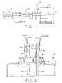
- FIG. 1is a block diagram of a portion of a refrigeration system with an over-current protection circuit according to the present invention.
- FIG. 2is a cross-sectional view of a compressor showing the compressor input terminals.
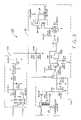
- FIG. 3is a schematic diagram of an over-current protection circuit according to an exemplary embodiment of the present invention.
- FIG. 4is a graphical representation of the temperatures of the pin and glass when high current is applied across the pin.
- FIG. 5is a graphical representation of the differential temperature of the pin and glass of the hermetic terminal for different currents.
- FIG. 6is a further graphical representation of the differential temperature of the pin and glass of the hermetic terminal when different currents are applied.
- FIG. 7is a graphical representation of the maximum principal tensile stress in the hermetic terminal when different currents are applied for seven seconds.
- a power source 12such as a wall outlet
- a compressor motor 14which drives a compressor 16 .
- the present inventionmay be applied to any hermetic compressor used, for example, in air conditioning and refrigeration applications such as the numerous models of compressors commercially available from the assignee of the present application, Tecumseh Products Company.
- compressor 16could be of the type disclosed in U.S. Pat. No. 5,199,898 which is assigned to the assignee of the present invention and is expressly incorporated herein by reference.
- a protection circuit 100is connected between power source 12 and terminal assembly 18 for the compressor 16 and motor 14 to detect an excessive current draw and disconnect power in response thereto.
- protection circuit 100will be described as disconnecting the common line to compressor motor 14 upon detecting an over-current condition, protection circuit 100 could readily be adapted to disconnect either the high signal or the common signal provided to motor 14 .
- Compressor 16generally includes a hermetic housing 17 and a terminal assembly 18 in which are mounted three terminals (only two shown).
- Terminal 20carries the power high line from power source 12 to compressor motor 14 through wire 22 , connector 24 , and pin 26 .
- terminal 28carries the common line from power source 12 through wire 30 , connector 32 , and pin 34 .
- Terminal pins 26 and 34are mounted within housing 18 and glass insulating material 36 according to principles well known in the art.
- a terminal venting conditionis characterized by separation between any of terminal pins 26 , 34 , or the neutral terminal pin (not shown) from glass insulating material 36 , potentially resulting in an uncontrolled release of refrigerant from compressor 16 .
- the excessive current drawn which may lead to such a failureis prevented from reaching compressor 16 by over-protection current 100 as described below.
- FIG. 3shows a protection circuit 100 which can be used to implement the method and apparatus of the present invention.
- Circuit 100includes a regulator circuit 102 to establish a fixed DC voltage for comparing to a voltage representing the current drawn by compressor motor 14 , a current sensing circuit 104 for deriving this representative voltage, and a control circuit 106 for disconnecting power to compressor 16 as will be further described below.
- Regulator circuit 102includes a transformer T 1 , shown as a 36 volt device, the primary side of which is connected to 117 VAC power from power source 12 ( FIG. 1 ). The output signal from the secondary side of transformer T 1 is rectified by diodes D 1 , D 2 to produce a 24 VDC signal.
- This 24 VDC signalis used to energize relay RYI as will be further described below.
- the 24 VDC signalis filtered by capacitor C 1 and passed through a 5 volt regulator U 1 to produce a 5 VDC signal at the output of regulator circuit 102 .
- This signalis further filtered by capacitor C 2 , and passed through a voltage divider network in control circuit 106 including resistors R 2 , R 3 .
- the output node 108 of voltage divider R 2 , R 3is the reference voltage used to set a maximum threshold for the acceptable current provided through terminal 18 to compressor motor 14 .
- this threshold reference voltageis set such that the increased current draw associated with motor start-up or other typical operating conditions does not result in activation of circuit 100 .
- the reference voltageis set such that triggering of circuit 100 occurs only upon detection of motor 14 current substantially higher than locked rotor current.
- the threshold current level causing activation of the disconnect circuitis that current which, unless substantially immediately terminated, will cause the pin/glass temperature differential to rapidly exceed a threshold level resulting in glass stresses that will cause pin-to-glass failure and terminal venting.
- This threshold currentis much higher than locked rotor current for the compressor motor, for example, at least two times the locked rotor current.
- the threshold current at 115 voltsis 52 amps.
- the threshold current selected for a particular terminalmust be lower than that which correlates to simultaneous pin and glass temperatures at the failure level.
- the 117 VAC high lineis passed through current sensor CS 1 of current sensing circuit 104 to compressor motor 14 (compressor terminal 20 ).
- Current sensor CS 1is a conventional torroidal current sensor, and is connected to resistor R 4 and rectifier D 3 , D 4 . Since small voltage changes are produced by current sensor CS 1 in response to current changes on the 117 VAC power line, Schottky diodes are used for rectifier D 3 , D 4 to minimize the forward voltage drop incurred by the output voltage of current sensor CS 1 . As current through current sensor CS 1 increases, the voltage at the output of rectifier D 3 , D 4 also increases. This signal is passed through resistor R 5 and filtered by resistor R 6 and capacitor C 3 .
- the filtered signalis connected to the positive input of comparator U 2 A of control circuit 106 .
- a diode D 5is connected between the positive input of comparator U 2 A and ground to protect comparator U 2 A in the event a large voltage is generated by current sensor CS 1 . Specifically, if the voltage at the positive input of comparator U 2 A exceeds the 6.2 voltage breakdown voltage of diode D 5 , diode D 5 will reverse bias and conduct to ground, thereby protecting the remainder of circuit 100 .
- the negative input to comparator U 2 Ais connected to the reference voltage at node 108 of voltage divider R 2 , R 3 .
- the output of comparator U 2 Ais connected to pull up resistor R 7 which is connected to the 5 VDC output power from regulator circuit 102 .
- the output of comparator U 2 Ais also connected to Schottky diode D 6 which isolates comparator U 2 A from an AND gate U 3 .
- Both inputs of AND gate U 3are connected together and connected to the filter including resistor R 8 and capacitor C 4 .
- a hysteresis resistor R 9is connected from the output of AND gate U 3 to the inputs.
- comparator U 2 Bfunctions as an inverter.
- the output of comparator U 2 Bis pulled up by resistor R 10 and connected to the gate of transistor Q 1 .
- the drain of transistor Q 1is connected to ground and the source is connected to the low side of the solenoid coil of relay RY 1 .
- the high side of the solenoid coilis connected to the 24 VDC signal from rectifier D 1 , D 2 of regulator circuit 102 .
- Relay RY 1is shown in its energized configuration wherein the common line from power source 12 ( FIG. 1 ) is passed through the switch of RY 1 , terminal 28 of compressor 16 , to compressor motor 14 .
- current sensor CS 1In operation, when excess current is drawn by motor 14 through the 117 VAC high line, current sensor CS 1 produces an output voltage which is rectified by diodes D 3 , D 4 and provided to the positive input of comparator U 2 A after filtering by resistor R 6 and capacitor C 3 . If the voltage exceeds the reference voltage (from note 108 of voltage divider R 2 , R 3 ) at the negative input to comparator U 2 A, comparator U 2 A outputs a positive logic signal. Accordingly, a positive logic signal is present at both inputs to AND gate U 3 , causing a positive output.
- the combination of Schottky diode D 6 and hysteresis resistor R 9latch the output of AND gate U 3 in the logic high state.
- a logic high stateis therefore present at the negative input to comparator U 2 B.
- Control circuit 106is designed such that this signal exceeds the reference voltage at the positive input to comparator U 2 B. Accordingly, comparator U 2 B outputs a logic low signal disabling transistor Q 1 . The path to ground for the solenoid coil of relay RY 1 is thereby removed, de-energizing relay RY 1 such that relay RY 1 switches to an open position.
- relay RY 1When relay RY 1 opens, power is disconnected to compressor motor 14 , and the current passing through current sensor CS 1 quickly goes to zero. This rapid disconnect prevents the excessive current at terminals 20 , 28 (and the third terminal, not shown) from heating terminals 20 . 28 to a temperature resulting in terminal venting.
- circuit 100disables relay RY 1 and maintains relay RY 1 in a disabled state, thereby disconnecting power from compressor motor 14 , until power is removed from circuit 100 and re-applied.
- circuit 1000disables compressor motor 14 , compressor motor 14 remains disabled until it is properly serviced.
- FIG. 4there is provided a graphical representation of the pin and glass temperatures as a function of time when different currents are applied to terminal pin 26 or 34 .
- the higher the pin currentthe more rapid the rise in pin temperature and concomitantly the temperature differential between the pin and glass.
- FIG. 5illustrates this rise in pin/glass temperature differential, and particularly for high current levels, such as 120 amps, the temperature differential curve rises very sharply after only one second following initiation of the high current condition.
- FIG. 6is a similar representation but includes additional current levels in a mathematical simulation.
- FIG. 7shows graphically the rapid rise in maximum principal stresses in the glass as the temperature differential between the glass and pin increases. As is quite evident, the curve is substantially exponential thereby indicating that unless current is terminated at a very early time when the threshold current is detected, rapid heating and failure of the pin-to-glass seal will occur.
- Ta 1 i b 1 t 4 +a 2 i b 2 t 3 +a 3 i b 3 t 2
- Tis the differential temperature between the pin and the glass in degrees Celsius
- icurrent through the pin in amperes
- tthe amount of time in seconds current has been applied.
- the experimental data to generate and validate the curves discussed abovewas obtained by applying different levels of current through the terminal and measuring the temperature of the glass and pin.
- the constants a 1 , a 2 , a 3 , b 1 , b 2 , b 3are derived from the curves and are used for the particular terminal construction tested.
- the constantsare as follows:
- Maximum allowable glass stress and therefore maximum allowable pin-to-glass temperature differentialis determined by measuring the electrical isolation resistance of the pin-to-glass interface, which will be indicative of the glass stress. For example, if the maximum allowable stress for the particular terminal tested was chosen to be 12,500 psi, this correlates to a pin/glass differential temperature of about 210° C. ( FIG. 7 ). As can be seen in FIG. 5 , this temperature differential would be reached under 80 amp current conditions. Since a pin-to-glass temperature differential of 55° C. results from twice the locked rotor current of 40 amps. 52 amps was selected as the threshold current level for power interruption.
- relay RY 1is shown in the exemplary system as the device for disconnecting power between the power source and the compressor motor 14 , this could be replaced by an normally open relay held closed by the circuit, a latching relay, piezoelectric relay, bi-metal relay or solid state relay-type device, such as an SCR, triac, FET, etc. It may also be desirable to have the protection circuit 100 be non-resettable.
- Other potential implementations of the current sensor CS 1can be a transformer isolated hall effect device, GMR, etc., or other current sensing means well known in the art.
- circuit 100could readily be reconfigured to monitor the power demand of compressor motor 14 in terms of watts versus time by way of the technique disclosed in pending U.S. application Ser. No. 09/697,631 filed Oct. 26, 2000, which application is expressly incorporated herein by reference.
- This applicationis therefore intended to cover any variation, uses, or adaptations of the invention using its general principles. Further, this application is intended to cover such departures from the present disclosure as come within known or customary practice in the art to which this invention pertains.
Landscapes
- Engineering & Computer Science (AREA)
- Computer Hardware Design (AREA)
- Mechanical Engineering (AREA)
- General Engineering & Computer Science (AREA)
- Control Of Positive-Displacement Pumps (AREA)
- Control Of Electric Motors In General (AREA)
- Protection Of Generators And Motors (AREA)
Abstract
Description
T=a1ib
In this equation, T is the differential temperature between the pin and the glass in degrees Celsius, i is current through the pin in amperes and t is the amount of time in seconds current has been applied. Once the maximum temperature differential between the pin and glass is determined for a particular terminal, the equation can be solved for current in order to set the threshold level in
| a1= | 1.079 × 10⁻⁴ | ||
| a2= | 2.420 × 10⁻³ | ||
| a3= | 1.4447 × 10⁻² | ||
| b1= | 1.8875 | ||
| b2= | 1.8000 | ||
| b3= | 1.7335 | ||
Maximum allowable glass stress and therefore maximum allowable pin-to-glass temperature differential is determined by measuring the electrical isolation resistance of the pin-to-glass interface, which will be indicative of the glass stress. For example, if the maximum allowable stress for the particular terminal tested was chosen to be 12,500 psi, this correlates to a pin/glass differential temperature of about 210° C. (
Claims (5)
Priority Applications (1)
| Application Number | Priority Date | Filing Date | Title |
|---|---|---|---|
| US10/794,117US7352545B2 (en) | 2000-12-12 | 2004-03-05 | Compressor terminal fault interruption method and apparatus |
Applications Claiming Priority (3)
| Application Number | Priority Date | Filing Date | Title |
|---|---|---|---|
| US25494500P | 2000-12-12 | 2000-12-12 | |
| US10/014,692US6760207B2 (en) | 2000-12-12 | 2001-12-11 | Compressor terminal fault interruption method and apparatus |
| US10/794,117US7352545B2 (en) | 2000-12-12 | 2004-03-05 | Compressor terminal fault interruption method and apparatus |
Related Parent Applications (1)
| Application Number | Title | Priority Date | Filing Date |
|---|---|---|---|
| US10/014,692DivisionUS6760207B2 (en) | 2000-12-12 | 2001-12-11 | Compressor terminal fault interruption method and apparatus |
Publications (2)
| Publication Number | Publication Date |
|---|---|
| US20040174650A1 US20040174650A1 (en) | 2004-09-09 |
| US7352545B2true US7352545B2 (en) | 2008-04-01 |
Family
ID=22966193
Family Applications (2)
| Application Number | Title | Priority Date | Filing Date |
|---|---|---|---|
| US10/014,692Expired - LifetimeUS6760207B2 (en) | 2000-12-12 | 2001-12-11 | Compressor terminal fault interruption method and apparatus |
| US10/794,117Expired - LifetimeUS7352545B2 (en) | 2000-12-12 | 2004-03-05 | Compressor terminal fault interruption method and apparatus |
Family Applications Before (1)
| Application Number | Title | Priority Date | Filing Date |
|---|---|---|---|
| US10/014,692Expired - LifetimeUS6760207B2 (en) | 2000-12-12 | 2001-12-11 | Compressor terminal fault interruption method and apparatus |
Country Status (5)
| Country | Link |
|---|---|
| US (2) | US6760207B2 (en) |
| EP (1) | EP1342304B1 (en) |
| AU (1) | AU2002230756A1 (en) |
| CA (1) | CA2431111C (en) |
| WO (1) | WO2002049178A2 (en) |
Cited By (20)
| Publication number | Priority date | Publication date | Assignee | Title |
|---|---|---|---|---|
| US20090225479A1 (en)* | 2008-02-20 | 2009-09-10 | Nagaraj Jayanth | Compressor Protection and Grid Fault Detection Device |
| US20100111709A1 (en)* | 2003-12-30 | 2010-05-06 | Emerson Climate Technologies, Inc. | Compressor protection and diagnostic system |
| US20100214709A1 (en)* | 2009-02-20 | 2010-08-26 | Won-Door Corporation | Methods and systems relating to overcurrent circuit protection |
| US20110179821A1 (en)* | 2004-12-22 | 2011-07-28 | York International Corporation | Medium voltage starter for a chiller unit |
| US20130000330A1 (en)* | 2010-12-28 | 2013-01-03 | Sanyo Electric Co., Ltd. | Control apparatus and refrigerating apparatus |
| US8964338B2 (en) | 2012-01-11 | 2015-02-24 | Emerson Climate Technologies, Inc. | System and method for compressor motor protection |
| US8974573B2 (en) | 2004-08-11 | 2015-03-10 | Emerson Climate Technologies, Inc. | Method and apparatus for monitoring a refrigeration-cycle system |
| US9121407B2 (en) | 2004-04-27 | 2015-09-01 | Emerson Climate Technologies, Inc. | Compressor diagnostic and protection system and method |
| US9194894B2 (en) | 2007-11-02 | 2015-11-24 | Emerson Climate Technologies, Inc. | Compressor sensor module |
| US9285802B2 (en) | 2011-02-28 | 2016-03-15 | Emerson Electric Co. | Residential solutions HVAC monitoring and diagnosis |
| US9310439B2 (en) | 2012-09-25 | 2016-04-12 | Emerson Climate Technologies, Inc. | Compressor having a control and diagnostic module |
| US9310094B2 (en) | 2007-07-30 | 2016-04-12 | Emerson Climate Technologies, Inc. | Portable method and apparatus for monitoring refrigerant-cycle systems |
| US9480177B2 (en) | 2012-07-27 | 2016-10-25 | Emerson Climate Technologies, Inc. | Compressor protection module |
| US9551504B2 (en) | 2013-03-15 | 2017-01-24 | Emerson Electric Co. | HVAC system remote monitoring and diagnosis |
| US9638436B2 (en) | 2013-03-15 | 2017-05-02 | Emerson Electric Co. | HVAC system remote monitoring and diagnosis |
| US9765979B2 (en) | 2013-04-05 | 2017-09-19 | Emerson Climate Technologies, Inc. | Heat-pump system with refrigerant charge diagnostics |
| US9823632B2 (en) | 2006-09-07 | 2017-11-21 | Emerson Climate Technologies, Inc. | Compressor data module |
| US9885507B2 (en) | 2006-07-19 | 2018-02-06 | Emerson Climate Technologies, Inc. | Protection and diagnostic module for a refrigeration system |
| US10488090B2 (en) | 2013-03-15 | 2019-11-26 | Emerson Climate Technologies, Inc. | System for refrigerant charge verification |
| US20200036319A1 (en)* | 2018-07-27 | 2020-01-30 | Hamilton Sundstrand Corporation | Fault isolation for pulse width modulated three phase motor systems |
Families Citing this family (13)
| Publication number | Priority date | Publication date | Assignee | Title |
|---|---|---|---|---|
| WO2004068614A2 (en)* | 2003-01-24 | 2004-08-12 | Tecumseh Products Company | Integrated hvacr control and protection system |
| US7340907B2 (en)* | 2004-05-10 | 2008-03-11 | Computer Process Controls, Inc. | Anti-condensation control system |
| US20080041081A1 (en) | 2006-08-15 | 2008-02-21 | Bristol Compressors, Inc. | System and method for compressor capacity modulation in a heat pump |
| DE112007001293B8 (en)* | 2006-06-01 | 2015-12-24 | Autonetworks Technologies, Ltd. | Power supply controller |
| US8393169B2 (en) | 2007-09-19 | 2013-03-12 | Emerson Climate Technologies, Inc. | Refrigeration monitoring system and method |
| US8160827B2 (en) | 2007-11-02 | 2012-04-17 | Emerson Climate Technologies, Inc. | Compressor sensor module |
| US8672642B2 (en)* | 2008-06-29 | 2014-03-18 | Bristol Compressors International, Inc. | System and method for starting a compressor |
| US8601828B2 (en)* | 2009-04-29 | 2013-12-10 | Bristol Compressors International, Inc. | Capacity control systems and methods for a compressor |
| US20160061207A1 (en)* | 2014-08-29 | 2016-03-03 | Emerson Climate Technologies, Inc. | Variable Speed Compressor Startup Control |
| US9887532B2 (en)* | 2015-01-14 | 2018-02-06 | Infineon Technologies Ag | Power switch device |
| US10985608B2 (en) | 2016-12-13 | 2021-04-20 | General Electric Company | Back-up power system for a component and method of assembling same |
| US11776781B2 (en)* | 2018-05-08 | 2023-10-03 | Eric W. Kramer | Variable control switch |
| BR102019011194A2 (en)* | 2019-05-30 | 2020-12-08 | Embraco Indústria De Compressores E Soluções Em Refrigeração Ltda. | METHOD AND SYSTEM OF FAULT IDENTIFICATION IN A COOLING SYSTEM COMPRESSOR AND COOLING SYSTEM COMPRESSOR |
Citations (36)
| Publication number | Priority date | Publication date | Assignee | Title |
|---|---|---|---|---|
| US2875382A (en) | 1957-02-18 | 1959-02-24 | Westinghouse Electric Corp | Time delay devices for circuit interrupters |
| US3660718A (en) | 1970-06-08 | 1972-05-02 | Honeywell Inc | Automatically resetting motor protection circuit responsive to overcurrent and overtemperature |
| US3742303A (en) | 1971-11-08 | 1973-06-26 | Bec Prod Inc | Compressor protector system |
| US3784778A (en)* | 1968-12-09 | 1974-01-08 | Ca Atomic Energy Ltd | Method and apparatus for t. i. g. tube welding |
| US3786311A (en) | 1973-01-02 | 1974-01-15 | Gen Electric | Circuit breaker and static trip circuit therefor |
| US3846675A (en) | 1973-01-30 | 1974-11-05 | Westinghouse Electric Corp | Molded case circuit breakers utilizing saturating current transformers |
| US3955121A (en) | 1974-09-16 | 1976-05-04 | Vahey Thomas J | Short-circuit protective systems |
| US4000446A (en) | 1975-06-04 | 1976-12-28 | Borg-Warner Corporation | Overload protection system for three-phase submersible pump motor |
| US4004201A (en) | 1975-08-25 | 1977-01-18 | General Electric Company | Multi-function solid state trip unit with trip indicating means |
| US4060844A (en) | 1976-02-17 | 1977-11-29 | I-T-E Imperial Corporation | Solid state tripping circuit |
| US4068283A (en) | 1976-10-01 | 1978-01-10 | General Electric Company | Circuit breaker solid state trip unit incorporating trip indicating circuit |
| US4084406A (en) | 1976-01-22 | 1978-04-18 | Fedders Corporation | Chiller controls |
| US4252394A (en) | 1979-05-16 | 1981-02-24 | Tecumseh Products Company | Hermetic compressor motor terminal |
| US4297741A (en) | 1979-09-04 | 1981-10-27 | General Electric Company | Rate sensing instantaneous trip mode network |
| US4347541A (en) | 1981-01-14 | 1982-08-31 | Gte Laboratories Incorporated | Circuit breaker |
| US4404612A (en) | 1981-12-14 | 1983-09-13 | Harvey Hubbell Incorporated | DC Solid state overload relay |
| US4547715A (en) | 1984-07-09 | 1985-10-15 | Motorola, Inc. | Current control circuit |
| US4689712A (en) | 1985-02-25 | 1987-08-25 | Merlin Gerin S.A. | Circuit breaker with solid-state trip unit with a digital processing system shunted by an analog processing system |
| US4733321A (en) | 1986-04-30 | 1988-03-22 | Merlin Gerin | Solid-state instantaneous trip device for a current limiting circuit breaker |
| US4796148A (en) | 1985-10-25 | 1989-01-03 | S&C Electric Company | Current-sensing arrangement utilizing two current-sensing signals |
| US4814935A (en) | 1987-07-23 | 1989-03-21 | Mitsubishi Denki Kabushiki Kaisha | Circuit breaker reactive to three time-overcurrent characteristics |
| US4825330A (en) | 1987-10-06 | 1989-04-25 | The United States Of America As Represented By The Department Of Health And Human Services | Ultra-fast solid state power interrupter |
| JPH01303018A (en) | 1988-05-30 | 1989-12-06 | Matsushita Refrig Co Ltd | Overload protector for motor |
| US4914541A (en) | 1988-01-28 | 1990-04-03 | Merlin Gerin | Solid-state trip device comprising an instantaneous tripping circuit independent from the supply voltage |
| US4939909A (en) | 1986-04-09 | 1990-07-10 | Sanyo Electric Co., Ltd. | Control apparatus for air conditioner |
| US4943888A (en) | 1989-07-10 | 1990-07-24 | General Electric Company | Electronic circuit breaker using digital circuitry having instantaneous trip capability |
| US5056032A (en) | 1990-03-30 | 1991-10-08 | American Standard Inc. | Compressor motor protection system |
| US5079494A (en)* | 1989-05-23 | 1992-01-07 | Thor Technology Corporation | Fast response motor current regulator |
| US5199898A (en) | 1991-09-23 | 1993-04-06 | Tecumseh Products Company | External terminal shield |
| US5303560A (en) | 1993-04-15 | 1994-04-19 | Thermo King Corporation | Method and apparatus for monitoring and controlling the operation of a refrigeration unit |
| US5369542A (en) | 1992-03-06 | 1994-11-29 | Siemens Energy & Automation, Inc. | Dual trip circuit for circuit breaker |
| US5670858A (en)* | 1991-06-03 | 1997-09-23 | Condyne Technology, Inc. | Single-phase induction motor safety controller |
| US5784232A (en)* | 1997-06-03 | 1998-07-21 | Tecumseh Products Company | Multiple winding sensing control and protection circuit for electric motors |
| US5943204A (en) | 1998-01-12 | 1999-08-24 | Eaton Coroporation | Electronic trip unit with dedicated override current sensor |
| JP2000156141A (en) | 1998-11-17 | 2000-06-06 | Texas Instr Japan Ltd | Motor protector |
| US6097107A (en) | 1997-10-17 | 2000-08-01 | Sanden Corporation | Short prevention control apparatus of air conditioner for electric vehicles |
- 2001
- 2001-12-11WOPCT/US2001/047883patent/WO2002049178A2/enactiveSearch and Examination
- 2001-12-11USUS10/014,692patent/US6760207B2/ennot_activeExpired - Lifetime
- 2001-12-11EPEP01991000Apatent/EP1342304B1/ennot_activeExpired - Lifetime
- 2001-12-11AUAU2002230756Apatent/AU2002230756A1/ennot_activeAbandoned
- 2001-12-11CACA002431111Apatent/CA2431111C/ennot_activeExpired - Fee Related
- 2004
- 2004-03-05USUS10/794,117patent/US7352545B2/ennot_activeExpired - Lifetime
Patent Citations (37)
| Publication number | Priority date | Publication date | Assignee | Title |
|---|---|---|---|---|
| US2875382A (en) | 1957-02-18 | 1959-02-24 | Westinghouse Electric Corp | Time delay devices for circuit interrupters |
| US3784778A (en)* | 1968-12-09 | 1974-01-08 | Ca Atomic Energy Ltd | Method and apparatus for t. i. g. tube welding |
| US3660718A (en) | 1970-06-08 | 1972-05-02 | Honeywell Inc | Automatically resetting motor protection circuit responsive to overcurrent and overtemperature |
| US3742303A (en) | 1971-11-08 | 1973-06-26 | Bec Prod Inc | Compressor protector system |
| US3786311A (en) | 1973-01-02 | 1974-01-15 | Gen Electric | Circuit breaker and static trip circuit therefor |
| US3846675A (en) | 1973-01-30 | 1974-11-05 | Westinghouse Electric Corp | Molded case circuit breakers utilizing saturating current transformers |
| US3955121A (en) | 1974-09-16 | 1976-05-04 | Vahey Thomas J | Short-circuit protective systems |
| US4000446A (en) | 1975-06-04 | 1976-12-28 | Borg-Warner Corporation | Overload protection system for three-phase submersible pump motor |
| US4004201A (en) | 1975-08-25 | 1977-01-18 | General Electric Company | Multi-function solid state trip unit with trip indicating means |
| US4084406A (en) | 1976-01-22 | 1978-04-18 | Fedders Corporation | Chiller controls |
| US4060844A (en) | 1976-02-17 | 1977-11-29 | I-T-E Imperial Corporation | Solid state tripping circuit |
| US4068283A (en) | 1976-10-01 | 1978-01-10 | General Electric Company | Circuit breaker solid state trip unit incorporating trip indicating circuit |
| US4252394A (en) | 1979-05-16 | 1981-02-24 | Tecumseh Products Company | Hermetic compressor motor terminal |
| US4297741A (en) | 1979-09-04 | 1981-10-27 | General Electric Company | Rate sensing instantaneous trip mode network |
| US4347541A (en) | 1981-01-14 | 1982-08-31 | Gte Laboratories Incorporated | Circuit breaker |
| US4404612A (en) | 1981-12-14 | 1983-09-13 | Harvey Hubbell Incorporated | DC Solid state overload relay |
| US4547715A (en) | 1984-07-09 | 1985-10-15 | Motorola, Inc. | Current control circuit |
| US4689712A (en) | 1985-02-25 | 1987-08-25 | Merlin Gerin S.A. | Circuit breaker with solid-state trip unit with a digital processing system shunted by an analog processing system |
| US4796148A (en) | 1985-10-25 | 1989-01-03 | S&C Electric Company | Current-sensing arrangement utilizing two current-sensing signals |
| US4939909A (en) | 1986-04-09 | 1990-07-10 | Sanyo Electric Co., Ltd. | Control apparatus for air conditioner |
| US4733321A (en) | 1986-04-30 | 1988-03-22 | Merlin Gerin | Solid-state instantaneous trip device for a current limiting circuit breaker |
| US4814935A (en) | 1987-07-23 | 1989-03-21 | Mitsubishi Denki Kabushiki Kaisha | Circuit breaker reactive to three time-overcurrent characteristics |
| US4825330A (en) | 1987-10-06 | 1989-04-25 | The United States Of America As Represented By The Department Of Health And Human Services | Ultra-fast solid state power interrupter |
| US4914541A (en) | 1988-01-28 | 1990-04-03 | Merlin Gerin | Solid-state trip device comprising an instantaneous tripping circuit independent from the supply voltage |
| JPH01303018A (en) | 1988-05-30 | 1989-12-06 | Matsushita Refrig Co Ltd | Overload protector for motor |
| US5079494A (en)* | 1989-05-23 | 1992-01-07 | Thor Technology Corporation | Fast response motor current regulator |
| US4943888A (en) | 1989-07-10 | 1990-07-24 | General Electric Company | Electronic circuit breaker using digital circuitry having instantaneous trip capability |
| US5056032A (en) | 1990-03-30 | 1991-10-08 | American Standard Inc. | Compressor motor protection system |
| US5670858A (en)* | 1991-06-03 | 1997-09-23 | Condyne Technology, Inc. | Single-phase induction motor safety controller |
| US5199898A (en) | 1991-09-23 | 1993-04-06 | Tecumseh Products Company | External terminal shield |
| US5336105A (en) | 1991-09-23 | 1994-08-09 | Tecumseh Products Company | External terminal shield |
| US5369542A (en) | 1992-03-06 | 1994-11-29 | Siemens Energy & Automation, Inc. | Dual trip circuit for circuit breaker |
| US5303560A (en) | 1993-04-15 | 1994-04-19 | Thermo King Corporation | Method and apparatus for monitoring and controlling the operation of a refrigeration unit |
| US5784232A (en)* | 1997-06-03 | 1998-07-21 | Tecumseh Products Company | Multiple winding sensing control and protection circuit for electric motors |
| US6097107A (en) | 1997-10-17 | 2000-08-01 | Sanden Corporation | Short prevention control apparatus of air conditioner for electric vehicles |
| US5943204A (en) | 1998-01-12 | 1999-08-24 | Eaton Coroporation | Electronic trip unit with dedicated override current sensor |
| JP2000156141A (en) | 1998-11-17 | 2000-06-06 | Texas Instr Japan Ltd | Motor protector |
Non-Patent Citations (2)
| Title |
|---|
| International Search Report mailed Aug. 7, 2002. |
| Known formula relating to the differential temperature between the pin and the glass insulator. |
Cited By (57)
| Publication number | Priority date | Publication date | Assignee | Title |
|---|---|---|---|---|
| US8475136B2 (en)* | 2003-12-30 | 2013-07-02 | Emerson Climate Technologies, Inc. | Compressor protection and diagnostic system |
| US20100111709A1 (en)* | 2003-12-30 | 2010-05-06 | Emerson Climate Technologies, Inc. | Compressor protection and diagnostic system |
| US10335906B2 (en) | 2004-04-27 | 2019-07-02 | Emerson Climate Technologies, Inc. | Compressor diagnostic and protection system and method |
| US9121407B2 (en) | 2004-04-27 | 2015-09-01 | Emerson Climate Technologies, Inc. | Compressor diagnostic and protection system and method |
| US9669498B2 (en) | 2004-04-27 | 2017-06-06 | Emerson Climate Technologies, Inc. | Compressor diagnostic and protection system and method |
| US9021819B2 (en) | 2004-08-11 | 2015-05-05 | Emerson Climate Technologies, Inc. | Method and apparatus for monitoring a refrigeration-cycle system |
| US9081394B2 (en) | 2004-08-11 | 2015-07-14 | Emerson Climate Technologies, Inc. | Method and apparatus for monitoring a refrigeration-cycle system |
| US9690307B2 (en) | 2004-08-11 | 2017-06-27 | Emerson Climate Technologies, Inc. | Method and apparatus for monitoring refrigeration-cycle systems |
| US9086704B2 (en) | 2004-08-11 | 2015-07-21 | Emerson Climate Technologies, Inc. | Method and apparatus for monitoring a refrigeration-cycle system |
| US9046900B2 (en) | 2004-08-11 | 2015-06-02 | Emerson Climate Technologies, Inc. | Method and apparatus for monitoring refrigeration-cycle systems |
| US9023136B2 (en) | 2004-08-11 | 2015-05-05 | Emerson Climate Technologies, Inc. | Method and apparatus for monitoring a refrigeration-cycle system |
| US9304521B2 (en) | 2004-08-11 | 2016-04-05 | Emerson Climate Technologies, Inc. | Air filter monitoring system |
| US10558229B2 (en) | 2004-08-11 | 2020-02-11 | Emerson Climate Technologies Inc. | Method and apparatus for monitoring refrigeration-cycle systems |
| US8974573B2 (en) | 2004-08-11 | 2015-03-10 | Emerson Climate Technologies, Inc. | Method and apparatus for monitoring a refrigeration-cycle system |
| US9017461B2 (en) | 2004-08-11 | 2015-04-28 | Emerson Climate Technologies, Inc. | Method and apparatus for monitoring a refrigeration-cycle system |
| US8544290B2 (en)* | 2004-12-22 | 2013-10-01 | Johnson Controls Technology Company | Medium voltage variable speed drive for a chiller unit |
| US20110179821A1 (en)* | 2004-12-22 | 2011-07-28 | York International Corporation | Medium voltage starter for a chiller unit |
| US9885507B2 (en) | 2006-07-19 | 2018-02-06 | Emerson Climate Technologies, Inc. | Protection and diagnostic module for a refrigeration system |
| US9823632B2 (en) | 2006-09-07 | 2017-11-21 | Emerson Climate Technologies, Inc. | Compressor data module |
| US10352602B2 (en) | 2007-07-30 | 2019-07-16 | Emerson Climate Technologies, Inc. | Portable method and apparatus for monitoring refrigerant-cycle systems |
| US9310094B2 (en) | 2007-07-30 | 2016-04-12 | Emerson Climate Technologies, Inc. | Portable method and apparatus for monitoring refrigerant-cycle systems |
| US10458404B2 (en) | 2007-11-02 | 2019-10-29 | Emerson Climate Technologies, Inc. | Compressor sensor module |
| US9194894B2 (en) | 2007-11-02 | 2015-11-24 | Emerson Climate Technologies, Inc. | Compressor sensor module |
| US8605393B2 (en) | 2008-02-20 | 2013-12-10 | Emerson Climate Technologies, Inc. | Compressor protection and grid fault detection device |
| US10418800B2 (en) | 2008-02-20 | 2019-09-17 | Emerson Climate Technologies, Inc. | Compressor protection and grid fault detection device |
| US9941688B2 (en) | 2008-02-20 | 2018-04-10 | Emerson Climate Technologies, Inc. | Compressor protection and grid fault detection device |
| US9130370B2 (en) | 2008-02-20 | 2015-09-08 | Emerson Climate Technologies, Inc. | Compressor protection and grid fault detection device |
| US9472944B2 (en) | 2008-02-20 | 2016-10-18 | Emerson Climate Technologies, Inc. | Compressor protection and grid fault detection device |
| US20090225479A1 (en)* | 2008-02-20 | 2009-09-10 | Nagaraj Jayanth | Compressor Protection and Grid Fault Detection Device |
| US8045302B2 (en)* | 2008-02-20 | 2011-10-25 | Emerson Climate Technologies, Inc. | Compressor protection and grid fault detection device |
| US8228648B2 (en)* | 2008-02-20 | 2012-07-24 | Emerson Climate Technologies, Inc. | Compressor protection and grid fault detection device |
| US8279565B2 (en)* | 2009-02-20 | 2012-10-02 | Won-Door Corporation | Methods and systems relating to overcurrent circuit protection |
| US20100214709A1 (en)* | 2009-02-20 | 2010-08-26 | Won-Door Corporation | Methods and systems relating to overcurrent circuit protection |
| US20130000330A1 (en)* | 2010-12-28 | 2013-01-03 | Sanyo Electric Co., Ltd. | Control apparatus and refrigerating apparatus |
| US8863539B2 (en)* | 2010-12-28 | 2014-10-21 | Panasonic Healthcare Co., Ltd. | Control apparatus and refrigerating apparatus |
| US10234854B2 (en) | 2011-02-28 | 2019-03-19 | Emerson Electric Co. | Remote HVAC monitoring and diagnosis |
| US9703287B2 (en) | 2011-02-28 | 2017-07-11 | Emerson Electric Co. | Remote HVAC monitoring and diagnosis |
| US9285802B2 (en) | 2011-02-28 | 2016-03-15 | Emerson Electric Co. | Residential solutions HVAC monitoring and diagnosis |
| US10884403B2 (en) | 2011-02-28 | 2021-01-05 | Emerson Electric Co. | Remote HVAC monitoring and diagnosis |
| US9590413B2 (en) | 2012-01-11 | 2017-03-07 | Emerson Climate Technologies, Inc. | System and method for compressor motor protection |
| US9876346B2 (en) | 2012-01-11 | 2018-01-23 | Emerson Climate Technologies, Inc. | System and method for compressor motor protection |
| US8964338B2 (en) | 2012-01-11 | 2015-02-24 | Emerson Climate Technologies, Inc. | System and method for compressor motor protection |
| US9480177B2 (en) | 2012-07-27 | 2016-10-25 | Emerson Climate Technologies, Inc. | Compressor protection module |
| US10028399B2 (en) | 2012-07-27 | 2018-07-17 | Emerson Climate Technologies, Inc. | Compressor protection module |
| US10485128B2 (en) | 2012-07-27 | 2019-11-19 | Emerson Climate Technologies, Inc. | Compressor protection module |
| US9310439B2 (en) | 2012-09-25 | 2016-04-12 | Emerson Climate Technologies, Inc. | Compressor having a control and diagnostic module |
| US9762168B2 (en) | 2012-09-25 | 2017-09-12 | Emerson Climate Technologies, Inc. | Compressor having a control and diagnostic module |
| US9551504B2 (en) | 2013-03-15 | 2017-01-24 | Emerson Electric Co. | HVAC system remote monitoring and diagnosis |
| US10274945B2 (en) | 2013-03-15 | 2019-04-30 | Emerson Electric Co. | HVAC system remote monitoring and diagnosis |
| US10775084B2 (en) | 2013-03-15 | 2020-09-15 | Emerson Climate Technologies, Inc. | System for refrigerant charge verification |
| US9638436B2 (en) | 2013-03-15 | 2017-05-02 | Emerson Electric Co. | HVAC system remote monitoring and diagnosis |
| US10488090B2 (en) | 2013-03-15 | 2019-11-26 | Emerson Climate Technologies, Inc. | System for refrigerant charge verification |
| US9765979B2 (en) | 2013-04-05 | 2017-09-19 | Emerson Climate Technologies, Inc. | Heat-pump system with refrigerant charge diagnostics |
| US10443863B2 (en) | 2013-04-05 | 2019-10-15 | Emerson Climate Technologies, Inc. | Method of monitoring charge condition of heat pump system |
| US10060636B2 (en) | 2013-04-05 | 2018-08-28 | Emerson Climate Technologies, Inc. | Heat pump system with refrigerant charge diagnostics |
| US20200036319A1 (en)* | 2018-07-27 | 2020-01-30 | Hamilton Sundstrand Corporation | Fault isolation for pulse width modulated three phase motor systems |
| US10756665B2 (en)* | 2018-07-27 | 2020-08-25 | Hamilton Sunstrand Corporation | Fault isolation for pulse width modulated three phase motor systems |
Also Published As
| Publication number | Publication date |
|---|---|
| AU2002230756A1 (en) | 2002-06-24 |
| US6760207B2 (en) | 2004-07-06 |
| EP1342304A2 (en) | 2003-09-10 |
| WO2002049178A2 (en) | 2002-06-20 |
| US20020106945A1 (en) | 2002-08-08 |
| EP1342304B1 (en) | 2012-09-05 |
| US20040174650A1 (en) | 2004-09-09 |
| CA2431111C (en) | 2008-09-09 |
| WO2002049178A3 (en) | 2002-10-31 |
| WO2002049178A8 (en) | 2003-09-04 |
| CA2431111A1 (en) | 2002-06-20 |
Similar Documents
| Publication | Publication Date | Title |
|---|---|---|
| US7352545B2 (en) | Compressor terminal fault interruption method and apparatus | |
| CN1083561C (en) | Control circuit for a refrigerating system | |
| US6639502B2 (en) | Overload protector with control element | |
| KR101109830B1 (en) | Earth leakage detection apparatus and method | |
| US10756652B2 (en) | Motor protection and control apparatus, system, and/or method | |
| EP0546981A2 (en) | Three phase compressor over temperature protection | |
| US5568033A (en) | On-site electric motor start-up diagnostic tool | |
| US11486600B2 (en) | Air conditioner | |
| US3721880A (en) | Refrigerant compressor motor control | |
| JP2001510319A (en) | Solid state overload relay | |
| KR101840288B1 (en) | Electrical leakage current circuit breaker | |
| US20060120007A1 (en) | Apparatus for controlling interconnect switch | |
| US5416399A (en) | On-site electric motor start-up diagnostic tool | |
| CN101316039B (en) | Circuit apparatus | |
| JP2007323991A (en) | Earth leakage breaker | |
| CN116317449A (en) | Power supply and power supply state monitoring method | |
| US5847908A (en) | Machine having current loss shutdown circuit with low resistance relay | |
| JP3813505B2 (en) | Electric motor protection device | |
| JP2003274683A (en) | Protecting apparatus of motor | |
| JP2000182505A (en) | Ground fault safety device and hot water supply device | |
| US5932937A (en) | Power control system | |
| JPH10148372A (en) | Control device for air conditioner | |
| JP3456253B2 (en) | Power supply for sputter ion vacuum pump | |
| ES1134357U (en) | Fault protection circuit to prevent damage to a hermetic compressor terminal (Machine-translation by Google Translate, not legally binding) | |
| JPH11113162A (en) | Monitoring and control device for DC motor |
Legal Events
| Date | Code | Title | Description |
|---|---|---|---|
| AS | Assignment | Owner name:JPMORGAN CHASE BANK, N.A.,MICHIGAN Free format text:SECURITY AGREEMENT;ASSIGNOR:TECUMSEH PRODUCTS COMPANY;REEL/FRAME:016641/0380 Effective date:20050930 Owner name:JPMORGAN CHASE BANK, N.A., MICHIGAN Free format text:SECURITY AGREEMENT;ASSIGNOR:TECUMSEH PRODUCTS COMPANY;REEL/FRAME:016641/0380 Effective date:20050930 | |
| AS | Assignment | Owner name:CITICORP USA, INC.,NEW YORK Free format text:SECURITY INTEREST;ASSIGNORS:TECUMSEH PRODUCTS COMPANY;CONVERGENT TECHNOLOGIES INTERNATIONAL, INC.;TECUMSEH TRADING COMPANY;AND OTHERS;REEL/FRAME:017606/0644 Effective date:20060206 Owner name:CITICORP USA, INC., NEW YORK Free format text:SECURITY INTEREST;ASSIGNORS:TECUMSEH PRODUCTS COMPANY;CONVERGENT TECHNOLOGIES INTERNATIONAL, INC.;TECUMSEH TRADING COMPANY;AND OTHERS;REEL/FRAME:017606/0644 Effective date:20060206 | |
| STCF | Information on status: patent grant | Free format text:PATENTED CASE | |
| AS | Assignment | Owner name:JPMORGAN CHASE BANK, N.A., NEW YORK Free format text:SECURITY AGREEMENT;ASSIGNORS:TECUMSEH PRODUCTS COMPANY;TECUMSEH COMPRESSOR COMPANY;VON WEISE USA, INC.;AND OTHERS;REEL/FRAME:020995/0940 Effective date:20080320 Owner name:JPMORGAN CHASE BANK, N.A.,NEW YORK Free format text:SECURITY AGREEMENT;ASSIGNORS:TECUMSEH PRODUCTS COMPANY;TECUMSEH COMPRESSOR COMPANY;VON WEISE USA, INC.;AND OTHERS;REEL/FRAME:020995/0940 Effective date:20080320 | |
| FPAY | Fee payment | Year of fee payment:4 | |
| AS | Assignment | Owner name:PNC BANK, NATIONAL ASSOCIATION, AS AGENT, OHIO Free format text:SECURITY AGREEMENT;ASSIGNORS:TECUMSEH PRODUCTS COMPANY;TECUMSEH COMPRESSOR COMPANY;TECUMSEH PRODUCTS OF CANADA, LIMITED;AND OTHERS;REEL/FRAME:031828/0033 Effective date:20131211 | |
| FPAY | Fee payment | Year of fee payment:8 | |
| MAFP | Maintenance fee payment | Free format text:PAYMENT OF MAINTENANCE FEE, 12TH YEAR, LARGE ENTITY (ORIGINAL EVENT CODE: M1553); ENTITY STATUS OF PATENT OWNER: LARGE ENTITY Year of fee payment:12 |