US7352370B2 - Four-dimensional volume of interest - Google Patents
Four-dimensional volume of interestDownload PDFInfo
- Publication number
- US7352370B2 US7352370B2US11/144,247US14424705AUS7352370B2US 7352370 B2US7352370 B2US 7352370B2US 14424705 AUS14424705 AUS 14424705AUS 7352370 B2US7352370 B2US 7352370B2
- Authority
- US
- United States
- Prior art keywords
- voi
- target
- time
- point
- treatment
- Prior art date
- Legal status (The legal status is an assumption and is not a legal conclusion. Google has not performed a legal analysis and makes no representation as to the accuracy of the status listed.)
- Active, expires
Links
Images


Classifications
- G—PHYSICS
- G06—COMPUTING OR CALCULATING; COUNTING
- G06T—IMAGE DATA PROCESSING OR GENERATION, IN GENERAL
- G06T19/00—Manipulating 3D models or images for computer graphics
- A—HUMAN NECESSITIES
- A61—MEDICAL OR VETERINARY SCIENCE; HYGIENE
- A61N—ELECTROTHERAPY; MAGNETOTHERAPY; RADIATION THERAPY; ULTRASOUND THERAPY
- A61N5/00—Radiation therapy
- A61N5/10—X-ray therapy; Gamma-ray therapy; Particle-irradiation therapy
- A61N5/103—Treatment planning systems
- G—PHYSICS
- G06—COMPUTING OR CALCULATING; COUNTING
- G06T—IMAGE DATA PROCESSING OR GENERATION, IN GENERAL
- G06T15/00—3D [Three Dimensional] image rendering
- G06T15/08—Volume rendering
- G—PHYSICS
- G06—COMPUTING OR CALCULATING; COUNTING
- G06T—IMAGE DATA PROCESSING OR GENERATION, IN GENERAL
- G06T7/00—Image analysis
- G06T7/0002—Inspection of images, e.g. flaw detection
- G06T7/0012—Biomedical image inspection
- G—PHYSICS
- G06—COMPUTING OR CALCULATING; COUNTING
- G06T—IMAGE DATA PROCESSING OR GENERATION, IN GENERAL
- G06T7/00—Image analysis
- G06T7/20—Analysis of motion
- A—HUMAN NECESSITIES
- A61—MEDICAL OR VETERINARY SCIENCE; HYGIENE
- A61N—ELECTROTHERAPY; MAGNETOTHERAPY; RADIATION THERAPY; ULTRASOUND THERAPY
- A61N5/00—Radiation therapy
- A61N5/10—X-ray therapy; Gamma-ray therapy; Particle-irradiation therapy
- A61N5/103—Treatment planning systems
- A61N5/1037—Treatment planning systems taking into account the movement of the target, e.g. 4D-image based planning
- G—PHYSICS
- G06—COMPUTING OR CALCULATING; COUNTING
- G06T—IMAGE DATA PROCESSING OR GENERATION, IN GENERAL
- G06T2207/00—Indexing scheme for image analysis or image enhancement
- G06T2207/10—Image acquisition modality
- G06T2207/10072—Tomographic images
- G06T2207/10076—4D tomography; Time-sequential 3D tomography
- G—PHYSICS
- G06—COMPUTING OR CALCULATING; COUNTING
- G06T—IMAGE DATA PROCESSING OR GENERATION, IN GENERAL
- G06T2207/00—Indexing scheme for image analysis or image enhancement
- G06T2207/30—Subject of image; Context of image processing
- G06T2207/30004—Biomedical image processing
- G06T2207/30096—Tumor; Lesion
Definitions
- This inventionrelates to the field of radiation treatment planning and, in particular, to a volume of interest applied to treatment planning.
- a non-invasive method for pathological anatomy (e.g., tumor, legion, vascular malformation, nerve disorder, etc.) treatmentis external beam radiation therapy.
- an external radiation sourceis used to direct a sequence of x-ray beams at a pathological anatomy site from multiple angles, with the patient positioned so the pathological anatomy is at the center of rotation (isocenter) of the beam.
- every beampasses through the pathological anatomy site, but passes through a different area of healthy tissue on its way to the pathological anatomy.
- the cumulative radiation dose at the pathological anatomyis high and the average radiation dose to healthy tissue is low.
- radiotherapyrefers to a procedure in which radiation is applied to a target region for therapeutic, rather than necrotic, purposes.
- the amount of radiation utilized in radiotherapy treatment sessionsis typically about an order of magnitude smaller, as compared to the amount used in a radiosurgery session.
- Radiotherapyis typically characterized by a low dose per treatment (e.g., 100-200 centi-Gray (cGy)), short treatment times (e.g., 10 to 30 minutes per treatment) and hyperfractionation (e.g., 30 to 45 days of treatment).
- cGycenti-Gray
- short treatment timese.g. 10 to 30 minutes per treatment
- hyperfractionatione.g., 30 to 45 days of treatment.
- the term “radiation treatment”is used herein to mean radiosurgery and/or radiotherapy unless otherwise noted by the magnitude of the radiation.
- CTcomputed tomography
- a volume of intereste.g., skull or pathological anatomy bearing portion of the body
- sensorsmeasure the amount of radiation absorbed by different tissues.
- an imaging systemrecords x-ray beams from multiple points.
- a computer programis used to measure the differences in x-ray absorption to form cross-sectional images, or “slices” of the head and brain. These slices are called tomograms, hence the name “computed tomography.”
- a volume of interest (VOI) from anatomical (e.g., CT) and/or functional imagingis used to delineate structures to be targeted or avoided with respect to the administered radiation dose.
- a volume of interest (VOI)may be defined as a set of planar, closed polygons, as illustrated in FIG. 1A .
- the coordinates of the polygon verticesare defined as the x/y/z offsets in a given unit from the image origin.
- a VOImay be represented as a bit wise mask overlaid on the functional and/or anatomical image (so that each bit is zero or one according to whether the corresponding image volume pixel (voxel) is contained within the VOI represented by that bit), or a set of contours defining the boundary of the VOI in each image slice.
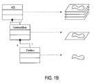
- Conventional VOI imaging architecturesmay utilize a three-tier representation structure: VOI-contourslice-contour.
- FIG. 1Billustrates the three-tier VOI structure in a Unified Modeling Language (UML) graph with a sample VOI.
- UMLUnified Modeling Language
- pathological anatomiese.g., a tumor
- target localizationi.e., accurate tracking of the position of the target
- soft tissue targetstend to move with patient breathing during radiation treatment delivery sessions.
- Respiratory motioncan move a pathological anatomy in the chest or abdomen, for example, by more than 3 centimeters (cm).
- cmcentimeters
- accurate delivery of the radiation beams to the pathological anatomy being treatedcan be critical, in order to achieve the radiation dose distribution that was computed during the treatment planning stage.
- Conventional methods for tracking anatomical motionutilize external markers and/or internal fiducial markers. Such conventional methods do not enable modeling of the anatomical change due to the respiratory cycle using conventional VOI imaging architectures. Moreover, such conventional methods do not take into account non-rigid motions and deformations of surrounding anatomy, as a function of motion cycle.
- FIG. 1Aillustrates a volume of interest defined by a stack of planar closed polygons.
- FIG. 1Billustrates a conventional three-tier VOI structure in a Unified Modeling Language (UML) graph with a sample VOI.
- UMLUnified Modeling Language
- FIG. 3illustrates one embodiment of a 4D VOI architecture, where the fourth dimension in the VOI architecture is a time dimension.
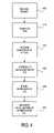
- FIG. 4illustrates one embodiment of generating a VOI using a 4D VOI architecture.
- FIG. 5illustrates of medical diagnostic imaging system implementing one embodiment of the present invention.
- FIG. 6illustrates one embodiment of a 4D mask volume.
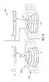
- FIG. 7illustrates a 2-dimensional perspective of radiation beams of a radiation treatment system directed at a target region according to a treatment plan.
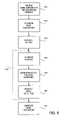
- FIG. 8is a flow chart illustrating one embodiment of generating a treatment plan using a 4D mask volume.
- Embodiments of the present inventioninclude various steps, which will be described below.
- the steps of the present inventionmay be performed by hardware components or may be embodied in machine-executable instructions, which may be used to cause a general-purpose or special-purpose processor programmed with the instructions to perform the steps.
- the stepsmay be performed by a combination of hardware and software.
- Embodiments of the present inventionmay be provided as a computer program product, or software, that may include a machine-readable medium having stored thereon instructions, which may be used to program a computer system (or other electronic devices) to perform a process.
- a machine-readable mediumincludes any mechanism for storing or transmitting information in a form (e.g., software, processing application) readable by a machine (e.g., a computer).
- the machine-readable mediummay include, but is not limited to, magnetic storage medium (e.g., floppy diskette); optical storage medium (e.g., CD-ROM); magneto-optical storage medium; read-only memory (ROM); random-access memory (RAM); erasable programmable memory (e.g., EPROM and EEPROM); flash memory; or other type of medium suitable for storing electronic instructions.
- magnetic storage mediume.g., floppy diskette
- optical storage mediume.g., CD-ROM
- magneto-optical storage mediume.g., magneto-optical storage medium
- ROMread-only memory
- RAMrandom-access memory
- EPROM and EEPROMerasable programmable memory
- flash memoryor other type of medium suitable for storing electronic instructions.
- Embodiments of the present inventionmay also be practiced in distributed computing environments where the machine-readable medium is stored on and/or executed by more than one computer system.
- the information transferred between computer systemsmay either be pulled or pushed across the communication medium connecting the computer systems, such as in a remote diagnosis or monitoring system.
- remote diagnosis or monitoringa user may utilize embodiments of the present invention to diagnose or monitor a patient despite the existence of a physical separation between the user and the patient.
- the methods and apparatusare discussed herein in relation to CT imaging only for ease of explanation.
- the method and apparatus discussed hereinmay also be used to generate VOIs from other types of medical diagnostic images (anatomical and/or functional), for example, magnetic resonance (MR), ultrasound (US), nuclear medicine (NM) PET/SPECT, etc.
- MRmagnetic resonance
- USultrasound
- NMnuclear medicine
- the “targets” discussed hereinmay be an anatomical feature(s) of a patient such as a pathological or normal anatomy and may include one or more non-anatomical reference structures.
- FIG. 2illustrates one embodiment of the acquisition of pre-treatment images (e.g., CT scans) of a changing target within a patient's anatomy.
- the target 211e.g., anatomical feature volume
- a deformationwhich may be a non-rigid deformation
- the target 211is described as moving periodically while undergoing a non-rigid deformation, any other type of motion (e.g. aperiodic motion) and any type of deformation or motion of the target may be accounted for.
- any other type of imaging modalitymay be used, for example, magnetic resonance imaging (MRI), positron emission tomography (PET), ultrasound, etc.
- CT scansare taken at different times points t i within, for example, a breathing cycle P 270 of a patient.
- the time points t icorrespond to different epochs in the patient breathing cycle, with, for example, t 0 ⁇ t 1 ⁇ t 2 .
- the cycle P 270may be monitored by an external sensor, for example, a breathing sensor, markers placed on the chest, etc.
- the CT images 221 , 222 , and 223are taken at time points t 0 , t 1 , and t 2 , respectively, containing the target 211 a , 211 b and 211 c at those respective time points.
- the epochs or time points within the breathing cycle P 270may be chosen to substantially encompass the overall dynamic range of the periodic motion 275 .
- the time pointsmay include: a time point t i corresponding to a trough of the cycle P; a time point t 2 corresponding to a peak of the cycle P; and a third time point t 0 disposed at an intermediate location between the peak and the trough of the cycle P 270 .
- the time points selected for taking the CT imagesmay include fewer or more than the three time points t 0 , t 1 , and t 2 described above. Accordingly, fewer or more than three CT images may be used.
- One way of providing a model for the continuous non-rigid deformation of the anatomy as a function of the motion cycleinvolves constructing a 4D mathematical model that morphs the CT image acquired at one instant or time point in the motion cycle into another CT image acquired at a subsequent instant or time point in the motion cycle.
- Any standard software and/or algorithm that is known and may be commercially availablecan be used to morph one image into another image, and to describe this in terms of a mathematical model.
- the 4D mathematical modelrelates the 3D locations of one or more reference structures (e.g., fiducals, skeletal structure, etc.) with the 3D locations of the target, as a function of the instant in the motion cycle.
- the 4D mathematical modelis applied to every voxel in one of the acquired CT images (e.g., CT image 222 ) to map the deformation of the target in each voxel of the CT image.
- CT image 222the acquired CT images
- such a 4D mathematical modelingmay require a lot of computing power and may be slower than desirable due the deformation mapping of each voxel in the CT image.
- a 4D VOImay be represented as a set ⁇ V 0 , V 1 , . . . , V k ⁇ where each V i is a 3D VOI representing a given point in time.
- such a 4D VOImay be created by generating a 3D VOI (V 0 ) in a 3D image I 0 .
- the first and second dimensions of the VOIcorrespond to one image slice in the 3D VOI and the third dimension corresponds to other slices in the 3D VOI. It should also be noted that the definitions of the first three dimensions could be the three axes of any coordinate system defined within the 3D image space.
- the corresponding VOIscould be formed by performing a non-rigid registration to determine the deformation mapping of image I 0 to image I i , and applying the deformation mapping to V 0 to give an initial estimate of V i .
- one or more additional refinement stepsmay be applied to V i , for example, a model-based refinement if V i represents an anatomical organ.
- a VOI representing any given point in timemay be formed by direct interpolation between V i and V i+1 , where i and i+1 are the VOIs immediately preceding and succeeding a desired point in time.
- This methodmay be much faster than having to interpolate the underlying deformation field itself and may result in a more efficient way of modeling tissue (e.g., organ) deformation over time.
- tissuee.g., organ
- the underlying deformation fieldmaps the space of image I i to the space of image I i+1 , hence if the deformation field is used directly to map between V i and V i+1 the underlying bit mask representation must be used (for example as described below in relation to FIG. 6 ).
- the 4D VOI architecturemay be used with a robotic based linear accelerator (LINAC) radiosurgery system (as discussed in further detail below) to supplement or supplant the robot motion tracking mechanisms that may already be present in such a system.
- LINACrobotic based linear accelerator
- the coordinate system in which each member of the VOI set is representedis arbitrary, a coordinate system may be chosen that is invariant with respect to the robotic-based LINAC. That is, the compensation for target change that would have otherwise been determined by the treatment delivery system for the robotic controlled LINAC during the treatment delivery is already predetermined by the treatment planning system using the 4D VOI architecture.
- FIG. 3illustrates one embodiment of a 4D VOI architecture, where the fourth dimension in the VOI architecture is a time dimension.
- the VOIis represented using a three-tier structure (VOI-contourslice-contour) in a UML graph with an example target.
- UMLis a graphical language for visualizing, specifying, constructing and documenting artifacts of a software-intensive system.
- the UMLoffers a standard way to write programming language statements, database schemas, and software components.
- UMLis well known in the art; accordingly, a more detailed discussion is not provided herein.
- each contour slice in VOI architecture 200may be restricted so that it contains only a simple (i.e. closed boundary with no holes or intersections) contour.
- contour slicesmay be created in non-adjacent slices, and interpolation used to create the contours in the intermediate slices.
- VOI architecture 200allows multiple contours to be defined for each contour slice. In this case, VOIs with cavities, branches, and unconnected bodies may be drawn. Alternatively, the methods described herein may also be used with other tiered (e.g., 4 tier) VOI architectures.
- VOI architecture 200includes a contour tier 210 , a contour slice (I i ) tier 220 , a VOI (V i ) tier 230 .
- the 4D VOI architecture 200may represented as a set ⁇ V 0 , V 1 , . . . , V k ⁇ where each of the V i is a 3D VOI representing a given point in time. Only three V i (V 0 235 a , V 1.5 , 235 b , and V 2 235 c ) are illustrated for ease of discussion purposes.
- the CT slices 221 and 223are taken at time points t i and t 2 , respectively, containing the target 211 in its state (e.g., position and deformation) at those respective time points 211 b and 211 c.
- FIG. 4illustrates one embodiment of generating a VOI using a 4D VOI architecture.
- the methodmay include receiving at least two 3D images I 1 222 and I 2 223 , step 405 , and generating at least two 3D VOIs (e.g., V 1 and V 2 ) with the at least two corresponding 3D images I 1 222 and I 2 223 , step 410 .
- a non-rigid registration of V i 235 b and V 2 235 cis performed. Registration may be performed using techniques known to those of ordinary skill in the art; accordingly, a detailed description of registration is not provided.
- a registration techniqueas described in “Hybrid point-and-intensity based deformable registration for abdominal CT images”, J. B. West, C. R. Maurer, Jr., and J. R. Dooley, Proc. SPIE vol. 5747, pp. 204-211, 2005, may be used.
- the output of the registration of step 420may be referred to as a deformation field.
- a deformation field relating two images, A and Bis a set of vectors defined such that in any position x in image A, the corresponding element of the deformation field, D(x), is a vector v such that the position (x+v) in image B describes the same anatomical location as x in image A.
- an interpolationmay be performed, using the registration results of step 420 , on V 1 235 b and V 2 235 c , step 430 .
- a VOI representing any given point in timemay be formed by direct interpolation between V i and V i+1 , where i and i+1 are the 3D VOIs immediately preceding and succeeding a desired point in time.
- a three-dimensional space deformation modelas described in “D. Bechmann and N. Dubreuil. Animation through space and time based on a space deformation model. The Journal of Visualization and Computer Animation. 4(3)165-184, 1993” may be used to generate the interpolated VOI.
- one or more additional refinementsmay be applied to V 1.5 236 such as a model-based refinement.
- a model-based refinementa model of V 1.5 236 is used to ensure that the contours describing V 1.5 236 give a valid shape for the organ being described by V 1.5 236 .
- the principal modes of variation of the boundary of V 1.5 236are stored as part of the model, and the contours of V 1.5 236 are refined so that their principal modes of variation are within given limits of those of the model.
- Refinement of a VOImay be performed either manually by the user (e.g., through a graphical user interface) or through the use of an algorithm that operates on the VOI.
- V 1.5 236may be used to generate a visualization of the VOI at time point t 1.5 , step 450 .
- the generation of a visualization from a VOIcould be achieved by rendering the mask volume of that VOI using volume rendering techniques as described in “Levoy, M., et. al, Volume Rendering in Radiation Treatment Planning, Proc. First Conference on Visualization in Biomedical Computing, IEEE Computer Society Press, Atlanta, Ga., May, 1990, pp. 4-10,” or by directly rendering the 3D geometrical structure of that VOI.
- the visualization(e.g., images 222 , 224 and 223 ) may be graphically displayed to a user to animate changing structures (e.g., image 211 ) faster and more accurate than may be possible when performing 4D mathematical modeling to map the underlying deformation field itself.
- FIG. 5illustrates one embodiment of medical diagnostic imaging system in which features of the present invention may be implemented.
- the medical diagnostic imaging systemmay be discussed below at times in relation to CT imaging modality only for ease of explanation. However, other imaging modalities may be used as previously mentioned.
- Medical diagnostic imaging system 700includes an imaging source 710 to generate a beam (e.g., kilo voltage x-rays, mega voltage x-rays, ultrasound, MRI, etc.) and an imager 720 to detect and receive the beam generated by imaging source 710 .
- system 700may include two diagnostic X-ray sources and/or two corresponding image detectors.
- two x-ray sourcesmay be nominally mounted angularly apart (e.g., 90 degrees apart or 45 degree orthogonal angles) and aimed through the patient toward the imager(s).
- a single large imager, or multiple imagers,can be used that would be illuminated by each x-ray imaging source.
- other numbers and configurations of imaging sources and imagersmay be used.
- the imaging source 710 and the imager 720are coupled to a digital processing system 730 to control the imaging operation.
- Digital processing system 730includes a bus or other means 735 for transferring data among components of digital processing system 730 .
- Digital processing system 730also includes a processing device 740 .
- Processing device 740may represent one or more general-purpose processors (e.g., a microprocessor), special purpose processor such as a digital signal processor (DSP) or other type of device such as a controller or field programmable gate array (FPGA).
- DSPdigital signal processor
- FPGAfield programmable gate array
- Processing device 740may be configured to execute the instructions for performing the operations and steps discussed herein.
- processing device 740may be configured to execute instructions to perform the Boolean operations on the contour sets 241 - 244 to define VOI 231 as discussed above with respect to FIG. 3 and to generate a VOI mask volume as discussed above with respect to FIG. 5 .
- Digital processing system 730may also include system memory 750 that may include a random access memory (RAM), or other dynamic storage device, coupled to bus 735 for storing information and instructions to be executed by processing device 740 .
- System memory 750also may be used for storing temporary variables or other intermediate information during execution of instructions by processing device 740 .
- System memory 750may also include a read only memory (ROM) and/or other static storage device coupled to bus 735 for storing static information and instructions for processing device 740 .
- ROMread only memory
- a storage device 760represents one or more storage devices (e.g., a magnetic disk drive or optical disk drive) coupled to bus 735 for storing information and instructions. Storage device 760 may be used for storing instructions for performing the steps discussed herein.
- storage device 760may be used for storing instructions for performing the steps discussed herein.
- Digital processing system 730may also be coupled to a display device 770 , such as a cathode ray tube (CRT) or liquid crystal display (LCD), for displaying information (e.g., image slice, animation of the target using the 4D VOI, etc.) to the user.
- a display device 770such as a cathode ray tube (CRT) or liquid crystal display (LCD)
- An input device 780such as a keyboard, may be coupled to digital processing system 730 for communicating information and/or command selections to processing device 740 .
- One or more other user input devices, such as a mouse, a trackball, or cursor direction keysfor communicating direction information and command selections to processing device 740 and for controlling cursor movement on display 770 may also be used.
- digital processing system 730represents only one example of a system, which may have many different configurations and architectures, and which may be employed with the present invention.
- some systemsoften have multiple buses, such as a peripheral bus, a dedicated cache bus, etc.
- the treatment planning systemmay share its database (e.g., stored in storage device 760 ) with a treatment delivery system, so that it is not necessary to export from the treatment planning system prior to treatment delivery.
- the treatment planning systemmay also include MIRIT (Medical Image Review and Import Tool) to support DICOM import (so images can be fused and targets delineated on different systems and then imported into the treatment planning system for planning and dose calculations), expanded image fusion capabilities that allow the user to treatment plan and view isodose distributions on any one of various imaging modalities (e.g., MRI, CT, PET, etc.).
- MIRITMedical Image Review and Import Tool
- the treatment delivery systemmay be an image guided robotic based linear accelerator (LINAC) radiation treatment (e.g., for performing radiosurgery) system, such as the CyberKnife® system developed by Accuray, Inc. of California.
- LINACimage guided robotic based linear accelerator
- the LINACis mounted on the end of a robotic arm having multiple (e.g., 5 or more) degrees of freedom in order to position the LINAC to irradiate the pathological anatomy with beams delivered from many angles in an operating volume (e.g., sphere) around the patient.
- Treatmentmay involve beam paths with a single isocenter, multiple isocenters, or with a non-isocentric approach (i.e., the beams need only intersect with the pathological target volume and do not necessarily converge on a single point, or isocenter, within the target).
- Treatmentcan be delivered in either a single session (mono-fraction) or in a small number of sessions (hypo-fractionation) as determined during treatment planning.
- Treatmentmay also be delivered without the use of a rigid external frame for performing registration of pre-operative position of the target during treatment planning to the intra-operative delivery of the radiation beams to the target according to the treatment plan.
- a gantry based (isocentric) intensity modulated radiotherapy (IMRT) systeme.g., a radiation source (e.g., a LINAC) is mounted on the gantry in such a way that it rotates in a plane corresponding to an axial slice of the patient. Radiation is then delivered from several positions on the circular plane of rotation.
- IMRTthe shape of the radiation beam is defined by a multi-leaf collimator that allows portions of the beam to be blocked, so that the remaining beam incident on the patient has a pre-defined shape.
- the resulting systemgenerates arbitrarily shaped radiation beams that intersect each other at the isocenter to deliver a dose distribution to the target.
- the optimization algorithmselects subsets of the main beam and determines the amount of time for which the subset of beams should be exposed, so that the dose constraints are best met.
- yet other types of treatment delivery systemsmay be used, for example, a stereotactic frame system such as the GammaKnife®, available from Elekta of Sweden.
- the optimization algorithmalso referred to as a sphere packing algorithm
- the optimization algorithmdetermines the selection and dose weighting assigned to a group of beams forming isocenters in order to best meet provided dose constraints.
- the 4D VOI architecture described hereinmay be used to perform inverse planning.
- Inverse planningin contrast to forward planning, allows the medical physicist to independently specify the minimum tumor dose and the maximum dose to other healthy tissues, and lets the treatment planning software select the direction, distance, and total number and energy of the beams.
- Conventional treatment planning software packagesare designed to import 3-D images from a diagnostic imaging source, for example, magnetic resonance imaging (MRI), positron emission tomography (PET) scans, angiograms and computerized x-ray tomography (CT) scans.
- MRImagnetic resonance imaging
- PETpositron emission tomography
- CTcomputerized x-ray tomography
- anatomical imaging modalitiessuch as CT are able to provide an accurate three-dimensional model of a volume of interest (e.g., skull or other tumor bearing portion of the body) generated from a collection of CT slices and, thereby, the volume requiring treatment can be visualized in three dimensions.
- a volume of intereste.g., skull or other tumor bearing portion of the body
- the VOI 230is used to delineate structures to be targeted or avoided with respect to the administered radiation dose. That is, the radiation source is positioned in a sequence calculated to localize the radiation dose into VOI 230 that as closely as possible conforms to the target (e.g., pathological anatomy such as a tumor) requiring treatment, while avoiding exposure of nearby healthy tissue.
- the targete.g., pathological anatomy such as a tumor
- the responsible radiation oncologist or medical physicistspecifies the minimum radiation dose to the target VOI and the maximum dose to normal and critical healthy tissue.
- the softwarethen produces the inverse treatment plan, relying on the positional capabilities of radiation treatment system, to meet the min/max dose constraints of the treatment plan.
- the 4D VOI architecture 200may be used to create a 4D mask volume, as discussed in further detail below. Hence, beams may be enabled or disabled depending the target's change over time. Although the change in target during treatment delivery may be different than the change in the target during treatment planning (e.g., due to differences in a patient's respiration at those different times), certain gross changes may be assumed to be similar. Accordingly, in one embodiment, the 4D VOI architecture 200 may be used to supplement (or possibly supplant) the robot motion tracking mechanisms that may otherwise be present in a robotic-based LINAC radiation treatment system, with finer changes handled by dynamic tracking capabilities of the treatment delivery system. Dynamic tracking is known in the art; accordingly a detailed description is not provided. Alternatively, the 4D VOI architecture 200 may be used to supplant the robot motion tracking mechanisms that may otherwise be present in a robotic-based LINAC radiation treatment system.
- each member of the setis represented is arbitrary, a coordinate system that is invariant with respect to the robot. That is, the compensation for target motion is already taking into account by the treatment planning software using the 4D VOI architecture 200 .
- FIG. 6illustrates one embodiment of a 4D mask volume.
- 4D mask volume 600is shown with two overlaid masks 635 b and 636 on V 1 235 b and V 1.5 236 , respectively, for times t i and t 1.5 , respectively.
- the VOI mask volumes 635 b and 636are volume representations of all user defined VOIs that are geometrically considered as a cuboid composed of many small cuboids of the same size (i.e., the voxels).
- every voxele.g., voxels 650 , 665 , etc.
- other number of bit wordsmay be used for a voxel.
- One bit, or more, of a voxelmay be used to represent if the voxel is covered by a VOI that is defined by the index of the bit.
- the bit valuewill be either a “1” or a “0” indicating whether a particular voxel is part of the target.
- a “1” bit valuemay be used to indicate a voxel is contained within the VOI represented by that mask position (as conceptually illustrated by the “1” for i th bit of voxel 665 of mask 635 b ).
- the treatment planning algorithmignores the dose constraints for that corresponding voxel.
- the VOI mask volumeserves as an interface between the VOI structures and the rest of an imaging system's functions such as, for examples, a 4-D VOI visualization and dose calculation in treatment planning.
- the radiation beams of a treatment delivery systemmay be enabled or disabled based on a target's change in position.
- the dose calculation process in the treatment planning algorithmconsiders a set of beams that are directed at the target region 211 .
- the treatment planning algorithmis used with a radiation source that has a collimator that defines the width of the set of beams that is produced. For each target 211 , for example, the number of beams, their sizes (e.g., as established by the collimator), their positions and orientations are determined. Having defined the position, orientation, and size of the beams to be used for planning, how much radiation should be delivered via each beam is also determined.
- the total amount of radiation exiting the collimator for one beamis defined in terms of Monitor Units (MU). Because the intensity of the radiation source is constant, the MU is linearly related to the amount of time for which the beam is enabled.
- Monitor UnitsMU
- the radiation dose absorbed (in units of cGy) by tissue in the path of the beamis also linearly related to the MU.
- the absorbed dose related to a beamis also affected by the collimator size of the beam, the amount of material between the collimator and the calculation point, the distance of the collimator from the calculation point, and the distance of the calculation point from the central axis of the beam.
- FIG. 7illustrates a 2-dimensional perspective of radiation beams of a radiation treatment system directed at a target region according to a treatment plan. It should be noted that 3 beams are illustrated in FIG. 7 only for ease of discussion and that an actual treatment plan may include more, or fewer, than 3 beams. Furthermore, although the 3 beams appear to intersect in the 2-dimensional perspective of FIG. 7 , the beams may not intersect in their actual 3-dimensional space. The radiation beams need only intersect with the target volume and do not necessarily converge on a single point, or isocenter, within the target. In one embodiment, using 4D mask volume 600 beams may be enabled or disabled based on the change in the target over time.
- FIG. 8is a flow chart illustrating one embodiment of generating a treatment plan using a 4D mask volume.
- the treatment planning algorithmreceives as input from a user, step 610 , the delineated target region 220 and any critical region 210 on one or more slices of a CT image; and (2) dose constraints defining the minimum and maximum doses for target region 220 and the maximum dose for the critical region 210 . It should be noted that additional dose constraints for additional regions may also be provided. The delineation of the regions and the dose constraints may be performed in any order.
- the treatment planning algorithmperforms beam weighting of each one or more beams of the radiation treatment system to be used in the treatment plan according to the inputs provided by the user above.
- the user or the treatment planning algorithmassigns an arbitrary weighting to each of one or more beams (e.g., beam 1 , beam 2 , beam 3 of FIG. 7 ) of the radiation treatment system.
- This weightingmay be determined using an algorithm designed to give a suitable “start point” for planning, may be randomly chosen, or may simply be a constant weighting for each beam.
- step 630the 4D VOI is generated and, in step 640 , the 4D mask volume is generated with the methods discussed above in relation to FIGS. 3 and 4 . If a voxel bit from a 4D volume mask 600 is a “0”, the planning algorithm ignores the dose constraints for that corresponding dose voxel for the particular point in time VOI. However, if a voxel bit from dose contour mask 400 has a “1” bit value for a particular point in time VOI, then determine whether any penalties should be accessed when performing beam weighting based on the dose constraints for that dose voxel, step 650 .
- the 4D volume maskmay be used so that if the 3D VOI at any of the time points has a “1” bit value at any position intersected by a beam, that beam is automatically set to have zero MU in the final plan.
- the following algorithmmay be used to perform beam weighting.
- step 660an assumption may be made that the size and trajectory of the beam set has been defined.
- the beam setbe ⁇ B i ; 1 ⁇ i ⁇ N ⁇ , where N ⁇ 500.
- Beam 1 , beam 2 , and beam 3illustrate in FIG. 7 have a respective weight 1 , weight 2 , weight 3 (i.e., a number of MU assigned to the beam, or how long a beam will be maintained on) associated with it.
- the weight in MU of each beamis designated by w i .
- the delineated regionsare represented as objects T j (derived from the 4D mask volume 600 ), with corresponding minimum and maximum allowed dose min j and max j , and critical structures (critical region 210 ) C j , with corresponding max j defined.
- Each regionhas an integer priority p j ⁇ [0,100] defining the relative importance of the dose constraints applied to that region.
- a 4D dose value maskis created.
- the 4D dose value maskmay be regarded as a set of 3D dose value masks, in the same way that a 4D VOI is a set of 3D VOIs.
- Each 3D dose value maskprovides a linked list of floating point values and positions d i (r,t) at a given point in time, where r is the position within the dose calculation volume, and di is the dose in cGy delivered to r by beam i when w i is set to unity, and t is the time, represented as a position in the respiratory cycle.
- ris the position within the dose calculation volume
- diis the dose in cGy delivered to r by beam i when w i is set to unity
- tis the time, represented as a position in the respiratory cycle.
- ⁇ i⁇ j ⁇ ⁇ r ⁇ T j ⁇ d i ⁇ ( r ) ⁇ d i ⁇ ( r ) , ( 2 )
- the beam valueis the ratio of dose delivered into target region 220 to total dose delivered.
- w i⁇ i , ⁇ i.
- D maxthe maximum dose within the dose calculation volume
- max jthe beam weights renormalized so that the new maximum dose is equal to the largest of the maximum dose constraints, max j .
- the optimization processlooks at all of the dose values in the dose volume and determine if the target region 211 and a critical region 610 are within the dose constraints. For example, suppose the dose in the target region 211 is specified to be equal to or greater than 2000 cGy and less than or equal to 2500 cGy. Suppose, the current dose value at grid location for voxel 665 of FIG. 6 is 1800 cGy, then the optimization process determines that, at the current beam weightings, the dose value at voxel 665 is 200 cGy short in order to satisfy the treatment plan constraints.
- the optimization processthen alters the beam weights so that the treatment solution is closer to meeting the provided dose constraints.
- a set of ⁇ w ithe amount by which each beam weight may be changed, is defined:
- the optimization processiterates through one or more of the beams and for each of the beams, if a beam weight is increased or decreased by a certain amount, determines the resulting dose distribution from such a change (i.e., how such a change alters the amount of violation of the treatment plan constraints). For example, an increase in one or more of the beam weights may typically help in achieving the constraint in the target (e.g., tumor) region but, depending on the location of the beam, it may also hurt in the critical region due to a possible resulting increase of dose above the maximum value in the critical region.
- a beam weightmay typically help in achieving the constraint in the target (e.g., tumor) region but, depending on the location of the beam, it may also hurt in the critical region due to a possible resulting increase of dose above the maximum value in the critical region.
- the optimization processtraverses the volume of interest, adds up all the penalties that are incurred by the increase in a beam weight, adds up all the penalties that are incurred by the decreasing the beam weight (e.g., under-dosing the target region), and then provides a result.
- a multipliermay be used with each penalty to stress the importance of one constraint (e.g., minimum dose value in the target region) versus another constraint (e.g., maximum dose value in the target region). For example, it may more important to achieve a minimum dose value than to stay under the maximum dose value in the target region.
- the optimization processthen updates the dose and goes on to the next beam and repeats the process until it has made its way through the beam set.
- the optimization processthen reaches a stage where it has looked at all of the different weights for each of the beams at the different dose levels and selects the beam weight that provides the optimal resulting dose values in both the target region and critical region.
- an iterative optimization processis used as follows: Iterate over the beams in decreasing order of ⁇ i . For each beam B j , calculate P j + and P j ⁇ , the relative penalties for respectively increasing or decreasing w j , that are defined as:
- the change in dose according to ⁇ w jis computed and applied to the dose volume before the optimization process moves on to a next beam, because a correct decision on how to change the beam weight assumes an up-to-date view of the dose including change sin previous w i . If all w j remained unchanged by the current iteration, s is reduced by a factor of 2.
- the optimization algorithmmay perform convex optimization via, for example, the Simplex algorithm, in an attempt to find an MU setting for all beams so that the dose constraints are nowhere violated.
- the Simplex algorithmis known in the art; accordingly, a detailed description is not provided.
- other iterative and non-iterative optimization algorithmsmay be used.
- the 4D VOI architecture 200may also be used with a mixed planning in which part of the treatment dose is generated by an isocenter placed using forward planning and part generated by individual beams during inverse planning.
- the methods and apparatus described hereinare not limited for use solely in treatment planning but may also be used independently for other applications, such as simulation and animation of object changes (e.g., deformation) over time.
- the methods and apparatus hereinmay be used outside of the medical technology field, such as non-destructive testing of materials (e.g., motor blocks in the automotive industry and drill cores in the petroleum industry) and seismic surveying.
Landscapes
- Engineering & Computer Science (AREA)
- Physics & Mathematics (AREA)
- General Physics & Mathematics (AREA)
- Theoretical Computer Science (AREA)
- Health & Medical Sciences (AREA)
- Radiology & Medical Imaging (AREA)
- Biomedical Technology (AREA)
- Computer Vision & Pattern Recognition (AREA)
- Computer Graphics (AREA)
- General Health & Medical Sciences (AREA)
- Nuclear Medicine, Radiotherapy & Molecular Imaging (AREA)
- Quality & Reliability (AREA)
- Veterinary Medicine (AREA)
- Multimedia (AREA)
- Pathology (AREA)
- Life Sciences & Earth Sciences (AREA)
- Animal Behavior & Ethology (AREA)
- Public Health (AREA)
- Medical Informatics (AREA)
- Computer Hardware Design (AREA)
- General Engineering & Computer Science (AREA)
- Software Systems (AREA)
- Apparatus For Radiation Diagnosis (AREA)
- Magnetic Resonance Imaging Apparatus (AREA)
- Ultra Sonic Daignosis Equipment (AREA)
Abstract
Description
Hence the total dose at r, summed over the entire respiratory cycle is,
and the total dose for beam i, summed over the entire respiratory cycle is,
wi=νisup(maxj)/Dmax. (3)
Δwj=Δwj+Δ(0)wj, (5)
- i else set:
Δwj=Δ(0)wj. (6)
- i else set:
Claims (28)
Priority Applications (2)
| Application Number | Priority Date | Filing Date | Title |
|---|---|---|---|
| US11/144,247US7352370B2 (en) | 2005-06-02 | 2005-06-02 | Four-dimensional volume of interest |
| PCT/US2006/021291WO2006130771A2 (en) | 2005-06-02 | 2006-06-01 | Four-dimensional volume of interest |
Applications Claiming Priority (1)
| Application Number | Priority Date | Filing Date | Title |
|---|---|---|---|
| US11/144,247US7352370B2 (en) | 2005-06-02 | 2005-06-02 | Four-dimensional volume of interest |
Publications (2)
| Publication Number | Publication Date |
|---|---|
| US20060274061A1 US20060274061A1 (en) | 2006-12-07 |
| US7352370B2true US7352370B2 (en) | 2008-04-01 |
Family
ID=37482320
Family Applications (1)
| Application Number | Title | Priority Date | Filing Date |
|---|---|---|---|
| US11/144,247Active2026-01-17US7352370B2 (en) | 2005-06-02 | 2005-06-02 | Four-dimensional volume of interest |
Country Status (2)
| Country | Link |
|---|---|
| US (1) | US7352370B2 (en) |
| WO (1) | WO2006130771A2 (en) |
Cited By (22)
| Publication number | Priority date | Publication date | Assignee | Title |
|---|---|---|---|---|
| US20070110294A1 (en)* | 2005-11-17 | 2007-05-17 | Michiel Schaap | Image enhancement using anisotropic noise filtering |
| US20090147916A1 (en)* | 2005-10-17 | 2009-06-11 | Fallone B Gino | Real-time dose reconstruction using dynamic simulation and image guided adaptive radiotherapy |
| US20090279784A1 (en)* | 2008-05-07 | 2009-11-12 | Microsoft Corporation | Procedural authoring |
| DE102008044901A1 (en)* | 2008-08-29 | 2010-03-04 | Siemens Aktiengesellschaft | Method and device for selecting an irradiation plan and irradiation facility |
| US20110050692A1 (en)* | 2009-09-01 | 2011-03-03 | Accuray Incorporated | Interpolating and rendering sub-phases of a 4d dataset |
| US20110110492A1 (en)* | 2005-07-25 | 2011-05-12 | Karl Otto | Methods and apparatus for the planning and delivery of radiation treatments |
| US20110170752A1 (en)* | 2008-02-25 | 2011-07-14 | Inventive Medical Limited | Medical training method and apparatus |
| US20110186755A1 (en)* | 2005-07-25 | 2011-08-04 | Karl Otto | Methods and apparatus for the planning and delivery of radiation treatments |
| US20130006093A1 (en)* | 2011-01-21 | 2013-01-03 | Headwater Partners Ii Llc | Radiation treatment with multiple imaging elements |
| US8433159B1 (en)* | 2007-05-16 | 2013-04-30 | Varian Medical Systems International Ag | Compressed target movement model using interpolation |
| US20140201670A1 (en)* | 2011-08-30 | 2014-07-17 | Koninklijke Philips N.V. | Integration of user inputs and correction of deformation vector field in deformable image registration workflow |
| US8792614B2 (en) | 2009-03-31 | 2014-07-29 | Matthew R. Witten | System and method for radiation therapy treatment planning using a memetic optimization algorithm |
| US9245336B2 (en) | 2010-12-15 | 2016-01-26 | Koninklijke Philips N.V. | Contour guided deformable image registration |
| US9468777B2 (en) | 2005-10-17 | 2016-10-18 | Alberta Health Services | Integrated external beam radiotherapy and MRI system |
| US9669236B2 (en) | 2011-01-21 | 2017-06-06 | Headwater Partners Ii Llc | Tracking of tumor location for targeted radiation treatment |
| US20180122150A1 (en)* | 2013-08-13 | 2018-05-03 | Boston Scientific Scimed, Inc. | Comparative analysis of anatomical items |
| USRE46953E1 (en) | 2007-04-20 | 2018-07-17 | University Of Maryland, Baltimore | Single-arc dose painting for precision radiation therapy |
| US10527700B2 (en)* | 2016-10-19 | 2020-01-07 | The Board Of Trustees Of The University Of Illinois | Multiband, multishot magnetic resonance elastography |
| US10551464B2 (en) | 2013-10-31 | 2020-02-04 | The Board Of Trustees Of The University Of Illinois | Three dimensional multislab, multi-shot magnetic resonance elastography |
| US10773101B2 (en) | 2010-06-22 | 2020-09-15 | Varian Medical Systems International Ag | System and method for estimating and manipulating estimated radiation dose |
| US20230097277A1 (en)* | 2021-09-29 | 2023-03-30 | Siemens Heal Thineers International Ag | On-line adaptive deep inspiration breath-hold treatment |
| US12008760B2 (en) | 2020-07-24 | 2024-06-11 | Covidien Lp | Systems and methods for estimating the movement of a target using a universal deformation model for anatomic tissue |
Families Citing this family (29)
| Publication number | Priority date | Publication date | Assignee | Title |
|---|---|---|---|---|
| US8989349B2 (en) | 2004-09-30 | 2015-03-24 | Accuray, Inc. | Dynamic tracking of moving targets |
| US20080021300A1 (en)* | 2006-06-29 | 2008-01-24 | Allison John W | Four-dimensional target modeling and radiation treatment |
| US7620147B2 (en) | 2006-12-13 | 2009-11-17 | Oraya Therapeutics, Inc. | Orthovoltage radiotherapy |
| US7535991B2 (en) | 2006-10-16 | 2009-05-19 | Oraya Therapeutics, Inc. | Portable orthovoltage radiotherapy |
| US8363783B2 (en) | 2007-06-04 | 2013-01-29 | Oraya Therapeutics, Inc. | Method and device for ocular alignment and coupling of ocular structures |
| US8506558B2 (en) | 2008-01-11 | 2013-08-13 | Oraya Therapeutics, Inc. | System and method for performing an ocular irradiation procedure |
| US7551717B2 (en)* | 2007-08-21 | 2009-06-23 | Wisconsin Alumni Research Foundation | Virtual 4D treatment suite |
| US8184886B2 (en)* | 2007-08-21 | 2012-05-22 | Siemens Aktiengesellschaft | Deformable 2D-3D registration |
| US7801271B2 (en) | 2007-12-23 | 2010-09-21 | Oraya Therapeutics, Inc. | Methods and devices for orthovoltage ocular radiotherapy and treatment planning |
| EP3272395B1 (en) | 2007-12-23 | 2019-07-17 | Carl Zeiss Meditec, Inc. | Devices for detecting, controlling, and predicting radiation delivery |
| US7720196B2 (en)* | 2008-01-07 | 2010-05-18 | Accuray Incorporated | Target tracking using surface scanner and four-dimensional diagnostic imaging data |
| US10311585B2 (en) | 2010-06-23 | 2019-06-04 | Varian Medical Systems International Ag | Mechanism for advanced structure generation and editing |
| CN103079467B (en)* | 2010-06-23 | 2016-06-29 | 瓦里安医疗系统国际股份公司 | Mechanisms for advanced structure generation and editing |
| US9283404B2 (en)* | 2011-01-21 | 2016-03-15 | Headwater Partners Ii Llc | Imaging observation timing for assisting radiation treatment |
| US9364687B2 (en) | 2011-01-21 | 2016-06-14 | Headwater Partners Ii Llc | Imaging observation timing based on radiation treatment system element delay |
| US10152951B2 (en) | 2011-02-28 | 2018-12-11 | Varian Medical Systems International Ag | Method and system for interactive control of window/level parameters of multi-image displays |
| DE102011075917B4 (en)* | 2011-05-16 | 2021-10-28 | Siemens Healthcare Gmbh | Method for providing a 3D image data set with suppressed measuring field exceedance artifacts and computer tomograph |
| CN105074778B (en)* | 2013-03-28 | 2018-10-12 | 皇家飞利浦有限公司 | Interactive follow-up visualization |
| CN113069691B (en)* | 2014-10-27 | 2023-08-15 | 医科达有限公司 | Image guidance for radiation therapy |
| US10137314B2 (en) | 2014-11-07 | 2018-11-27 | Raysearch Laboratories Ab | Robust radiotherapy treatment plan generation |
| EP3081262B1 (en) | 2015-04-14 | 2019-03-20 | RaySearch Laboratories AB | A method, a computer program product and a system for optimization of radiotherapy treatment planning |
| EP3228357B1 (en)* | 2016-04-08 | 2021-03-31 | RaySearch Laboratories AB | Method, computer program product and computer system for radiotherapy treatment planning |
| US11043042B2 (en)* | 2016-05-16 | 2021-06-22 | Hewlett-Packard Development Company, L.P. | Generating a shape profile for a 3D object |
| US10549117B2 (en)* | 2017-07-21 | 2020-02-04 | Varian Medical Systems, Inc | Geometric aspects of radiation therapy planning and treatment |
| US10245448B2 (en) | 2017-07-21 | 2019-04-02 | Varian Medical Systems Particle Therapy Gmbh | Particle beam monitoring systems and methods |
| US10843011B2 (en) | 2017-07-21 | 2020-11-24 | Varian Medical Systems, Inc. | Particle beam gun control systems and methods |
| US10092774B1 (en) | 2017-07-21 | 2018-10-09 | Varian Medical Systems International, AG | Dose aspects of radiation therapy planning and treatment |
| US10183179B1 (en) | 2017-07-21 | 2019-01-22 | Varian Medical Systems, Inc. | Triggered treatment systems and methods |
| US10609806B2 (en) | 2017-07-21 | 2020-03-31 | Varian Medical Systems Particle Therapy Gmbh | Energy modulation of a cyclotron beam |
Citations (56)
| Publication number | Priority date | Publication date | Assignee | Title |
|---|---|---|---|---|
| US4706296A (en)* | 1983-06-03 | 1987-11-10 | Fondazione Pro Juventute Don Carlo Gnocchi | Modularly expansible system for real time processing of a TV display, useful in particular for the acquisition of coordinates of known shape objects |
| US4788975A (en)* | 1987-11-05 | 1988-12-06 | Medilase, Inc. | Control system and method for improved laser angioplasty |
| US5359513A (en)* | 1992-11-25 | 1994-10-25 | Arch Development Corporation | Method and system for detection of interval change in temporally sequential chest images |
| US5384861A (en)* | 1991-06-24 | 1995-01-24 | Picker International, Inc. | Multi-parameter image display with real time interpolation |
| US5396418A (en)* | 1988-10-20 | 1995-03-07 | Picker International, Inc. | Four dimensional spiral volume imaging using fast retrace |
| US5633951A (en)* | 1992-12-18 | 1997-05-27 | North America Philips Corporation | Registration of volumetric images which are relatively elastically deformed by matching surfaces |
| US5798982A (en)* | 1996-04-29 | 1998-08-25 | The Trustees Of Columbia University In The City Of New York | Method for inverting reflection trace data from 3-D and 4-D seismic surveys and identifying subsurface fluid and pathways in and among hydrocarbon reservoirs based on impedance models |
| US5802220A (en) | 1995-12-15 | 1998-09-01 | Xerox Corporation | Apparatus and method for tracking facial motion through a sequence of images |
| US6139500A (en)* | 1999-02-24 | 2000-10-31 | Agilent Technologies Inc. | Methods and apparatus for 3D cardiac ultrasound imaging |
| US6169817B1 (en) | 1998-11-04 | 2001-01-02 | University Of Rochester | System and method for 4D reconstruction and visualization |
| US6307914B1 (en) | 1998-03-12 | 2001-10-23 | Mitsubishi Denki Kabushiki Kaisha | Moving body pursuit irradiating device and positioning method using this device |
| US20010048731A1 (en)* | 2000-06-01 | 2001-12-06 | Hironobu Nakamura | Imaging system and method of constructing image using the system |
| US20020054699A1 (en)* | 2000-09-26 | 2002-05-09 | Peter Roesch | Device and method of computing a transformation linking two images |
| US6438403B1 (en)* | 1999-11-01 | 2002-08-20 | General Electric Company | Method and apparatus for cardiac analysis using four-dimensional connectivity |
| US6466813B1 (en)* | 2000-07-22 | 2002-10-15 | Koninklijke Philips Electronics N.V. | Method and apparatus for MR-based volumetric frameless 3-D interactive localization, virtual simulation, and dosimetric radiation therapy planning |
| US6473634B1 (en)* | 2000-11-22 | 2002-10-29 | Koninklijke Philips Electronics N.V. | Medical imaging at two temporal resolutions for tumor treatment planning |
| US20020172407A1 (en)* | 2001-05-16 | 2002-11-21 | O'donnell Thomas | System for modeling static and dynamic three dimensional anatomical structures by 3-D models |
| US20020177770A1 (en)* | 1998-09-14 | 2002-11-28 | Philipp Lang | Assessing the condition of a joint and assessing cartilage loss |
| US6539074B1 (en)* | 2000-08-25 | 2003-03-25 | General Electric Company | Reconstruction of multislice tomographic images from four-dimensional data |
| US20030072479A1 (en)* | 2001-09-17 | 2003-04-17 | Virtualscopics | System and method for quantitative assessment of cancers and their change over time |
| US6563941B1 (en)* | 1999-12-14 | 2003-05-13 | Siemens Corporate Research, Inc. | Model-based registration of cardiac CTA and MR acquisitions |
| US20030142868A1 (en)* | 1999-04-15 | 2003-07-31 | Tannenbaum Allen Robert | Curvature based system for the segmentation and analysis of image data |
| US20030184291A1 (en)* | 2002-03-28 | 2003-10-02 | Rehwald Wolfgang G. | Shifting of artifacts by reordering of k-space |
| US20030228905A1 (en)* | 2002-06-07 | 2003-12-11 | Satoru Osako | Game system and game program |
| US6728424B1 (en) | 2000-09-15 | 2004-04-27 | Koninklijke Philips Electronics, N.V. | Imaging registration system and method using likelihood maximization |
| US20040081270A1 (en)* | 2002-10-25 | 2004-04-29 | Koninklijke Philips Electronics N.V. | Four-dimensional helical tomographic scanner |
| US6757423B1 (en)* | 1999-02-19 | 2004-06-29 | Barnes-Jewish Hospital | Methods of processing tagged MRI data indicative of tissue motion including 4-D LV tissue tracking |
| US20040138548A1 (en)* | 2003-01-13 | 2004-07-15 | Mediguide Ltd. | Method and system for registering a medical situation associated with a first coordinate system, in second coordinate system using an MPS system |
| US20040158145A1 (en)* | 2003-02-12 | 2004-08-12 | Siemens Medical Solutions Usa, Inc. | Verification of radiation beam characteristics |
| US20040258289A1 (en)* | 2003-04-15 | 2004-12-23 | Joachim Hornegger | Method for digital subtraction angiography using a volume dataset |
| US6835137B1 (en)* | 1998-08-06 | 2004-12-28 | Namco Limited | Game apparatus and communication game system |
| US20050027187A1 (en)* | 2003-07-23 | 2005-02-03 | Karl Barth | Process for the coupled display of intra-operative and interactively and iteratively re-registered pre-operative images in medical imaging |
| US20050053267A1 (en)* | 2003-09-05 | 2005-03-10 | Varian Medical Systems Technologies, Inc. | Systems and methods for tracking moving targets and monitoring object positions |
| US20050074145A1 (en)* | 2000-12-06 | 2005-04-07 | Microsoft Corporation | System and method providing improved head motion estimations for animation |
| US20050083332A1 (en)* | 2003-10-21 | 2005-04-21 | Industrial Technology Research Institute | Method to imitate lifelike images for computer deformed objects |
| US6892089B1 (en)* | 1999-04-22 | 2005-05-10 | Johns Hopkins University | Cardiac motion tracking using cine harmonic phase (HARP) magnetic resonance imaging |
| US20050111720A1 (en)* | 2003-11-25 | 2005-05-26 | Gurcan Metin N. | Shape estimates and temporal registration of lesions and nodules |
| US20050182316A1 (en)* | 2002-08-29 | 2005-08-18 | Burdette Everette C. | Method and system for localizing a medical tool |
| US20050261570A1 (en)* | 2001-06-08 | 2005-11-24 | Mate Timothy P | Guided radiation therapy system |
| US20060002630A1 (en)* | 2004-06-30 | 2006-01-05 | Accuray, Inc. | Fiducial-less tracking with non-rigid image registration |
| US20060002601A1 (en)* | 2004-06-30 | 2006-01-05 | Accuray, Inc. | DRR generation using a non-linear attenuation model |
| US20060020195A1 (en)* | 2004-07-20 | 2006-01-26 | Tony Falco | Verifying lesion characteristics using beam shapes |
| US6995763B2 (en)* | 1999-01-22 | 2006-02-07 | Cedara Software Corp. | Interactive sculpting for volumetric exploration and feature extraction |
| US20060074292A1 (en) | 2004-09-30 | 2006-04-06 | Accuray, Inc. | Dynamic tracking of moving targets |
| US20060072799A1 (en)* | 2004-08-26 | 2006-04-06 | Mclain Peter B | Dynamic contrast visualization (DCV) |
| US20060078183A1 (en)* | 2001-01-30 | 2006-04-13 | Decharms R C | Methods for physiological monitoring training, exercise and regulation |
| US7031504B1 (en)* | 2000-09-26 | 2006-04-18 | Vital Images, Inc. | Image data based retrospective temporal selection of medical images |
| US20060149522A1 (en)* | 2004-12-10 | 2006-07-06 | Dalin Tang | Image-based computational mechanical analysis and indexing for cardiovascular diseases |
| US20060182326A1 (en)* | 2005-01-20 | 2006-08-17 | Eastman Kodak Company | Radiation therapy method with target detection |
| US7107089B2 (en)* | 2000-06-01 | 2006-09-12 | Georgia Tech Research Corporation | Automated planning volume contouring algorithm for adjuvant brachytherapy treatment planning in sarcoma |
| US7154498B2 (en)* | 2003-09-10 | 2006-12-26 | Siemens Medical Solutions Usa, Inc. | System and method for spatio-temporal guidepoint modeling |
| US7218320B2 (en)* | 2003-03-13 | 2007-05-15 | Sony Corporation | System and method for capturing facial and body motion |
| US20070133848A1 (en)* | 2003-10-17 | 2007-06-14 | Mcnutt Todd R | Manual tools for model based image segmentation |
| US7280686B2 (en)* | 2002-05-29 | 2007-10-09 | Siemens Aktiengesellschaft | Computer-supported image reconstruction method for a three-dimensional subject |
| US7286866B2 (en)* | 2001-11-05 | 2007-10-23 | Ge Medical Systems Global Technology Company, Llc | Method, system and computer product for cardiac interventional procedure planning |
| US7295692B2 (en)* | 2002-12-06 | 2007-11-13 | Ge Medical Systems Global Technology Company, Llc | Process and apparatus for detection of the cardiac cycle |
- 2005
- 2005-06-02USUS11/144,247patent/US7352370B2/enactiveActive
- 2006
- 2006-06-01WOPCT/US2006/021291patent/WO2006130771A2/enactiveApplication Filing
Patent Citations (58)
| Publication number | Priority date | Publication date | Assignee | Title |
|---|---|---|---|---|
| US4706296A (en)* | 1983-06-03 | 1987-11-10 | Fondazione Pro Juventute Don Carlo Gnocchi | Modularly expansible system for real time processing of a TV display, useful in particular for the acquisition of coordinates of known shape objects |
| US4788975A (en)* | 1987-11-05 | 1988-12-06 | Medilase, Inc. | Control system and method for improved laser angioplasty |
| US4788975B1 (en)* | 1987-11-05 | 1999-03-02 | Trimedyne Inc | Control system and method for improved laser angioplasty |
| US5396418A (en)* | 1988-10-20 | 1995-03-07 | Picker International, Inc. | Four dimensional spiral volume imaging using fast retrace |
| US5384861A (en)* | 1991-06-24 | 1995-01-24 | Picker International, Inc. | Multi-parameter image display with real time interpolation |
| US5359513A (en)* | 1992-11-25 | 1994-10-25 | Arch Development Corporation | Method and system for detection of interval change in temporally sequential chest images |
| US5633951A (en)* | 1992-12-18 | 1997-05-27 | North America Philips Corporation | Registration of volumetric images which are relatively elastically deformed by matching surfaces |
| US5802220A (en) | 1995-12-15 | 1998-09-01 | Xerox Corporation | Apparatus and method for tracking facial motion through a sequence of images |
| US5798982A (en)* | 1996-04-29 | 1998-08-25 | The Trustees Of Columbia University In The City Of New York | Method for inverting reflection trace data from 3-D and 4-D seismic surveys and identifying subsurface fluid and pathways in and among hydrocarbon reservoirs based on impedance models |
| US6307914B1 (en) | 1998-03-12 | 2001-10-23 | Mitsubishi Denki Kabushiki Kaisha | Moving body pursuit irradiating device and positioning method using this device |
| US6835137B1 (en)* | 1998-08-06 | 2004-12-28 | Namco Limited | Game apparatus and communication game system |
| US20020177770A1 (en)* | 1998-09-14 | 2002-11-28 | Philipp Lang | Assessing the condition of a joint and assessing cartilage loss |
| US6169817B1 (en) | 1998-11-04 | 2001-01-02 | University Of Rochester | System and method for 4D reconstruction and visualization |
| US6995763B2 (en)* | 1999-01-22 | 2006-02-07 | Cedara Software Corp. | Interactive sculpting for volumetric exploration and feature extraction |
| US6757423B1 (en)* | 1999-02-19 | 2004-06-29 | Barnes-Jewish Hospital | Methods of processing tagged MRI data indicative of tissue motion including 4-D LV tissue tracking |
| US6139500A (en)* | 1999-02-24 | 2000-10-31 | Agilent Technologies Inc. | Methods and apparatus for 3D cardiac ultrasound imaging |
| US20030142868A1 (en)* | 1999-04-15 | 2003-07-31 | Tannenbaum Allen Robert | Curvature based system for the segmentation and analysis of image data |
| US6892089B1 (en)* | 1999-04-22 | 2005-05-10 | Johns Hopkins University | Cardiac motion tracking using cine harmonic phase (HARP) magnetic resonance imaging |
| US6438403B1 (en)* | 1999-11-01 | 2002-08-20 | General Electric Company | Method and apparatus for cardiac analysis using four-dimensional connectivity |
| US6563941B1 (en)* | 1999-12-14 | 2003-05-13 | Siemens Corporate Research, Inc. | Model-based registration of cardiac CTA and MR acquisitions |
| US20010048731A1 (en)* | 2000-06-01 | 2001-12-06 | Hironobu Nakamura | Imaging system and method of constructing image using the system |
| US7107089B2 (en)* | 2000-06-01 | 2006-09-12 | Georgia Tech Research Corporation | Automated planning volume contouring algorithm for adjuvant brachytherapy treatment planning in sarcoma |
| US6466813B1 (en)* | 2000-07-22 | 2002-10-15 | Koninklijke Philips Electronics N.V. | Method and apparatus for MR-based volumetric frameless 3-D interactive localization, virtual simulation, and dosimetric radiation therapy planning |
| US6539074B1 (en)* | 2000-08-25 | 2003-03-25 | General Electric Company | Reconstruction of multislice tomographic images from four-dimensional data |
| US6728424B1 (en) | 2000-09-15 | 2004-04-27 | Koninklijke Philips Electronics, N.V. | Imaging registration system and method using likelihood maximization |
| US7031504B1 (en)* | 2000-09-26 | 2006-04-18 | Vital Images, Inc. | Image data based retrospective temporal selection of medical images |
| US20020054699A1 (en)* | 2000-09-26 | 2002-05-09 | Peter Roesch | Device and method of computing a transformation linking two images |
| US6473634B1 (en)* | 2000-11-22 | 2002-10-29 | Koninklijke Philips Electronics N.V. | Medical imaging at two temporal resolutions for tumor treatment planning |
| US20050074145A1 (en)* | 2000-12-06 | 2005-04-07 | Microsoft Corporation | System and method providing improved head motion estimations for animation |
| US20060078183A1 (en)* | 2001-01-30 | 2006-04-13 | Decharms R C | Methods for physiological monitoring training, exercise and regulation |
| US20020172407A1 (en)* | 2001-05-16 | 2002-11-21 | O'donnell Thomas | System for modeling static and dynamic three dimensional anatomical structures by 3-D models |
| US20050261570A1 (en)* | 2001-06-08 | 2005-11-24 | Mate Timothy P | Guided radiation therapy system |
| US20030072479A1 (en)* | 2001-09-17 | 2003-04-17 | Virtualscopics | System and method for quantitative assessment of cancers and their change over time |
| US7286866B2 (en)* | 2001-11-05 | 2007-10-23 | Ge Medical Systems Global Technology Company, Llc | Method, system and computer product for cardiac interventional procedure planning |
| US20030184291A1 (en)* | 2002-03-28 | 2003-10-02 | Rehwald Wolfgang G. | Shifting of artifacts by reordering of k-space |
| US7280686B2 (en)* | 2002-05-29 | 2007-10-09 | Siemens Aktiengesellschaft | Computer-supported image reconstruction method for a three-dimensional subject |
| US20030228905A1 (en)* | 2002-06-07 | 2003-12-11 | Satoru Osako | Game system and game program |
| US20050182316A1 (en)* | 2002-08-29 | 2005-08-18 | Burdette Everette C. | Method and system for localizing a medical tool |
| US20040081270A1 (en)* | 2002-10-25 | 2004-04-29 | Koninklijke Philips Electronics N.V. | Four-dimensional helical tomographic scanner |
| US7295692B2 (en)* | 2002-12-06 | 2007-11-13 | Ge Medical Systems Global Technology Company, Llc | Process and apparatus for detection of the cardiac cycle |
| US20040138548A1 (en)* | 2003-01-13 | 2004-07-15 | Mediguide Ltd. | Method and system for registering a medical situation associated with a first coordinate system, in second coordinate system using an MPS system |
| US20040158145A1 (en)* | 2003-02-12 | 2004-08-12 | Siemens Medical Solutions Usa, Inc. | Verification of radiation beam characteristics |
| US7218320B2 (en)* | 2003-03-13 | 2007-05-15 | Sony Corporation | System and method for capturing facial and body motion |
| US20040258289A1 (en)* | 2003-04-15 | 2004-12-23 | Joachim Hornegger | Method for digital subtraction angiography using a volume dataset |
| US20050027187A1 (en)* | 2003-07-23 | 2005-02-03 | Karl Barth | Process for the coupled display of intra-operative and interactively and iteratively re-registered pre-operative images in medical imaging |
| US20050053267A1 (en)* | 2003-09-05 | 2005-03-10 | Varian Medical Systems Technologies, Inc. | Systems and methods for tracking moving targets and monitoring object positions |
| US7154498B2 (en)* | 2003-09-10 | 2006-12-26 | Siemens Medical Solutions Usa, Inc. | System and method for spatio-temporal guidepoint modeling |
| US20070133848A1 (en)* | 2003-10-17 | 2007-06-14 | Mcnutt Todd R | Manual tools for model based image segmentation |
| US20050083332A1 (en)* | 2003-10-21 | 2005-04-21 | Industrial Technology Research Institute | Method to imitate lifelike images for computer deformed objects |
| US7256787B2 (en)* | 2003-10-21 | 2007-08-14 | Jui-Hsin Hung | Method to imitate lifelike images for computer deformed objects |
| US20050111720A1 (en)* | 2003-11-25 | 2005-05-26 | Gurcan Metin N. | Shape estimates and temporal registration of lesions and nodules |
| US20060002601A1 (en)* | 2004-06-30 | 2006-01-05 | Accuray, Inc. | DRR generation using a non-linear attenuation model |
| US20060002630A1 (en)* | 2004-06-30 | 2006-01-05 | Accuray, Inc. | Fiducial-less tracking with non-rigid image registration |
| US20060020195A1 (en)* | 2004-07-20 | 2006-01-26 | Tony Falco | Verifying lesion characteristics using beam shapes |
| US20060072799A1 (en)* | 2004-08-26 | 2006-04-06 | Mclain Peter B | Dynamic contrast visualization (DCV) |
| US20060074292A1 (en) | 2004-09-30 | 2006-04-06 | Accuray, Inc. | Dynamic tracking of moving targets |
| US20060149522A1 (en)* | 2004-12-10 | 2006-07-06 | Dalin Tang | Image-based computational mechanical analysis and indexing for cardiovascular diseases |
| US20060182326A1 (en)* | 2005-01-20 | 2006-08-17 | Eastman Kodak Company | Radiation therapy method with target detection |
Non-Patent Citations (14)
| Title |
|---|
| Bartolozzi, F., De Gaetano, A., DiLena, E., Marino, S., Nieddu, L., Patrizi, G.: "Operational research techniques in medical treatment and diagnosis: a review." European Journal of Operations Research 121 (2000) pp. 435-466. |
| Cheek, S., Holder, A., Fuss, M. Salter, B.: "The relationship between the number of shots and the quality of Gamma Knife Radiosurgeries." Technical Report 84, Department of Mathematics, Trinity University, San Antonio, TX (2004). |
| D. Bechmann, N. Dubreuil, "Animation through space and time base don a space deformation model", The Journal of Visualization and Computer Animation, 4(3) 165-184, 1993. |
| Dantzig, G.B., Orden, A., Wolfe, P.: "The generalized Simplex method for minimizing a linear form under linear inequality restraints". Pacific Journal of Mathematics 5 (1955), pp. 183-195. |
| Ferris, M., Lim, J., Shepard, D.: "An optimization approach for the radiosurgery treatment planning", SIAM Journal on Optimization 13 (2003), pp. 921-937. |
| Holder, A., "A tutorial on radiation oncology and optimization", In Greenberg, H.J., ed.: Tutorials on Emerging Methodologies and Applications in Operations Research. Kluwer Academic Press (2004). |
| Holder, A.: "Radiotherapy treatment design and linear programming". Technical Report 70, Department of Mathematics, Trinity University, San Antonio, TX (2002). |
| Jay B. West, Calvin R. Maurer, Jr., John R. Dooley, Hybrid point-and-intensity-based deformable registration for abdominal CT images, Medical Imaging 2005: Image Processing, edited by J. Michael Fitzpatrick, Joseph M. Reinhardt, Proc. of SPIE vol. 5747, pp. 204-211. |
| Leksell, L., "The stereotactic method and radiosurgery of the brain", Acta Chirurgica Scandanavica 102 (1951), pp. 316-319. |
| M. Levoy, et al., "Volume Rendering in Radiation Treatment Planning", Proc. First Conference on Visualization in Biomedical Computing, IEEE Computer Society Press, Atlanta, Georgia, May 1990, pp. 4-10. |
| Paddick, I.: "A simple scoring ratio to index the conformality of radiosurgical treatment plans", Journal of Neurosurgery 93 (2000), pp. 219-222. |
| Rosen, I., Lane, R., Morrill, S., Belli, J.: "Treatment plan optimization using linear programming", Medical Physics 18 (1991), pp. 141-152. |
| Shepard, D., Ferris, M., Olivera, G., Mackie, T.: "Optimizing the delivery of radiation therapy to cancer patients", SIAM Review 41 (1999) pp. 721-744. |
| Torsten Rohlfing et al., "Modeling liver motion and deformation during the respiratory cycle using intensity-based nonrigid registration of gated MR images", Med. Phys. 31 (3), Mar. 2004, pp. 427-432. |
Cited By (50)
| Publication number | Priority date | Publication date | Assignee | Title |
|---|---|---|---|---|
| US9050459B2 (en) | 2005-07-25 | 2015-06-09 | Karl Otto | Methods and apparatus for the planning and delivery of radiation treatments |
| US11642027B2 (en) | 2005-07-25 | 2023-05-09 | Siemens Healthineers International Ag | Methods and apparatus for the planning and delivery of radiation treatments |
| US10595774B2 (en) | 2005-07-25 | 2020-03-24 | Varian Medical Systems International | Methods and apparatus for the planning and delivery of radiation treatments |
| US9788783B2 (en) | 2005-07-25 | 2017-10-17 | Varian Medical Systems International Ag | Methods and apparatus for the planning and delivery of radiation treatments |
| US9764159B2 (en) | 2005-07-25 | 2017-09-19 | Varian Medical Systems International Ag | Methods and apparatus for the planning and delivery of radiation treatments |
| US9687678B2 (en) | 2005-07-25 | 2017-06-27 | Varian Medical Systems International Ag | Methods and apparatus for the planning and delivery of radiation treatments |
| US20110110492A1 (en)* | 2005-07-25 | 2011-05-12 | Karl Otto | Methods and apparatus for the planning and delivery of radiation treatments |
| US9687674B2 (en) | 2005-07-25 | 2017-06-27 | Varian Medical Systems International Ag | Methods and apparatus for the planning and delivery of radiation treatments |
| US20110186755A1 (en)* | 2005-07-25 | 2011-08-04 | Karl Otto | Methods and apparatus for the planning and delivery of radiation treatments |
| US9687675B2 (en) | 2005-07-25 | 2017-06-27 | Varian Medical Systems International Ag | Methods and apparatus for the planning and delivery of radiation treatments |
| US9687676B2 (en) | 2005-07-25 | 2017-06-27 | Varian Medical Systems International Ag | Methods and apparatus for the planning and delivery of radiation treatments |
| US9687677B2 (en) | 2005-07-25 | 2017-06-27 | Varian Medical Systems International Ag | Methods and apparatus for the planning and delivery of radiation treatments |
| US8658992B2 (en)* | 2005-07-25 | 2014-02-25 | Karl Otto | Methods and apparatus for the planning and delivery of radiation treatments |
| US8696538B2 (en) | 2005-07-25 | 2014-04-15 | Karl Otto | Methods and apparatus for the planning and delivery of radiation treatments |
| US9687673B2 (en) | 2005-07-25 | 2017-06-27 | Varian Medical Systems International Ag | Methods and apparatus for the planning and delivery of radiation treatments |
| US9630025B2 (en) | 2005-07-25 | 2017-04-25 | Varian Medical Systems International Ag | Methods and apparatus for the planning and delivery of radiation treatments |
| US9468777B2 (en) | 2005-10-17 | 2016-10-18 | Alberta Health Services | Integrated external beam radiotherapy and MRI system |
| US20090147916A1 (en)* | 2005-10-17 | 2009-06-11 | Fallone B Gino | Real-time dose reconstruction using dynamic simulation and image guided adaptive radiotherapy |
| US8958528B2 (en) | 2005-10-17 | 2015-02-17 | Alberta Health Services | Real-time dose reconstruction using dynamic simulation and image guided adaptive radiotherapy |
| US8073102B2 (en)* | 2005-10-17 | 2011-12-06 | Alberta Health Services | Real-time dose reconstruction using dynamic simulation and image guided adaptive radiotherapy |
| US7660481B2 (en)* | 2005-11-17 | 2010-02-09 | Vital Images, Inc. | Image enhancement using anisotropic noise filtering |
| US20070110294A1 (en)* | 2005-11-17 | 2007-05-17 | Michiel Schaap | Image enhancement using anisotropic noise filtering |
| USRE46953E1 (en) | 2007-04-20 | 2018-07-17 | University Of Maryland, Baltimore | Single-arc dose painting for precision radiation therapy |
| US8433159B1 (en)* | 2007-05-16 | 2013-04-30 | Varian Medical Systems International Ag | Compressed target movement model using interpolation |
| US8917916B2 (en)* | 2008-02-25 | 2014-12-23 | Colin Bruce Martin | Medical training method and apparatus |
| US20110170752A1 (en)* | 2008-02-25 | 2011-07-14 | Inventive Medical Limited | Medical training method and apparatus |
| US9659406B2 (en) | 2008-05-07 | 2017-05-23 | Microsoft Technology Licensing, Llc | Procedural authoring |
| US10217294B2 (en) | 2008-05-07 | 2019-02-26 | Microsoft Technology Licensing, Llc | Procedural authoring |
| US8737721B2 (en)* | 2008-05-07 | 2014-05-27 | Microsoft Corporation | Procedural authoring |
| US20090279784A1 (en)* | 2008-05-07 | 2009-11-12 | Microsoft Corporation | Procedural authoring |
| DE102008044901A1 (en)* | 2008-08-29 | 2010-03-04 | Siemens Aktiengesellschaft | Method and device for selecting an irradiation plan and irradiation facility |
| US8792614B2 (en) | 2009-03-31 | 2014-07-29 | Matthew R. Witten | System and method for radiation therapy treatment planning using a memetic optimization algorithm |
| US20110050692A1 (en)* | 2009-09-01 | 2011-03-03 | Accuray Incorporated | Interpolating and rendering sub-phases of a 4d dataset |
| US10773101B2 (en) | 2010-06-22 | 2020-09-15 | Varian Medical Systems International Ag | System and method for estimating and manipulating estimated radiation dose |
| US11986671B2 (en) | 2010-06-22 | 2024-05-21 | Siemens Healthineers International Ag | System and method for estimating and manipulating estimated radiation dose |
| US9245336B2 (en) | 2010-12-15 | 2016-01-26 | Koninklijke Philips N.V. | Contour guided deformable image registration |
| US9669236B2 (en) | 2011-01-21 | 2017-06-06 | Headwater Partners Ii Llc | Tracking of tumor location for targeted radiation treatment |
| US8948842B2 (en)* | 2011-01-21 | 2015-02-03 | Headwater Partners Ii Llc | Radiation treatment with multiple imaging elements |
| US20130006093A1 (en)* | 2011-01-21 | 2013-01-03 | Headwater Partners Ii Llc | Radiation treatment with multiple imaging elements |
| US20140201670A1 (en)* | 2011-08-30 | 2014-07-17 | Koninklijke Philips N.V. | Integration of user inputs and correction of deformation vector field in deformable image registration workflow |
| US9336591B2 (en)* | 2011-08-30 | 2016-05-10 | Koninklijke Philips N.V. | Integration of user inputs and correction of deformation vector field in deformable image registration workflow |
| US11074760B2 (en)* | 2013-08-13 | 2021-07-27 | Boston Scientific Scimed, Inc. | Comparative analysis of anatomical items |
| US10796495B2 (en) | 2013-08-13 | 2020-10-06 | Boston Scientific Scimed, Inc. | Material analysis of anatomical items |
| US20180122150A1 (en)* | 2013-08-13 | 2018-05-03 | Boston Scientific Scimed, Inc. | Comparative analysis of anatomical items |
| US10551464B2 (en) | 2013-10-31 | 2020-02-04 | The Board Of Trustees Of The University Of Illinois | Three dimensional multislab, multi-shot magnetic resonance elastography |
| US11131738B2 (en) | 2016-10-19 | 2021-09-28 | The Board Of Trustees Of The University Of Illinois | Multiband, multishot magnetic resonance elastography |
| US10527700B2 (en)* | 2016-10-19 | 2020-01-07 | The Board Of Trustees Of The University Of Illinois | Multiband, multishot magnetic resonance elastography |
| US12008760B2 (en) | 2020-07-24 | 2024-06-11 | Covidien Lp | Systems and methods for estimating the movement of a target using a universal deformation model for anatomic tissue |
| US20230097277A1 (en)* | 2021-09-29 | 2023-03-30 | Siemens Heal Thineers International Ag | On-line adaptive deep inspiration breath-hold treatment |
| US11992705B2 (en)* | 2021-09-29 | 2024-05-28 | Siemens Healthineers International Ag | On-line adaptive deep inspiration breath-hold treatment |
Also Published As
| Publication number | Publication date |
|---|---|
| US20060274061A1 (en) | 2006-12-07 |
| WO2006130771A2 (en) | 2006-12-07 |
| WO2006130771A3 (en) | 2008-01-17 |
Similar Documents
| Publication | Publication Date | Title |
|---|---|---|
| US7352370B2 (en) | Four-dimensional volume of interest | |
| US11547870B2 (en) | Radiation treatment planning using four-dimensional imaging data | |
| US8406851B2 (en) | Patient tracking using a virtual image | |
| US8077936B2 (en) | Treatment planning software and corresponding user interface | |
| US7623679B2 (en) | Temporal smoothing of a deformation model | |
| US11382588B2 (en) | Non-invasive method for using 2D angiographic images for radiosurgical target definition | |
| US7298819B2 (en) | Flexible treatment planning | |
| US11596807B2 (en) | Partial deformation maps for reconstructing motion-affected treatment dose | |
| US7330578B2 (en) | DRR generation and enhancement using a dedicated graphics device | |
| WO2006130862A2 (en) | Generating a volume of interest using a dose isocontour | |
| US7894649B2 (en) | Target tracking using direct target registration | |
| US8588367B2 (en) | Motion compensation in quantitative data analysis and therapy | |
| US20080037843A1 (en) | Image segmentation for DRR generation and image registration | |
| US7801349B2 (en) | Automatic generation of an envelope of constraint points for inverse planning | |
| US20070003123A1 (en) | Precision registration of X-ray images to cone-beam CT scan for image-guided radiation treatment | |
| WO2006130863A2 (en) | Inverse planning using optimization constraints derived from image intensity | |
| US20110050692A1 (en) | Interpolating and rendering sub-phases of a 4d dataset |
Legal Events
| Date | Code | Title | Description |
|---|---|---|---|
| AS | Assignment | Owner name:ACCURAY INCORPORATED, CALIFORNIA Free format text:ASSIGNMENT OF ASSIGNORS INTEREST;ASSIGNORS:DOOLEY, JOHN R.;WEST, JAY B.;REEL/FRAME:017191/0188 Effective date:20050601 | |
| AS | Assignment | Owner name:ACCURAY INCORPORATED, CALIFORNIA Free format text:ASSIGNMENT OF ASSIGNORS INTEREST;ASSIGNOR:WANG, HONGWU;REEL/FRAME:016906/0924 Effective date:20050617 | |
| STCF | Information on status: patent grant | Free format text:PATENTED CASE | |
| FPAY | Fee payment | Year of fee payment:4 | |
| FPAY | Fee payment | Year of fee payment:8 | |
| AS | Assignment | Owner name:CERBERUS BUSINESS FINANCE, LLC, AS COLLATERAL AGENT, NEW YORK Free format text:ASSIGNMENT FOR SECURITY - PATENTS;ASSIGNORS:ACCURAY INCORPORATED;TOMOTHERAPY INCORPORATED;REEL/FRAME:037513/0170 Effective date:20160111 Owner name:CERBERUS BUSINESS FINANCE, LLC, AS COLLATERAL AGEN Free format text:ASSIGNMENT FOR SECURITY - PATENTS;ASSIGNORS:ACCURAY INCORPORATED;TOMOTHERAPY INCORPORATED;REEL/FRAME:037513/0170 Effective date:20160111 | |
| AS | Assignment | Owner name:MIDCAP FUNDING IV TRUST (AS SUCCESSOR BY ASSIGNMENT FROM MIDCAP FINANCIAL TRUST), MARYLAND Free format text:SECURITY INTEREST;ASSIGNORS:ACCURAY INCORPORATED;TOMOTHERAPY INCORPORATED;REEL/FRAME:042826/0358 Effective date:20170614 Owner name:TOMOTHERAPY INCORPORATED, CALIFORNIA Free format text:RELEASE BY SECURED PARTY;ASSIGNOR:CERBERUS BUSINESS FINANCE, LLC. AS COLLATERAL AGENT;REEL/FRAME:042821/0580 Effective date:20170614 Owner name:ACCURAY INCORPORATED, CALIFORNIA Free format text:RELEASE BY SECURED PARTY;ASSIGNOR:CERBERUS BUSINESS FINANCE, LLC. AS COLLATERAL AGENT;REEL/FRAME:042821/0580 Effective date:20170614 Owner name:MIDCAP FUNDING IV TRUST (AS SUCCESSOR BY ASSIGNMEN Free format text:SECURITY INTEREST;ASSIGNORS:ACCURAY INCORPORATED;TOMOTHERAPY INCORPORATED;REEL/FRAME:042826/0358 Effective date:20170614 | |
| AS | Assignment | Owner name:MIDCAP FINANCIAL TRUST, MARYLAND Free format text:SECURITY INTEREST;ASSIGNORS:ACCURAY INCORPORATED;TOMOTHERAPY INCORPORATED;REEL/FRAME:044910/0685 Effective date:20171215 | |
| AS | Assignment | Owner name:MIDCAP FUNDING IV TRUST, AS SUCCESSOR TO EXISTING Free format text:ASSIGNMENT OF SECURITY AGREEMENTS;ASSIGNOR:MIDCAP FUNDING X TRUST (AS SUCCESSOR BY ASSIGNMENT FROM MIDCAP FUNDING IV TRUST, AS SUCCESSOR BY ASSIGNMENT FROM MIDCAP FINANCIAL TRUST), AS EXISTING ADMINISTRATIVE AGENT;REEL/FRAME:048481/0804 Effective date:20190221 Owner name:MIDCAP FUNDING IV TRUST, AS SUCCESSOR TO EXISTING ADMINISTRATIVE AGENT, MARYLAND Free format text:ASSIGNMENT OF SECURITY AGREEMENTS;ASSIGNOR:MIDCAP FUNDING X TRUST (AS SUCCESSOR BY ASSIGNMENT FROM MIDCAP FUNDING IV TRUST, AS SUCCESSOR BY ASSIGNMENT FROM MIDCAP FINANCIAL TRUST), AS EXISTING ADMINISTRATIVE AGENT;REEL/FRAME:048481/0804 Effective date:20190221 | |
| MAFP | Maintenance fee payment | Free format text:PAYMENT OF MAINTENANCE FEE, 12TH YEAR, LARGE ENTITY (ORIGINAL EVENT CODE: M1553); ENTITY STATUS OF PATENT OWNER: LARGE ENTITY Year of fee payment:12 | |
| AS | Assignment | Owner name:SILICON VALLEY BANK, AS ADMINISTRATIVE AND COLLATERAL AGENT, CALIFORNIA Free format text:SECURITY INTEREST;ASSIGNORS:ACCURAY INCORPORATED;TOMOTHERAPY INCORPORATED;REEL/FRAME:056247/0001 Effective date:20210514 | |
| AS | Assignment | Owner name:ACCURAY INCORPORATED, CALIFORNIA Free format text:RELEASE BY SECURED PARTY;ASSIGNOR:MIDCAP FUNDING IV TRUST (AS SUCCESSOR BY ASSIGNMENT FROM MIDCAP FUNDING X TRUST, AS SUCCESSOR BY ASSIGNMENT FROM MIDCAP FUNDING IV TRUST, AS SUCCESSOR BY ASSIGNMENT FROM MIDCAP FINANCIAL TRUST);REEL/FRAME:056318/0559 Effective date:20210514 Owner name:TOMOTHERAPY INCORPORATED, CALIFORNIA Free format text:RELEASE BY SECURED PARTY;ASSIGNOR:MIDCAP FUNDING IV TRUST (AS SUCCESSOR BY ASSIGNMENT FROM MIDCAP FUNDING X TRUST, AS SUCCESSOR BY ASSIGNMENT FROM MIDCAP FUNDING IV TRUST, AS SUCCESSOR BY ASSIGNMENT FROM MIDCAP FINANCIAL TRUST);REEL/FRAME:056318/0559 Effective date:20210514 Owner name:ACCURAY INCORPORATED, CALIFORNIA Free format text:RELEASE BY SECURED PARTY;ASSIGNOR:MIDCAP FINANCIAL TRUST;REEL/FRAME:056318/0751 Effective date:20210514 Owner name:TOMOTHERAPY INCORPORATED, CALIFORNIA Free format text:RELEASE BY SECURED PARTY;ASSIGNOR:MIDCAP FINANCIAL TRUST;REEL/FRAME:056318/0751 Effective date:20210514 | |
| AS | Assignment | Owner name:ACCURAY INCORPORATED, WISCONSIN Free format text:RELEASE BY SECURED PARTY;ASSIGNOR:FIRST-CITIZENS BANK & TRUST COMPANY;REEL/FRAME:071638/0034 Effective date:20250606 | |
| AS | Assignment | Owner name:ACCURAY LLC, WISCONSIN Free format text:ASSIGNMENT OF ASSIGNORS INTEREST;ASSIGNOR:ACCURAY INCORPORATED;REEL/FRAME:072421/0584 Effective date:20250805 |