US7352091B2 - Electronic package for electrical machine - Google Patents
Electronic package for electrical machineDownload PDFInfo
- Publication number
- US7352091B2 US7352091B2US11/217,639US21763905AUS7352091B2US 7352091 B2US7352091 B2US 7352091B2US 21763905 AUS21763905 AUS 21763905AUS 7352091 B2US7352091 B2US 7352091B2
- Authority
- US
- United States
- Prior art keywords
- heat sink
- positive
- regulator
- negative
- diodes
- Prior art date
- Legal status (The legal status is an assumption and is not a legal conclusion. Google has not performed a legal analysis and makes no representation as to the accuracy of the status listed.)
- Expired - Fee Related, expires
Links
Images


Classifications
- H—ELECTRICITY
- H02—GENERATION; CONVERSION OR DISTRIBUTION OF ELECTRIC POWER
- H02K—DYNAMO-ELECTRIC MACHINES
- H02K5/00—Casings; Enclosures; Supports
- H02K5/04—Casings or enclosures characterised by the shape, form or construction thereof
- H02K5/16—Means for supporting bearings, e.g. insulating supports or means for fitting bearings in the bearing-shields
- H02K5/173—Means for supporting bearings, e.g. insulating supports or means for fitting bearings in the bearing-shields using bearings with rolling contact, e.g. ball bearings
- H02K5/1732—Means for supporting bearings, e.g. insulating supports or means for fitting bearings in the bearing-shields using bearings with rolling contact, e.g. ball bearings radially supporting the rotary shaft at both ends of the rotor
- H—ELECTRICITY
- H02—GENERATION; CONVERSION OR DISTRIBUTION OF ELECTRIC POWER
- H02K—DYNAMO-ELECTRIC MACHINES
- H02K11/00—Structural association of dynamo-electric machines with electric components or with devices for shielding, monitoring or protection
- H02K11/04—Structural association of dynamo-electric machines with electric components or with devices for shielding, monitoring or protection for rectification
- H02K11/049—Rectifiers associated with stationary parts, e.g. stator cores
- H02K11/05—Rectifiers associated with casings, enclosures or brackets
- H—ELECTRICITY
- H02—GENERATION; CONVERSION OR DISTRIBUTION OF ELECTRIC POWER
- H02K—DYNAMO-ELECTRIC MACHINES
- H02K11/00—Structural association of dynamo-electric machines with electric components or with devices for shielding, monitoring or protection
- H02K11/30—Structural association with control circuits or drive circuits
- H02K11/33—Drive circuits, e.g. power electronics
- H—ELECTRICITY
- H02—GENERATION; CONVERSION OR DISTRIBUTION OF ELECTRIC POWER
- H02K—DYNAMO-ELECTRIC MACHINES
- H02K19/00—Synchronous motors or generators
- H02K19/16—Synchronous generators
- H02K19/36—Structural association of synchronous generators with auxiliary electric devices influencing the characteristic of the generator or controlling the generator, e.g. with impedances or switches
- H02K19/365—Structural association of synchronous generators with auxiliary electric devices influencing the characteristic of the generator or controlling the generator, e.g. with impedances or switches with a voltage regulator
- H—ELECTRICITY
- H02—GENERATION; CONVERSION OR DISTRIBUTION OF ELECTRIC POWER
- H02K—DYNAMO-ELECTRIC MACHINES
- H02K5/00—Casings; Enclosures; Supports
- H02K5/04—Casings or enclosures characterised by the shape, form or construction thereof
- H02K5/20—Casings or enclosures characterised by the shape, form or construction thereof with channels or ducts for flow of cooling medium
- H02K5/207—Casings or enclosures characterised by the shape, form or construction thereof with channels or ducts for flow of cooling medium with openings in the casing specially adapted for ambient air
- H—ELECTRICITY
- H02—GENERATION; CONVERSION OR DISTRIBUTION OF ELECTRIC POWER
- H02K—DYNAMO-ELECTRIC MACHINES
- H02K9/00—Arrangements for cooling or ventilating
- H02K9/02—Arrangements for cooling or ventilating by ambient air flowing through the machine
- H02K9/04—Arrangements for cooling or ventilating by ambient air flowing through the machine having means for generating a flow of cooling medium
- H02K9/06—Arrangements for cooling or ventilating by ambient air flowing through the machine having means for generating a flow of cooling medium with fans or impellers driven by the machine shaft
Definitions
- This applicationrelates generally to an electrical apparatus. More specifically, this application relates to an electronic component package having a diode rectifier bridge, regulator, and brush holder assembly for a compact electrical machine having improved cooling characteristics.
- Rectification of the three-phase alternating currentis generally obtained by means of a rectifier bridge having between six and twelve power diodes depending on the application.
- Three of these diodes in a six diode configurationare the positive diodes, and are connected between the phase terminals of the stator windings of the alternator and the positive terminal B+ of the alternator which is connected to the battery and the electrical circuit of the vehicle.
- the diodesconstitute the rectifier bridge and are subjected to high current. Hence, it is necessary to cool them in the most effective way possible. To this end, it is known to install the diodes on metal carrier plates, which are located on the outside of the alternator and which constitute a dissipator for the heat produced by the diodes.
- the diodesare grouped on two carrier plates, one of which is reserved for the positive diodes, and the other for the negative diodes.
- the rectifier diodesare connected to respective metal carrier plates, and these carrier plates are used as heat sinks for these diodes as well.
- the rectifier diodesare inserted by pressure in receiving bore holes of the metal carrier plate or heat sink, or are soldered to the metal carrier plate using appropriate solder alloys.
- the end wires connected to the rectifier diodesenable the rectifier diodes to be connected to external sources.
- the heat sinksare typically constructed in the shape of a circle or crescent and are fastened in the same plane to the alternating current generator.
- bridge rectifiersmust not only be able to withstand normal battery charging current, but must also be able to supply current, perhaps as much as ten times the normal charging current.
- Bridge rectifiersare typically unable to absorb or conduct these types of excess currents and are also unable to rapidly dissipate the resulting heat.
- bridge rectifiersIn order for bridge rectifiers to handle these types of excessive currents and heat, it becomes necessary to utilize a bridge rectifier which has a higher current handling capability. Due to the space limitations of the alternating current generator, it then becomes very difficult to provide such a bridge rectifier from a feasibility standpoint as well as at an economical cost.
- Increasing the current capacity and heat dissipating characteristics of the bridge rectifierhas included mounting of semiconductor diode chips onto first and second metallic heat sinks which are electrically insulated from each other by a thin sheet of electrical insulating material. The diode chips are then covered by a protective insulating coating after connection to the respective heat sink.
- One of the metallic heat sinksincludes a finned area which is subjected to cooling air when the bridge rectifier is mounted to the generator.
- the heat sink with the plurality of finsincludes twelve air passages. This type of bridge rectifier is shown in U.S. Pat. No. 4,606,000 to Steele et al., incorporated herein by reference.
- an electronic packagethat can be used on small to large alternators (e.g., between about 114 mm to about 150+ mm stator diameter), six and twelve diode applications, and light duty and heavy duty applications. Moreover, there is a desire for an electronic package having a common footprint with a common layout and fastener locations.
- a rotor shaftis supported in a drive end frame assembly by a front bearing and in a slip ring end (SRE) frame assembly by a rear bearing.
- the rear bearingincludes an outer race fabricated of steel which is assembled with the slip ring end frame assembly fabricated of aluminum. Since steel and aluminum have different coefficients of thermal expansion (CTE), the fit between the outside diameter (OD) of the steel bearing and the inside diameter (ID) of the mating aluminum SRE frame housing the steel bearing changes with temperature.
- the size of the bearing OD and range of temperaturesare such that having a direct press-fit between the bearing and SRE frame assembly will result in either having a radial press that is too high, and hence stress at this interface, at one temperature extreme, or a completely loose fit at the other extreme.
- Another requirement of this interfaceis that it must allow the bearing outer race to move axially allowing relative axial movement of the steel rotor shaft relative to the aluminum housing.
- Plasticshave a greater coefficient of thermal expansion than aluminum and can effectively compensate for the radial mismatch between the aluminum and steel over the operating temperatures. Plastic, however, presents its own problems with respect to applied loads, elevated temperature, and time. Plastic creeps causing problems with radial alignment between the rear bearing and SRE frame assembly. Plastic also presents a thermal barrier to the outer race of the bearing preventing effective thermal conductance to the aluminum SRE frame assembly.
- the other approachincludes using a steel cup intermediate the bearing and the SRE frame assembly.
- the steel retaining cuptypically includes multiple legs extending radially outward. These legs are then attached to the SRE frame assembly through threaded fasteners or similar features. Although effective from a product standpoint, such an arrangement is costly.
- an electronic package for an electrical machineincluding a slip ring end (SRE) frame, having a first face and a second face, defining one end of a housing supporting a rotor therein so as to be rotatable; a plurality of negative diodes dispersed in an angular fashion in the SRE frame acting as a negative heat sink; a plurality of positive diodes mounted on a separate electrically conductive plate located adjacent a location of the plurality of negative diodes, the plate being configured as a positive heat sink having corresponding holes such that leads extending from each negative diode protrude directly therethrough and openings formed in the positive heat sink to engage a body of each positive diode; a non-conductive separator fitted over a series of bosses that space the positive heat sink above a top surface defining the negative heat sink, the separator configured to electrically insulate the positive heat sink and negative heat sink from one another; a terminal assembly configured to make appropriate electrical connections between the positive and negative diodes, stat
- an electronic package for an electrical machineincluding a slip ring end (SRE) frame defining one end of a housing configured for mounting a rotor therein so as to be rotatable, the SRE frame having a cast wall along an inside diameter; a plurality of slip rings positioned on the shaft; a plurality of negative diodes dispersed in an angular fashion in the SRE frame acting as a negative heat sink; a plurality of positive diodes mounted on a separate electrically conductive plate, having stamped fins on an outer diameter, located above a location of the plurality of negative diodes, the plate being configured as a positive heat sink having corresponding holes such that leads extending from each negative diode protrude directly therethrough and openings formed in the positive heat sink to engage a body of each positive diode; a non-conductive separator fitted over a series of bosses that space the positive heat sink above a top surface defining the negative heat sink, the separator configured to electrically insulate the positive heat sink and negative
- a bearing package for an electrical machineincluding a slip ring end (SRE) frame defining one end of a housing configured for mounting a rotor therein so as to be rotatable, said SRE frame having a bearing bore configured therein; a bearing having an outer race and an inner race, said inner race operably coupled with a rotor shaft of the rotor; and a steel retaining ring intermediate the bearing bore of the SRE frame and the outer race, the steel retaining ring retained in said bearing bore by one of spinning over and staking over a portion of an edge defining the bearing bore on a corresponding portion of an exposed edge defining the steel retaining ring.
- SREslip ring end
- FIG. 1is a sectional view of an electric machine for use in accordance with the present invention
- FIG. 2is the sectional view of an electric machine of FIG. 1 illustrating a twin internal fan configuration and airflow resulting therefrom in accordance with an exemplary embodiment
- FIG. 3includes a side view of regulator ( 42 ) a top plan view of an electronic package having regulator ( 42 ) and a side view of a stud connector removed from regulator ( 42 );
- FIG. 4illustrates various views of regulator ( 42 ) and brush holder ( 28 );
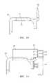
- FIG. 5is a top plan view of a positive heat sink without heat sink fins and a top plan view a positive heat sink with heat sink fins ( 52 );
- FIG. 6is a top plan view and a cross section view of a positive heat sink having a B+ stud ( 55 ) shown in axial and radial positions depicted with phantom lines;
- FIG. 7is a top plan view and a cross section of the positive heat sink of FIG. 6 illustrating a cover ( 90 ) operably coupled thereto;
- FIG. 8is a cross section view of a positive heat sink insulated from a negative heat sink perspective with a separator therebetween and secured with one another using a common fastener ( 56 );
- FIG. 9is a cross section view of the regulator of FIG. 4 illustrating opposing heat sinks defining opposing sides of the regulator;
- FIG. 10is an enlarged partial cross section view of a SRE frame illustrating a cast shield extending therefrom to isolate a slip ring region from electronic components of the electronic package;
- FIG. 11is an enlarged partial cross section view of the SRE frame of FIG. 10 with a brush holder in communication with slip rings ( 24 ) on a rotor shaft;
- FIGS. 12 and 13are perspective views of an assembled rectifier assembly having a positive and negative heat sink, terminal assembly, B+stud, brush holder and regulator;
- FIGS. 14 and 15includes a top plan view and a bottom perspective view, respectively, of the assembled rectifier assembly of FIGS. 13 and 14 illustrating cooling vents in the negative heat sink or SRE frame;
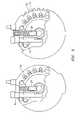
- FIG. 16is a cross section view of a SRE frame assembly including an outer race of a bearing retained therewith using a steel ring and an optional wave washer;
- FIG. 17is a top plan view of the SRE frame assembly of FIG. 16 illustrating a plurality of channels cast in the SRE frame circumferentially about the outer race to allow fresh air into a slip ring region.
- FIG. 1illustrates an exemplary rotor assembly 15 , containing several components including a shaft 14 , a field winding 3 surrounding a core (not shown), and pole segments 1 , disposed in an electric machine 10 that operates as an alternator in an exemplary embodiment, and is constructed by rotatably mounting a claw-pole rotor or the rotor assembly 15 by means of the shaft 14 inside a case 16 constituted by a front bracket or drive end frame 18 and a rear bracket or slip ring end (SRE) frame 20 , which may be made of aluminum, and fixing a stator 4 to an inner wall surface of the case 16 so as to cover an outer circumferential side of the rotor assembly 15 .
- This type of electric machineis shown in U.S. patent application Ser. No. 10/714,147, filed on Nov. 14, 2003, the contents of which are incorporated by reference herein in their entirety.
- the shaft 14is rotatably supported in the front bracket 18 via a first bearing 19 and the rear bracket 20 via a second bearing 21 .
- a pulley 22is fixed to a first end of this shaft 14 , enabling rotational torque from an engine to be transmitted to the shaft 14 by means of a belt (not shown).
- Slip rings 24 for supplying an electric current to the rotor assembly 15are fixed to a second end portion of the shaft 14 , a pair of brushes 26 being housed in a brush holder 28 disposed inside the case 16 so as to slide in contact with the slip rings 24 .
- a voltage regulator(not shown) for adjusting the magnitude of an alternating voltage generated in the stator 4 is operably coupled with the brush holder 28 .
- a first fan 34 and a second fan 36are fixed to first and second axial ends of the rotor assembly 15 .
- Front-end and rear-end air intake aperturesare disposed in axial end surfaces of the front bracket 18 and the rear bracket 20
- front-end and rear-end air discharge aperturesare disposed in first and second outer circumferential portions of the front bracket 18 and the rear bracket 20 preferably radially outside front-end and rear-end coil end groups of the armature winding 38 installed in the stator core 4 .
- the cooling arrangement thereofincludes a dual internal fan configuration, (i.e., fans 34 and 36 ).
- the first fan 34is placed on the drive end side of the rotor assembly 15 and the second fan 36 is placed on the slip ring end (SRE) side of the rotor assembly 15 .
- the fans 34 and 36are located within the housing 16 of the electric machine 10 and hence the dual internal fan designation.
- the drive end, or first, fan 34pulls air axially into the electric machine 10 generally shown with arrows 67 .
- airis drawn axially into the back of the electric machine 10 by the second fan 36 in an axial direction indicated generally with arrows 70 and then exhausts primarily in a radial direction indicated generally with arrows 70 ′.
- the present dual internal fan configuration described abovediminishes the airflow noise without reducing airflow to an undesirable level.
- the alternating current generator of the above constructionwhen the rotor 15 is rotated by an external driving force via pulley 22 , a magnetic field generated by the field winding 3 surrounding the field core, and the magnetic field passes through the stator winding 38 in conformance with the rotation of the rotor 15 . In this manner, current is generated in the stator winding 38 and a power is generated through rectifier 40 (shown in FIG. 3 ).
- the fans 34 and 36 fixed to the shaft 14are rotated together with the field core, and blades 76 defining cut-raised portions extending from the fans 34 and 36 , are also rotated to produce air flow inside the electric machine 10 .
- the air flowsmay be principally divided into flows 67 , 68 , 69 , and 69 ′ or flows 70 and 70 ′ as described above.
- Flows 67 , 68 , 69 , and 69 ′represent air flowing in through an inlet port 80 of front bracket 18 , passing through the coil end of the stator winding 38 , and splitting to exhaust primarily in a radial direction (i.e., 68 ) out of an outlet port 82 of the front bracket 18 and remaining portion of air flow continuing in an axial direction (i.e., 69 ) flowing out through an outlet port 84 of the rear bracket 16 .
- Flows 70 and 70 ′represent air flowing in through an inlet port 86 of rear bracket 16 , passing through the rectifier 40 and brush 26 , and flowing out through outlet port 84 of rear bracket 16 .
- the inside of the electric machine 10is cooled by these air flows.
- the heat produced within the electric machine 10is dependent upon the losses within the electric machine 10 which in turn is dependent upon the output.
- the cooling air flow rate produced by the fans 34 and 36is increased in proportion to the rpm while the wind noise is also increased.
- the temperature rise value of every part inside the electric machine 10 cooled by the fans 34 and 36is dependent upon a relation between the output and air flow rate.
- rectifier assembly 40configured for six to twelve diodes for converting alternating current (AC), produced by an electric machine, into direct current (DC) is shown.
- An electronic package layout for the electric machine 10is generally described.
- the electronic packageincludes rectifier assembly 40 , regulator assembly 42 , and a brush holder 28 .
- the rectifier 40includes the slip ring end (SRE) frame 20 of the electric machine 10 (not shown) having six negative diodes 44 disposed therewith.
- the SRE frame 20is preferably cast aluminum, but other materials are contemplated.
- the SRE frame 20includes a first face 33 and a second face 35 , as illustrated in FIG. 1 .
- the six negative diodes 44are mounted directly in contact with the SRE frame 20 of the electric machine 10 .
- the diodes 44are dispersed in an angular fashion and spaced from each other in a complementary configured aperture preferably allowing press-fit assembly.
- the SRE frame 20is configured as a structural, electrically and thermally conductive element (e.g., a negative heat sink) of the rectifier assembly 40 .
- a plurality of vents 46are concentrically disposed radially inward and outward of the diodes 44 forming an arc (as best seen in FIGS. 14 and 15 ) between diodes 44 .
- the plate 49is preferably configured as a positive heat sink having corresponding holes, such that leads extending from the negative diodes 44 protrude directly through a corresponding hole and are properly positioned with respect to a terminal assembly 50 for electrical connection therewith (as best seen in FIGS. 3 and 6 ).
- the plate 49may be configured with a plurality of fins 52 , illustrated in FIG. 5 , extending therefrom for cooling.
- the fins 52are stamped into an outside edge defining the plate 49 wherein all other features of the plate 49 remain the same as the non-finned embodiment of the plate 49 , which allows for the thermal capacity of the rectifier 40 to increase when used on larger machines with higher output currents without reconfiguring the electronics package.
- a cylindrical wall formed in the positive heat sink or plate 49 defining each corresponding holesurrounds each of the positive diodes 48 .
- the cylindrical wallis preferably configured to allow press-fit assembly of each of the corresponding positive diodes 48 therein.
- the cylindrical wallis optionally dimensioned and configured to increase the surface area of contact with the diode 48 to increase heat conduction from the diode 48 and increase heat dissipation from the cylindrical wall.
- the plate 49is preferably made of aluminum, and more preferably with 1100 aluminum alloy, however, other suitable conductive materials are also contemplated.
- a non-conductive separator 54is fitted over a series of bosses that space the plate 49 above a top surface defining the SRE frame 20 .
- the separator 54is configured as a phase lead insulator for the stator 4 (not shown) to insulate the stator 4 wires that protrude through the SRE frame 20 which is at ground potential.
- the separator 54which is a molded plastic component, electrically separates the plate 49 from ground, the negative diodes 44 that are pressed into the rear frame 20 , the positive diodes 48 that are pressed into the plate 49 , and a B+ stud 55 and a spacer 53 that are attached to the plate 49 in either a radial or axial orientation (see FIGS. 3 and 6 ).
- the terminal assembly 50is preferably configured in a circular arc fashion to match up with the curvature of the pattern of the disposed diodes 44 and 48 and the configuration of the plate 49 .
- a single-piece electrical conductor 51is preferably insert molded into the terminal assembly 50 .
- the electrical conductor 51is preferably copper, but other suitably conductive materials may be employed. After insert molding the terminal assembly 50 , it is stamped to separate the conductor 51 into appropriate sections for electrical connections with the diodes 44 and 48 , as well as the stator wires.
- the conductor 51is a ribbon type terminal assembly used for the stator 4 and the diodes 44 and 48 electrical connections, which affords a low cost solution.
- the terminal assembly 50 , the plate 49 , the separator 54 , and the SRE frame 20are clamped via common fasteners 56 (see FIG. 8 ) that pilot through a plurality of cylindrical walls 57 configured in the terminal assembly 50 securing the resulting assembly.
- Each of the cylindrical walls 57provides electrical isolation for the corresponding fastener 56 extending therethrough from the plate 49 .
- Each of the fasteners 56are directly engaged with the SRE frame 20 , such as for example threaded engagement where the fastener 56 is preferably a mechanical faster such as a threaded bolt, for example.
- One common fastener 56 used throughoutminimizes cost and the potential for error in the assembly plant where different fasteners can be mixed.
- the rectifier assembly 40is preferably cooled by multiple streams of air that flow across the plate 49 and the negative heat sink or the SRE frame 20 and through various air passages configured therein. Due to the plate 49 being spaced from the SRE frame 20 , air flows not only axially down through slots proximate the finned area defined by fins 52 on the plate 49 , but also flows radially across both faces defining the SRE frame 20 and the plate 49 before entering the SRE frame 20 inlet.
- the SRE frame 20is also cooled by this radial movement of air but then also by the radial movement of air within the SRE frame 20 as the air flows through the SRE frame 20 and across an inside face of the SRE frame 20 before exiting in a radial fashion.
- the fan 34 or 36illustrated in FIG. 1 , is preferably employed to increase airflow at the slip ring end of the electric machine.
- the fan 34 or 36is preferably configured to draw air into the SRE frame 20 toward the electronic package residing therein.
- the regulator assembly 42electrically connects to the plate 49 with a first terminal 58 extending therefrom illustrated in FIG. 3 , a stator phase field negative (F ⁇ ) terminal 61 (see FIG. 4 ) extending from terminal assembly 50 , the SRE frame 20 with terminal 59 extending therefrom and the brush holder assembly 28 via field positive (F+) terminal 60 .
- F ⁇stator phase field negative
- the regulator 42is structurally attached to the SRE frame 20 generally indicated at 61 and to the brush holder 28 . Inside the regulator 42 is an electronic circuit and devices that control the operation of the electric machine.
- the regulator 42is electrically connected to component wiring for signal type information through either a pinned connector body 62 that is integral with the regulator 42 or a stud type connection 63 disposed at one end that allows an external connector body to either plug into the regulator 42 or threadably engage the studs 63 for proper electrical interfacing.
- the regulator 42is electrically and structurally connected to the plate 49 that is at a battery B+ voltage potential.
- the metallic spacer 53is pressed over the B+ stud 55 .
- an external nut(not shown) is threadably fastened on the stud 55 .
- FIG. 9further illustrates a cross section view of the regulator 42 having a first side 97 , a second side 98 , and a heat sink 99 .
- the cover 90includes a plurality of vents 92 configured in a top surface defining the cover 90 to allow airflow therethrough to the electronic package disposed below the top surface.
- the cover 90may be directly attached to the SRE frame 20 by employing a snap fit feature.
- the cover 90is further configured having a cut away section generally indicated at 96 to allow the connector assembly 62 or 63 therethrough for electrical connection with an external connector body.
- the top surface of the cover 90is also configured having an aperture 94 to allow the spacer 53 and the B+ stud 55 to extend therethrough for electrical connection with a battery as discussed above.
- the above described inventionprovides a geometrical layout of the various components that yields a very effective thermal package for the rectifier and a structural design of the assembled components produces a very robust assembly resistant to the effects of vibration.
- the regulator 42 and the brush holder 28are, in their final configuration, attached to each other forming an integral body.
- the regulator 42is oriented such that the first side 97 faces away from the shaft 14 , and the second side 98 faces the brush holder 28 . Furthermore, the first side 97 and the second side 98 of the regulator 42 are both perpendicular to the first face 33 and to the second face 35 of the SRE frame 20 .
- the brush holder 28includes a plastic molded body 63 , two carbon brushes 26 with attached copper shunts 64 that connect to the regulator 42 via terminal 60 , two helical springs 65 to force the carbon brushes 26 in contact with rotating copper slip rings 24 located on the rotor 14 .
- the regulator 42 and the brush holder 28are fast to each other in a parallel back to back fashion such that the second face 98 of the regulator 42 mates to brush holder 28 and is equidistant from each of the helical springs 65 and carbon brushes 26 , thus minimizing interconnects there between and providing efficient space utilization. Furthermore the first face 97 and second face 98 of the regulator 42 are also parallel to and equidistant from the direction of brush travel.
- the brush holder 28is secured to the SRE frame 20 through a fastening screw 93 and through attachment to the regulator 28 .
- the fastening screw 93is dimensioned and configured as a common fastener 56 .
- the orientation of the regulator 42also allows for the regulator heat sink 99 to be put directly in the main air flow stream for cooling.
- the SRE frame 20 of the electric machineserves as a structural element, an electrical ground path for the rectifier 40 , and a heat sink for the rectifier 40 .
- the SRE frame 20also houses the rear bearing 21 of the electric machine.
- the SRE frame 20through a cast wall 39 , illustrated in FIGS. 10 and 11 , surrounding the slip rings 24 , provides shielding against external contaminants such as road splash for the slip rings 24 and brushes 26 , as well as heat sinking for the rear bearing 21 through the convective surfaces of the cast wall 39 .
- the internal fans 34 and 36provide for airflow along the convective surfaces of the cast wall 39 .
- the above described electronic packageprovides a single compact package for use with six and twelve diode configurations, and between light duty and heavy duty or off-road applications. Exemplary embodiments described herein further provide the flexibility to adapt the thermal cooling of the rectifier 40 or length of the brushes 26 to match a given application.
- the above described exemplary embodimentsuses low cost components and one common assembly footprint that can be common worldwide and used in six to twelve diode configurations. This will drive down direct material cost, tooling cost and intangible costs that are associated with having a common design and assembly process.
- the electronic package in accordance with exemplary embodimentsalso affords high thermal capability in comparison to other competitive designs.
- the rear bearing 21includes an outer race 102 that is retained in the SRE frame 20 of an electric machine.
- the SRE frame 20 of the electric machineis typically die cast aluminum while the rear bearing 21 (e.g., typically a deep groove ball bearing) is steel.
- the outer race 102is retained with the SRE frame 20 using a retaining ring 110 .
- the retaining ring 110is a steel, cylindrical shaped part that is inserted into a machined bearing bore 112 of the SRE frame 20 . After the ring 110 is inserted in the bore 112 , a portion 114 of the SRE frame 20 is either spun over or staked over to create a small lip 116 that retains one edge 118 defining the steel ring 110 . An opposite edge 120 defining the ring is retained by the geometry of a cast wall 122 of the SRE frame 20 .
- the steel ring 110is sized such that the outer race 102 of the bearing 21 is held sufficiently tight such that the outer race does not spin relative to the SRE frame 20 during electric machine use, but does allow for relative axial movements caused by the thermal expansion and contraction of the electric machine 10 .
- the retaining ring 110provides a low cost approach while maintaining long term dimensional stability and improved bearing heat dissipation.
- a plurality of cooling vents or channels 130are cast in bore 112 of the SRE frame 20 .
- the channels 130allow outside air to be pulled into the slip ring region 37 and then exit through these channels and into the cooling fans 36 .
- an optional wave washer 132can be added to the rear bearing assembly between the bottom of the cast bearing bore 112 in the SRE frame 20 and the outer race 102 of the bearing 21 .
- the wave washer 132functions to increase axial stiffness of the rotor/electric machine assembly and increase its natural frequency. On some applications, this is a desirable feature to reduce noise.
Landscapes
- Engineering & Computer Science (AREA)
- Power Engineering (AREA)
- Microelectronics & Electronic Packaging (AREA)
- Motor Or Generator Cooling System (AREA)
- Synchronous Machinery (AREA)
Abstract
Description
Claims (10)
Priority Applications (2)
| Application Number | Priority Date | Filing Date | Title |
|---|---|---|---|
| US11/217,639US7352091B2 (en) | 2004-09-01 | 2005-09-01 | Electronic package for electrical machine |
| US11/749,330US7417344B2 (en) | 2004-09-01 | 2007-05-16 | Electronic package for electrical machine |
Applications Claiming Priority (2)
| Application Number | Priority Date | Filing Date | Title |
|---|---|---|---|
| US60634804P | 2004-09-01 | 2004-09-01 | |
| US11/217,639US7352091B2 (en) | 2004-09-01 | 2005-09-01 | Electronic package for electrical machine |
Related Child Applications (1)
| Application Number | Title | Priority Date | Filing Date |
|---|---|---|---|
| US11/749,330DivisionUS7417344B2 (en) | 2004-09-01 | 2007-05-16 | Electronic package for electrical machine |
Publications (2)
| Publication Number | Publication Date |
|---|---|
| US20060043805A1 US20060043805A1 (en) | 2006-03-02 |
| US7352091B2true US7352091B2 (en) | 2008-04-01 |
Family
ID=36036872
Family Applications (2)
| Application Number | Title | Priority Date | Filing Date |
|---|---|---|---|
| US11/217,639Expired - Fee RelatedUS7352091B2 (en) | 2004-09-01 | 2005-09-01 | Electronic package for electrical machine |
| US11/749,330Expired - Fee RelatedUS7417344B2 (en) | 2004-09-01 | 2007-05-16 | Electronic package for electrical machine |
Family Applications After (1)
| Application Number | Title | Priority Date | Filing Date |
|---|---|---|---|
| US11/749,330Expired - Fee RelatedUS7417344B2 (en) | 2004-09-01 | 2007-05-16 | Electronic package for electrical machine |
Country Status (2)
| Country | Link |
|---|---|
| US (2) | US7352091B2 (en) |
| WO (1) | WO2006028981A2 (en) |
Cited By (40)
| Publication number | Priority date | Publication date | Assignee | Title |
|---|---|---|---|---|
| US20070011422A1 (en)* | 2005-07-11 | 2007-01-11 | General Electric Company | Hierarchical state based migration of structured data |
| US20070046114A1 (en)* | 2005-08-29 | 2007-03-01 | Denso Corporation | Automotive alternator with rectifier having high-strength heat sinks |
| US20110101803A1 (en)* | 2009-10-30 | 2011-05-05 | Mitsubishi Electric Corporation | Brushless rotary electric machine |
| US20110175495A1 (en)* | 2010-01-21 | 2011-07-21 | Remy International, Inc. | Electric machine with isolated ground electronics |
| US20110298316A1 (en)* | 2010-06-08 | 2011-12-08 | Bradfield Michael D | Electric Machine Cooling System and Method |
| US20110298318A1 (en)* | 2010-06-08 | 2011-12-08 | Bradfield Michael D | Gravity Fed Oil Cooling for an Electric Machine |
| US8395287B2 (en) | 2010-10-04 | 2013-03-12 | Remy Technologies, Llc | Coolant channels for electric machine stator |
| US8446056B2 (en) | 2010-09-29 | 2013-05-21 | Remy Technologies, Llc | Electric machine cooling system and method |
| US8482169B2 (en) | 2010-06-14 | 2013-07-09 | Remy Technologies, Llc | Electric machine cooling system and method |
| US8492952B2 (en) | 2010-10-04 | 2013-07-23 | Remy Technologies, Llc | Coolant channels for electric machine stator |
| US8497608B2 (en) | 2011-01-28 | 2013-07-30 | Remy Technologies, Llc | Electric machine cooling system and method |
| US8508085B2 (en) | 2010-10-04 | 2013-08-13 | Remy Technologies, Llc | Internal cooling of stator assembly in an electric machine |
| US8513840B2 (en) | 2010-05-04 | 2013-08-20 | Remy Technologies, Llc | Electric machine cooling system and method |
| US8519581B2 (en) | 2010-06-08 | 2013-08-27 | Remy Technologies, Llc | Electric machine cooling system and method |
| US8546982B2 (en) | 2011-07-12 | 2013-10-01 | Remy Technologies, Llc | Electric machine module cooling system and method |
| US8546983B2 (en) | 2010-10-14 | 2013-10-01 | Remy Technologies, Llc | Split drain system and method for an electric machine module |
| US8552600B2 (en) | 2010-06-14 | 2013-10-08 | Remy Technologies, Llc | Potted end turns of an electric machine |
| US8593021B2 (en) | 2010-10-04 | 2013-11-26 | Remy Technologies, Llc | Coolant drainage system and method for electric machines |
| US8614538B2 (en) | 2010-06-14 | 2013-12-24 | Remy Technologies, Llc | Electric machine cooling system and method |
| US8624452B2 (en) | 2011-04-18 | 2014-01-07 | Remy Technologies, Llc | Electric machine module cooling system and method |
| US8648506B2 (en) | 2010-11-09 | 2014-02-11 | Remy Technologies, Llc | Rotor lamination cooling system and method |
| US8659190B2 (en) | 2010-06-08 | 2014-02-25 | Remy Technologies, Llc | Electric machine cooling system and method |
| US8659191B2 (en) | 2010-05-18 | 2014-02-25 | Remy Technologies, Llc | Sleeve member for an electric machine |
| US8692425B2 (en) | 2011-05-10 | 2014-04-08 | Remy Technologies, Llc | Cooling combinations for electric machines |
| US8745847B2 (en) | 2011-11-17 | 2014-06-10 | Remy Technologies, L.L.C. | Method of P-forming a continuous conductor having a rectangular cross section and a stator including a stator winding formed from a P-formed conductor having a rectangular cross-section |
| US8789259B2 (en) | 2011-11-17 | 2014-07-29 | Remy Technologies, L.L.C. | Method of winding a stator core with a continuous conductor having a rectangular cross-section and a stator core |
| US8803380B2 (en) | 2011-06-03 | 2014-08-12 | Remy Technologies, Llc | Electric machine module cooling system and method |
| US8803381B2 (en) | 2011-07-11 | 2014-08-12 | Remy Technologies, Llc | Electric machine with cooling pipe coiled around stator assembly |
| US8901789B2 (en) | 2011-10-07 | 2014-12-02 | Remy Technologies, Llc | Electric machine module |
| US20150054363A1 (en)* | 2013-08-26 | 2015-02-26 | Mitsubishi Electric Corporation | Controller-integrated rotating electrical machine |
| US8975792B2 (en) | 2011-09-13 | 2015-03-10 | Remy Technologies, Llc | Electric machine module cooling system and method |
| US9041260B2 (en) | 2011-07-08 | 2015-05-26 | Remy Technologies, Llc | Cooling system and method for an electronic machine |
| US9048710B2 (en) | 2011-08-29 | 2015-06-02 | Remy Technologies, Llc | Electric machine module cooling system and method |
| US9054565B2 (en) | 2010-06-04 | 2015-06-09 | Remy Technologies, Llc | Electric machine cooling system and method |
| US9077218B2 (en) | 2012-02-24 | 2015-07-07 | Remy Technologies, Llc | Alternator brush holder |
| US9099900B2 (en) | 2011-12-06 | 2015-08-04 | Remy Technologies, Llc | Electric machine module cooling system and method |
| US9331543B2 (en) | 2012-04-05 | 2016-05-03 | Remy Technologies, Llc | Electric machine module cooling system and method |
| US9467010B2 (en) | 2011-11-17 | 2016-10-11 | Remy Technologies, L.L.C. | Method of winding a stator core with a continuous conductor having a rectangular cross-section and a stator core |
| US10069375B2 (en) | 2012-05-02 | 2018-09-04 | Borgwarner Inc. | Electric machine module cooling system and method |
| US20210167670A1 (en)* | 2018-07-27 | 2021-06-03 | Flender Gmbh | Holding device for a slip ring unit, slip ring bridge, slip ring unit, electric machine, and wind turbine |
Families Citing this family (23)
| Publication number | Priority date | Publication date | Assignee | Title |
|---|---|---|---|---|
| FR2849548B1 (en)* | 2002-10-25 | 2007-09-28 | Valeo Equip Electr Moteur | PROTECTIVE COVER FOR MOUNTING ON THE REAR BEARING OF A ROTATING, ALTERNATOR AND ALTERNO-STARTER ELECTRIC MACHINE COMPRISING SUCH A HOOD |
| JP2007135372A (en)* | 2005-11-14 | 2007-05-31 | Denso Corp | Ac power generator for vehicle |
| JP4849974B2 (en)* | 2006-06-27 | 2012-01-11 | 株式会社ジェイテクト | Brushless motor |
| US7876007B2 (en)* | 2006-07-14 | 2011-01-25 | Lybbert Justin B | Rectifier bridge assembly for an automotive application |
| DE102009024991B4 (en)* | 2009-06-16 | 2022-01-13 | Vorwerk & Co. Interholding Gmbh | Electric motor and method for assembling an electric motor |
| US8596151B2 (en)* | 2010-02-26 | 2013-12-03 | Honeywell International Inc. | Momentum exchange assemblies and inner gimbal assemblies for use in control moment gyroscopes |
| US8269384B2 (en)* | 2010-04-20 | 2012-09-18 | Remy Technologies, Llc | Alternator with dual axial air flow |
| EP2573240B1 (en)* | 2011-09-20 | 2015-05-27 | Groz-Beckert KG | High speed safety heald shaft |
| CA2779666C (en)* | 2012-06-04 | 2016-07-12 | Dale Benson | Brushless alternator |
| US9627948B2 (en) | 2014-04-11 | 2017-04-18 | Remy Technologies Llc | Electric machine with combined insulator and terminal assembly |
| US10715015B2 (en) | 2014-04-11 | 2020-07-14 | Borgwarner Inc. | Electric machine with combined insulator and terminal assembly |
| JP6213397B2 (en)* | 2014-07-03 | 2017-10-18 | 株式会社デンソー | Rotating electric machine |
| AU2014218391B2 (en)* | 2014-08-27 | 2019-05-30 | All-Tek Industrial Inc. | Brushless Alternator |
| JP5969571B2 (en)* | 2014-10-27 | 2016-08-17 | ファナック株式会社 | Electric motor that can prevent foreign matter from entering the housing |
| US10491081B2 (en) | 2014-11-21 | 2019-11-26 | Mitsubishi Electric Corporation | Automotive alternator |
| US10199908B2 (en)* | 2014-11-21 | 2019-02-05 | Mitsubishi Electric Corporation | Automotive alternator |
| JP6453658B2 (en)* | 2015-01-21 | 2019-01-16 | 株式会社マキタ | Electric tool |
| US10320262B2 (en)* | 2016-10-21 | 2019-06-11 | Borgwarner Inc. | Air cooled starter-generator |
| EP3320977B1 (en)* | 2016-11-14 | 2021-07-07 | Alfdex AB | Housing for a centrifugal separator |
| FR3065592B1 (en)* | 2017-04-20 | 2021-07-23 | Valeo Equip Electr Moteur | ROTATING ELECTRIC MACHINE EQUIPPED WITH A BEARING CONFIGURATION TO IMPROVE COOLING |
| CN107528425B (en)* | 2017-09-05 | 2024-06-21 | 江苏云意电气股份有限公司 | Rectifier W-end fixing structure for automobile generator |
| US12341392B2 (en)* | 2020-10-20 | 2025-06-24 | Schaeffler Technologies AG & Co. KG | Connection ring terminal, connection ring, and motor |
| US11831207B1 (en)* | 2022-05-10 | 2023-11-28 | Hamilton Sundstrand Corporation | Generator rotor assemblies |
Citations (10)
| Publication number | Priority date | Publication date | Assignee | Title |
|---|---|---|---|---|
| US3496394A (en)* | 1968-02-10 | 1970-02-17 | Bosch Gmbh Robert | Combined voltage regulator-brush holder unit for automotive type alternator |
| US4606000A (en) | 1985-03-27 | 1986-08-12 | General Motors Corporation | Bridge rectifier |
| JPH01286755A (en)* | 1988-05-13 | 1989-11-17 | Hitachi Ltd | Generator for vehicle |
| US5451823A (en)* | 1993-02-11 | 1995-09-19 | Transpo Electronics, Inc. | Vehicular thermoconductive lead frame rectifier assembly |
| US5744892A (en)* | 1995-09-06 | 1998-04-28 | Nippondenso Co., Ltd. | Brush and slip ring arrangement of an AC generator |
| US5780953A (en)* | 1993-12-07 | 1998-07-14 | Nippondenso Co., Ltd. | Alternator |
| US5977669A (en)* | 1995-11-08 | 1999-11-02 | Denso Corporation | Fastening means for contacting DC-output terminal with cooling fin in AC generator |
| US6664674B2 (en)* | 2000-04-14 | 2003-12-16 | Denso Corporation | Cooling structure of vehicle AC generator |
| US6754946B2 (en)* | 2002-08-26 | 2004-06-29 | Wetherill Associates, Inc. | Integrally formed rectifier for internal alternator regulator (IAR) style alternator |
| US20050006975A1 (en) | 2003-07-07 | 2005-01-13 | Bradfield Michael D. | Twin coil claw pole rotor with dual internal fan configuration for electrical machine |
Family Cites Families (7)
| Publication number | Priority date | Publication date | Assignee | Title |
|---|---|---|---|---|
| US3532402A (en)* | 1968-05-09 | 1970-10-06 | Burroughs Corp | Bearing mount |
| US4228210A (en)* | 1978-01-30 | 1980-10-14 | Trw Inc. | Plate or the like with serrated opening |
| US4429927A (en)* | 1981-04-06 | 1984-02-07 | Akira Kawabata | Casing having a mounting portion at its inner wall surface for receiving a bearing member therein |
| US5059042A (en)* | 1990-01-02 | 1991-10-22 | Whirlpool Corporation | Bearing retainer for a vacuum cleaner motor |
| US6486580B1 (en)* | 2000-02-10 | 2002-11-26 | Visteon Global Technologies, Inc. | Bearing retainer assembly |
| EP1382106A4 (en)* | 2001-03-16 | 2005-03-09 | Steven E Howe | Alternator and method of manufacture |
| JP3823920B2 (en)* | 2002-12-27 | 2006-09-20 | 三菱電機株式会社 | Electro-hydraulic power steering device |
- 2005
- 2005-09-01USUS11/217,639patent/US7352091B2/ennot_activeExpired - Fee Related
- 2005-09-01WOPCT/US2005/031347patent/WO2006028981A2/enactiveApplication Filing
- 2007
- 2007-05-16USUS11/749,330patent/US7417344B2/ennot_activeExpired - Fee Related
Patent Citations (10)
| Publication number | Priority date | Publication date | Assignee | Title |
|---|---|---|---|---|
| US3496394A (en)* | 1968-02-10 | 1970-02-17 | Bosch Gmbh Robert | Combined voltage regulator-brush holder unit for automotive type alternator |
| US4606000A (en) | 1985-03-27 | 1986-08-12 | General Motors Corporation | Bridge rectifier |
| JPH01286755A (en)* | 1988-05-13 | 1989-11-17 | Hitachi Ltd | Generator for vehicle |
| US5451823A (en)* | 1993-02-11 | 1995-09-19 | Transpo Electronics, Inc. | Vehicular thermoconductive lead frame rectifier assembly |
| US5780953A (en)* | 1993-12-07 | 1998-07-14 | Nippondenso Co., Ltd. | Alternator |
| US5744892A (en)* | 1995-09-06 | 1998-04-28 | Nippondenso Co., Ltd. | Brush and slip ring arrangement of an AC generator |
| US5977669A (en)* | 1995-11-08 | 1999-11-02 | Denso Corporation | Fastening means for contacting DC-output terminal with cooling fin in AC generator |
| US6664674B2 (en)* | 2000-04-14 | 2003-12-16 | Denso Corporation | Cooling structure of vehicle AC generator |
| US6754946B2 (en)* | 2002-08-26 | 2004-06-29 | Wetherill Associates, Inc. | Integrally formed rectifier for internal alternator regulator (IAR) style alternator |
| US20050006975A1 (en) | 2003-07-07 | 2005-01-13 | Bradfield Michael D. | Twin coil claw pole rotor with dual internal fan configuration for electrical machine |
Non-Patent Citations (1)
| Title |
|---|
| International Search Report, Application No. PCT/US05/31347, Date Mailed Sep. 26, 2007. |
Cited By (49)
| Publication number | Priority date | Publication date | Assignee | Title |
|---|---|---|---|---|
| US20070011422A1 (en)* | 2005-07-11 | 2007-01-11 | General Electric Company | Hierarchical state based migration of structured data |
| US20070046114A1 (en)* | 2005-08-29 | 2007-03-01 | Denso Corporation | Automotive alternator with rectifier having high-strength heat sinks |
| US7605502B2 (en)* | 2005-08-29 | 2009-10-20 | Denso Corporation | Automotive alternator with rectifier having high-strength heat sinks |
| US20110101803A1 (en)* | 2009-10-30 | 2011-05-05 | Mitsubishi Electric Corporation | Brushless rotary electric machine |
| US8400028B2 (en)* | 2009-10-30 | 2013-03-19 | Mitsubishi Electric Corporation | Brushless rotary electric machine |
| US8339000B2 (en) | 2010-01-21 | 2012-12-25 | Remy Technologies, Llc | Electric machine with isolated ground electronics |
| US20110175495A1 (en)* | 2010-01-21 | 2011-07-21 | Remy International, Inc. | Electric machine with isolated ground electronics |
| WO2011091148A1 (en)* | 2010-01-21 | 2011-07-28 | Remy Technologies, Llc | Electric machine with isolated ground electronics |
| US8513840B2 (en) | 2010-05-04 | 2013-08-20 | Remy Technologies, Llc | Electric machine cooling system and method |
| US8659191B2 (en) | 2010-05-18 | 2014-02-25 | Remy Technologies, Llc | Sleeve member for an electric machine |
| US9054565B2 (en) | 2010-06-04 | 2015-06-09 | Remy Technologies, Llc | Electric machine cooling system and method |
| US8269383B2 (en)* | 2010-06-08 | 2012-09-18 | Remy Technologies, Llc | Electric machine cooling system and method |
| US20110298318A1 (en)* | 2010-06-08 | 2011-12-08 | Bradfield Michael D | Gravity Fed Oil Cooling for an Electric Machine |
| US8456046B2 (en)* | 2010-06-08 | 2013-06-04 | Remy Technologies, Llc | Gravity fed oil cooling for an electric machine |
| US8659190B2 (en) | 2010-06-08 | 2014-02-25 | Remy Technologies, Llc | Electric machine cooling system and method |
| US20110298316A1 (en)* | 2010-06-08 | 2011-12-08 | Bradfield Michael D | Electric Machine Cooling System and Method |
| US8519581B2 (en) | 2010-06-08 | 2013-08-27 | Remy Technologies, Llc | Electric machine cooling system and method |
| US8482169B2 (en) | 2010-06-14 | 2013-07-09 | Remy Technologies, Llc | Electric machine cooling system and method |
| US8552600B2 (en) | 2010-06-14 | 2013-10-08 | Remy Technologies, Llc | Potted end turns of an electric machine |
| US8614538B2 (en) | 2010-06-14 | 2013-12-24 | Remy Technologies, Llc | Electric machine cooling system and method |
| US8446056B2 (en) | 2010-09-29 | 2013-05-21 | Remy Technologies, Llc | Electric machine cooling system and method |
| US8492952B2 (en) | 2010-10-04 | 2013-07-23 | Remy Technologies, Llc | Coolant channels for electric machine stator |
| US8395287B2 (en) | 2010-10-04 | 2013-03-12 | Remy Technologies, Llc | Coolant channels for electric machine stator |
| US8593021B2 (en) | 2010-10-04 | 2013-11-26 | Remy Technologies, Llc | Coolant drainage system and method for electric machines |
| US8508085B2 (en) | 2010-10-04 | 2013-08-13 | Remy Technologies, Llc | Internal cooling of stator assembly in an electric machine |
| US8546983B2 (en) | 2010-10-14 | 2013-10-01 | Remy Technologies, Llc | Split drain system and method for an electric machine module |
| US8648506B2 (en) | 2010-11-09 | 2014-02-11 | Remy Technologies, Llc | Rotor lamination cooling system and method |
| US8497608B2 (en) | 2011-01-28 | 2013-07-30 | Remy Technologies, Llc | Electric machine cooling system and method |
| US8624452B2 (en) | 2011-04-18 | 2014-01-07 | Remy Technologies, Llc | Electric machine module cooling system and method |
| US8692425B2 (en) | 2011-05-10 | 2014-04-08 | Remy Technologies, Llc | Cooling combinations for electric machines |
| US8803380B2 (en) | 2011-06-03 | 2014-08-12 | Remy Technologies, Llc | Electric machine module cooling system and method |
| US9041260B2 (en) | 2011-07-08 | 2015-05-26 | Remy Technologies, Llc | Cooling system and method for an electronic machine |
| US8803381B2 (en) | 2011-07-11 | 2014-08-12 | Remy Technologies, Llc | Electric machine with cooling pipe coiled around stator assembly |
| US8546982B2 (en) | 2011-07-12 | 2013-10-01 | Remy Technologies, Llc | Electric machine module cooling system and method |
| US9048710B2 (en) | 2011-08-29 | 2015-06-02 | Remy Technologies, Llc | Electric machine module cooling system and method |
| US8975792B2 (en) | 2011-09-13 | 2015-03-10 | Remy Technologies, Llc | Electric machine module cooling system and method |
| US8901789B2 (en) | 2011-10-07 | 2014-12-02 | Remy Technologies, Llc | Electric machine module |
| US9467010B2 (en) | 2011-11-17 | 2016-10-11 | Remy Technologies, L.L.C. | Method of winding a stator core with a continuous conductor having a rectangular cross-section and a stator core |
| US8789259B2 (en) | 2011-11-17 | 2014-07-29 | Remy Technologies, L.L.C. | Method of winding a stator core with a continuous conductor having a rectangular cross-section and a stator core |
| US8745847B2 (en) | 2011-11-17 | 2014-06-10 | Remy Technologies, L.L.C. | Method of P-forming a continuous conductor having a rectangular cross section and a stator including a stator winding formed from a P-formed conductor having a rectangular cross-section |
| US9099900B2 (en) | 2011-12-06 | 2015-08-04 | Remy Technologies, Llc | Electric machine module cooling system and method |
| US9484697B2 (en) | 2012-02-24 | 2016-11-01 | Remy Technologies, Llc | Alternator brush holder |
| US9077218B2 (en) | 2012-02-24 | 2015-07-07 | Remy Technologies, Llc | Alternator brush holder |
| US9331543B2 (en) | 2012-04-05 | 2016-05-03 | Remy Technologies, Llc | Electric machine module cooling system and method |
| US10069375B2 (en) | 2012-05-02 | 2018-09-04 | Borgwarner Inc. | Electric machine module cooling system and method |
| US20150054363A1 (en)* | 2013-08-26 | 2015-02-26 | Mitsubishi Electric Corporation | Controller-integrated rotating electrical machine |
| US9570962B2 (en)* | 2013-08-26 | 2017-02-14 | Mitsubishi Electric Corporation | Controller-integrated rotating electrical machine |
| US20210167670A1 (en)* | 2018-07-27 | 2021-06-03 | Flender Gmbh | Holding device for a slip ring unit, slip ring bridge, slip ring unit, electric machine, and wind turbine |
| US11664709B2 (en)* | 2018-07-27 | 2023-05-30 | Flender Gmbh | Holding apparatus for a slip ring unit, slip ring bridge, slip ring unit, electric machine, and wind turbine |
Also Published As
| Publication number | Publication date |
|---|---|
| WO2006028981A2 (en) | 2006-03-16 |
| WO2006028981A3 (en) | 2008-01-24 |
| US7417344B2 (en) | 2008-08-26 |
| US20060043805A1 (en) | 2006-03-02 |
| US20070210662A1 (en) | 2007-09-13 |
Similar Documents
| Publication | Publication Date | Title |
|---|---|---|
| US7352091B2 (en) | Electronic package for electrical machine | |
| KR100473101B1 (en) | Automotive alternator | |
| US6911750B2 (en) | Electronic package for electrical machine | |
| EP1394925B1 (en) | Automotive alternator having rectifier mounted on heatsink plate with cooling fins | |
| US6285100B1 (en) | Electrical machine, preferably a rotary current generator with a rectifier component and with upper heat sink provided with axial cooling fins | |
| KR100893657B1 (en) | Rotary electric machine | |
| US6198187B1 (en) | Automotive alternator | |
| EP1649099A1 (en) | Cleaning wipe and method of manufacture | |
| US6525438B1 (en) | Alternator | |
| US6882069B1 (en) | Vehicle AC generator with rectifier diode package disposed between cooling plates | |
| WO2016185510A1 (en) | Vehicle ac power generator | |
| US7741739B2 (en) | Automotive alternator | |
| JP4180385B2 (en) | Rotating electrical equipment | |
| EP1460750B1 (en) | AC generator for vehicles | |
| KR100363815B1 (en) | Alternator | |
| US20070040531A1 (en) | Alternator rectifier | |
| US20100213775A1 (en) | High power density generator | |
| JP3543876B2 (en) | Alternator | |
| US20090045686A1 (en) | Heat Pipe-Equipped Cooling Device for a Rotating Electric Machine | |
| JP3972768B2 (en) | AC generator | |
| EP1357659B1 (en) | Automotive alternator | |
| KR20000001105U (en) | Slip ring end frame for alternator. | |
| JP2003299313A (en) | AC generator for vehicles |
Legal Events
| Date | Code | Title | Description |
|---|---|---|---|
| AS | Assignment | Owner name:REMY INTERNATIONAL, INC., INDIANA Free format text:ASSIGNMENT OF ASSIGNORS INTEREST;ASSIGNOR:BRADFIELD, MICHAEL D.;REEL/FRAME:016947/0428 Effective date:20050831 | |
| AS | Assignment | Owner name:BARCLAYS BANK PLC, AS ADMINISTRATIVE AGENT, NEW YO Free format text:SECURITY AGREEMENT (REVOLVER);ASSIGNOR:REMY INTERNATIONAL, INC.;REEL/FRAME:020064/0206 Effective date:20071010 Owner name:BARCLAYS BANK PLC, AS ADMINISTRATIVE AGENT,NEW YOR Free format text:SECURITY AGREEMENT (REVOLVER);ASSIGNOR:REMY INTERNATIONAL, INC.;REEL/FRAME:020064/0206 Effective date:20071010 | |
| AS | Assignment | Owner name:BARCLAYS BANK PLC, AS ADMINISTRATIVE AGENT, NEW YO Free format text:SECURITY AGREEMENT (FIRST LIEN);ASSIGNOR:REMY INTERNATIONAL, INC.;REEL/FRAME:020056/0141 Effective date:20071010 Owner name:BARCLAYS BANK PLC, AS ADMINISTRATIVE AGENT,NEW YOR Free format text:SECURITY AGREEMENT (FIRST LIEN);ASSIGNOR:REMY INTERNATIONAL, INC.;REEL/FRAME:020056/0141 Effective date:20071010 | |
| AS | Assignment | Owner name:REMY INTERNATIONAL, INC., INDIANA Free format text:RELEASE BY SECURED PARTY;ASSIGNOR:WACHOVIA CAPITAL FINANCE CORPORATION (CENTRAL) (FORMERLY KNOW AS CONGRESS FINANCIAL CORPORATION (CENTRAL));REEL/FRAME:020196/0553 Effective date:20071201 | |
| AS | Assignment | Owner name:BARCLAYS BANK PLC, AS ADMINISTRATIVE AGENT, NEW YO Free format text:SECURITY AGREEMENT (REVOLVER);ASSIGNOR:REMY TECHNOLOGIES, L.L.C.;REEL/FRAME:020261/0460 Effective date:20071205 Owner name:REMY TECHNOLOGIES, L.L.C., INDIANA Free format text:ASSIGNMENT OF ASSIGNORS INTEREST;ASSIGNOR:REMY INTERNATIONAL, INC.;REEL/FRAME:020261/0563 Effective date:20071204 Owner name:BARCLAYS BANK PLC, AS ADMINISTRATIVE AGENT,NEW YOR Free format text:SECURITY AGREEMENT (REVOLVER);ASSIGNOR:REMY TECHNOLOGIES, L.L.C.;REEL/FRAME:020261/0460 Effective date:20071205 Owner name:REMY TECHNOLOGIES, L.L.C.,INDIANA Free format text:ASSIGNMENT OF ASSIGNORS INTEREST;ASSIGNOR:REMY INTERNATIONAL, INC.;REEL/FRAME:020261/0563 Effective date:20071204 | |
| AS | Assignment | Owner name:BARCLAYS BANK PLC, AS ADMINISTRATIVE AGENT, NEW YO Free format text:SECURITY AGREEMENT (FIRST LIEN);ASSIGNOR:REMY TECHNOLOGIES, L.L.C.;REEL/FRAME:020261/0583 Effective date:20071205 Owner name:BARCLAYS BANK PLC, AS ADMINISTRATIVE AGENT,NEW YOR Free format text:SECURITY AGREEMENT (FIRST LIEN);ASSIGNOR:REMY TECHNOLOGIES, L.L.C.;REEL/FRAME:020261/0583 Effective date:20071205 | |
| AS | Assignment | Owner name:BARCLAYS BANK PLC, AS ADMINISTRATIVE AGENT, NEW YO Free format text:SECURITY AGREEMENT (SECOND LIEN);ASSIGNOR:REMY TECHNOLOGIES, L.L.C.;REEL/FRAME:020270/0951 Effective date:20071205 Owner name:BARCLAYS BANK PLC, AS ADMINISTRATIVE AGENT,NEW YOR Free format text:SECURITY AGREEMENT (SECOND LIEN);ASSIGNOR:REMY TECHNOLOGIES, L.L.C.;REEL/FRAME:020270/0951 Effective date:20071205 | |
| AS | Assignment | Owner name:THE BANK OF NEW YORK TRUST COMPANY, N.A., ILLINOIS Free format text:SECURITY AGREEMENT;ASSIGNORS:REMY INTERNATIONAL, INC.;WESTERN REMAN INDUSTRIAL, INC.;M. & M. KNOPF AUTO PARTS, L.L.C.;AND OTHERS;REEL/FRAME:020540/0381 Effective date:20071206 Owner name:THE BANK OF NEW YORK TRUST COMPANY, N.A.,ILLINOIS Free format text:SECURITY AGREEMENT;ASSIGNORS:REMY INTERNATIONAL, INC.;WESTERN REMAN INDUSTRIAL, INC.;M. & M. KNOPF AUTO PARTS, L.L.C.;AND OTHERS;REEL/FRAME:020540/0381 Effective date:20071206 | |
| AS | Assignment | Owner name:REMY INTERNATIONAL, INC., INDIANA Free format text:RELEASE BY SECURED PARTY;ASSIGNOR:DEUTSCHE BANK NATIONAL TRUST COMPANY;REEL/FRAME:020353/0212 Effective date:20071205 Owner name:REMY INTERNATIONAL, INC.,INDIANA Free format text:RELEASE BY SECURED PARTY;ASSIGNOR:DEUTSCHE BANK NATIONAL TRUST COMPANY;REEL/FRAME:020353/0212 Effective date:20071205 | |
| STCF | Information on status: patent grant | Free format text:PATENTED CASE | |
| AS | Assignment | Owner name:REMY TECHNOLOGIES, LLC, INDIANA Free format text:ASSIGNMENT OF ASSIGNORS INTEREST;ASSIGNOR:REMY INTERNATIONAL, INC.;REEL/FRAME:025436/0988 Effective date:20101202 | |
| AS | Assignment | Owner name:BANK OF AMERICA, N.A., AS ADMINISTRATIVE AGENT, NO Free format text:GRANT OF PATENT SECURITY INTEREST;ASSIGNOR:REMY TECHNOLOGIES, L.L.C.;REEL/FRAME:025521/0387 Effective date:20101217 | |
| AS | Assignment | Owner name:WELLS FARGO CAPITAL FINANCE, LLC, AS AGENT, ILLINO Free format text:SECURITY AGREEMENT;ASSIGNORS:REMY TECHNOLOGIES, L.L.C.;REMY POWER PRODUCTS, LLC;REEL/FRAME:025525/0186 Effective date:20101217 | |
| AS | Assignment | Owner name:REMY TECHNOLOGIES L.L.C., INDIANA Free format text:RELEASE OF SUBSIDIARY SECURITY INTEREST IN INTELLECTUAL PROPERTY (REVOLVER);ASSIGNOR:BARCLAYS BANK PLC;REEL/FRAME:025575/0410 Effective date:20101217 Owner name:REMY TECHNOLOGIES L.L.C., INDIANA Free format text:RELEASE OF SUBSIDIARY SECURITY INTEREST IN INTELLECTUAL PROPERTY (SECOND LIEN);ASSIGNOR:BARCLAYS BANK PLC;REEL/FRAME:025575/0597 Effective date:20101217 Owner name:REMY TECHNOLOGIES L.L.C., INDIANA Free format text:RELEASE OF SUBSIDIARY SECURITY INTEREST IN INTELLECTUAL PROPERTY (FIRST LIEN);ASSIGNOR:BARCLAYS BANK PLC;REEL/FRAME:025575/0494 Effective date:20101217 | |
| AS | Assignment | Owner name:REMY INC., INDIANA Free format text:RELEASE OF SECURITY INTEREST IN INTELLECTUAL PROPERTY (FIRST LIEN);ASSIGNOR:BARCLAYS BANK PLC;REEL/FRAME:025577/0885 Effective date:20101217 Owner name:WESTERN REMAN INDUSTRIAL, INC., INDIANA Free format text:RELEASE OF SECURITY INTEREST IN INTELLECTUAL PROPERTY (REVOLVER);ASSIGNOR:BARCLAYS BANK PLC;REEL/FRAME:025578/0009 Effective date:20101217 Owner name:REMY INTERNATIONAL HOLDINGS, INC., INDIANA Free format text:RELEASE OF SECURITY INTEREST IN INTELLECTUAL PROPERTY (FIRST LIEN);ASSIGNOR:BARCLAYS BANK PLC;REEL/FRAME:025577/0885 Effective date:20101217 Owner name:WESTERN REMAN INDUSTRIAL, INC., INDIANA Free format text:RELEASE OF SECURITY INTEREST IN INTELLECTUAL PROPERTY (THIRD LIEN);ASSIGNOR:THE BANK OF NEW YORK MELLON TRUST COMPANY, N.A.;REEL/FRAME:025577/0001 Effective date:20101217 Owner name:PUBLITECH, INC., INDIANA Free format text:RELEASE OF SECURITY INTEREST IN INTELLECTUAL PROPERTY (FIRST LIEN);ASSIGNOR:BARCLAYS BANK PLC;REEL/FRAME:025577/0885 Effective date:20101217 Owner name:WESTERN REMAN INDUSTRIAL, L.L.C., INDIANA Free format text:RELEASE OF SECURITY INTEREST IN INTELLECTUAL PROPERTY (FIRST LIEN);ASSIGNOR:BARCLAYS BANK PLC;REEL/FRAME:025577/0885 Effective date:20101217 Owner name:REMY ALTERNATORS, INC., INDIANA Free format text:RELEASE OF SECURITY INTEREST IN INTELLECTUAL PROPERTY (FIRST LIEN);ASSIGNOR:BARCLAYS BANK PLC;REEL/FRAME:025577/0885 Effective date:20101217 Owner name:REMY INDIA HOLDINGS, INC., INDIANA Free format text:RELEASE OF SECURITY INTEREST IN INTELLECTUAL PROPERTY (FIRST LIEN);ASSIGNOR:BARCLAYS BANK PLC;REEL/FRAME:025577/0885 Effective date:20101217 Owner name:REMY REMAN, L.L.C., INDIANA Free format text:RELEASE OF SECURITY INTEREST IN INTELLECTUAL PROPERTY (REVOLVER);ASSIGNOR:BARCLAYS BANK PLC;REEL/FRAME:025578/0009 Effective date:20101217 Owner name:WESTERN REMAN INDUSTRIAL, L.L.C., INDIANA Free format text:RELEASE OF SECURITY INTEREST IN INTELLECTUAL PROPERTY (REVOLVER);ASSIGNOR:BARCLAYS BANK PLC;REEL/FRAME:025578/0009 Effective date:20101217 Owner name:POWER INVESTMENTS, INC., INDIANA Free format text:RELEASE OF SECURITY INTEREST IN INTELLECTUAL PROPERTY (THIRD LIEN);ASSIGNOR:THE BANK OF NEW YORK MELLON TRUST COMPANY, N.A.;REEL/FRAME:025577/0001 Effective date:20101217 Owner name:REMY KOREA HOLDINGS, L.L.C., INDIANA Free format text:RELEASE OF SECURITY INTEREST IN INTELLECTUAL PROPERTY (REVOLVER);ASSIGNOR:BARCLAYS BANK PLC;REEL/FRAME:025578/0009 Effective date:20101217 Owner name:REMY INTERNATIONAL HOLDINGS, INC., INDIANA Free format text:RELEASE OF SECURITY INTEREST IN INTELLECTUAL PROPERTY (THIRD LIEN);ASSIGNOR:THE BANK OF NEW YORK MELLON TRUST COMPANY, N.A.;REEL/FRAME:025577/0001 Effective date:20101217 Owner name:UNIT PARTS COMPANY, INDIANA Free format text:RELEASE OF SECURITY INTEREST IN INTELLECTUAL PROPERTY (REVOLVER);ASSIGNOR:BARCLAYS BANK PLC;REEL/FRAME:025578/0009 Effective date:20101217 Owner name:REMY INTERNATIONAL, INC., INDIANA Free format text:RELEASE OF SECURITY INTEREST IN INTELLECTUAL PROPERTY (FIRST LIEN);ASSIGNOR:BARCLAYS BANK PLC;REEL/FRAME:025577/0885 Effective date:20101217 Owner name:REMY INC., INDIANA Free format text:RELEASE OF SECURITY INTEREST IN INTELLECTUAL PROPERTY (THIRD LIEN);ASSIGNOR:THE BANK OF NEW YORK MELLON TRUST COMPANY, N.A.;REEL/FRAME:025577/0001 Effective date:20101217 Owner name:REMY REMAN, L.L.C., INDIANA Free format text:RELEASE OF SECURITY INTEREST IN INTELLECTUAL PROPERTY (FIRST LIEN);ASSIGNOR:BARCLAYS BANK PLC;REEL/FRAME:025577/0885 Effective date:20101217 Owner name:M & M. KNOPF AUTO PARTS, L.L.C., INDIANA Free format text:RELEASE OF SECURITY INTEREST IN INTELLECTUAL PROPERTY (THIRD LIEN);ASSIGNOR:THE BANK OF NEW YORK MELLON TRUST COMPANY, N.A.;REEL/FRAME:025577/0001 Effective date:20101217 Owner name:UNIT PARTS COMPANY, INDIANA Free format text:RELEASE OF SECURITY INTEREST IN INTELLECTUAL PROPERTY (THIRD LIEN);ASSIGNOR:THE BANK OF NEW YORK MELLON TRUST COMPANY, N.A.;REEL/FRAME:025577/0001 Effective date:20101217 Owner name:PUBLITECH, INC., INDIANA Free format text:RELEASE OF SECURITY INTEREST IN INTELLECTUAL PROPERTY (THIRD LIEN);ASSIGNOR:THE BANK OF NEW YORK MELLON TRUST COMPANY, N.A.;REEL/FRAME:025577/0001 Effective date:20101217 Owner name:REMY INDIA HOLDINGS, INC., INDIANA Free format text:RELEASE OF SECURITY INTEREST IN INTELLECTUAL PROPERTY (THIRD LIEN);ASSIGNOR:THE BANK OF NEW YORK MELLON TRUST COMPANY, N.A.;REEL/FRAME:025577/0001 Effective date:20101217 Owner name:WORLD WIDE AUTOMOTIVE, L.L.C., INDIANA Free format text:RELEASE OF SECURITY INTEREST IN INTELLECTUAL PROPERTY (REVOLVER);ASSIGNOR:BARCLAYS BANK PLC;REEL/FRAME:025578/0009 Effective date:20101217 Owner name:PUBLITECH, INC., INDIANA Free format text:RELEASE OF SECURITY INTEREST IN INTELLECTUAL PROPERTY (REVOLVER);ASSIGNOR:BARCLAYS BANK PLC;REEL/FRAME:025578/0009 Effective date:20101217 Owner name:REMAN HOLDINGS, L.L.C., INDIANA Free format text:RELEASE OF SECURITY INTEREST IN INTELLECTUAL PROPERTY (REVOLVER);ASSIGNOR:BARCLAYS BANK PLC;REEL/FRAME:025578/0009 Effective date:20101217 Owner name:REMY SALES, INC., INDIANA Free format text:RELEASE OF SECURITY INTEREST IN INTELLECTUAL PROPERTY (FIRST LIEN);ASSIGNOR:BARCLAYS BANK PLC;REEL/FRAME:025577/0885 Effective date:20101217 Owner name:REMY KOREA HOLDINGS, L.L.C., INDIANA Free format text:RELEASE OF SECURITY INTEREST IN INTELLECTUAL PROPERTY (THIRD LIEN);ASSIGNOR:THE BANK OF NEW YORK MELLON TRUST COMPANY, N.A.;REEL/FRAME:025577/0001 Effective date:20101217 Owner name:REMY INTERNATIONAL HOLDINGS, INC., INDIANA Free format text:RELEASE OF SECURITY INTEREST IN INTELLECTUAL PROPERTY (REVOLVER);ASSIGNOR:BARCLAYS BANK PLC;REEL/FRAME:025578/0009 Effective date:20101217 Owner name:WORLD WIDE AUTOMOTIVE, L.L.C., INDIANA Free format text:RELEASE OF SECURITY INTEREST IN INTELLECTUAL PROPERTY (FIRST LIEN);ASSIGNOR:BARCLAYS BANK PLC;REEL/FRAME:025577/0885 Effective date:20101217 Owner name:REMAN HOLDINGS, L.L.C., INDIANA Free format text:RELEASE OF SECURITY INTEREST IN INTELLECTUAL PROPERTY (THIRD LIEN);ASSIGNOR:THE BANK OF NEW YORK MELLON TRUST COMPANY, N.A.;REEL/FRAME:025577/0001 Effective date:20101217 Owner name:M & M. KNOPF AUTO PARTS, L.L.C., INDIANA Free format text:RELEASE OF SECURITY INTEREST IN INTELLECTUAL PROPERTY (REVOLVER);ASSIGNOR:BARCLAYS BANK PLC;REEL/FRAME:025578/0009 Effective date:20101217 Owner name:UNIT PARTS COMPANY, INDIANA Free format text:RELEASE OF SECURITY INTEREST IN INTELLECTUAL PROPERTY (FIRST LIEN);ASSIGNOR:BARCLAYS BANK PLC;REEL/FRAME:025577/0885 Effective date:20101217 Owner name:REMY KOREA HOLDINGS, L.L.C., INDIANA Free format text:RELEASE OF SECURITY INTEREST IN INTELLECTUAL PROPERTY (FIRST LIEN);ASSIGNOR:BARCLAYS BANK PLC;REEL/FRAME:025577/0885 Effective date:20101217 Owner name:REMY REMAN, L.L.C., INDIANA Free format text:RELEASE OF SECURITY INTEREST IN INTELLECTUAL PROPERTY (THIRD LIEN);ASSIGNOR:THE BANK OF NEW YORK MELLON TRUST COMPANY, N.A.;REEL/FRAME:025577/0001 Effective date:20101217 Owner name:REMY INTERNATIONAL, INC., INDIANA Free format text:RELEASE OF SECURITY INTEREST IN INTELLECTUAL PROPERTY (THIRD LIEN);ASSIGNOR:THE BANK OF NEW YORK MELLON TRUST COMPANY, N.A.;REEL/FRAME:025577/0001 Effective date:20101217 Owner name:REMY INTERNATIONAL, INC., INDIANA Free format text:RELEASE OF SECURITY INTEREST IN INTELLECTUAL PROPERTY (REVOLVER);ASSIGNOR:BARCLAYS BANK PLC;REEL/FRAME:025578/0009 Effective date:20101217 Owner name:REMY SALES, INC., INDIANA Free format text:RELEASE OF SECURITY INTEREST IN INTELLECTUAL PROPERTY (REVOLVER);ASSIGNOR:BARCLAYS BANK PLC;REEL/FRAME:025578/0009 Effective date:20101217 Owner name:REMY SALES, INC., INDIANA Free format text:RELEASE OF SECURITY INTEREST IN INTELLECTUAL PROPERTY (THIRD LIEN);ASSIGNOR:THE BANK OF NEW YORK MELLON TRUST COMPANY, N.A.;REEL/FRAME:025577/0001 Effective date:20101217 Owner name:M & M. KNOPF AUTO PARTS, L.L.C., INDIANA Free format text:RELEASE OF SECURITY INTEREST IN INTELLECTUAL PROPERTY (FIRST LIEN);ASSIGNOR:BARCLAYS BANK PLC;REEL/FRAME:025577/0885 Effective date:20101217 Owner name:REMY INC., INDIANA Free format text:RELEASE OF SECURITY INTEREST IN INTELLECTUAL PROPERTY (REVOLVER);ASSIGNOR:BARCLAYS BANK PLC;REEL/FRAME:025578/0009 Effective date:20101217 Owner name:WORLD WIDE AUTOMOTIVE, L.L.C., INDIANA Free format text:RELEASE OF SECURITY INTEREST IN INTELLECTUAL PROPERTY (THIRD LIEN);ASSIGNOR:THE BANK OF NEW YORK MELLON TRUST COMPANY, N.A.;REEL/FRAME:025577/0001 Effective date:20101217 Owner name:REMY TECHNOLOGIES L.L.C., INDIANA Free format text:RELEASE OF SECURITY INTEREST IN INTELLECTUAL PROPERTY (THIRD LIEN);ASSIGNOR:THE BANK OF NEW YORK MELLON TRUST COMPANY, N.A.;REEL/FRAME:025577/0001 Effective date:20101217 Owner name:REMAN HOLDINGS, L.L.C., INDIANA Free format text:RELEASE OF SECURITY INTEREST IN INTELLECTUAL PROPERTY (FIRST LIEN);ASSIGNOR:BARCLAYS BANK PLC;REEL/FRAME:025577/0885 Effective date:20101217 Owner name:REMY INDIA HOLDINGS, INC., INDIANA Free format text:RELEASE OF SECURITY INTEREST IN INTELLECTUAL PROPERTY (REVOLVER);ASSIGNOR:BARCLAYS BANK PLC;REEL/FRAME:025578/0009 Effective date:20101217 Owner name:WESTERN REMAN INDUSTRIAL, INC., INDIANA Free format text:RELEASE OF SECURITY INTEREST IN INTELLECTUAL PROPERTY (FIRST LIEN);ASSIGNOR:BARCLAYS BANK PLC;REEL/FRAME:025577/0885 Effective date:20101217 Owner name:REMY ALTERNATORS, INC., INDIANA Free format text:RELEASE OF SECURITY INTEREST IN INTELLECTUAL PROPERTY (REVOLVER);ASSIGNOR:BARCLAYS BANK PLC;REEL/FRAME:025578/0009 Effective date:20101217 Owner name:POWER INVESTMENTS, INC., INDIANA Free format text:RELEASE OF SECURITY INTEREST IN INTELLECTUAL PROPERTY (FIRST LIEN);ASSIGNOR:BARCLAYS BANK PLC;REEL/FRAME:025577/0885 Effective date:20101217 Owner name:REMY ALTERNATORS, INC., INDIANA Free format text:RELEASE OF SECURITY INTEREST IN INTELLECTUAL PROPERTY (THIRD LIEN);ASSIGNOR:THE BANK OF NEW YORK MELLON TRUST COMPANY, N.A.;REEL/FRAME:025577/0001 Effective date:20101217 Owner name:POWER INVESTMENTS, INC., INDIANA Free format text:RELEASE OF SECURITY INTEREST IN INTELLECTUAL PROPERTY (REVOLVER);ASSIGNOR:BARCLAYS BANK PLC;REEL/FRAME:025578/0009 Effective date:20101217 | |
| FPAY | Fee payment | Year of fee payment:4 | |
| FPAY | Fee payment | Year of fee payment:8 | |
| AS | Assignment | Owner name:REMY POWER PRODUCTS, L.L.C., INDIANA Free format text:RELEASE OF SECURITY INTEREST IN PATENTS PREVIOUSLY RECORDED AT REEL/FRAME 025525/0186;ASSIGNOR:WELLS FARGO CAPITAL FINANCE, L.L.C.;REEL/FRAME:037108/0618 Effective date:20151110 Owner name:REMY TECHNOLOGIES, L.L.C., INDIANA Free format text:RELEASE OF SECURITY INTEREST IN PATENTS PREVIOUSLY RECORDED AT REEL/FRAME 025525/0186;ASSIGNOR:WELLS FARGO CAPITAL FINANCE, L.L.C.;REEL/FRAME:037108/0618 Effective date:20151110 Owner name:REMY TECHNOLOGIES, L.L.C., INDIANA Free format text:RELEASE OF SECURITY INTEREST IN PATENTS PREVIOUSLY RECORDED AT REEL/FRAME 025521/0387;ASSIGNOR:BANK OF AMERICA, N.A.;REEL/FRAME:037101/0125 Effective date:20151110 | |
| AS | Assignment | Owner name:BORGWARNER INC., MICHIGAN Free format text:ASSIGNMENT OF ASSIGNORS INTEREST;ASSIGNOR:REMY TECHNOLOGIES, L.L.C.;REEL/FRAME:043539/0619 Effective date:20170811 | |
| FEPP | Fee payment procedure | Free format text:MAINTENANCE FEE REMINDER MAILED (ORIGINAL EVENT CODE: REM.); ENTITY STATUS OF PATENT OWNER: LARGE ENTITY | |
| LAPS | Lapse for failure to pay maintenance fees | Free format text:PATENT EXPIRED FOR FAILURE TO PAY MAINTENANCE FEES (ORIGINAL EVENT CODE: EXP.); ENTITY STATUS OF PATENT OWNER: LARGE ENTITY | |
| STCH | Information on status: patent discontinuation | Free format text:PATENT EXPIRED DUE TO NONPAYMENT OF MAINTENANCE FEES UNDER 37 CFR 1.362 | |
| FP | Lapsed due to failure to pay maintenance fee | Effective date:20200401 |