US7351223B2 - Infusion syringe with integrated pressure transducer - Google Patents
Infusion syringe with integrated pressure transducerDownload PDFInfo
- Publication number
- US7351223B2 US7351223B2US10/769,634US76963404AUS7351223B2US 7351223 B2US7351223 B2US 7351223B2US 76963404 AUS76963404 AUS 76963404AUS 7351223 B2US7351223 B2US 7351223B2
- Authority
- US
- United States
- Prior art keywords
- plunger
- pressure
- syringe
- pressure transducer
- barrel
- Prior art date
- Legal status (The legal status is an assumption and is not a legal conclusion. Google has not performed a legal analysis and makes no representation as to the accuracy of the status listed.)
- Expired - Lifetime, expires
Links
- 238000001802infusionMethods0.000titledescription5
- 239000012530fluidSubstances0.000claimsabstractdescription50
- 238000012544monitoring processMethods0.000claimsabstractdescription6
- 230000007246mechanismEffects0.000claimsdescription60
- 230000033001locomotionEffects0.000claimsdescription19
- 210000003813thumbAnatomy0.000claimsdescription19
- 230000001939inductive effectEffects0.000claimsdescription4
- 238000000034methodMethods0.000abstractdescription18
- 238000002399angioplastyMethods0.000abstractdescription7
- 230000008901benefitEffects0.000abstractdescription6
- 238000003745diagnosisMethods0.000abstractdescription5
- 238000004891communicationMethods0.000abstractdescription3
- 238000010276constructionMethods0.000abstract1
- 230000005540biological transmissionEffects0.000description6
- 208000002193PainDiseases0.000description4
- 210000003811fingerAnatomy0.000description4
- 239000004020conductorSubstances0.000description3
- 230000006378damageEffects0.000description3
- 230000008569processEffects0.000description3
- 239000002872contrast mediaSubstances0.000description2
- 229940039231contrast mediaDrugs0.000description2
- 230000003247decreasing effectEffects0.000description2
- 239000007788liquidSubstances0.000description2
- ZCYVEMRRCGMTRW-UHFFFAOYSA-N7553-56-2Chemical compound[I]ZCYVEMRRCGMTRW-UHFFFAOYSA-N0.000description1
- 208000000094Chronic PainDiseases0.000description1
- 208000027418Wounds and injuryDiseases0.000description1
- 210000001367arteryAnatomy0.000description1
- 230000017531blood circulationEffects0.000description1
- 210000001715carotid arteryAnatomy0.000description1
- 230000008859changeEffects0.000description1
- 238000011161developmentMethods0.000description1
- 230000003467diminishing effectEffects0.000description1
- 238000006073displacement reactionMethods0.000description1
- 210000003414extremityAnatomy0.000description1
- 238000002347injectionMethods0.000description1
- 239000007924injectionSubstances0.000description1
- 208000014674injuryDiseases0.000description1
- 238000003780insertionMethods0.000description1
- 230000037431insertionEffects0.000description1
- 238000013152interventional procedureMethods0.000description1
- 229910052740iodineInorganic materials0.000description1
- 239000011630iodineSubstances0.000description1
- 239000002611ionic contrast mediaSubstances0.000description1
- 239000000463materialSubstances0.000description1
- QSHDDOUJBYECFT-UHFFFAOYSA-NmercuryChemical compound[Hg]QSHDDOUJBYECFT-UHFFFAOYSA-N0.000description1
- 229910052753mercuryInorganic materials0.000description1
- 210000005036nerveAnatomy0.000description1
- 239000013307optical fiberSubstances0.000description1
- 230000000399orthopedic effectEffects0.000description1
- 230000035479physiological effects, processes and functionsEffects0.000description1
- 229920001296polysiloxanePolymers0.000description1
- 238000003825pressingMethods0.000description1
- 230000009467reductionEffects0.000description1
- 230000000717retained effectEffects0.000description1
- 230000008054signal transmissionEffects0.000description1
- 238000001356surgical procedureMethods0.000description1
- 230000000007visual effectEffects0.000description1
Images


Classifications
- A—HUMAN NECESSITIES
- A61—MEDICAL OR VETERINARY SCIENCE; HYGIENE
- A61M—DEVICES FOR INTRODUCING MEDIA INTO, OR ONTO, THE BODY; DEVICES FOR TRANSDUCING BODY MEDIA OR FOR TAKING MEDIA FROM THE BODY; DEVICES FOR PRODUCING OR ENDING SLEEP OR STUPOR
- A61M25/00—Catheters; Hollow probes
- A61M25/10—Balloon catheters
- A61M25/1018—Balloon inflating or inflation-control devices
- A61M25/10181—Means for forcing inflation fluid into the balloon
- A61M25/10182—Injector syringes
- A—HUMAN NECESSITIES
- A61—MEDICAL OR VETERINARY SCIENCE; HYGIENE
- A61B—DIAGNOSIS; SURGERY; IDENTIFICATION
- A61B90/00—Instruments, implements or accessories specially adapted for surgery or diagnosis and not covered by any of the groups A61B1/00 - A61B50/00, e.g. for luxation treatment or for protecting wound edges
- A61B90/06—Measuring instruments not otherwise provided for
- A61B2090/064—Measuring instruments not otherwise provided for for measuring force, pressure or mechanical tension
- A—HUMAN NECESSITIES
- A61—MEDICAL OR VETERINARY SCIENCE; HYGIENE
- A61M—DEVICES FOR INTRODUCING MEDIA INTO, OR ONTO, THE BODY; DEVICES FOR TRANSDUCING BODY MEDIA OR FOR TAKING MEDIA FROM THE BODY; DEVICES FOR PRODUCING OR ENDING SLEEP OR STUPOR
- A61M5/00—Devices for bringing media into the body in a subcutaneous, intra-vascular or intramuscular way; Accessories therefor, e.g. filling or cleaning devices, arm-rests
- A61M5/48—Devices for bringing media into the body in a subcutaneous, intra-vascular or intramuscular way; Accessories therefor, e.g. filling or cleaning devices, arm-rests having means for varying, regulating, indicating or limiting injection pressure
- A61M5/486—Indicating injection pressure
Definitions
- This inventionrelates to an infusion syringe apparatus for applying and monitoring fluid pressure applied to the intervertebral disk of the spinal column, or more specifically, monitoring of the pressure applied through a needle or cannula through the annulus fibrosus of the disk and into the nucleus pulposus thus allowing the diagnosis of diseased or ruptured disks.
- the fieldmay further include fluid pressure-inducing syringes and methods involved in percutaneous translumental angioplasty (PTA) procedures.
- PTApercutaneous translumental angioplasty
- Infusers utilized in diskography and balloon angioplastyare well known and established in medical practice.
- the tools typically applied to angioplastyhave found application in other fields as well, such as opening diseased carotid arteries and improving or reestablishing blood flow to the extremities of diabetics and similar purposes.
- Similar toolshave been used in the field of pain diagnosis and management related to orthopedic procedures related to the spine.
- Diagnosisis based on the inter-vertebral disks' ability, or inability, to contain the contrast media when it is injected under pressure into the nucleus pulposus of the disk.
- any syringe with a mechanism for measuring pressurehas been used to measure the patency of the inter-vertebral disk.
- syringestypically utilize a transducer mounted at the distal end of the syringe barrel which is in communication with the fluid path of the syringe.
- the presence of a non-transparent transducer and associated fixtures adjacent the fluid pathprevents clear vision of bubbles in the contrast media or other imperfections that may be of concern in interventional procedures.
- Such devicesare described in U.S. Pat. Nos. 5,021,046 and 5,084,060. Also, many such devices are awkward to use, are unduly complex or fail to provide a flexible fluid pressure adjustment.
- the instant inventioninvolves a hand-operated syringe for applying pressure to a fluid within the syringe which pressurized fluid interacts, directly or indirectly, with some physiology of the human body.
- the syringehas a barrel, preferably constructed of a transparent rigid material.
- a plunger adapted to slide within the barrel and to apply pressure to fluid within the barrelis constructed to have two operative motions: 1) a first sliding motion induced by direct hand motion, e.g., thumb force, at the proximal end of the plunger, or some plunger extension attached generally axially to the proximal end of the plunger, whereby a rapid increase or decrease in the fluid pressure can be controllably caused to occur within the syringe barrel and 2) a second motion, wherein the plunger is not freely slidable but has threads which interact with an adjustment mechanism, wherein the adjustment mechanism is engageable and disengageable to permit minute axial motion of the plunger and thus adjusts the applied fluid pressure in controlled micro pressure adjustments.
- direct hand motione.g., thumb force
- the adjustment mechanismincludes means whereby the threads on the plunger may be rapidly (e.g., instantaneously) disengaged to permit the plunger to slide freely thereby instantaneously releasing the fluid pressure within the syringe barrel.
- the adjustment mechanismengages threads on the plunger or on a casing (sleeve) associated with and enveloping at least a portion of the plunger's external surface.
- a further feature of the syringeis a pressure monitoring system whereby the pressure of the fluid within the barrel may be observed and, by appropriate adjustment of the plunger, such pressure controllably increased, decreased or released.
- a pressure sensitive transduceris fitted to communicate directly, or indirectly, with the fluid within the syringe barrel.
- Such transducershave conventionally been attached to the barrel generally at or near the distal end of the barrel as illustrated in U.S. Pat. Nos. 5,021,046; 5,009,662 and 5,004,472 to Wallace. While such positioning of the pressure sensitive transducer is acceptable for many purposes, the transducer and its associated fittings are not transparent and block the vision of a syringe operator of the fluid within that portion of the barrel adjacent the transducer. This may often be very disadvantageous if air bubbles exist within the fluid within the syringe barrel or within the tubing leading to a patient's body especially where the fluid is intended to enter a portion of the body such as occurs with fluid injection into a spinal disk.
- a significant advantageis realized by attaching the transducer to the distal end (pressure tip) of the plunger and having at least a part of the electronics which are part of the pressure-monitoring apparatus contained within the body of the plunger.
- Such a transducer and electronics arrangementis especially useful inasmuch as the electronics may emit a wireless signal to cause a pressure reading to occur on a remote display, i.e., a display located on the exterior of the syringe barrel or a remote display not attached to the syringe barrel, including a display positioned at or near the proximal end of the syringe plunger or an extension attached thereto.
- One very advantageous arrangementis to have all the necessary electronics to be contained within the syringe plunger and have a display incorporated in the plunger and positioned at or near the proximal end of the plunger.
- the displayis thus within the vision field of a syringe operator who is focused on the syringe fluid.
- the displaymay interact with the electronics associated with the pressure transduced by an electrical conductor or by wireless means.
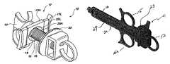
- FIG. 1is a perspective view of a syringe of the instant invention
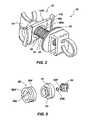
- FIG. 2is a perspective view of the proximal portion of the syringe of FIG. 1 ;
- FIG. 3is an exploded view of a syringe plunger and encasing sleeve
- FIGS. 4 and 5are exploded views of components associated with the plunger tip
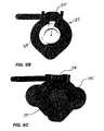
- FIGS. 6A-6Cinclude several views of a clamshell locking mechanism for a syringe of the instant invention
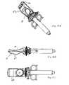
- FIG. 7is a cross-sectional perspective view of the syringe of FIG. 1 ;
- FIGS. 8A-8Care perspective views of a syringe with a streamlined block-shaped head containing the pressure display
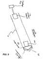
- FIG. 9is a cross-sectional view of a plunger having electronic means which transmits a wireless signal to a pressure display located at the proximal end of the plunger;
- FIG. 10is a perspective view of the syringe of FIGS. 8A-8C with fanciful display holder.
- FIG. 1is an external perspective view of a syringe 10 of the instant invention having the electronics housed in the plunger 11 , a thumb ring 12 affixed to the proximal end of the plunger 11 for control of fluid pressure syringe 10 .
- the plunger 11is enveloped at least partially by a rotatable sleeve 16 with a captivated thread mechanism 13 capable of rotating independent of the plunger end cap 19 (see FIG. 4 ), a locking mechanism housing 17 and a sliding thread locking mechanism 18 .
- the syringe barrel 14is similar to one known in the art and incorporates rings 15 and 15 a for the index finger and the middle finger.
- the triangular arrangement of the plunger thumb ring 12 and barrel rings 15 and 15 afacilitates one-handed operation of the syringe. This is a great advantage for any physician or technician performing any procedure in which fluid pressure is directly or indirectly applied to any human body part including a spinal disk or an artery. It is typically advantageous to have one free hand for accomplishing other tasks during any operation of a syringe.
- the syringe barrelhas a luer lock or a slip socket 20 for a bonded extension line.
- the locking mechanism housing 17is molded to attach to the proximal end of the syringe 10 and captivates a sliding thread locking mechanism 18 that engages or releases the threads of rotatable sleeve 16 . Sliding this mechanism to one side allows the plunger 11 to travel free in the barrel 14 , sliding to the other side locks the mechanism and requires that the thumbwheel 23 be rotated to generate minute movement of the plunger 11 and associated volume or pressure change in the syringe lumen.
- the cutout 25 in the body of the sliding thread locking mechanism 18is a keyhole-shaped opening with a minor width such that it will engage with the threads of the threaded rotatable sleeve 16 (see FIG. 3 ), and has sufficient relief in its major diameter to allow free travel of the plunger 11 when threads of the rotatable sleeve 16 are disengaged. Rapid disengagement is very desirable since many procedures may require an instantaneous release of fluid pressure to prevent or minimize some damage to a body part being treated or investigated.
- the plunger of the syringe illustrated in FIG. 3has a smooth inner bore 26 and outer bore 27 .
- the outer bore 27becomes the supporting surface for the rotation of the threaded rotatable sleeve 16 .
- displacement of the plunger 11is generated by rotation of the thumbwheel 23 which forces the distal end of the rotatable sleeve 16 against a flange, such as provided by plunger end cap 19 adjacent the distal end of the plunger 11 .
- the axial advancement or retraction of the plunger 11 effected by rotation of thumbwheel 23is very slight, thus minute adjustments of fluid pressure are readily accomplished.
- thumbwheel 23Also advantageous is the location of the thumbwheel 23 since its position vis-a-vis rings 15 and 15 a and thumb ring 12 readily permits an operator's thumb to be removed from thumb ring 12 and placed upon thumbwheel 23 to rotate thumbwheel 23 to achieve minute fluid pressure adjustments. This continuous one-handed operation of the syringe is very advantageous for a variety of reasons.
- the plunger end cap 19receives an electronic transducer, similar to those described and illustrated in the U.S. patents to Wallace, cited hereinabove, which is retained by the transducer retainer 31 .
- the friction reduction washer 30is placed on the plunger's smooth outer bore 27 after the threaded rotatable sleeve 16 slides over plunger 11 , thus acting as a friction reducing bearing between the threaded rotatable sleeve 16 and the plunger end cap 19 .
- the rubber plunger tip 32is snapped over the detent 33 of the plunger end cap 19 , as depicted in FIGS. 4 and 5 .
- the plunger tip assemblyconsists of a transducer that is seated within the plunger end cap 19 .
- the cavity of the plunger end cap 19is filled with a force transmitting silicone gel which allows the transmission of forces to the transducer.
- Other arrangements for appropriate attachment of the transducer to the plunger tipmay, of course, be utilized.
- FIGS. 6A-6CWhile a slide-lock mechanism has been illustrated and described herein, other locking mechanisms may be effectively utilized.
- a two-piece clam-shell, spring-loaded mechanismsuch as that shown in FIGS. 6A-6C can be usefully employed.
- a pair of clam-shaped elements 34 and 35are hinged at their closed end and spring-biased to be in a closed position whereby the elements 34 and 35 clamp the threaded sleeve or threaded plunger 37 .
- a rotatable cam 36is positioned at the open end of the clam-shaped elements 34 and 35 , whereby rotation of the cam 36 forces the clam-shaped elements 34 and 35 into an “open” position whereby a threaded sleeve or plunger may slide freely.
- the “open” positionis illustrated in FIG. 6A while FIGS. 6B and 6C illustrate the “closed” position.
- the transducermay also be utilized in a conventional manner, as illustrated in U.S. Pat. No. 5,004,47
- Preferred locking mechanismsare those which are operable by the same hand which is otherwise holding or operating the syringe.
- the locking mechanismcan be set or released by the thumb of the hand engaging one or more of the finger rings of the syringe.
- having a threaded sleeve engage the locking mechanismpermits minor axial adjustments of the plunger without rotation of the plunger itself which keeps a pressure readout display 39 ( FIGS. 8A-8C ) affixed at the proximal end of the plunger in a continuously visible position.
- the pressure transducer and associated electronicsare all incorporated as part of the plunger and the electronics send a wireless signal to a remote display, then the plunger itself may be threaded near its proximal end for engagement with a suitable locking mechanism to accomplish minute axial adjustment of the plunger which is caused by minor rotation of the plunger.
- a thumb ring for a thread plunger with a slightly larger open diametermay facilitate positioning of an operator's thumb even though the thumb ring may be rotated slightly. Also, a thumb ring which is fixed to a threaded plunger so the thumb ring freely rotates also accommodates plunger rotation.
- a plungerwhich incorporates a pressure transducer and associated electronics is useful with either a threaded plunger or a threaded sleeve freely encasing the plunger.
- FIG. 7is a perspective, sectional view along a longitudinal plane encompassing the central longitudinal axis.
- the finger rings 15 and 15 a and thumb ring 12are shown at the proximal end of the syringe.
- the open central cavity 37 (also depicted in FIG. 6A ) of the plungeris exposed. It is in this space that an electronics assembly may be incorporated to connect a pressure transducer in the plunger top to a pressure readout display located in the display holder located at the proximal end of the plunger.
- the plunger 11 and its threaded rotatable sleeve 16are illustrated in an inserted position in the syringe barrel.
- the thumbwheel 23 and sliding thread locking mechanismare also illustrated.
- the sleeve and plungerslide longitudinally within the syringe barrel except when the sliding thread locking mechanism engages the threads of the sleeve.
- the thumbwheel 23is fixed to the sleeve so that rotation of the thumbwheel 23 rotates the sleeve threads with respect to the sliding thread locking mechanism causing the plunger 11 to advance or withdraw depending upon the direction of rotation of the thumbwheel 23 .
- Rotation of the thumbwheel 23 while the sliding thread locking mechanism engages the threads of the sleevecauses minute longitudinal movement of the plunger, permitting minor adjustments in the fluid pressure in the barrel and attached lumen.
- Such precise adjustment of fluid pressureis very desirable for a number of medical procedures, such as discography and angioplasty procedures.
- Fluid pressure within the barrelmay be quickly decreased to zero by unlocking the slide lock and allowing the plunger to retreat.
- a further embodiment of the inventionincorporates a wireless transmission of pressure information from the pressure transducer to the readout display at the proximal end of the syringe.
- the transducer analog outputmay be introduced to a wireless transmitter to transmit an analog signal to the distal end of the syringe where a wireless receiver receives the signal, converts it to a digital signal, which is then introduced directly into the digital readout display.
- the wireless transmittermay be an infrared (IR) processor/transmitter which receives the analog electrical signal, converts it into an infrared analog signal which is emitted from an IR emitter.
- the IR analog signalis transmitted through the body of the syringe preferably through an open channel to an IR analog receiver/converter at the proximal end of the syringe.
- the electrical signalmay be converted into a digital IR or other digital wireless signal to be received by an appropriate receiver.
- An optical fibermay be advantageously used for precise IR transmission from the IR transmitter to the IR receiver.
- a digital signalmay be sent via an electrical conductor between the transducer/transmitter and the receiver/display.
- radio signalsmay interfere with various other equipment in an operating room-type of environment and would generally be contraindicated where such a syringe was to be utilized upon a patient having a pacemaker.
- FIGS. 8A-8Care perspective views of a syringe with a pressure display head located in a display holder having a thumb aperture located between the display and the plunger.
- FIG. 8Ais a perspective view of a syringe with a pressure display head located in a display holder having a thumb aperture located between the display and the plunger.
- This particular syringemay incorporate the wired connection between the pressure transducer and the pressure display or a wireless transmission system such as that illustrated in FIG. 9 .
- FIGS. 8B and 8Cshow an elevational view and plan view, respectively, of the syringe (infuser) of FIG. 8A .
- the display holding portion 47 of the syringeis unique in appearance, as can be seen in FIGS. 8A , 8 B and 8 C. Additionally, the style, shape and juxtaposition of the various elements of the syringe further provide a syringe of a distinctive appearance.
- FIG. 8Cshows the bottom of the display holding portion 47 , assuming that the surface in which the display is embedded is denoted the top surface, which is visible in FIGS. 8A and 8B .
- the syringe of FIGS. 8A , 8 B and 8 Chas the operator's thumb preferably inserted in a thumb aperture 38 from the bottom so that the display 39 will face upwards to the technician operating the syringe.
- This particular syringemay incorporate the wired connection between the pressure transducer and the pressure display or a wireless transmission system such as that illustrated in FIG. 9 , described hereinbelow.
- FIG. 9An embodiment of the invention is shown in FIG. 9 illustrating, in perspective view, a hollow plunger 11 having a pressure sensing transducer 48 located at or near the plunger tip 49 (distal end), which transducer 48 is electrically connected to an electronics system 40 which wirelessly transmits its output signal (IR or RF) to a remote receiver/pressure display 41 system.
- a display 42may be located at or near the proximal end of the plunger 11 or at a remote location separate from the plunger 11 , e.g., attached to an external surface of the syringe or entirely separate and remote from the syringe, e.g., on a support which positions the pressure display visible 42 to one or more members of a team involved in an infusion procedure.
- the signal transmitted from the electronics system 40 to the display 42may be an analog or a digital signal. If the signal is an analog signal, then the pressure display 42 includes a receiver mechanism which receives the signal and converts the analog signal to a digital signal suitable for being displayed as a pressure in millimeters of mercury, pounds per square inch, or other useful pressure units.
- the display 42may further have a memory device whereby the total infusion procedure is recorded in terms of elapsed time and regular (substantially continuously, if desired) pressure recordings so that a history of the entire infusion procedure may be later downloaded for permanent storage.
- a substantially hollow plunger having an internal pressure sensing mechanism, e.g., pressure transducer, in the tip, which is in direct or indirect contact with fluid of a syringe being pressurizedhas many advantages, many of which have been enumerated herein.
- One such advantageis that a direct pressure reading may be displayed in a display incorporated in the proximal end of the plunger.
- a fluid, preferably liquidmay be contained within the hollow plunger to contact a dynamic (diaphragm) type-pressure influenced mechanism and conduct the received pressure through the fluid, preferably liquid, to a pressure transducer/display in the proximal end of the plunger.
- the pressure experienced at the tip of the plungeris transmitted by a fluid conductor to a pressure transducer or other pressure metering means, e.g., an analog pressure meter, at the proximal end of the plunger.
- a pressure transducer or other pressure metering meanse.g., an analog pressure meter
- Such a structurepermits all the electronics necessary for a digital display, e.g., pressure transducer, analog/digital converter and digital signal receiving display to be directly coupled to one another and located at or near the proximal end of the hollow plunger.
- the display at the proximal end of the syringemay be incorporated into a housing of the varying shapes and designs shown herein which accommodate functional purposes.
- the shape of the display housing shown in FIGS. 8A-8Cis particularly fanciful to provide a smooth aesthetic appearance while not diminishing its attributes as a display holder and thumb engagement device.
- FIG. 10A further perspective view of the syringe of FIGS. 8A-8C is shown in FIG. 10 . The view is at an oblique angle from the rear of the syringe.
Landscapes
- Health & Medical Sciences (AREA)
- Life Sciences & Earth Sciences (AREA)
- Heart & Thoracic Surgery (AREA)
- Engineering & Computer Science (AREA)
- Biophysics (AREA)
- Pulmonology (AREA)
- Child & Adolescent Psychology (AREA)
- Anesthesiology (AREA)
- Biomedical Technology (AREA)
- Hematology (AREA)
- Animal Behavior & Ethology (AREA)
- General Health & Medical Sciences (AREA)
- Public Health (AREA)
- Veterinary Medicine (AREA)
- Infusion, Injection, And Reservoir Apparatuses (AREA)
Abstract
Description
Claims (14)
Priority Applications (2)
| Application Number | Priority Date | Filing Date | Title |
|---|---|---|---|
| US10/769,634US7351223B2 (en) | 2003-05-05 | 2004-01-30 | Infusion syringe with integrated pressure transducer |
| US10/831,769US7291131B2 (en) | 2003-05-05 | 2004-04-23 | Infusion syringe |
Applications Claiming Priority (2)
| Application Number | Priority Date | Filing Date | Title |
|---|---|---|---|
| US46839803P | 2003-05-05 | 2003-05-05 | |
| US10/769,634US7351223B2 (en) | 2003-05-05 | 2004-01-30 | Infusion syringe with integrated pressure transducer |
Related Child Applications (2)
| Application Number | Title | Priority Date | Filing Date |
|---|---|---|---|
| US10/831,769Continuation-In-PartUS7291131B2 (en) | 2003-05-05 | 2004-04-23 | Infusion syringe |
| US29/269,669Continuation-In-PartUSD562447S1 (en) | 2004-01-30 | 2006-12-06 | Portion of a syringe |
Publications (2)
| Publication Number | Publication Date |
|---|---|
| US20040260238A1 US20040260238A1 (en) | 2004-12-23 |
| US7351223B2true US7351223B2 (en) | 2008-04-01 |
Family
ID=33519187
Family Applications (1)
| Application Number | Title | Priority Date | Filing Date |
|---|---|---|---|
| US10/769,634Expired - LifetimeUS7351223B2 (en) | 2003-05-05 | 2004-01-30 | Infusion syringe with integrated pressure transducer |
Country Status (1)
| Country | Link |
|---|---|
| US (1) | US7351223B2 (en) |
Cited By (29)
| Publication number | Priority date | Publication date | Assignee | Title |
|---|---|---|---|---|
| US20070129708A1 (en)* | 2005-02-01 | 2007-06-07 | Edwards Eric S | Devices, systems and methods for medicament delivery |
| US20080033393A1 (en)* | 2005-02-01 | 2008-02-07 | Edwards Eric S | Devices, systems and methods for medicament delivery |
| US20090024112A1 (en)* | 2005-02-01 | 2009-01-22 | Edwards Eric S | Medical injector with compliance tracking and monitoring |
| US20100094229A1 (en)* | 2003-02-21 | 2010-04-15 | Smith & Nephew, Inc. | Spinal fluid introduction |
| US20100174162A1 (en)* | 2002-11-25 | 2010-07-08 | Boston Scientific Scimed, Inc. | Injection device |
| US20100179488A1 (en)* | 2009-01-15 | 2010-07-15 | Spiegel Joan E | Pressure measuring syringe |
| US8206360B2 (en) | 2005-02-01 | 2012-06-26 | Intelliject, Inc. | Devices, systems and methods for medicament delivery |
| US8231573B2 (en) | 2005-02-01 | 2012-07-31 | Intelliject, Inc. | Medicament delivery device having an electronic circuit system |
| US8361026B2 (en) | 2005-02-01 | 2013-01-29 | Intelliject, Inc. | Apparatus and methods for self-administration of vaccines and other medicaments |
| USD710496S1 (en)* | 2011-10-27 | 2014-08-05 | Merit Medical Systems, Inc. | Mechanically assisted device handle |
| US8932252B2 (en) | 2005-02-01 | 2015-01-13 | Kaleo, Inc. | Medical injector simulation device |
| USD726311S1 (en)* | 2012-06-13 | 2015-04-07 | Fred Lampropoulos | Mechanically assisted device handle |
| USD754685S1 (en) | 2014-08-01 | 2016-04-26 | Merit Medical Systems, Inc. | Display screen with graphical user interface |
| USD759079S1 (en) | 2014-08-01 | 2016-06-14 | Merit Medical Systems, Inc. | Inflation device display screen with graphical user interface |
| USD767126S1 (en) | 2014-10-10 | 2016-09-20 | Merit Medical Systems, Inc. | Inflation device module |
| US9522235B2 (en) | 2012-05-22 | 2016-12-20 | Kaleo, Inc. | Devices and methods for delivering medicaments from a multi-chamber container |
| US9542826B2 (en) | 2012-12-27 | 2017-01-10 | Kaleo, Inc. | Devices, systems and methods for locating and interacting with medicament delivery systems |
| US9987471B2 (en) | 2011-05-06 | 2018-06-05 | Merit Medical Systems, Inc. | Mechanically assisted inflation device handle and method of use |
| US10033027B2 (en) | 2015-03-04 | 2018-07-24 | Merit Medical Systems, Inc. | Pull tab assemblies for transitionally interrupting an electrical connection with a battery |
| US10046144B2 (en) | 2013-08-03 | 2018-08-14 | Merit Medical Systems, Inc. | Methods of resetting inflation devices |
| US10183116B2 (en) | 2011-01-26 | 2019-01-22 | Kaleo, Inc. | Devices and methods for delivering medicaments from a multi-chamber container |
| US10332623B2 (en) | 2017-01-17 | 2019-06-25 | Kaleo, Inc. | Medicament delivery devices with wireless connectivity and event detection |
| US10398881B2 (en) | 2013-08-03 | 2019-09-03 | Merit Medical Systems, Inc. | Inflation devices with remote displays, methods and kits related thereto |
| USD876622S1 (en)* | 2016-09-19 | 2020-02-25 | Merit Medical Systems, Inc. | High pressure mechanically assisted device handle |
| US10695495B2 (en) | 2015-03-24 | 2020-06-30 | Kaleo, Inc. | Devices and methods for delivering a lyophilized medicament |
| US11413397B2 (en) | 2016-12-16 | 2022-08-16 | The Brigham And Women's Hospital, Inc. | System and method for resistance-dependent, self-regulated medical penetration |
| US11439796B2 (en) | 2018-04-26 | 2022-09-13 | Merit Medical Systems, Inc. | Inflation devices with proximity pairing and methods and systems related thereto |
| USD994111S1 (en) | 2008-05-12 | 2023-08-01 | Kaleo, Inc. | Medicament delivery device cover |
| US11929160B2 (en) | 2018-07-16 | 2024-03-12 | Kaleo, Inc. | Medicament delivery devices with wireless connectivity and compliance detection |
Families Citing this family (23)
| Publication number | Priority date | Publication date | Assignee | Title |
|---|---|---|---|---|
| US7998213B2 (en) | 1999-08-18 | 2011-08-16 | Intrinsic Therapeutics, Inc. | Intervertebral disc herniation repair |
| CA2425951C (en) | 1999-08-18 | 2008-09-16 | Intrinsic Therapeutics, Inc. | Devices and method for nucleus pulposus augmentation and retention |
| US7972337B2 (en) | 2005-12-28 | 2011-07-05 | Intrinsic Therapeutics, Inc. | Devices and methods for bone anchoring |
| US8323341B2 (en) | 2007-09-07 | 2012-12-04 | Intrinsic Therapeutics, Inc. | Impaction grafting for vertebral fusion |
| US20040010317A1 (en)* | 1999-08-18 | 2004-01-15 | Gregory Lambrecht | Devices and method for augmenting a vertebral disc |
| US7717961B2 (en) | 1999-08-18 | 2010-05-18 | Intrinsic Therapeutics, Inc. | Apparatus delivery in an intervertebral disc |
| US7094258B2 (en) | 1999-08-18 | 2006-08-22 | Intrinsic Therapeutics, Inc. | Methods of reinforcing an annulus fibrosis |
| EP1624832A4 (en) | 1999-08-18 | 2008-12-24 | Intrinsic Therapeutics Inc | Devices and method for augmenting a vertebral disc nucleus |
| US7553329B2 (en) | 1999-08-18 | 2009-06-30 | Intrinsic Therapeutics, Inc. | Stabilized intervertebral disc barrier |
| JP2007515988A (en) | 2003-06-20 | 2007-06-21 | イントリンジック セラピューティックス インコーポレイテッド | Device and method for delivering an implant from an annular defect of an intervertebral disc |
| US20040260300A1 (en) | 2003-06-20 | 2004-12-23 | Bogomir Gorensek | Method of delivering an implant through an annular defect in an intervertebral disc |
| USD579561S1 (en)* | 2004-01-30 | 2008-10-28 | Physician Industries, Inc. | Portion of a syringe |
| US8029511B2 (en)* | 2004-03-22 | 2011-10-04 | Disc Dynamics, Inc. | Multi-stage biomaterial injection system for spinal implants |
| WO2006130491A2 (en) | 2005-05-27 | 2006-12-07 | Stryker Corporation | Hand-held fluid delivery device with sensors to determine fluid pressure and volume of fluid delivered to intervertebral discs during discography |
| CN101438327B (en)* | 2006-03-29 | 2013-11-06 | 因特利杰克特有限公司 | Devices, systems and methods for medicament delivery |
| WO2007126851A2 (en)* | 2006-03-29 | 2007-11-08 | Intelliject, Llc | Devices, systems and methods for medicament delivery |
| US20110196492A1 (en) | 2007-09-07 | 2011-08-11 | Intrinsic Therapeutics, Inc. | Bone anchoring systems |
| US8191457B2 (en)* | 2008-11-13 | 2012-06-05 | Atrion Medical Products, Inc. | Actuating mechanism for fluid displacement and pressurizing device |
| US8499681B2 (en) | 2008-11-13 | 2013-08-06 | Atrion Medical Products, Inc. | Actuating mechanism for fluid displacement and pressurizing device |
| CN103874522B (en)* | 2011-10-11 | 2016-02-03 | 呼吸医疗技术有限公司 | Pressure regulates syringe and method thereof |
| CN104968380B (en)* | 2013-01-29 | 2018-08-21 | 赛诺菲-安万特德国有限公司 | Assemblies for detecting plunger position |
| GB2568061A (en)* | 2017-11-02 | 2019-05-08 | Biocompatibles Uk Ltd | Apparatus for delivering a composition for a vascular embolisation |
| CH714883A1 (en)* | 2018-04-12 | 2019-10-15 | Medicel Ag | Injector with two operating modes, in particular suitable for injecting an intraocular lens. |
Citations (70)
| Publication number | Priority date | Publication date | Assignee | Title |
|---|---|---|---|---|
| US3625793A (en) | 1969-09-23 | 1971-12-07 | David S Sheridan | Balloon-type catheters and method of manufacture |
| US3878830A (en) | 1973-05-31 | 1975-04-22 | Mediscience Technology Corp | Catheter system for blood gas monitoring |
| USRE30365E (en) | 1971-05-03 | 1980-08-12 | Disposable catheter | |
| US4370982A (en) | 1980-09-10 | 1983-02-01 | Medrad, Inc. | Method and apparatus for injecting and for controlling the pressure of fluid being injected into a catheter |
| US4439185A (en) | 1981-10-21 | 1984-03-27 | Advanced Cardiovascular Systems, Inc. | Inflating and deflating device for vascular dilating catheter assembly |
| US4583974A (en)* | 1984-04-04 | 1986-04-22 | Kokernak Denis T | Syringe for balloon dilation catheters |
| US4651738A (en) | 1985-08-02 | 1987-03-24 | Baylor College Of Medicine | Method and device for performing transluminal angioplasty |
| US4655749A (en)* | 1985-09-30 | 1987-04-07 | Fischione Eugene A | Angioplasty pressure controller |
| US4710179A (en) | 1986-10-27 | 1987-12-01 | Habley Medical Technology Corporation | Snap-on vernier syringe |
| US4723938A (en) | 1986-12-24 | 1988-02-09 | Schneider-Shiley (Usa) Inc. | Single plunger inflation device for angioplasty catheter |
| US4740203A (en) | 1986-06-05 | 1988-04-26 | Thomas J. Fogarty | Refillable injection device |
| US4758223A (en) | 1986-07-02 | 1988-07-19 | Schneider-Shiley (Usa) Inc. | Inflation device for angioplasty catheter |
| US4810249A (en) | 1987-03-12 | 1989-03-07 | Habley Medical Technology Corp. | Linear and Vernier-type syringe |
| US4815313A (en)* | 1987-11-16 | 1989-03-28 | Abbott Laboratories | Syringe pressure calibration reference |
| US4832692A (en) | 1986-10-14 | 1989-05-23 | Cordis Corporation | Inflation syringe assembly for percutaneous transluminal angioplasty |
| US4873986A (en)* | 1987-04-01 | 1989-10-17 | Utah Medical Products | Disposable apparatus for monitoring intrauterine pressure and fetal heart rate |
| US4919121A (en) | 1989-02-06 | 1990-04-24 | Schneider (Usa) Inc., A Pfizer Company | Inflation device for angioplasty catheter |
| US4940459A (en) | 1988-10-12 | 1990-07-10 | Mallinckrodt, Inc. | Inflation device for balloon catheter |
| US4951677A (en) | 1988-03-21 | 1990-08-28 | Prutech Research And Development Partnership Ii | Acoustic imaging catheter and the like |
| US5004472A (en) | 1988-08-10 | 1991-04-02 | Wallace William D | Medical pressure sensing and display system |
| US5019041A (en) | 1988-03-08 | 1991-05-28 | Scimed Life Systems, Inc. | Balloon catheter inflation device |
| US5047015A (en) | 1989-03-17 | 1991-09-10 | Merit Medical Systems, Inc. | Locking syringe |
| US5057078A (en)* | 1989-03-17 | 1991-10-15 | Merit Medical Systems, Inc. | Locking syringe |
| US5084060A (en) | 1989-02-15 | 1992-01-28 | Freund Precision, Inc. | Apparatus for enlarging a vessel or clearing obstructive tissue from a vessel according to vessel compliance |
| US5137514A (en) | 1990-11-01 | 1992-08-11 | Accumed Systems, Inc. | Inflation syringe assembly for percutaneous transluminal angioplasty |
| US5168757A (en) | 1990-05-15 | 1992-12-08 | Ryder International Corporation | Fluid displacement and pressurizing device |
| US5201753A (en) | 1989-03-17 | 1993-04-13 | Merit Medical Systems, Inc. | Totally self-contained, digitally controlled, disposable syringe inflation system, and method for monitoring, displaying and recording balloon catheter inflation data |
| US5209732A (en) | 1989-03-17 | 1993-05-11 | Merit Medical Systems, Inc. | Locking syringe with thread-release lock |
| US5213115A (en)* | 1990-10-23 | 1993-05-25 | Burron Cardiovascular, A Division Of B. Braun Medical, Inc. | Inflation system for a balloon catheter |
| US5215523A (en) | 1991-05-30 | 1993-06-01 | Eli Williams | Balloon catheter inflation syringe with remote display |
| US5232024A (en) | 1991-05-30 | 1993-08-03 | Eli Williams | Slide-valve manifold |
| US5246011A (en)* | 1992-01-30 | 1993-09-21 | Caillouette James C | Fine needle aspiration syringe |
| US5273537A (en) | 1992-03-06 | 1993-12-28 | Scimed Life Systems, Inc. | Power-assisted inflation apparatus |
| US5318534A (en) | 1993-03-12 | 1994-06-07 | Professional Medical, Inc. | Syringe for balloon catheterization |
| US5383855A (en) | 1992-08-20 | 1995-01-24 | Medex, Inc. | Electronically monitored angioplasty system |
| US5387194A (en)* | 1991-11-12 | 1995-02-07 | Surgical Technologies, Inc. | Remote display of patient monitored data |
| US5403274A (en) | 1993-03-15 | 1995-04-04 | Cannon; Louis A. | Perfusion catheter and method of use |
| US5425713A (en) | 1989-03-17 | 1995-06-20 | Merit Medical Systems, Inc. | System and method for monitoring, displaying and recording balloon catheter condition interval and inflation location data |
| US5431629A (en) | 1989-03-17 | 1995-07-11 | Merit Medical Systems, Inc. | System and method for monitoring, displaying and recording balloon catheter condition interval data |
| US5449344A (en) | 1992-06-18 | 1995-09-12 | Merit Medical Systems, Inc. | Syringe apparatus with pressure gauge and detachable timer |
| US5449345A (en)* | 1989-03-17 | 1995-09-12 | Merit Medical Systems, Inc. | Detachable and reusable digital control unit for monitoring balloon catheter data in a syringe inflation system |
| US5453091A (en) | 1989-03-17 | 1995-09-26 | Merit Medical Systems, Inc. | RF transmission module for wirelessly transmitting balloon catheter data in a syringe inflation system |
| US5458571A (en) | 1989-03-17 | 1995-10-17 | Merit Medical Systems, Inc. | System and method for monitoring, displaying and recording balloon catheter condition interval data |
| US5459700A (en) | 1993-11-22 | 1995-10-17 | Advanced Cardiovascular Systems, Inc. | Manual timer control for inflation device |
| US5460609A (en) | 1993-11-22 | 1995-10-24 | Advanced Cardiovascular Systems, Inc. | Electromechanical inflation/deflation system |
| US5472424A (en) | 1994-04-05 | 1995-12-05 | Merit Medical Systems, Inc. | Syringe with volume displacement apparatus |
| US5489256A (en) | 1992-09-01 | 1996-02-06 | Adair; Edwin L. | Sterilizable endoscope with separable disposable tube assembly |
| US5545133A (en) | 1994-09-16 | 1996-08-13 | Scimed Life Systems, Inc. | Balloon catheter with improved pressure source |
| US5562614A (en) | 1993-11-22 | 1996-10-08 | Advanced Cardiovascular Systems, Inc. | Programmable manifold system for automatic fluid delivery |
| US5599301A (en) | 1993-11-22 | 1997-02-04 | Advanced Cardiovascular Systems, Inc. | Motor control system for an automatic catheter inflation system |
| US5625144A (en) | 1994-02-08 | 1997-04-29 | Chang; Yih-Min | Simple, low-cost, low-noise, and energy-efficient digital tire gauge |
| US5647847A (en) | 1994-09-16 | 1997-07-15 | Scimed Life Systems, Inc. | Balloon catheter with improved pressure source |
| US5695468A (en) | 1994-09-16 | 1997-12-09 | Scimed Life Systems, Inc. | Balloon catheter with improved pressure source |
| US5704913A (en) | 1993-02-16 | 1998-01-06 | Boston Scientific Corporation | Dilation catheter and method of treatment therewith |
| US5749853A (en) | 1995-03-17 | 1998-05-12 | Advanced Cardiovascular Systems, Inc. | Inflation control system with elapsed time measurement |
| US5785685A (en) | 1994-09-16 | 1998-07-28 | Scimed Life Systems, Inc. | Balloon catheter with improved pressure source |
| US5808203A (en)* | 1997-05-12 | 1998-09-15 | Medrad, Inc. | Fluid pressure measurement devices |
| US5860955A (en) | 1996-07-18 | 1999-01-19 | B. Braun Medical Inc. | Locking angioplasty syringe |
| US5891089A (en) | 1994-05-17 | 1999-04-06 | Hadasit Medical Research Services & Development | System and method for coronary angioplasty |
| US5951517A (en) | 1997-10-14 | 1999-09-14 | Merit Medical Systems, Inc. | One-hand pulse pump |
| US5968017A (en) | 1997-10-14 | 1999-10-19 | Merit Medical Systems, Inc. | Pulse fluid infusion systems |
| US6139523A (en) | 1999-02-01 | 2000-10-31 | Merit Medical Systems, Inc. | Isolation system for pressure gauges for permitting repeated use without sterilization |
| US6179815B1 (en) | 1998-07-21 | 2001-01-30 | Merit Medical Systems, Inc. | Low compliance inflation/deflation system |
| US6190354B1 (en) | 1994-09-16 | 2001-02-20 | Scimed Life Systems, Inc. | Balloon catheter with improved pressure source |
| US6224561B1 (en)* | 1997-09-26 | 2001-05-01 | Edwards Lifesciences Corporation | Closed one-handed blood sampling system |
| US6245043B1 (en) | 1997-12-03 | 2001-06-12 | Alain Villette | Injector for medical use |
| US6394977B1 (en) | 1998-03-25 | 2002-05-28 | Merit Medical Systems, Inc. | Pressure gauge with digital stepping motor and reusable transfer plug |
| US20030216692A1 (en) | 2002-05-15 | 2003-11-20 | Liebel-Flarsheim Company | Hydraulic remote for a medical fluid injector |
| US20040024361A1 (en) | 2002-08-02 | 2004-02-05 | Mallinckrodt Inc. | Injector |
| US6792306B2 (en) | 2000-03-10 | 2004-09-14 | Biophoretic Therapeutic Systems, Llc | Finger-mounted electrokinetic delivery system for self-administration of medicaments and methods therefor |
- 2004
- 2004-01-30USUS10/769,634patent/US7351223B2/ennot_activeExpired - Lifetime
Patent Citations (83)
| Publication number | Priority date | Publication date | Assignee | Title |
|---|---|---|---|---|
| US3625793A (en) | 1969-09-23 | 1971-12-07 | David S Sheridan | Balloon-type catheters and method of manufacture |
| USRE30365E (en) | 1971-05-03 | 1980-08-12 | Disposable catheter | |
| US3878830A (en) | 1973-05-31 | 1975-04-22 | Mediscience Technology Corp | Catheter system for blood gas monitoring |
| US4370982A (en) | 1980-09-10 | 1983-02-01 | Medrad, Inc. | Method and apparatus for injecting and for controlling the pressure of fluid being injected into a catheter |
| US4439185A (en) | 1981-10-21 | 1984-03-27 | Advanced Cardiovascular Systems, Inc. | Inflating and deflating device for vascular dilating catheter assembly |
| US4583974A (en)* | 1984-04-04 | 1986-04-22 | Kokernak Denis T | Syringe for balloon dilation catheters |
| US4651738A (en) | 1985-08-02 | 1987-03-24 | Baylor College Of Medicine | Method and device for performing transluminal angioplasty |
| US4655749A (en)* | 1985-09-30 | 1987-04-07 | Fischione Eugene A | Angioplasty pressure controller |
| US4740203A (en) | 1986-06-05 | 1988-04-26 | Thomas J. Fogarty | Refillable injection device |
| US4758223A (en) | 1986-07-02 | 1988-07-19 | Schneider-Shiley (Usa) Inc. | Inflation device for angioplasty catheter |
| US4832692A (en) | 1986-10-14 | 1989-05-23 | Cordis Corporation | Inflation syringe assembly for percutaneous transluminal angioplasty |
| US4710179A (en) | 1986-10-27 | 1987-12-01 | Habley Medical Technology Corporation | Snap-on vernier syringe |
| US4723938A (en) | 1986-12-24 | 1988-02-09 | Schneider-Shiley (Usa) Inc. | Single plunger inflation device for angioplasty catheter |
| US4810249A (en) | 1987-03-12 | 1989-03-07 | Habley Medical Technology Corp. | Linear and Vernier-type syringe |
| US4873986A (en)* | 1987-04-01 | 1989-10-17 | Utah Medical Products | Disposable apparatus for monitoring intrauterine pressure and fetal heart rate |
| US4815313A (en)* | 1987-11-16 | 1989-03-28 | Abbott Laboratories | Syringe pressure calibration reference |
| US5741229A (en) | 1988-03-08 | 1998-04-21 | Scimed Life Systems, Inc. | Balloon catheter inflation device |
| US5685848A (en) | 1988-03-08 | 1997-11-11 | Scimed Life Systems, Inc. | Balloon catheter inflation device |
| US5429606A (en) | 1988-03-08 | 1995-07-04 | Scimed Life Systems, Inc. | Balloon catheter inflation device |
| US5147300A (en) | 1988-03-08 | 1992-09-15 | Scimed Life Systems, Inc. | Balloon catheter inflation device |
| US5147300B1 (en) | 1988-03-08 | 1994-04-05 | Scimed Life Systems Inc | Balloon catheter inflation device |
| US5019041A (en) | 1988-03-08 | 1991-05-28 | Scimed Life Systems, Inc. | Balloon catheter inflation device |
| US5752935A (en) | 1988-03-08 | 1998-05-19 | Scimed Life Systems, Inc. | Balloon catheter inflation device |
| US4951677A (en) | 1988-03-21 | 1990-08-28 | Prutech Research And Development Partnership Ii | Acoustic imaging catheter and the like |
| US5021046A (en) | 1988-08-10 | 1991-06-04 | Utah Medical Products, Inc. | Medical pressure sensing and display system |
| US5009662A (en) | 1988-08-10 | 1991-04-23 | Wallace William D | Medical pressure sensing and display system |
| US5004472A (en) | 1988-08-10 | 1991-04-02 | Wallace William D | Medical pressure sensing and display system |
| US5004472B1 (en) | 1988-08-10 | 1995-02-28 | Utah Medical Products Inc | Medical pressure sensing and display system |
| US5009662B1 (en) | 1988-08-10 | 1995-02-14 | Utah Medical Products | Medical pressure sensing and display system |
| US4940459A (en) | 1988-10-12 | 1990-07-10 | Mallinckrodt, Inc. | Inflation device for balloon catheter |
| US4919121A (en) | 1989-02-06 | 1990-04-24 | Schneider (Usa) Inc., A Pfizer Company | Inflation device for angioplasty catheter |
| US5084060A (en) | 1989-02-15 | 1992-01-28 | Freund Precision, Inc. | Apparatus for enlarging a vessel or clearing obstructive tissue from a vessel according to vessel compliance |
| US5385549A (en) | 1989-03-17 | 1995-01-31 | Merit Medical Systems, Inc. | Digitally controlled, disposable syringe inflation system, and method for monitoring, displaying balloon catheter inflation data |
| US5201753A (en) | 1989-03-17 | 1993-04-13 | Merit Medical Systems, Inc. | Totally self-contained, digitally controlled, disposable syringe inflation system, and method for monitoring, displaying and recording balloon catheter inflation data |
| US5057078A (en)* | 1989-03-17 | 1991-10-15 | Merit Medical Systems, Inc. | Locking syringe |
| US5047015A (en) | 1989-03-17 | 1991-09-10 | Merit Medical Systems, Inc. | Locking syringe |
| US5458571A (en) | 1989-03-17 | 1995-10-17 | Merit Medical Systems, Inc. | System and method for monitoring, displaying and recording balloon catheter condition interval data |
| US5453091A (en) | 1989-03-17 | 1995-09-26 | Merit Medical Systems, Inc. | RF transmission module for wirelessly transmitting balloon catheter data in a syringe inflation system |
| US5449345A (en)* | 1989-03-17 | 1995-09-12 | Merit Medical Systems, Inc. | Detachable and reusable digital control unit for monitoring balloon catheter data in a syringe inflation system |
| US5431629A (en) | 1989-03-17 | 1995-07-11 | Merit Medical Systems, Inc. | System and method for monitoring, displaying and recording balloon catheter condition interval data |
| US5425713A (en) | 1989-03-17 | 1995-06-20 | Merit Medical Systems, Inc. | System and method for monitoring, displaying and recording balloon catheter condition interval and inflation location data |
| US5209732A (en) | 1989-03-17 | 1993-05-11 | Merit Medical Systems, Inc. | Locking syringe with thread-release lock |
| US5168757A (en) | 1990-05-15 | 1992-12-08 | Ryder International Corporation | Fluid displacement and pressurizing device |
| US5213115A (en)* | 1990-10-23 | 1993-05-25 | Burron Cardiovascular, A Division Of B. Braun Medical, Inc. | Inflation system for a balloon catheter |
| US5137514A (en) | 1990-11-01 | 1992-08-11 | Accumed Systems, Inc. | Inflation syringe assembly for percutaneous transluminal angioplasty |
| US5215523A (en) | 1991-05-30 | 1993-06-01 | Eli Williams | Balloon catheter inflation syringe with remote display |
| US5232024A (en) | 1991-05-30 | 1993-08-03 | Eli Williams | Slide-valve manifold |
| US5387194A (en)* | 1991-11-12 | 1995-02-07 | Surgical Technologies, Inc. | Remote display of patient monitored data |
| US5246011A (en)* | 1992-01-30 | 1993-09-21 | Caillouette James C | Fine needle aspiration syringe |
| US5273537A (en) | 1992-03-06 | 1993-12-28 | Scimed Life Systems, Inc. | Power-assisted inflation apparatus |
| US5449344A (en) | 1992-06-18 | 1995-09-12 | Merit Medical Systems, Inc. | Syringe apparatus with pressure gauge and detachable timer |
| US5383855A (en) | 1992-08-20 | 1995-01-24 | Medex, Inc. | Electronically monitored angioplasty system |
| US5489256A (en) | 1992-09-01 | 1996-02-06 | Adair; Edwin L. | Sterilizable endoscope with separable disposable tube assembly |
| US5704913A (en) | 1993-02-16 | 1998-01-06 | Boston Scientific Corporation | Dilation catheter and method of treatment therewith |
| US5318534A (en) | 1993-03-12 | 1994-06-07 | Professional Medical, Inc. | Syringe for balloon catheterization |
| US5433707A (en) | 1993-03-12 | 1995-07-18 | Surgical Technologies, Inc. | Syringe for balloon catheterization |
| US5403274A (en) | 1993-03-15 | 1995-04-04 | Cannon; Louis A. | Perfusion catheter and method of use |
| US5599301A (en) | 1993-11-22 | 1997-02-04 | Advanced Cardiovascular Systems, Inc. | Motor control system for an automatic catheter inflation system |
| US5460609A (en) | 1993-11-22 | 1995-10-24 | Advanced Cardiovascular Systems, Inc. | Electromechanical inflation/deflation system |
| US5562614A (en) | 1993-11-22 | 1996-10-08 | Advanced Cardiovascular Systems, Inc. | Programmable manifold system for automatic fluid delivery |
| US5459700A (en) | 1993-11-22 | 1995-10-17 | Advanced Cardiovascular Systems, Inc. | Manual timer control for inflation device |
| US5625144A (en) | 1994-02-08 | 1997-04-29 | Chang; Yih-Min | Simple, low-cost, low-noise, and energy-efficient digital tire gauge |
| US5472424A (en) | 1994-04-05 | 1995-12-05 | Merit Medical Systems, Inc. | Syringe with volume displacement apparatus |
| US5891089A (en) | 1994-05-17 | 1999-04-06 | Hadasit Medical Research Services & Development | System and method for coronary angioplasty |
| US6190354B1 (en) | 1994-09-16 | 2001-02-20 | Scimed Life Systems, Inc. | Balloon catheter with improved pressure source |
| US5647847A (en) | 1994-09-16 | 1997-07-15 | Scimed Life Systems, Inc. | Balloon catheter with improved pressure source |
| US5695468A (en) | 1994-09-16 | 1997-12-09 | Scimed Life Systems, Inc. | Balloon catheter with improved pressure source |
| US5785685A (en) | 1994-09-16 | 1998-07-28 | Scimed Life Systems, Inc. | Balloon catheter with improved pressure source |
| US5545133A (en) | 1994-09-16 | 1996-08-13 | Scimed Life Systems, Inc. | Balloon catheter with improved pressure source |
| US5728064A (en) | 1994-09-16 | 1998-03-17 | Scimed Life Systems, Inc. | Balloon catheter with improved pressure source |
| US5749853A (en) | 1995-03-17 | 1998-05-12 | Advanced Cardiovascular Systems, Inc. | Inflation control system with elapsed time measurement |
| US5860955A (en) | 1996-07-18 | 1999-01-19 | B. Braun Medical Inc. | Locking angioplasty syringe |
| US5808203A (en)* | 1997-05-12 | 1998-09-15 | Medrad, Inc. | Fluid pressure measurement devices |
| US6224561B1 (en)* | 1997-09-26 | 2001-05-01 | Edwards Lifesciences Corporation | Closed one-handed blood sampling system |
| US5968017A (en) | 1997-10-14 | 1999-10-19 | Merit Medical Systems, Inc. | Pulse fluid infusion systems |
| US5951517A (en) | 1997-10-14 | 1999-09-14 | Merit Medical Systems, Inc. | One-hand pulse pump |
| US6245043B1 (en) | 1997-12-03 | 2001-06-12 | Alain Villette | Injector for medical use |
| US6394977B1 (en) | 1998-03-25 | 2002-05-28 | Merit Medical Systems, Inc. | Pressure gauge with digital stepping motor and reusable transfer plug |
| US6179815B1 (en) | 1998-07-21 | 2001-01-30 | Merit Medical Systems, Inc. | Low compliance inflation/deflation system |
| US6139523A (en) | 1999-02-01 | 2000-10-31 | Merit Medical Systems, Inc. | Isolation system for pressure gauges for permitting repeated use without sterilization |
| US6792306B2 (en) | 2000-03-10 | 2004-09-14 | Biophoretic Therapeutic Systems, Llc | Finger-mounted electrokinetic delivery system for self-administration of medicaments and methods therefor |
| US20030216692A1 (en) | 2002-05-15 | 2003-11-20 | Liebel-Flarsheim Company | Hydraulic remote for a medical fluid injector |
| US20040024361A1 (en) | 2002-08-02 | 2004-02-05 | Mallinckrodt Inc. | Injector |
Cited By (71)
| Publication number | Priority date | Publication date | Assignee | Title |
|---|---|---|---|---|
| US8545478B2 (en) | 2002-11-25 | 2013-10-01 | Boston Scientific Scimed, Inc. | Injection device |
| US20100174162A1 (en)* | 2002-11-25 | 2010-07-08 | Boston Scientific Scimed, Inc. | Injection device |
| US20100094229A1 (en)* | 2003-02-21 | 2010-04-15 | Smith & Nephew, Inc. | Spinal fluid introduction |
| US8920367B2 (en) | 2005-02-01 | 2014-12-30 | Kaleo, Inc. | Devices, systems and methods for medicament delivery |
| US10099023B2 (en) | 2005-02-01 | 2018-10-16 | Kaleo, Inc. | Devices, systems and methods for medicament delivery |
| US7731686B2 (en) | 2005-02-01 | 2010-06-08 | Intelliject, Inc. | Devices, systems and methods for medicament delivery |
| US7749194B2 (en) | 2005-02-01 | 2010-07-06 | Intelliject, Inc. | Devices, systems, and methods for medicament delivery |
| US20080103490A1 (en)* | 2005-02-01 | 2008-05-01 | Eric Shawn Edwards | Devices, systems and methods for medicament delivery |
| US10076611B2 (en) | 2005-02-01 | 2018-09-18 | Kaleo, Inc. | Medicament delivery device having an electronic circuit system |
| US8123719B2 (en) | 2005-02-01 | 2012-02-28 | Intelliject, Inc. | Devices, systems and methods for medicament delivery |
| US8172082B2 (en) | 2005-02-01 | 2012-05-08 | Intelliject, Inc. | Devices, systems and methods for medicament delivery |
| US8206360B2 (en) | 2005-02-01 | 2012-06-26 | Intelliject, Inc. | Devices, systems and methods for medicament delivery |
| US8226610B2 (en) | 2005-02-01 | 2012-07-24 | Intelliject, Inc. | Medical injector with compliance tracking and monitoring |
| US8231573B2 (en) | 2005-02-01 | 2012-07-31 | Intelliject, Inc. | Medicament delivery device having an electronic circuit system |
| US8926594B2 (en) | 2005-02-01 | 2015-01-06 | Kaleo, Inc. | Devices, systems and methods for medicament delivery |
| US8361026B2 (en) | 2005-02-01 | 2013-01-29 | Intelliject, Inc. | Apparatus and methods for self-administration of vaccines and other medicaments |
| US20080033393A1 (en)* | 2005-02-01 | 2008-02-07 | Edwards Eric S | Devices, systems and methods for medicament delivery |
| US8544645B2 (en) | 2005-02-01 | 2013-10-01 | Intelliject, Inc. | Devices, systems and methods for medicament delivery |
| US8690827B2 (en) | 2005-02-01 | 2014-04-08 | Kaleo, Inc. | Devices, systems, and methods for medicament delivery |
| US10105489B2 (en) | 2005-02-01 | 2018-10-23 | Kaleo, Inc. | Medical injector with compliance tracking and monitoring |
| US20070129708A1 (en)* | 2005-02-01 | 2007-06-07 | Edwards Eric S | Devices, systems and methods for medicament delivery |
| US8899987B2 (en) | 2005-02-01 | 2014-12-02 | Kaleo, Inc. | Simulated medicament delivery device having an electronic circuit system |
| US9805620B2 (en) | 2005-02-01 | 2017-10-31 | Kaleo, Inc. | Medical injector simulation device |
| US9724471B2 (en) | 2005-02-01 | 2017-08-08 | Kaleo, Inc. | Devices, systems, and methods for medicament delivery |
| US20090024112A1 (en)* | 2005-02-01 | 2009-01-22 | Edwards Eric S | Medical injector with compliance tracking and monitoring |
| US8932252B2 (en) | 2005-02-01 | 2015-01-13 | Kaleo, Inc. | Medical injector simulation device |
| US9022980B2 (en) | 2005-02-01 | 2015-05-05 | Kaleo, Inc. | Medical injector simulation device |
| US9238108B2 (en) | 2005-02-01 | 2016-01-19 | Kaleo, Inc. | Medicament delivery device having an electronic circuit system |
| US9259539B2 (en) | 2005-02-01 | 2016-02-16 | Kaleo, Inc. | Devices, systems and methods for medicament delivery |
| US9278177B2 (en) | 2005-02-01 | 2016-03-08 | Kaleo, Inc. | Medical injector with compliance tracking and monitoring |
| US9278182B2 (en) | 2005-02-01 | 2016-03-08 | Kaleo, Inc. | Devices, systems and methods for medicament delivery |
| US10796604B2 (en) | 2005-02-01 | 2020-10-06 | Kaleo, Inc. | Medical injector simulation device and containers for storing delivery devices |
| US9327077B2 (en) | 2005-02-01 | 2016-05-03 | Kaleo, Inc. | Medical injector with compliance tracking and monitoring |
| US10960155B2 (en) | 2005-02-01 | 2021-03-30 | Kaleo, Inc. | Devices, systems and methods for medicament delivery |
| US9867938B2 (en) | 2005-02-01 | 2018-01-16 | Kaleo, Inc. | Devices, systems and methods for medicament delivery |
| US10835673B2 (en) | 2005-02-01 | 2020-11-17 | Kaleo, Inc. | Devices, systems, and methods for medicament delivery |
| US9555191B2 (en) | 2007-01-22 | 2017-01-31 | Kaleo, Inc. | Apparatus and methods for self-administration of vaccines and other medicaments |
| US10258735B2 (en) | 2007-02-05 | 2019-04-16 | Kaleo, Inc. | Apparatus and methods for self-administration of vaccines and other medicaments |
| USD994111S1 (en) | 2008-05-12 | 2023-08-01 | Kaleo, Inc. | Medicament delivery device cover |
| USD1043972S1 (en) | 2008-05-12 | 2024-09-24 | Kaleo, Inc. | Medicament delivery device cover |
| US8291768B2 (en) | 2009-01-15 | 2012-10-23 | Beth Israel Deaconess Medical Center | Pressure measuring syringe |
| US8707789B2 (en) | 2009-01-15 | 2014-04-29 | Beth Israel Deaconess Medical Center | Pressure measuring syringe |
| US20100179488A1 (en)* | 2009-01-15 | 2010-07-15 | Spiegel Joan E | Pressure measuring syringe |
| US10183116B2 (en) | 2011-01-26 | 2019-01-22 | Kaleo, Inc. | Devices and methods for delivering medicaments from a multi-chamber container |
| US10842973B2 (en) | 2011-05-06 | 2020-11-24 | Merit Medical Systems, Inc. | Mechanically assisted inflation device handle and method of use |
| US9987471B2 (en) | 2011-05-06 | 2018-06-05 | Merit Medical Systems, Inc. | Mechanically assisted inflation device handle and method of use |
| USD710496S1 (en)* | 2011-10-27 | 2014-08-05 | Merit Medical Systems, Inc. | Mechanically assisted device handle |
| US10226583B2 (en) | 2012-05-22 | 2019-03-12 | Kaleo, Inc. | Devices and methods for delivering medicaments from a multi-chamber container |
| US9522235B2 (en) | 2012-05-22 | 2016-12-20 | Kaleo, Inc. | Devices and methods for delivering medicaments from a multi-chamber container |
| USD726311S1 (en)* | 2012-06-13 | 2015-04-07 | Fred Lampropoulos | Mechanically assisted device handle |
| US10839669B2 (en) | 2012-12-27 | 2020-11-17 | Kaleo, Inc. | Devices, systems and methods for locating and interacting with medicament delivery systems |
| US9911308B2 (en) | 2012-12-27 | 2018-03-06 | Kaleo, Inc. | Devices, systems and methods for locating and interacting with medicament delivery systems |
| US10229578B2 (en) | 2012-12-27 | 2019-03-12 | Kaleo, Inc. | Devices, systems and methods for locating and interacting with medicament delivery systems |
| US9836948B2 (en) | 2012-12-27 | 2017-12-05 | Kaleo, Inc. | Devices, systems and methods for locating and interacting with medicament delivery systems |
| US10726701B2 (en) | 2012-12-27 | 2020-07-28 | Kaleo, Inc. | Devices, systems and methods for locating and interacting with medicament delivery systems |
| US9542826B2 (en) | 2012-12-27 | 2017-01-10 | Kaleo, Inc. | Devices, systems and methods for locating and interacting with medicament delivery systems |
| US11266816B2 (en) | 2013-08-03 | 2022-03-08 | Merit Medical Systems, Inc. | Inflation devices with remote displays, methods and kits related thereto |
| US10398881B2 (en) | 2013-08-03 | 2019-09-03 | Merit Medical Systems, Inc. | Inflation devices with remote displays, methods and kits related thereto |
| US10046144B2 (en) | 2013-08-03 | 2018-08-14 | Merit Medical Systems, Inc. | Methods of resetting inflation devices |
| USD759079S1 (en) | 2014-08-01 | 2016-06-14 | Merit Medical Systems, Inc. | Inflation device display screen with graphical user interface |
| USD754685S1 (en) | 2014-08-01 | 2016-04-26 | Merit Medical Systems, Inc. | Display screen with graphical user interface |
| USD767126S1 (en) | 2014-10-10 | 2016-09-20 | Merit Medical Systems, Inc. | Inflation device module |
| US10033027B2 (en) | 2015-03-04 | 2018-07-24 | Merit Medical Systems, Inc. | Pull tab assemblies for transitionally interrupting an electrical connection with a battery |
| US10695495B2 (en) | 2015-03-24 | 2020-06-30 | Kaleo, Inc. | Devices and methods for delivering a lyophilized medicament |
| US12005236B2 (en) | 2015-03-24 | 2024-06-11 | Kaleo, Inc. | Devices and methods for delivering a lyophilized medicament |
| USD876622S1 (en)* | 2016-09-19 | 2020-02-25 | Merit Medical Systems, Inc. | High pressure mechanically assisted device handle |
| US11413397B2 (en) | 2016-12-16 | 2022-08-16 | The Brigham And Women's Hospital, Inc. | System and method for resistance-dependent, self-regulated medical penetration |
| US10937537B2 (en) | 2017-01-17 | 2021-03-02 | Kaleo, Inc. | Medicament delivery devices with wireless connectivity and event detection |
| US10332623B2 (en) | 2017-01-17 | 2019-06-25 | Kaleo, Inc. | Medicament delivery devices with wireless connectivity and event detection |
| US11439796B2 (en) | 2018-04-26 | 2022-09-13 | Merit Medical Systems, Inc. | Inflation devices with proximity pairing and methods and systems related thereto |
| US11929160B2 (en) | 2018-07-16 | 2024-03-12 | Kaleo, Inc. | Medicament delivery devices with wireless connectivity and compliance detection |
Also Published As
| Publication number | Publication date |
|---|---|
| US20040260238A1 (en) | 2004-12-23 |
Similar Documents
| Publication | Publication Date | Title |
|---|---|---|
| US7351223B2 (en) | Infusion syringe with integrated pressure transducer | |
| US7291131B2 (en) | Infusion syringe | |
| AU2019253909B2 (en) | Fully integrated, disposable tissue visualization device | |
| JP5015136B2 (en) | Device for positioning a probe in a living tissue | |
| AU2016305010B2 (en) | Fully integrated, disposable tissue visualization device | |
| US8308741B2 (en) | Systems and methods for automatically inserting a needle into a living subject | |
| AU654772B2 (en) | Vascular access device with blood containment capability | |
| US5242430A (en) | Limited turn handle for catheter | |
| US6802835B2 (en) | Apparatus and method for using a steerable catheter device | |
| US20150196197A1 (en) | Fully integrated, disposable tissue visualization device | |
| JP6893436B2 (en) | Percutaneous wearing device for vein access | |
| US20090318891A1 (en) | Delivery device, system, and method for delivering substances into blood vessels | |
| KR20150005604A (en) | Subcutaneous needle insertion mechanism | |
| US20230255459A1 (en) | Fully integrated, disposable tissue visualization device | |
| US20140128823A1 (en) | System and method for treating compartment syndrome | |
| JP2020526280A (en) | Medium injection, detour and measurement | |
| US20200297217A1 (en) | Intravascular monitor | |
| JPS6211465A (en) | Liquid drug lasting injector with balloon for blood vessel | |
| DE10257236A1 (en) | Short-term use, medical pressure measurement system, especially for neurosurgery use, has a compact unit containing controlling and processing electronics as well as a pressure transducer |
Legal Events
| Date | Code | Title | Description |
|---|---|---|---|
| AS | Assignment | Owner name:PHYSICIAN INDUSTRIES, INC., UTAH Free format text:ASSIGNMENT OF ASSIGNORS INTEREST;ASSIGNOR:CALL, EVAN W.;REEL/FRAME:016405/0813 Effective date:20040714 | |
| STCF | Information on status: patent grant | Free format text:PATENTED CASE | |
| FEPP | Fee payment procedure | Free format text:PAYOR NUMBER ASSIGNED (ORIGINAL EVENT CODE: ASPN); ENTITY STATUS OF PATENT OWNER: LARGE ENTITY Free format text:PAT HOLDER NO LONGER CLAIMS SMALL ENTITY STATUS, ENTITY STATUS SET TO UNDISCOUNTED (ORIGINAL EVENT CODE: STOL); ENTITY STATUS OF PATENT OWNER: LARGE ENTITY | |
| AS | Assignment | Owner name:GLOBUS MEDICAL, INC, PENNSYLVANIA Free format text:ASSIGNMENT OF ASSIGNORS INTEREST;ASSIGNOR:PHYSICIAN INDUSTRIES, INC;REEL/FRAME:026349/0511 Effective date:20110503 | |
| FPAY | Fee payment | Year of fee payment:4 | |
| REMI | Maintenance fee reminder mailed | ||
| FPAY | Fee payment | Year of fee payment:8 | |
| SULP | Surcharge for late payment | Year of fee payment:7 | |
| MAFP | Maintenance fee payment | Free format text:PAYMENT OF MAINTENANCE FEE, 12TH YEAR, LARGE ENTITY (ORIGINAL EVENT CODE: M1553); ENTITY STATUS OF PATENT OWNER: LARGE ENTITY Year of fee payment:12 |