US7351196B2 - Incontinence strip for treating urinary incontinence - Google Patents
Incontinence strip for treating urinary incontinenceDownload PDFInfo
- Publication number
- US7351196B2 US7351196B2US10/485,567US48556704AUS7351196B2US 7351196 B2US7351196 B2US 7351196B2US 48556704 AUS48556704 AUS 48556704AUS 7351196 B2US7351196 B2US 7351196B2
- Authority
- US
- United States
- Prior art keywords
- strap
- incontinence
- sheath
- strap according
- shaft
- Prior art date
- Legal status (The legal status is an assumption and is not a legal conclusion. Google has not performed a legal analysis and makes no representation as to the accuracy of the status listed.)
- Expired - Fee Related, expires
Links
- 206010021639IncontinenceDiseases0.000titleclaimsabstractdescription147
- 206010046543Urinary incontinenceDiseases0.000titleclaimsabstractdescription8
- 239000000463materialSubstances0.000claimsdescription49
- 210000003708urethraAnatomy0.000claimsdescription20
- 239000012530fluidSubstances0.000claimsdescription17
- 210000003815abdominal wallAnatomy0.000claimsdescription16
- 210000000683abdominal cavityAnatomy0.000claimsdescription13
- 239000012815thermoplastic materialSubstances0.000claimsdescription10
- 210000001015abdomenAnatomy0.000claimsdescription9
- 230000002787reinforcementEffects0.000claimsdescription9
- 238000002844meltingMethods0.000claimsdescription7
- 230000008018meltingEffects0.000claimsdescription7
- 238000010276constructionMethods0.000claimsdescription6
- 239000004744fabricSubstances0.000claimsdescription5
- 239000011888foilSubstances0.000claimsdescription5
- 239000011148porous materialSubstances0.000claimsdescription5
- 238000004873anchoringMethods0.000claimsdescription4
- 238000002513implantationMethods0.000claimsdescription4
- 229920001169thermoplasticPolymers0.000claimsdescription4
- 239000004416thermosoftening plasticSubstances0.000claimsdescription4
- 239000004372Polyvinyl alcoholSubstances0.000claimsdescription3
- 238000005304joiningMethods0.000claimsdescription3
- 229920002451polyvinyl alcoholPolymers0.000claimsdescription3
- 230000003014reinforcing effectEffects0.000claimsdescription3
- 239000012779reinforcing materialSubstances0.000claimsdescription3
- 239000000945fillerSubstances0.000claimsdescription2
- 239000003566sealing materialSubstances0.000claims2
- 238000003780insertionMethods0.000description12
- 230000037431insertionEffects0.000description12
- -1polyethylenePolymers0.000description9
- 230000009286beneficial effectEffects0.000description7
- 210000001519tissueAnatomy0.000description7
- 210000002808connective tissueAnatomy0.000description6
- 238000000034methodMethods0.000description6
- 229920003023plasticPolymers0.000description6
- 239000004033plasticSubstances0.000description6
- 230000007246mechanismEffects0.000description5
- 239000004698PolyethyleneSubstances0.000description4
- 230000007794irritationEffects0.000description4
- 229920000573polyethylenePolymers0.000description4
- 230000008901benefitEffects0.000description3
- 230000000149penetrating effectEffects0.000description3
- 229920000642polymerPolymers0.000description3
- 230000008569processEffects0.000description3
- 238000003466weldingMethods0.000description3
- VPVXHAANQNHFSF-UHFFFAOYSA-N1,4-dioxan-2-oneChemical compoundO=C1COCCO1VPVXHAANQNHFSF-UHFFFAOYSA-N0.000description2
- RKDVKSZUMVYZHH-UHFFFAOYSA-N1,4-dioxane-2,5-dioneChemical compoundO=C1COC(=O)CO1RKDVKSZUMVYZHH-UHFFFAOYSA-N0.000description2
- 239000004743PolypropyleneSubstances0.000description2
- 230000003187abdominal effectEffects0.000description2
- 239000011248coating agentSubstances0.000description2
- 238000000576coating methodMethods0.000description2
- 230000008878couplingEffects0.000description2
- 238000010168coupling processMethods0.000description2
- 238000005859coupling reactionMethods0.000description2
- 238000005520cutting processMethods0.000description2
- 230000006378damageEffects0.000description2
- 230000000694effectsEffects0.000description2
- 229920001971elastomerPolymers0.000description2
- 239000007943implantSubstances0.000description2
- 238000005470impregnationMethods0.000description2
- JJTUDXZGHPGLLC-UHFFFAOYSA-NlactideChemical compoundCC1OC(=O)C(C)OC1=OJJTUDXZGHPGLLC-UHFFFAOYSA-N0.000description2
- 230000013011matingEffects0.000description2
- 239000000203mixtureSubstances0.000description2
- 229920001155polypropylenePolymers0.000description2
- 230000035755proliferationEffects0.000description2
- 238000007789sealingMethods0.000description2
- 229920002379silicone rubberPolymers0.000description2
- 239000004945silicone rubberSubstances0.000description2
- 229910001220stainless steelInorganic materials0.000description2
- 239000010935stainless steelSubstances0.000description2
- 238000005728strengtheningMethods0.000description2
- 238000001356surgical procedureMethods0.000description2
- 239000004753textileSubstances0.000description2
- 230000007704transitionEffects0.000description2
- YFHICDDUDORKJB-UHFFFAOYSA-Ntrimethylene carbonateChemical compoundO=C1OCCCO1YFHICDDUDORKJB-UHFFFAOYSA-N0.000description2
- PAPBSGBWRJIAAV-UHFFFAOYSA-Nε-CaprolactoneChemical compoundO=C1CCCCCO1PAPBSGBWRJIAAV-UHFFFAOYSA-N0.000description2
- 229910000831SteelInorganic materials0.000description1
- 239000000853adhesiveSubstances0.000description1
- 230000001070adhesive effectEffects0.000description1
- 210000000577adipose tissueAnatomy0.000description1
- 238000005452bendingMethods0.000description1
- 239000000560biocompatible materialSubstances0.000description1
- 230000015572biosynthetic processEffects0.000description1
- 230000015556catabolic processEffects0.000description1
- 238000007385chemical modificationMethods0.000description1
- 238000004140cleaningMethods0.000description1
- 230000006835compressionEffects0.000description1
- 238000007906compressionMethods0.000description1
- 238000011109contaminationMethods0.000description1
- 229940039231contrast mediaDrugs0.000description1
- 239000002872contrast mediaSubstances0.000description1
- 229920001577copolymerPolymers0.000description1
- 238000007334copolymerization reactionMethods0.000description1
- 125000004122cyclic groupChemical group0.000description1
- 238000006731degradation reactionMethods0.000description1
- 238000006073displacement reactionMethods0.000description1
- 239000000806elastomerSubstances0.000description1
- 210000003414extremityAnatomy0.000description1
- 230000008014freezingEffects0.000description1
- 238000007710freezingMethods0.000description1
- 230000036046immunoreactionEffects0.000description1
- 208000015181infectious diseaseDiseases0.000description1
- 239000007788liquidSubstances0.000description1
- 230000014759maintenance of locationEffects0.000description1
- 210000004379membraneAnatomy0.000description1
- 239000012528membraneSubstances0.000description1
- 230000004060metabolic processEffects0.000description1
- 210000000056organAnatomy0.000description1
- 230000035515penetrationEffects0.000description1
- 210000004303peritoneumAnatomy0.000description1
- 229920000747poly(lactic acid)Polymers0.000description1
- 229920002463poly(p-dioxanone) polymerPolymers0.000description1
- 239000000622polydioxanoneSubstances0.000description1
- 229920000139polyethylene terephthalatePolymers0.000description1
- 239000005020polyethylene terephthalateSubstances0.000description1
- 230000000379polymerizing effectEffects0.000description1
- 210000003689pubic boneAnatomy0.000description1
- 238000000926separation methodMethods0.000description1
- 210000000162simple eyeAnatomy0.000description1
- 239000007787solidSubstances0.000description1
- 239000010959steelSubstances0.000description1
- 229920001059synthetic polymerPolymers0.000description1
- 238000010257thawingMethods0.000description1
- 238000007669thermal treatmentMethods0.000description1
- 229920002725thermoplastic elastomerPolymers0.000description1
- 230000008719thickeningEffects0.000description1
- 230000002485urinary effectEffects0.000description1
- 210000001215vaginaAnatomy0.000description1
- 238000004073vulcanizationMethods0.000description1
- XLYOFNOQVPJJNP-UHFFFAOYSA-NwaterSubstancesOXLYOFNOQVPJJNP-UHFFFAOYSA-N0.000description1
Images


Classifications
- A—HUMAN NECESSITIES
- A61—MEDICAL OR VETERINARY SCIENCE; HYGIENE
- A61F—FILTERS IMPLANTABLE INTO BLOOD VESSELS; PROSTHESES; DEVICES PROVIDING PATENCY TO, OR PREVENTING COLLAPSING OF, TUBULAR STRUCTURES OF THE BODY, e.g. STENTS; ORTHOPAEDIC, NURSING OR CONTRACEPTIVE DEVICES; FOMENTATION; TREATMENT OR PROTECTION OF EYES OR EARS; BANDAGES, DRESSINGS OR ABSORBENT PADS; FIRST-AID KITS
- A61F2/00—Filters implantable into blood vessels; Prostheses, i.e. artificial substitutes or replacements for parts of the body; Appliances for connecting them with the body; Devices providing patency to, or preventing collapsing of, tubular structures of the body, e.g. stents
- A61F2/0004—Closure means for urethra or rectum, i.e. anti-incontinence devices or support slings against pelvic prolapse
- A61F2/0031—Closure means for urethra or rectum, i.e. anti-incontinence devices or support slings against pelvic prolapse for constricting the lumen; Support slings for the urethra
- A61F2/0036—Closure means for urethra or rectum, i.e. anti-incontinence devices or support slings against pelvic prolapse for constricting the lumen; Support slings for the urethra implantable
- A61F2/004—Closure means for urethra or rectum, i.e. anti-incontinence devices or support slings against pelvic prolapse for constricting the lumen; Support slings for the urethra implantable inflatable
- A—HUMAN NECESSITIES
- A61—MEDICAL OR VETERINARY SCIENCE; HYGIENE
- A61B—DIAGNOSIS; SURGERY; IDENTIFICATION
- A61B17/00—Surgical instruments, devices or methods
- A61B17/04—Surgical instruments, devices or methods for suturing wounds; Holders or packages for needles or suture materials
- A61B17/06—Needles ; Sutures; Needle-suture combinations; Holders or packages for needles or suture materials
- A61B17/06066—Needles, e.g. needle tip configurations
- A61B17/06109—Big needles, either gripped by hand or connectable to a handle
- A—HUMAN NECESSITIES
- A61—MEDICAL OR VETERINARY SCIENCE; HYGIENE
- A61F—FILTERS IMPLANTABLE INTO BLOOD VESSELS; PROSTHESES; DEVICES PROVIDING PATENCY TO, OR PREVENTING COLLAPSING OF, TUBULAR STRUCTURES OF THE BODY, e.g. STENTS; ORTHOPAEDIC, NURSING OR CONTRACEPTIVE DEVICES; FOMENTATION; TREATMENT OR PROTECTION OF EYES OR EARS; BANDAGES, DRESSINGS OR ABSORBENT PADS; FIRST-AID KITS
- A61F2/00—Filters implantable into blood vessels; Prostheses, i.e. artificial substitutes or replacements for parts of the body; Appliances for connecting them with the body; Devices providing patency to, or preventing collapsing of, tubular structures of the body, e.g. stents
- A61F2/0004—Closure means for urethra or rectum, i.e. anti-incontinence devices or support slings against pelvic prolapse
- A61F2/0031—Closure means for urethra or rectum, i.e. anti-incontinence devices or support slings against pelvic prolapse for constricting the lumen; Support slings for the urethra
- A61F2/0036—Closure means for urethra or rectum, i.e. anti-incontinence devices or support slings against pelvic prolapse for constricting the lumen; Support slings for the urethra implantable
- A61F2/0045—Support slings
- A—HUMAN NECESSITIES
- A61—MEDICAL OR VETERINARY SCIENCE; HYGIENE
- A61B—DIAGNOSIS; SURGERY; IDENTIFICATION
- A61B17/00—Surgical instruments, devices or methods
- A61B17/04—Surgical instruments, devices or methods for suturing wounds; Holders or packages for needles or suture materials
- A61B17/06—Needles ; Sutures; Needle-suture combinations; Holders or packages for needles or suture materials
- A61B17/06004—Means for attaching suture to needle
- A—HUMAN NECESSITIES
- A61—MEDICAL OR VETERINARY SCIENCE; HYGIENE
- A61B—DIAGNOSIS; SURGERY; IDENTIFICATION
- A61B17/00—Surgical instruments, devices or methods
- A61B17/04—Surgical instruments, devices or methods for suturing wounds; Holders or packages for needles or suture materials
- A61B17/06—Needles ; Sutures; Needle-suture combinations; Holders or packages for needles or suture materials
- A61B17/06066—Needles, e.g. needle tip configurations
- A—HUMAN NECESSITIES
- A61—MEDICAL OR VETERINARY SCIENCE; HYGIENE
- A61B—DIAGNOSIS; SURGERY; IDENTIFICATION
- A61B17/00—Surgical instruments, devices or methods
- A61B2017/0046—Surgical instruments, devices or methods with a releasable handle; with handle and operating part separable
- A—HUMAN NECESSITIES
- A61—MEDICAL OR VETERINARY SCIENCE; HYGIENE
- A61B—DIAGNOSIS; SURGERY; IDENTIFICATION
- A61B17/00—Surgical instruments, devices or methods
- A61B2017/00743—Type of operation; Specification of treatment sites
- A61B2017/00805—Treatment of female stress urinary incontinence
- A—HUMAN NECESSITIES
- A61—MEDICAL OR VETERINARY SCIENCE; HYGIENE
- A61B—DIAGNOSIS; SURGERY; IDENTIFICATION
- A61B17/00—Surgical instruments, devices or methods
- A61B17/04—Surgical instruments, devices or methods for suturing wounds; Holders or packages for needles or suture materials
- A61B17/06—Needles ; Sutures; Needle-suture combinations; Holders or packages for needles or suture materials
- A61B17/06066—Needles, e.g. needle tip configurations
- A61B2017/0608—J-shaped
Definitions
- the inventionrelates to an incontinence strap for treating urinary incontinence, in particular, urinary incontinence in females.
- the strapis anchored by the ingrowth of connective tissue.
- Such straps and the associated instruments for inserting them into the lower abdomenare described in WO 90/03766, WO 96/06567, WO 97/13465, and WO 2001/030246.
- the subject matter of the inventionis an incontinence strap for treating urinary incontinence, in particular, urinary continence in females, whose properties yield further opportunities for its application and supplementary benefits.
- the incontinence strapis designed to be flexible and consists of biocompatible material. It may be a textile strap, in particular, such that is coated or impregnated. The coating or impregnation may serve to ease introduction of the, inherently, open-pored strap, in particular, due to the presence of a smooth surface. The coating or impregnation may consist of biodegradable and/or resorbable material.
- the incontinence strapmay also be in the form of a strip of foil that has a smooth, closed surface over at least part, or portions, of its length. Its surface may be textured in order to anchor it. In the case of a preferred embodiment, the materials employed and/or its construction may vary over its length.
- Itmay also have a shape that varies over its length and/or longitudinal sections having varying properties. A matter that is of particular importance to its longitudinal midsection, which is intended to be arranged in the vicinity of the urethra.
- the strapis usually wrapped around the underside of the urethra.
- embodiments that may be arranged above the urethraare also feasible, particularly if their thickness is variable, a matter that shall be taken up below.
- the midsection of the strappreferably has a smooth surface.
- Part(s) of the strap, in particular, its midsection, which is intended to be arranged in the vicinity of the urethra,may consist of resorbable material, in particular, resorbable plastic.
- Mechanical irritations caused by the incontinence strap due to, for example, its surface texturing and/or pores, and/or irritations of biological origin occurring during resorption as a result of accelerated metabolic processes,may cause growth of new connective tissue that will yield a desired lifting, or supporting, of the urethra.
- This supporting connective tissuemay take over the task of an incontinence strap, in which case, the latter will no longer be needed. At least part of the strap will disappear due to resorption. If it consists entirely of biodegradable or resorbable material, then all of it will disappear in the course of time. If just its midsection consists of resorbable material and its other sections at least partially consist of non resorbable material, then those other sections may remain in the body indefinitely.
- the resorbable materials employedare preferably of non biological origin, in particular, resorbable plastics, in order to prevent infections and defensive immuno-reactions.
- resorbable plasticsin order to prevent infections and defensive immuno-reactions.
- Known polymers and copolymers of lactide, glycolide, trimethylene carbonate, dioxanone, and ⁇ -caprolactonerepresent suitable plastics.
- polyvinyl alcoholwhose solubility and resorption rate may be influenced by suitably choosing its molecular weight, chemical modification, and/or physical treatment (formation of crystallites by cyclic freezing and thawing).
- the strapmay also be configured from several, longitudinal, essentially parallel strips having differing resorbabilities in order to, in particular, eliminate foreign matter as soon as it is no longer needed. Variations occurring along the length of the incontinence strap, in particular, variations affecting its longitudinal midsection, may also be related to the mechanical properties of the strap.
- the lateral edges of the strapmay beneficially be smooth, at least along its longitudinal midsection.
- the other longitudinal sections of the strapmay have textured edges and/or surfaces in order to provide better anchoring.
- its longitudinal midsectionpreferably has a closed, in particular, smooth, surface. Its longitudinal midsection of the strap may also have a width and/or thickness exceeding those of its other sections.
- the strapis configured such that its thickness may be varied, in particular, may be varied at least over, and particularly over its midsection.
- the longitudinal midsection of the strapmay be double-walled, preferably tubular. This double-walled, and, in particular, tubular, construction may be provided over the entire length of the strap.
- the straphas a chamber that may be filled with fluid located on its longitudinal midsection. The chamber may expand and contract when the volume of fluid contained therein is varied, due to its flexible walls.
- the tubing, or the chamber's wallsmay also be at least partially formed from elastic, stretchable, material.
- the walls of the chamber that may be filled with fluidmay also at least partially consist of a material, in particular, silicone rubber, that is pierceable by a cannula and self-sealing, which will allow subsequently, i.e., subsequent to emplacement of the strap in the body, altering the chamber's size and shape by adding, or drawing off, fluid.
- a materialin particular, silicone rubber
- the embodiment having a variable thicknessis also suitable for emplacement above the urethra, and may be used for exerting pressure on the urethra, without encircling it.
- the chamber that may be filled with fluidmay also be provided with a fluid line, through which its fill level may be altered, extending to at least one end of the strap.
- a fluid linethrough which its fill level may be altered, extending to at least one end of the strap.
- Such a chamber and a fluid line connected theretomay, in the case of a strap fabricated from thermoplastic foil, be formed by welding the walls of tubing having the desired contouring, which will also be possible in the case of straps fabricated from thermoplastic elastomers.
- the chamber, and the fluid lineif any, may be formed either when the strap, in particular, tubing, is fabricated, or by subsequent vulcanization thereof.
- the ends of the incontinence strapmay be sutured to the abdominal wall in the traditional manner. However, it will be preferable if they will self-anchor to the abdominal wall.
- Those sections of the incontinence strap that are intended to be arranged in the abdominal wall, i.e., sections thereof in the vicinities of its ends,may have a crinkled surface and/or porous structure that will promote self-anchoring in the abdominal wall.
- Such crinkled surfacespromote both mechanical retention by connective tissue and additional anchoring by ingrowth, or penetrative growth, of new tissue.
- the strapis preferably configured such that it may be drawn through the abdominal cavity, in particular, the vicinity of the urethra, employing minimally invasive operating techniques, i.e., without opening the abdominal cavity. It will be beneficial if both ends of the strap are configured for attachment to a shaft, in particular, a curved shaft, to be used for emplacing the strap within the abdominal cavity.
- the ends of the strapmay be reinforced for that purpose.
- the ends of the strapmay also be narrower than the remainder of the strap.
- the ends of the strapmay be provided with a hole, a matter that shall also be taken up in greater detail later in conjunction with the descriptions of other embodiments.
- the ends of the stripmay also be attached to couplers that may be attached to the shaft.
- the strapis attached to the shaft such that it cannot twist, which will allow predetermining an orientation of the strap during its insertion into the lower abdomen.
- the strapmay preferably be attached to the shaft such that the plane of the strap lies in the plane of flexure of the shaft.
- the strapmay be such that it may be attached to the shaft over its full width, particularly if the shaft is also configured such that it has a flat shape.
- the orientation of the strapmay also be predetermined by folding its ends such that they will have U-shaped, V-shaped, or Z-folded cross-sections, which will provide that the orientation of the contours of the strap will be predetermined over the remainder of its length.
- the strapmay be attached, in a predetermined form, to couplers that may be attached to the shaft such that they cannot twist.
- the ends of the strapmay be narrower than the remainder of the strap in order to ease insertion.
- the ends of the strapmay be stiffer than the remainder of its flexible section.
- the strap and, in particular, the coupler(s),is/are permanently attachable, or attached, to the shaft. This will provide that a shaft may be used only once during an operation, which is preferable on hygienic grounds.
- the strapis arranged in a sheath that is configured such that it may be withdrawn from the strap.
- the sheathboth protects the strap and eases insertion of the strap into the lower abdomen, particularly if the strap has a textured outer surface or has any rough spots on its outer surface.
- the sheathis preferably transversely split at its midsection, or may be transversely split there, in order that a segment of the sheath on either end of the strap may be withdrawn from the strap following implantation of the strap.
- the ends of the sheathmay be permanently attached to the strap in order that segments of the sheath will remain accessible after the ends of the strap have been cut off the shaft.
- the ends of the strapmay also be allocated to devices for securing the strap outside the abdominal wall.
- Such securing aidsmay serve to secure the ends of the strap outside the abdominal wall while the sheath is being pulled over its ends. They may be, for example, strap extensions, temporary thickenings, or mechanical braking mechanisms, such as slit rubber buttons.
- a gripto which the shaft may be attached, in particular, attached such that it will be secured against both axial and rotational displacements, and subsequently detached, may be associated with the shaft.
- the shaftmay have insertion tips for penetrating the lower abdomen on both ends, or be configured to allow attaching such thereto.
- the shaftmay also be configured such that either end thereof may be attached to the grip and subsequently detached therefrom.
- the shaftmay additionally configured such that a strap may be attached to either end thereof, which will allow using either end of the shaft for penetrating the lower abdomen, attaching the grip, or attaching the strap. In the case of a detachable union of shaft and grip, it will be preferable if the strap may be attached to an end of the shaft only while the grip is removed from that end of the shaft.
- the shaftmay be used once only, at least during a single surgical session.
- Each end of the strapis thus preferably allocated to its own shaft.
- a safety device that will preclude reuse of the shaft during an operationmay be provided.
- the end of the strap, in particular, the coupler thereonmay be configured such that it may be attached to the shaft such that it cannot be subsequently detached therefrom for that purpose. If the strap becomes detached from the shaft, the end of the strap, or coupler, will remain on the shaft when the strap becomes detached from the shaft and preclude the latter's reuse, since attaching another strap thereto will be precluded.
- the end of the strap and the couplerare preferably configured in the form of mating, plug-and-socket connectors. The union between shaft and strap may be self-locking in order that it cannot be separated without use of special tools.
- the shaftnormally has a circular cross-section.
- the shaftmay have a noncircular cross-section within a section thereof that is intended for insertion into the body.
- the shaft's cross-sectionmay have an extension in one direction that is much greater than that in the orthogonal direction.
- This broadeningmay be orthogonal to the plane of curvature of the shaft, but preferably lies in the plane of curvature of the shaft, which will favor oriented insertion of the strap into the lower abdomen, in particular, oriented penetration of strap through the abdominal wall.
- a longitudinal section of the shaftmay have a width that approximately equals the width of the strap to be attached thereto.
- the shaftmay also be broadened over its entire length.
- the shaftmay also be broader than the strap over at least certain sections thereof, which is preferred in the case of adipose patients. Any changes in the width of the strap should preferably be gradual.
- the shaft and gripmay also be permanently joined to one another, in particular, may be configured in the form of a single, monolithic unit.
- a device for attaching the strapmay then be provided on the free end of the shaft. That device preferably has a securing mechanism that will prevent unintentional detachment of the strap.
- the shaftmay be enclosed in a flexible sheath, from which the shaft may be withdrawn, in particular, may be withdrawn when the strap is pulled through the sheath.
- the shaft's flexible sheathmay consist of resorbable material and be designed to temporarily remain in the body.
- the flexible sheathmay also be designed to be itself an incontinence strap, in which case, at least part of the strap, along with the shaft, may be inserted into the lower abdomen.
- At least one end of the straphas an attachment device for attaching the strap to application aids provided for the purpose of assisting its emplacement in the abdominal cavity.
- the strapis beneficially reinforced in the vicinity of that device.
- the reinforced attachment devicepreferably has a low profile and is situated in the plane of the strap.
- the strapis preferably configured such that it may be drawn into the abdominal cavity, in particular, into the vicinity of the urethra, through the vaginal wall or abdominal wall, employing minimally invasive surgical techniques, i.e., without opening the abdominal cavity.
- the strapis usually implanted using application aids.
- application aidsare usually attached to the ends of the strap and, in addition to the aforementioned shafts, may also consist of, for example, implantation needles or cords.
- the reinforcements in the vicinity of the attachment device on the incontinence strap according to the inventionprevent tearing of the strap in the vicinities of the attachment devices due to the effects of tensioning by the application aids.
- the incontinence strapis preferably reinforced in the vicinity of the attachment device by thermally bonding it to another material (In this conjunction, “thermally bonding” one or more materials to the strap means that one or more materials are thermally softened, or melted, and flow into the pores of the unmelted strap and harden there).
- the strapis thermally bonded to the sheath of the incontinence strap, in particular, thermally bonded thereto in that vicinity.
- Such thermal bonding of the strap to the sheath in the vicinity of the attachment deviceallows reinforcing the strap in that vicinity in a simple manner.
- Employing other weldable material in the processmay also modify its flexibility.
- thermoplastic materialin order to further reinforce the strap in the vicinity of the attachment device, additional, thermally bondable material, in particular, thermoplastic material, may be employed in the process.
- at least the sheathmay be folded over in the vicinity of the attachment device and thermally bonded to the strap. This folding over may be accomplished in various manners. For example, the corners of the sheath may be folded over in order to configure the reinforcement in the form of an equilateral triangle, which has the benefit that the incontinence strap will then have tapered ends, and thus may be more easily drawn through tissue, while maintaining its orientation.
- edges of the ends of the sheathmay be folded over in order that the reinforcement will have a rectangular, or square, shape.
- both the corners and edges on the ends of the sheathmay be folded over, which will yield particularly strong reinforcements in the vicinities of the attachment devices.
- the ends of the strapare rounded.
- the end, or ends, of the strapmay be shaped by thermal cutting.
- the strapin particular, the sheath
- the sheathis encased in at least one other ply, preferably several plies, of thermally bondable material(s), in particular, in at least one other sheath, in the vicinities of the attachment devices and at least partially thermally bonded thereto. This will contribute to further reinforcing it in the vicinities of the strap's attachments devices. It will be beneficial if at least one of the plies has a film thickness exceeding that of the sheath. These plies also preferably consist thermally bondable, thermoplastic material.
- bondswith which the reinforcements in the vicinities of the attachment devices may be accomplished, may differ. As a rule, they will be bonds that cover extended areas, and will preferably be flexible. Bonds that cover extended areas should preferably allow bending them through 180° without fracturing occurring. If required, the bonds may also be a set, or sets, of partial bonds, each of which covers an extended area, or point bonds in order to allow configuring them such that certain portions thereof will be more flexible and softer. Combinations of the various types of bonds will also be feasible. It will be beneficial if the plies to be bonded may consist of materials having differing softening ranges or melting ranges in order that, in the case of certain bonds, certain plies will preferentially soften or melt.
- a basic bond in the vicinities of the attachment devicesmay be formed at a low temperature, at which, initially, only the low-melting-range plies, e.g., the sheath, which may consist of polyethylene, will soften.
- the sheathwhich may consist of polyethylene
- a set, or sets, of partial bonds, each of which covers an extended area, in the vicinity thereofmay be formed at a higher temperature.
- Point bonding at an even higher temperaturee.g., at a temperature at which the material of the strap, which may consist of polypropylene, polyethylene terephthalate, PVA, or other non absorbable, or absorbable, polymers, such as polylactides, polydioxanones, or mixtures of glycolides, lactides, caprolactones, or similar, will soften, may then be formed over certain sections in the vicinity/vicinities of the set(s) of partial bonds.
- Such combinations of bonds covering extended areas, set(s) of partial bonds, each of which covers an extended area, and point bondswill allow forming reinforcements that are stiffer at their centers than at their edges, which will allow achieving spatially varying flexibilities.
- the strapmay be in the form of a textured foil or a fabric, and preferably has a softening range that lies at higher temperatures than both that of the sheath and that/those of the reinforcing material(s), if any.
- the attachment devicehas at least one through hole in the vicinity of the reinforcement.
- An application aidfor example, a cord
- the through holemay be punched, but is preferably formed by thermal cutting, and beneficially has an edge zone where all plies are permanently bonded to one another.
- the strap according to the inventionprovides the benefit that the application aid may be attached to it in a simple manner, subsequently detached therefrom, and reused.
- a through holeis punched in the vicinity of the bonds, in particular, in the vicinity of the point bonds.
- the through holemay have various shapes, in particular, may have an angular shape, but is preferably circular or oval.
- the dimensions of the ends of the incontinence strapare preferably less than those of the sheath enclosing the incontinence strap.
- the sheath, and other material or other plies employed, if any,consist of thermoplastic material. It will be beneficial if the strap consists of thermoplastic material whose melting range lies at temperatures exceeding those of the melting range of the plies lying on the strap.
- the material involvedmay be either a material that is totally resorbable by the body, a material that is partially resorbable by the body, or a material that is non resorbable by the body.
- FIG. 1a perspective view of an embodiment of an instrument for inserting an incontinence strap that has a curved shaft and a handling grip for the shaft, which is shown here with the shaft and grip separated;
- FIG. 2another perspective view of the embodiment shown in FIG. 1 ;
- FIG. 3a sectioned view of the same arrangement of shaft and handling grip shown in FIG. 1 ;
- FIG. 4a longitudinal section through the shaft and grip, where the shaft has been inserted into the grip, but has not yet been locked therein;
- FIG. 5a longitudinal section through the shaft and grip, where the shaft and grip are in the locked state
- FIG. 6a perspective view of the shaft and grip, where the shaft and grip are in the locked state
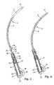
- FIG. 7the shaft, viewed normal to its plane of curvature
- FIG. 8a view of part of the shaft, where an incontinence strap has been attached thereto;
- FIG. 9a view of an end of a shaft of another embodiment that may either be attached to a grip, have an incontinence strap attached to it, or have a tip installed on it, drawn on a larger scale;
- FIG. 10a side view of another embodiment of an instrument for inserting an incontinence strap
- FIG. 11a top view of the same embodiment shown in FIG. 10 ;
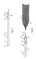
- FIG. 12an embodiment of an incontinence strap
- FIG. 13another embodiment of an incontinence strap
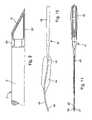
- FIG. 14an embodiment of an incontinence strap according to the invention having reinforced attachment devices
- FIG. 15a longitudinal section through the strap shown in FIG. 14 , where the sectioning is along the line A-A′ indicated in FIG. 14 , drawn on a much larger scale;
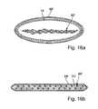
- FIG. 16 aa schematized view of the cross-section of an unbonded section of another embodiment of an incontinence strap according to the invention.
- FIG. 16 ba schematized view of the cross-section of the incontinence strap shown in FIG. 16 a in the vicinity of an attachment device, i.e., of a bonded section thereof.
- a shaft for inserting the incontinence strapis provided in the form of a curved, solid, stainless-steel needle 3 in the form a curved, circular rod 4 .
- the needlehas a conical tip 6 on an insertion end 5 . That may also be ground off at an angle such that the edge of the ground-off section lies on the inner side of the curvature.
- the tip of the needleis not sharp in order to prevent injuries to the abdominal organs when the incontinence strap is inserted.
- the needleessentially acts as a guiding appendage only.
- the end of the needle opposite that bearing the tip 6is configured in the form of an attachment end 7 and has devices for attaching it either to a grip 8 , or to the incontinence strap 2 .
- the grip 8consists of plastic or steel. It has a longitudinal section 9 that is essentially configured in the form of a hollow cylinder that is used both for accommodating and attaching the end 7 of the needle, and for gripping with the hand.
- the butt of the griphas a laterally broadened section 10 that essentially gives the grip a T-shape, is also used for gripping, and allows precisely controlled, lateral excursions of the needle.
- the attachment end 7 of the needle 3has a cylindrical section 11 having a diameter that is less than the normal diameter of the needle, has a beveled surface 12 on one side, or either side, and is separated from the circular rod 4 of the needle 3 by a circumferential groove 13 that forms an intervening cylindrical section having an even smaller diameter.
- This end of the needleis also is provided with an anti rotation lug that has a cross-section differing from the circular cross-section of the needle, in particular, an anti rotation lug in the form of a stamped flat 14 , in the vicinity of that section of the needle where the needle has its full diameter.
- the grip 8is symmetric with respect to the central plane of intersection orthogonal to the plane of the “T” and has in its interior a receptacle for holding the needle.
- the gripon its conically tapered attachment end 15 the grip has an insertion bore 16 whose inner diameter equals the normal diameter of the needle and also has a pair of lateral, flat-bottomed, longitudinal grooves 17 whose dimensions equal those of the stamped flat 14 on the needle and guarantee seating of the needle such that it will be constrained from rotating and be in the correct orientation with respect to the grip.
- the plane of curvature of the needleis orthogonal to the plane of the T-shaped grip.
- the walls of the hollow, cylindrical, longitudinal section 9 of the griphave a pair of thinner sections formed by mirror-image, with respect to the plane of the “T,” window-like recesses on diametrically opposite sides that are configured in the form of detenting prongs 18 .
- These detenting prongs 18are longitudinal leaf springs whose end facing the insertion aperture of the grip forms a unit with the material of the longitudinal section 9 and whose free end has a detenting protuberance 19 that faces inward. As shown in FIG. 4 , the detenting prongs 18 latch into position with their detenting protuberance 19 situated in the circumferential groove 13 on the end 7 of the needle, but are not self-locking.
- their detenting protuberances 19have flats on their sides facing toward, and away from, the direction of insertion, and may be flexed and spread apart both by the beveled surfaces 12 on the end of the needle aligned on them when the end 7 of the needle is inserted and by the shoulder 20 on the circumferential groove 13 when the end 7 of the needle is withdrawn.
- the detenting prongsare locked by a slide 21 in the form of a sleeve arranged within the grip that may be slid along the longitudinal axis of the grip that engages the outer surfaces of the detenting prongs 18 when in its locking position (cf. FIG.
- the slide 21releases the detenting prongs 18 and overlaps the end of the grip.
- Detenting elements 23 on the slide, together with associated active elements 24 on the gripprevent the slide 21 from falling off the grip when in its disengaged position.
- the gripmay be disassembled for cleaning, i.e., the slide 21 may be slid over the active elements 24 on the grip 8 and off the grip in order to remove it.
- the interior of the gripalso has a hollow section 25 that has an inner diameter that is less than that of the grip and equals the outer diameter of the cylindrical section 11 on the end 7 of the needle, and serves as a receptacle for that cylindrical section, which guarantees wobble-free seating of the needle in the grip.
- the strap 2is formed from a flat strip of cloth netting. Both ends of the strap are folded along the centerline 26 of the strap in order that its end sections 27 will be half as wide as the remainder of the strap and their planes will be orthogonal to the plane of the strap. These end sections 27 are firmly clamped in the flattened ends 28 of a retaining sleeve 29 on the end 7 of the needle that fits on the cylindrical section 11 thereof having a smaller diameter, and latches into position thereon.
- the retaining sleevehas the same outer diameter as the circular rod 4 of the needle.
- the free end 30 of the retaining sleeve 29is longitudinally slit, where the tips of the prongs formed thereby are either bent inward or configured such that they are thicker, snap into place in the circumferential groove 13 on the end of the needle, and reach around, and abut against, the circumferential shoulder 20 , in order that it may be attached to the end 7 of the needle.
- the strap 2may be attached to the needle 3 such that it cannot twist, in particular, is attached thereto oriented such that the plane of the strap lies in the plane of curvature of the needle.
- the single flat 12 (cf. FIG. 7 ) or pair of flats on the cylindrical section 11 of the needleinteract with the sloping surfaces 31 formed by the stamped flats on the retaining sleeve 29 for that purpose.
- other configurations of the anti twisting mechanismare feasible.
- the means for attaching the strapmay be such that they prevent successively attaching opposing ends of the strap to the same needle, i.e., prevent the same needle from being used twice during an operation.
- the retaining sleeve 29 on the end 7 of the needleis thus either permanently attached thereto, or may only be removed therefrom using a tool that has been specially designed for that purpose. This will preclude attachment of the other end of the strap to the end 7 of the needle and prevent reuse of the needle during the same operation.
- the needle 3together with the retaining sleeve 29 , are discarded after the strap 2 has been cut off. If the needle 3 is to be reused, the retaining sleeve 29 may be removed from the needle using the special tool before the needle is cleaned and sterilized.
- the needle 3 ′has tips 6 ′ on both ends by, for example, providing that its attachment end 7 is also pointed or has been ground off an angle.
- tips for the needleare configured such that they may be attached to the needle 3 ′, in particular, to the circular rod 4 ′, as shown in FIG. 9 .
- Both ends of the needlemay be configured such that tips 6 ′ may be attached thereto.
- both ends of the needlemay be configured similarly to its attachment end 7 ′.
- a sleeve 29 ′ having a tip 6 ′, instead of a retaining sleeve,may then be slipped onto the needle.
- the tipsare designed to be detachable and the retaining sleeve attached to the strap is slipped onto the needle once the tips have been detached.
- the instruments shown in FIGS. 1-9have a wide variety of applications due to the opportunities for varying their configurations that they provide, and may be used in surgery in which their shaft is inserted through the abdominal wall from above and guided downward, or, in the case of female patients, for example, inserted through the vaginal wall and guided upward to the abdominal wall from below.
- the strapmay be pulled through by the needle, as in suturing, by guiding the needle through the lower abdomen and allowing the needle to transport the strap along with it.
- the strapmay also be picked up by, for example, guiding the needle downward from the abdominal wall, attaching the strap to the accessible tip of the needle, and withdrawing the needle, along with the strap.
- the embodiment of an instrument for emplacing an incontinence strap shown in FIGS. 10 and 11has fewer prospective applications than the aforementioned instruments.
- the instrument 41 shown thereis more simply constructed and has several special features.
- the surgical instrument 41has a grip 42 and a shaft 43 that are configured in the form of a single, monolithic unit and beneficially consist of stainless steel.
- the grip 42is long and flat, but may also have another shape suitable for use on surgical instruments.
- the shaft 43follows a gentle S-curve.
- the shaftmay also be configured in the form of a curved rod having an essentially circular cross-section.
- the embodiment according to FIG. 10is intended for use in cases where the shaft is guided through the abdominal wall and downward, into the abdominal cavity.
- the purpose of the broadened section 44is giving the incision channel through the abdominal wall and the connective tissues and fatty tissues lying thereunder, and extending downward to the vaginal wall, a broadened shape that will roughly correspond to that of the incontinence strap. This broadening may essentially extend over the entire length of the shaft.
- the ends of the strap on the right and left of the urethramay be pulled upward, yielding a U-shaped noose reaching around the underside of the urethra.
- the tip of the shaftmay be configured such that it will allow attaching the strap such that the strap may be subsequently detached therefrom, in particular, may be configured such that it provides an attachment mechanism having a securing device that will prevent the strap from becoming unintentionally detached from the shaft.
- the tip 46 of the shaftis preferably configured in the form a so-called “Reverdin needle.” The latter has an eye that may be opened and closed and has a hooked shape when in the opened state.
- the attachment mechanism on the tip 46may also be configured differently, for example, by configuring the tip in the form of a simple eye, or by configuring the tip in the form of a detachable cap and providing that a coupling element, to which a mating coupling element on the strap may be attached, will be exposed when the tip is removed, as has been described in conjunction with FIG. 9 .
- the eyemay also be closed by means of a cap nut.
- the incontinence strap 51has longitudinal sections that differ from one another.
- Two end sections 52are configured in the form of coarse-weave textile straps that have rounded or tapered, V-shaped ends and holes, or other facilities, for attaching them to an insertion instrument.
- a midsection 53consists of resorbable plastic and is broadened, compared to its end sections 52 , on one side by a sort of curved extension. This section consists of smooth foil material, has smooth edges. It is intended to reach around the underside of the urethra.
- this section of the strapwhich represents a foreign object, will provide that sufficient tissue for supporting the urethra from below will be formed. Since the implant will thus have served its purpose, this particular section of the strap may be configured from resorbable material.
- the degradation period and resorption time of the material used for configuring the midsectionmay be predetermined in a known manner employing suitable copolymerization processes.
- the polymers that come into questionare synthetic polymers, in particular, such that may be obtained by polymerizing lactide, glycolide, trimethylene carbonate, dioxanone, ⁇ -caprolactone, or mixtures thereof.
- an incontinence strapthat is intended to remain in the body indefinitely is provided.
- the incontinence strap 61is subdivided into various sections, where at least one midsection 62 is configured in the form of a chamber that may be filled with a fluid, for example, water or liquid contrast media.
- the midsection 62or even the entire strap, may be configured in the form of a tube for that purpose.
- Various types of designs and materialsare available for configuring the strap.
- at least the strap's midsection and at least a channel section 63 bordering on its midsectionconsist of thermoplastic material.
- the fluid channel 65may be closed, for example, welded closed, once the chamber has been filled. It may also be accessible beneath the abdominal skin via a valve, for example, a pierceable membrane, that is accessible from outside.
- the chambermay also be formed from an elastomer, for example, silicone rubber, that is pierceable and self-sealing, in which case, no separate fluid channel will be required. It will also be feasible to configure the entire strap in the form of a tube and merely seal both ends. The only essential feature is that strap, complete with the chamber that may be filled, be in the form of a strip, which will allow the minimally invasive emplacement of the strap, without opening of the abdominal cavity being required.
- an elastomerfor example, silicone rubber
- FIG. 14depicts another embodiment of an incontinence strap 66 according to the invention.
- This incontinence strapis preferably configured such that it is elastic and porous, in particular, configured such that it consists of knit fabric, which will allow the ingrowth of tissue.
- This incontinence strap 66has an attachment device 67 on each end. These attachment devices are in the form of blunted tips. This will allow them to be easily guided through tissue in the desired directions, more safely than would be the case if they had corners or edges. Both attachment devices are identically configured.
- the incontinence strap 66also has an enshrouding sheath 68 that is configured such that it may be withdrawn therefrom due to the fact that it consists of two, separate segments ( 68 a , 68 b ), one of which is preferably inserted into the other at the middle of the strap, and overlaps the other.
- the sheathmay also be a one-piece construction, in which case it will have a perforation, preferably at its middle, that will simplify its separation into two segments.
- This sheathpreferably consists of a thermoplastic material, in particular, polyethylene. These sheaths simplify inserting the strap and protect it against contamination.
- the attachment devices 67are of multilayered construction.
- the upper layerconsists of a casing 69 that surrounds the sheath 68 in the vicinities of its attachment devices. Lying below, i.e., inward from, this casing 69 is a second layer, i.e., the sheath 68 .
- Another layer 70 of thermally bondable materiallies beneath the sheath 68 , i.e., between the sheath 68 and the strap 66 .
- the strap 66 , the layer 70 , the sheath 68 , and the casing 69are bonded together at the extremities of the incontinence strap.
- a rear section 71 of the attachment devices 67is left unbonded.
- the strapis bonded and reinforced over its full width, which will prevent its knit fabric from tearing off the laminate.
- a through hole 73 that may be punched during bonding in order that its edges will be compression bonded when the through hole is punchedis situated within the bonded section 72 of the laminate.
- the punched through holemay have various shapes, such as a triangular, rectangular, square, or, preferably, a circular or an elongated oval, shape.
- Each segment 68 a and 68 b of the sheathalso has an asymmetrically arranged, identifying line 75 a and 75 b .
- These identifying linespreferably have a readily recognized coloration.
- the two identifying lines 75 a and 75 bare parallel to one another in order that the operator may recognize the middle of the strap.
- All materials employedare preferably thermoplastic materials.
- the strap itselfpreferably consists of polypropylene, and, as mentioned above, the sheath preferably consists of, for example, polyethylene.
- the film thickness of the casing 69 and the layer 70 of bondable materialspreferably exceeds the film thickness of the sheath 68 . It will be beneficial if the sheath 68 has a film thickness of about 70 ⁇ m.
- the film thicknesses of the casing 69 and layer 70 of bondable materialshould preferably be about 200 ⁇ m.
- FIG. 15depicts a longitudinal section through the attachment device 67 at the transition zone between its bonded section 72 and unbonded section 71 , drawn on a much larger scale.
- the incontinence strap 66is situated at the center of the attachment device 67 .
- the incontinence strap 66is sandwiched between two layers 70 of bondable material. These layers of bondable material are followed by the sheath 68 .
- the film thickness of the sheath 68is much less than that of the layers 70 of bondable material.
- the outer faces of the attachment device 67are bounded by the casing 69 .
- the film thickness of the casing 69is approximately equal to the film thickness of the layers of bondable material.
- the aforementioned layersare thermally bonded together by welding covering an extended area.
- these layersare not unbonded together. However, it would be feasible to also bond, e.g., pointwise bond, these layers together, within section 71 .
- the attachment devices, together with the ends of the strapmay be cut off and the segments 68 a and 68 b of the sheath withdrawn along opposing directions. It will also be feasible to cut off just one half of the sheath and the ends of the strap, together with the attachment devices, and withdraw the ends of the strap, together with the segments of the sheath, along opposing directions.
- FIG. 16 adepicts a schematized view of the cross-section of an, as yet, unbonded section of the ends of another embodiment of an incontinence strap according to the invention.
- the incontinence strap 66 ′ and sheath 68 ′have an overall length of 31 cm and a width of 2 cm.
- the incontinence strap 66 ′is knitted and has pores, which will allow ingrowth of tissue.
- the ends of the incontinence strap 66 ′is encased in a casing 74 that has a length falling within the range 2 cm to 8 cm.
- the casing 74is, in turn, encased in the sheath 68 ′, which has already been described in conjunction with the preceding example of an embodiment.
- the casing 74which is arranged between the sheath 68 ′ and the end of the strap, encloses only a few centimeters of the long ends of the incontinence strap and serves as reinforcing material.
- the casing 74has a lower melting point than the incontinence strap 66 ′. That property of the casing 74 will allow it to act as a thermoplastic bond joining the sheath to the incontinence strap 66 ′ in the vicinities of the attachment devices (cf. FIG.
- the sheath 68 ′has a film thickness of about 70 ⁇ m and the casing 74 has a film thickness of about 200 ⁇ m. Both the sheath 68 ′ and the casing 74 consist of polyethylene.
- FIG. 16 bdepicts a schematized view of the cross-section of the incontinence strap shown in FIG. 16 a in the vicinity of an attachment device, i.e., of a bonded section thereof.
- Pressure and thermal treatment of the incontinence strap 66 ′, including its encasings, in the vicinities of its long endshave provided that its casing has melted and acts as a thermoplastic bond 74 ′ joining the sheath 68 ′ to the incontinence strap 66 ′.
- the material 74 ′ of the casingalso acts as a filler for filling the pores of the incontinence strap 66 ′.
- a through holeis situated within the bonded section, which, however, has not been depicted here.
- the total thickness of the laminate in the vicinity of the attachment deviceis about 650 ⁇ m.
Landscapes
- Health & Medical Sciences (AREA)
- Life Sciences & Earth Sciences (AREA)
- Urology & Nephrology (AREA)
- Animal Behavior & Ethology (AREA)
- General Health & Medical Sciences (AREA)
- Engineering & Computer Science (AREA)
- Biomedical Technology (AREA)
- Heart & Thoracic Surgery (AREA)
- Veterinary Medicine (AREA)
- Public Health (AREA)
- Vascular Medicine (AREA)
- Cardiology (AREA)
- Oral & Maxillofacial Surgery (AREA)
- Transplantation (AREA)
- Surgery (AREA)
- Nuclear Medicine, Radiotherapy & Molecular Imaging (AREA)
- Medical Informatics (AREA)
- Molecular Biology (AREA)
- Orthopedics, Nursing, And Contraception (AREA)
- Prostheses (AREA)
- Absorbent Articles And Supports Therefor (AREA)
Abstract
Description
Claims (42)
Applications Claiming Priority (7)
| Application Number | Priority Date | Filing Date | Title |
|---|---|---|---|
| DE10138950.7 | 2001-08-03 | ||
| DE2001138950DE10138950A1 (en) | 2001-08-03 | 2001-08-03 | Strip for treating urinary incontinence, especially for women, by implantation in abdomen, is flexible and preferably consists (partly) of resorbable material, e.g. polyvinyl alcohol |
| DE10138950 | 2001-08-03 | ||
| DE20204669UDE20204669U1 (en) | 2002-03-23 | 2002-03-23 | Strip for treating urinary incontinence, especially for women, by implantation in abdomen, is flexible and preferably consists (partly) of resorbable material, e.g. polyvinyl alcohol |
| DE20204669U | 2002-03-23 | ||
| DE20204669.9 | 2002-03-23 | ||
| PCT/EP2002/008570WO2003013392A1 (en) | 2001-08-03 | 2002-08-01 | Incontinence strip for treating urinary incontinence |
Publications (2)
| Publication Number | Publication Date |
|---|---|
| US20040249240A1 US20040249240A1 (en) | 2004-12-09 |
| US7351196B2true US7351196B2 (en) | 2008-04-01 |
Family
ID=26009907
Family Applications (1)
| Application Number | Title | Priority Date | Filing Date |
|---|---|---|---|
| US10/485,567Expired - Fee RelatedUS7351196B2 (en) | 2001-08-03 | 2002-08-01 | Incontinence strip for treating urinary incontinence |
Country Status (6)
| Country | Link |
|---|---|
| US (1) | US7351196B2 (en) |
| EP (3) | EP1411858B1 (en) |
| AT (1) | ATE332674T1 (en) |
| DE (1) | DE50207513D1 (en) |
| ES (1) | ES2269745T3 (en) |
| WO (1) | WO2003013392A1 (en) |
Cited By (33)
| Publication number | Priority date | Publication date | Assignee | Title |
|---|---|---|---|---|
| US20020151909A1 (en)* | 2001-03-09 | 2002-10-17 | Gellman Barry N. | System for implanting an implant and method thereof |
| US20070299299A1 (en)* | 2004-12-20 | 2007-12-27 | Ams Research Corporation | System and Method for Treatment of Anal Incontinence and Pelvic Organ Prolapse |
| US20080300607A1 (en)* | 2005-12-28 | 2008-12-04 | C.R. Bard, Inc. | Apparatus and Method for Introducing Implants |
| US20090023978A1 (en)* | 2005-02-04 | 2009-01-22 | Arnal Kevin R | Needle design for male transobturator sling |
| US20090156891A1 (en)* | 2007-12-12 | 2009-06-18 | Ams Research Corporation | Prolapse and Perineal Repair Concepts |
| US20090192346A1 (en)* | 2004-12-20 | 2009-07-30 | Ams Research Corporation | Treatment of anal incontinence and defecatory dysfunction |
| US20090240104A1 (en)* | 2007-10-26 | 2009-09-24 | Ams Research Corporation | Surgical Articles and Methods for Treating Pelvic Conditions |
| US20100010631A1 (en)* | 2006-05-19 | 2010-01-14 | John Fritz Otte | Method and articles for treatment of stress urinary incontinence |
| US20100094079A1 (en)* | 2005-06-21 | 2010-04-15 | Ams Research Corporation | Method and Apparatus for Securing a Urethral Sling to Pubic Bone |
| US20100105979A1 (en)* | 2008-10-27 | 2010-04-29 | Ams Research Corporation | Surgical Needle and Anchor System with Retractable Features |
| US20100121460A1 (en)* | 2007-03-07 | 2010-05-13 | D Afiero Alessandro | Prosthesis for the treatment of urinary incontinence |
| US20100168505A1 (en)* | 2005-06-21 | 2010-07-01 | Ams Research Corporation | Methods and apparatus for securing a urethral sling to a pubic bone |
| US20110034759A1 (en)* | 2006-10-26 | 2011-02-10 | Ogdahl Jason W | Surgical articles and methods for treating pelvic conditions |
| US20110082328A1 (en)* | 2007-01-03 | 2011-04-07 | Christian Gozzi | Methods for installing sling to treat fecal incontinence, and related devices |
| US20110160527A1 (en)* | 2009-12-31 | 2011-06-30 | Ams Research Corporation | Suture-less Tissue Fixation for Implantable Device |
| US7972262B2 (en) | 2001-01-23 | 2011-07-05 | Ams Research Corporation | Sling assembly with secure and convenient attachment |
| US8206280B2 (en) | 2007-11-13 | 2012-06-26 | C. R. Bard, Inc. | Adjustable tissue support member |
| US8480559B2 (en) | 2006-09-13 | 2013-07-09 | C. R. Bard, Inc. | Urethral support system |
| US8628463B2 (en) | 2006-06-22 | 2014-01-14 | Ams Research Corporation | Adjustable tension incontinence sling assemblies |
| US8708885B2 (en) | 2007-09-21 | 2014-04-29 | Ams Research Corporation | Pelvic floor treatments and related tools and implants |
| US8834350B2 (en) | 2006-06-16 | 2014-09-16 | Ams Research Corporation | Surgical implants, tools, and methods for treating pelvic conditions |
| US8845512B2 (en) | 2005-11-14 | 2014-09-30 | C. R. Bard, Inc. | Sling anchor system |
| USD721175S1 (en) | 2011-09-08 | 2015-01-13 | Ams Research Corporation | Backers for surgical indicators |
| USD721807S1 (en) | 2011-09-08 | 2015-01-27 | Ams Research Corporation | Surgical indicators |
| USD736382S1 (en) | 2011-09-08 | 2015-08-11 | Ams Research Corporation | Surgical indicator with backers |
| US9125717B2 (en) | 2011-02-23 | 2015-09-08 | Ams Research Corporation | Implant tension adjustment system and method |
| US9226809B2 (en) | 2009-02-10 | 2016-01-05 | Ams Research Corporation | Surgical articles and methods for treating urinary incontinence |
| US9345473B2 (en) | 2009-12-30 | 2016-05-24 | Astora Women's Health, Llc | Implantable sling systems and methods |
| US9381076B2 (en) | 2010-02-23 | 2016-07-05 | Boston Scientific Scimed, Inc. | Surgical articles and methods |
| US9445881B2 (en) | 2010-02-23 | 2016-09-20 | Boston Scientific Scimed, Inc. | Surgical articles and methods |
| US10500027B2 (en) | 2011-06-30 | 2019-12-10 | Boston Scientific Scimed, Inc. | Implants, tools, and methods for treatments of pelvic conditions |
| WO2022099054A1 (en)* | 2020-11-06 | 2022-05-12 | Vita Solutions LLC | Surgical delivery devices, systems, and methods |
| US11865331B2 (en) | 2008-05-12 | 2024-01-09 | Advanced Neuromodulation Systems, Inc. | Peripheral nerve field stimulator curved subcutaneous introducer needle with wing attachment specification |
Families Citing this family (57)
| Publication number | Priority date | Publication date | Assignee | Title |
|---|---|---|---|---|
| US6638211B2 (en) | 2000-07-05 | 2003-10-28 | Mentor Corporation | Method for treating urinary incontinence in women and implantable device intended to correct urinary incontinence |
| FR2811218B1 (en) | 2000-07-05 | 2003-02-28 | Patrice Suslian | IMPLANTABLE DEVICE FOR CORRECTING URINARY INCONTINENCE |
| US8167785B2 (en) | 2000-10-12 | 2012-05-01 | Coloplast A/S | Urethral support system |
| US20060205995A1 (en) | 2000-10-12 | 2006-09-14 | Gyne Ideas Limited | Apparatus and method for treating female urinary incontinence |
| GB0025068D0 (en) | 2000-10-12 | 2000-11-29 | Browning Healthcare Ltd | Apparatus and method for treating female urinary incontinence |
| US8033983B2 (en) | 2001-03-09 | 2011-10-11 | Boston Scientific Scimed, Inc. | Medical implant |
| GB0108088D0 (en) | 2001-03-30 | 2001-05-23 | Browning Healthcare Ltd | Surgical implant |
| US6974462B2 (en)* | 2001-12-19 | 2005-12-13 | Boston Scientific Scimed, Inc. | Surgical anchor implantation device |
| MXPA04008407A (en) | 2002-03-01 | 2005-12-12 | Ethicon Inc | Method and apparatus for treating pelvic organ prolapses in female patients. |
| US8968178B2 (en) | 2002-03-07 | 2015-03-03 | Ams Research Corporation | Transobturator surgical articles and methods |
| ES2211286B1 (en)* | 2002-05-29 | 2005-10-01 | Jesus Romero Maroto | IMPROVED SYSTEM FOR THE TREATMENT OF URINARY INCONTINENCE OF EFFORT. |
| AU2003253106A1 (en)* | 2002-07-04 | 2004-01-23 | Gyne Ideas Ltd | Medical implant |
| CA2492630C (en) | 2002-08-02 | 2009-01-13 | C.R. Bard, Inc. | Self anchoring sling and introducer system |
| GB0307082D0 (en) | 2003-03-27 | 2003-04-30 | Gyne Ideas Ltd | Drug delivery device and method |
| EP1610714A2 (en)* | 2003-03-28 | 2006-01-04 | Analytic Biosurgical Solutions - ABISS | Implant for treatment of a rectocele and device for placement of said implant |
| US7494495B2 (en)* | 2003-03-28 | 2009-02-24 | Coloplast A/S | Method and implant for curing cystocele |
| US7361138B2 (en) | 2003-07-31 | 2008-04-22 | Scimed Life Systems, Inc. | Bioabsorbable casing for surgical sling assembly |
| DE602004023314D1 (en) | 2003-08-14 | 2009-11-05 | Boston Scient Ltd | SURGICAL SLINGS |
| US8545386B2 (en)* | 2003-08-14 | 2013-10-01 | Boston Scientific Scimed, Inc. | Surgical slings |
| US8062206B2 (en) | 2004-05-07 | 2011-11-22 | Ams Research Corporation | Method and apparatus for treatment of vaginal anterior repairs |
| GB0411360D0 (en) | 2004-05-21 | 2004-06-23 | Mpathy Medical Devices Ltd | Implant |
| EP3087949B1 (en) | 2004-06-14 | 2018-07-25 | Boston Scientific Limited | System relating to implantable supportive slings |
| FR2871361B1 (en)* | 2004-06-15 | 2006-09-29 | Analytic Biosurgical Solutions | SURGICAL ANCHORING DEVICE |
| US20050288708A1 (en)* | 2004-06-25 | 2005-12-29 | Kammerer Gene W | Soft tissue fastener having integral biasing section |
| US7527588B2 (en) | 2004-09-15 | 2009-05-05 | Ethicon, Inc. | System and method for surgical implant placement |
| CA2591493C (en)* | 2004-12-20 | 2014-10-28 | Peter L. Rosenblatt | Treatment of anal incontinence |
| US7481314B2 (en) | 2005-02-02 | 2009-01-27 | Ethicon, Inc. | Packaging assembly for surgical mesh implants |
| US7914437B2 (en)* | 2005-02-04 | 2011-03-29 | Ams Research Corporation | Transobturator methods for installing sling to treat incontinence, and related devices |
| JP5058969B2 (en) | 2005-04-06 | 2012-10-24 | ボストン サイエンティフィック リミテッド | System, apparatus and method for suburethral support |
| US7393320B2 (en) | 2005-04-29 | 2008-07-01 | Ams Research Corporation | Pelvic floor health articles and procedures |
| DE102005021881A1 (en)* | 2005-05-04 | 2006-11-09 | Aesculap Ag & Co. Kg | urinary incontinence band |
| DE102005021893A1 (en)* | 2005-05-04 | 2006-11-09 | Aesculap Ag & Co. Kg | Device for the prevention of urinary incontinence in humans |
| WO2007008209A1 (en) | 2005-07-13 | 2007-01-18 | Boston Scientific Scimed Inc. | Snap fit sling anchor system and related methods |
| WO2007011341A1 (en)* | 2005-07-15 | 2007-01-25 | Boston Scientific Scimed, Inc. | A tension-adjustable surgical sling assembly |
| EP2974692B1 (en) | 2005-07-25 | 2019-03-13 | Boston Scientific Limited | Pelvic floor repair system |
| US7981023B2 (en)* | 2005-07-25 | 2011-07-19 | Boston Scientific Scimed, Inc. | Elastic sling system and related methods |
| WO2007059368A1 (en)* | 2005-11-11 | 2007-05-24 | Ams Research Corporation | Integral sling connection system and method |
| JP4468889B2 (en)* | 2005-12-26 | 2010-05-26 | 日本シャーウッド株式会社 | Medical needle reinforcement |
| US8059625B2 (en)* | 2006-02-03 | 2011-11-15 | Motorola Mobility, Inc. | Distributed architecture and methods for broadcast/multicast service |
| CA2908132C (en) | 2006-02-16 | 2018-12-11 | Ams Research Corporation | Surgical articles and methods for treating pelvic conditions |
| AU2007311067A1 (en) | 2006-10-18 | 2008-04-24 | Coloplast A/S | Implantable devices for the treatment of incontinence and methods of using the same |
| US8684907B2 (en)* | 2007-02-26 | 2014-04-01 | Jay S. Hortenstine | Adjustable incontinence apparatus |
| CA2695212C (en)* | 2007-07-30 | 2017-11-28 | Boston Scientific Scimed, Inc. | Apparatus and method for the treatment of stress urinary incontinence |
| US20090187066A1 (en)* | 2007-09-18 | 2009-07-23 | The Cleveland Clinic Foundation | Apparatus and method for treating urinary incontinence |
| US8430807B2 (en) | 2007-12-28 | 2013-04-30 | Boston Scientific Scimed, Inc. | Devices and methods for treating pelvic floor dysfunctions |
| FR2941366B1 (en)* | 2009-01-28 | 2011-02-25 | Cie Euro Etude Rech Paroscopie | GASTRIC RING WITH ROD |
| US9125716B2 (en)* | 2009-04-17 | 2015-09-08 | Boston Scientific Scimed, Inc. | Delivery sleeve for pelvic floor implants |
| DK200900718A (en) | 2009-06-08 | 2010-12-09 | Coloplast As | Anatomical augmentation device |
| US20110040313A1 (en)* | 2009-08-14 | 2011-02-17 | Dlugos Jr Daniel F | Implantable restriction device with protective member |
| US9113991B2 (en) | 2011-05-12 | 2015-08-25 | Boston Scientific Scimed, Inc. | Anchors for bodily implants and methods for anchoring bodily implants into a patient's body |
| US9636201B2 (en) | 2011-05-12 | 2017-05-02 | Boston Scientific Scimed, Inc. | Delivery members for delivering an implant into a body of a patient |
| CN104321035B (en)* | 2012-08-27 | 2016-05-18 | 泰尔茂株式会社 | Medical tube and medical tube assembly |
| US10111651B2 (en) | 2012-11-02 | 2018-10-30 | Coloplast A/S | System and method of anchoring support material to tissue |
| US9241779B2 (en) | 2012-11-02 | 2016-01-26 | Coloplast A/S | Male incontinence treatment system |
| WO2014162432A1 (en)* | 2013-04-01 | 2014-10-09 | テルモ株式会社 | Medical tube and medical tube assembly |
| US9480546B2 (en) | 2013-08-05 | 2016-11-01 | Coloplast A/S | Hysteropexy mesh apparatuses and methods |
| US9522000B2 (en) | 2013-11-08 | 2016-12-20 | Coloplast A/S | System and a method for surgical suture fixation |
Citations (30)
| Publication number | Priority date | Publication date | Assignee | Title |
|---|---|---|---|---|
| US4587954A (en) | 1983-12-29 | 1986-05-13 | Habley Medical Technology Corporation | Elastomeric prosthetic sphincter |
| US4709690A (en) | 1986-04-21 | 1987-12-01 | Habley Medical Technology Corporation | Implantable blood flow and occlusion pressure sensing sphincteric system |
| WO1990001016A1 (en) | 1988-07-22 | 1990-02-08 | Centre National De La Recherche Scientifique (Cnrs) | Mecanochemical preparation of carbides and silicides |
| WO1991000069A1 (en) | 1989-06-28 | 1991-01-10 | Johann Rull | Prosthesis for preventing incontinence of the urinary tract in women |
| US5112344A (en) | 1988-10-04 | 1992-05-12 | Petros Peter E | Surgical instrument and method of utilization of such |
| DE4220283C2 (en) | 1992-06-20 | 1994-05-19 | Singer Spezialnadelfab | Surgical needle-thread combination |
| EP0639355A1 (en) | 1993-08-21 | 1995-02-22 | RULL, Johann, Dr. med. | Prosthesis for controlling urinary incontinence in women |
| WO1998035632A1 (en) | 1997-02-13 | 1998-08-20 | Boston Scientific Ireland Limited | Stabilization sling for use in minimally invasive pelvic surgery |
| US5899909A (en) | 1994-08-30 | 1999-05-04 | Medscand Medical Ab | Surgical instrument for treating female urinary incontinence |
| WO2000009039A1 (en) | 1998-08-13 | 2000-02-24 | Contimed, Inc. | Bladder sling |
| US6030393A (en) | 1998-09-15 | 2000-02-29 | Corlew; Earvin L. | Needle and procedure for relieving urinary incontinence |
| WO2000018319A1 (en) | 1998-09-30 | 2000-04-06 | Burger, Nicolaas, Daniel, Lombard | Distensible sling for urinary incontinence |
| WO2000027304A1 (en) | 1998-11-10 | 2000-05-18 | Sofradim Production | Suspension device for treating prolapsus and urinary incontinence |
| US6110101A (en) | 1998-08-13 | 2000-08-29 | Conticare Medical, Inc. | Bladder sling |
| WO2000074613A1 (en) | 1999-06-09 | 2000-12-14 | Ethicon, Inc. | Visually-directed surgical instrument and method for treating female urinary incontinence |
| WO2000074633A2 (en) | 1999-06-09 | 2000-12-14 | Ethicon, Inc. | Method and apparatus for adjusting flexible areal polymer implants |
| EP1093758A1 (en) | 1999-10-22 | 2001-04-25 | Kaladelfos, George | Suture insertion device for the treatment of urinary stress incontinence |
| EP1108393A2 (en) | 1999-12-15 | 2001-06-20 | Ethicon GmbH | Surgical needle for implanting a tape |
| WO2001045589A1 (en) | 1999-12-22 | 2001-06-28 | Promedon | Sling with pad treatment of urinary incontinence |
| DE10103179A1 (en) | 2000-01-21 | 2001-07-26 | Sofradim Production Trevoux | Device for treating stress induced urinal incontinence in female patients comprises a puncture needle whose proximal end is joined to the distal end of a flexible element by means of an element capable of exerting a pull |
| DE19964081A1 (en) | 1999-12-29 | 2001-07-26 | Ethicon Gmbh | Strip-like implant |
| DE20109379U1 (en) | 2001-06-06 | 2001-09-27 | Stein, Bernd, Dr., 79104 Freiburg | Surgical surgical instrument |
| FR2814939A1 (en) | 2000-10-05 | 2002-04-12 | Sofradim Production | SUB-URETRAL SUPPORT KIT FOR THE TREATMENT OF URINARY INCONTINENCE OF FEMALE EXERCISE |
| US20020099258A1 (en)* | 2001-01-23 | 2002-07-25 | Staskin David R. | Sling delivery system and method of use |
| US6432040B1 (en)* | 2000-09-14 | 2002-08-13 | Nizam N. Meah | Implantable esophageal sphincter apparatus for gastroesophageal reflux disease and method |
| WO2002065921A1 (en) | 2001-02-17 | 2002-08-29 | Siegfried Riek | Instrumentation for the operative treatment of urinary incontinence in women |
| US20020165566A1 (en) | 1995-10-09 | 2002-11-07 | Ulf Ulmsten | Surgical instrument and method for treating female urinary incontinence |
| US20020193517A1 (en)* | 2001-03-12 | 2002-12-19 | Wang James H. | Water-responsive biodegradable polymer compositions and method of making same |
| US20030004391A1 (en) | 2001-04-03 | 2003-01-02 | Hitachi, Ltd. | Radioactive substance decontamination method and apparatus |
| US6652450B2 (en)* | 2001-01-23 | 2003-11-25 | American Medical Systems, Inc. | Implantable article and method for treating urinary incontinence using means for repositioning the implantable article |
- 2002
- 2002-08-01WOPCT/EP2002/008570patent/WO2003013392A1/enactiveIP Right Grant
- 2002-08-01DEDE50207513Tpatent/DE50207513D1/ennot_activeExpired - Lifetime
- 2002-08-01USUS10/485,567patent/US7351196B2/ennot_activeExpired - Fee Related
- 2002-08-01EPEP02754967Apatent/EP1411858B1/ennot_activeExpired - Lifetime
- 2002-08-01EPEP06006098Apatent/EP1666001A1/ennot_activeWithdrawn
- 2002-08-01EPEP05007936Apatent/EP1552796A3/ennot_activeWithdrawn
- 2002-08-01ESES02754967Tpatent/ES2269745T3/ennot_activeExpired - Lifetime
- 2002-08-01ATAT02754967Tpatent/ATE332674T1/enactive
Patent Citations (39)
| Publication number | Priority date | Publication date | Assignee | Title |
|---|---|---|---|---|
| US4587954A (en) | 1983-12-29 | 1986-05-13 | Habley Medical Technology Corporation | Elastomeric prosthetic sphincter |
| US4709690A (en) | 1986-04-21 | 1987-12-01 | Habley Medical Technology Corporation | Implantable blood flow and occlusion pressure sensing sphincteric system |
| WO1990001016A1 (en) | 1988-07-22 | 1990-02-08 | Centre National De La Recherche Scientifique (Cnrs) | Mecanochemical preparation of carbides and silicides |
| EP0437481B1 (en) | 1988-10-04 | 1995-03-15 | PETROS Peter Emmanuel | Surgical instrument prosthesis |
| US5112344A (en) | 1988-10-04 | 1992-05-12 | Petros Peter E | Surgical instrument and method of utilization of such |
| WO1991000069A1 (en) | 1989-06-28 | 1991-01-10 | Johann Rull | Prosthesis for preventing incontinence of the urinary tract in women |
| DE4220283C2 (en) | 1992-06-20 | 1994-05-19 | Singer Spezialnadelfab | Surgical needle-thread combination |
| EP0639355A1 (en) | 1993-08-21 | 1995-02-22 | RULL, Johann, Dr. med. | Prosthesis for controlling urinary incontinence in women |
| US5899909A (en) | 1994-08-30 | 1999-05-04 | Medscand Medical Ab | Surgical instrument for treating female urinary incontinence |
| US20020165566A1 (en) | 1995-10-09 | 2002-11-07 | Ulf Ulmsten | Surgical instrument and method for treating female urinary incontinence |
| US6491703B1 (en) | 1995-10-09 | 2002-12-10 | Ethicon, Inc. | Surgical instrument for treating female urinary incontinence |
| WO1998035632A1 (en) | 1997-02-13 | 1998-08-20 | Boston Scientific Ireland Limited | Stabilization sling for use in minimally invasive pelvic surgery |
| US6042534A (en) | 1997-02-13 | 2000-03-28 | Scimed Life Systems, Inc. | Stabilization sling for use in minimally invasive pelvic surgery |
| WO2000009039A1 (en) | 1998-08-13 | 2000-02-24 | Contimed, Inc. | Bladder sling |
| US6110101A (en) | 1998-08-13 | 2000-08-29 | Conticare Medical, Inc. | Bladder sling |
| US6030393A (en) | 1998-09-15 | 2000-02-29 | Corlew; Earvin L. | Needle and procedure for relieving urinary incontinence |
| WO2000018319A1 (en) | 1998-09-30 | 2000-04-06 | Burger, Nicolaas, Daniel, Lombard | Distensible sling for urinary incontinence |
| US6786861B1 (en) | 1998-10-01 | 2004-09-07 | Nicolaas Daniel Lombard Burger | Distensible sling for urinary incontinence |
| WO2000027304A1 (en) | 1998-11-10 | 2000-05-18 | Sofradim Production | Suspension device for treating prolapsus and urinary incontinence |
| WO2000074613A1 (en) | 1999-06-09 | 2000-12-14 | Ethicon, Inc. | Visually-directed surgical instrument and method for treating female urinary incontinence |
| WO2000074633A2 (en) | 1999-06-09 | 2000-12-14 | Ethicon, Inc. | Method and apparatus for adjusting flexible areal polymer implants |
| US6475139B1 (en) | 1999-06-09 | 2002-11-05 | Ethicon, Inc. | Visually-directed surgical instrument and method for treating female urinary incontinence |
| EP1093758A1 (en) | 1999-10-22 | 2001-04-25 | Kaladelfos, George | Suture insertion device for the treatment of urinary stress incontinence |
| US6494887B1 (en) | 1999-10-22 | 2002-12-17 | George Kaladelfos | Surgical instrument |
| EP1108393A2 (en) | 1999-12-15 | 2001-06-20 | Ethicon GmbH | Surgical needle for implanting a tape |
| FR2802798A1 (en) | 1999-12-22 | 2001-06-29 | Promedon S A | Sling for treatment of urinary incontinence, comprises band having pad(s) on middle part |
| WO2001045589A1 (en) | 1999-12-22 | 2001-06-28 | Promedon | Sling with pad treatment of urinary incontinence |
| DE19964081A1 (en) | 1999-12-29 | 2001-07-26 | Ethicon Gmbh | Strip-like implant |
| GB2359256A (en) | 2000-01-21 | 2001-08-22 | Sofradim Production | Percutaneous device for treating urinary stress incontinence in women using a sub-urethral tape |
| DE10103179A1 (en) | 2000-01-21 | 2001-07-26 | Sofradim Production Trevoux | Device for treating stress induced urinal incontinence in female patients comprises a puncture needle whose proximal end is joined to the distal end of a flexible element by means of an element capable of exerting a pull |
| US6432040B1 (en)* | 2000-09-14 | 2002-08-13 | Nizam N. Meah | Implantable esophageal sphincter apparatus for gastroesophageal reflux disease and method |
| US20030004395A1 (en) | 2000-10-05 | 2003-01-02 | Sofradim Production | Suburethral support assembly in treatment of female urinary stress incontinence |
| FR2814939A1 (en) | 2000-10-05 | 2002-04-12 | Sofradim Production | SUB-URETRAL SUPPORT KIT FOR THE TREATMENT OF URINARY INCONTINENCE OF FEMALE EXERCISE |
| US20020099258A1 (en)* | 2001-01-23 | 2002-07-25 | Staskin David R. | Sling delivery system and method of use |
| US6652450B2 (en)* | 2001-01-23 | 2003-11-25 | American Medical Systems, Inc. | Implantable article and method for treating urinary incontinence using means for repositioning the implantable article |
| WO2002065921A1 (en) | 2001-02-17 | 2002-08-29 | Siegfried Riek | Instrumentation for the operative treatment of urinary incontinence in women |
| US20020193517A1 (en)* | 2001-03-12 | 2002-12-19 | Wang James H. | Water-responsive biodegradable polymer compositions and method of making same |
| US20030004391A1 (en) | 2001-04-03 | 2003-01-02 | Hitachi, Ltd. | Radioactive substance decontamination method and apparatus |
| DE20109379U1 (en) | 2001-06-06 | 2001-09-27 | Stein, Bernd, Dr., 79104 Freiburg | Surgical surgical instrument |
Cited By (70)
| Publication number | Priority date | Publication date | Assignee | Title |
|---|---|---|---|---|
| US8784295B2 (en) | 2001-01-23 | 2014-07-22 | Ams Research Corporation | Sling assembly with secure and convenient attachment |
| US20110230704A1 (en)* | 2001-01-23 | 2011-09-22 | Ams Research Corporation | Sling Assembly with Secure and Convenient Attachment |
| US7972262B2 (en) | 2001-01-23 | 2011-07-05 | Ams Research Corporation | Sling assembly with secure and convenient attachment |
| US8617048B2 (en) | 2001-03-09 | 2013-12-31 | Boston Scientific Scimed, Inc. | System for implanting an implant and method thereof |
| US8162816B2 (en) | 2001-03-09 | 2012-04-24 | Boston Scientific Scimed, Inc. | System for implanting an implant and method thereof |
| US20020151909A1 (en)* | 2001-03-09 | 2002-10-17 | Gellman Barry N. | System for implanting an implant and method thereof |
| US9480545B2 (en) | 2004-12-20 | 2016-11-01 | Astora Women's Health, Llc | System and method for treatment of anal incontinence and pelvic organ prolapse |
| US8678991B2 (en) | 2004-12-20 | 2014-03-25 | Ams Research Corporation | System for treatment of anal incontinence |
| US8852076B2 (en) | 2004-12-20 | 2014-10-07 | Ams Research Corporation | System and method for treatment of anal incontinence and pelvic organ prolapse |
| US8449447B2 (en) | 2004-12-20 | 2013-05-28 | Ams Research Corporation | System and method for treatment of anal incontinence and pelvic organ prolapse |
| US8172745B2 (en) | 2004-12-20 | 2012-05-08 | Ams Research Corporation | Treatment of anal incontinence and defecatory dysfunction |
| US10285792B2 (en) | 2004-12-20 | 2019-05-14 | Rosenblatt Associates, Llc | System and method for treatment of anal incontinence and pelvic organ prolapse |
| US7794385B2 (en) | 2004-12-20 | 2010-09-14 | Ams Research Corporation | System and method for treatment of anal incontinence and pelvic organ prolapse |
| US20100331609A1 (en)* | 2004-12-20 | 2010-12-30 | Ams Research Corporation | System and method for treatment of anal incontinence and pelvic organ prolapse |
| US20090192346A1 (en)* | 2004-12-20 | 2009-07-30 | Ams Research Corporation | Treatment of anal incontinence and defecatory dysfunction |
| US20070299299A1 (en)* | 2004-12-20 | 2007-12-27 | Ams Research Corporation | System and Method for Treatment of Anal Incontinence and Pelvic Organ Prolapse |
| US20090023978A1 (en)* | 2005-02-04 | 2009-01-22 | Arnal Kevin R | Needle design for male transobturator sling |
| US8070672B2 (en) | 2005-02-04 | 2011-12-06 | Ams Research Corporation | Needle design for male transobturator sling |
| US20100094079A1 (en)* | 2005-06-21 | 2010-04-15 | Ams Research Corporation | Method and Apparatus for Securing a Urethral Sling to Pubic Bone |
| US20100168505A1 (en)* | 2005-06-21 | 2010-07-01 | Ams Research Corporation | Methods and apparatus for securing a urethral sling to a pubic bone |
| US9549799B2 (en) | 2005-06-21 | 2017-01-24 | Boston Scientific Scimed, Inc. | Surgical kit for securing an implantable sling in a pubic region |
| US8864650B2 (en) | 2005-06-21 | 2014-10-21 | Ams Research Corporation | Methods and apparatus for securing a urethral sling to a pubic bone |
| US8845512B2 (en) | 2005-11-14 | 2014-09-30 | C. R. Bard, Inc. | Sling anchor system |
| US20080300607A1 (en)* | 2005-12-28 | 2008-12-04 | C.R. Bard, Inc. | Apparatus and Method for Introducing Implants |
| US20100010501A2 (en)* | 2005-12-28 | 2010-01-14 | C.R. Bard, Inc. | Apparatus and method for introducing implants |
| US20100010631A1 (en)* | 2006-05-19 | 2010-01-14 | John Fritz Otte | Method and articles for treatment of stress urinary incontinence |
| US9084664B2 (en) | 2006-05-19 | 2015-07-21 | Ams Research Corporation | Method and articles for treatment of stress urinary incontinence |
| US10271936B2 (en) | 2006-06-16 | 2019-04-30 | Boston Scientific Scimed, Inc. | Surgical implants, tools, and methods for treating pelvic conditions |
| US8834350B2 (en) | 2006-06-16 | 2014-09-16 | Ams Research Corporation | Surgical implants, tools, and methods for treating pelvic conditions |
| US9375302B2 (en) | 2006-06-22 | 2016-06-28 | Astora Women's Health, Llc | Adjustable tension incontinence sling assemblies |
| US8628463B2 (en) | 2006-06-22 | 2014-01-14 | Ams Research Corporation | Adjustable tension incontinence sling assemblies |
| US10441400B2 (en) | 2006-06-22 | 2019-10-15 | Boston Scientific Scimed, Inc. | Adjustable tension incontinence sling assembles |
| US8480559B2 (en) | 2006-09-13 | 2013-07-09 | C. R. Bard, Inc. | Urethral support system |
| US8388514B2 (en) | 2006-10-26 | 2013-03-05 | Ams Research Corporation | Surgical articles and methods for treating pelvic conditions |
| US8777837B2 (en) | 2006-10-26 | 2014-07-15 | Ams Research Corporation | Surgical articles and methods for treating pelvic |
| US9585739B2 (en) | 2006-10-26 | 2017-03-07 | Ams Research Corporation | Surgical articles and methods for treating pelvic conditions |
| US20110034759A1 (en)* | 2006-10-26 | 2011-02-10 | Ogdahl Jason W | Surgical articles and methods for treating pelvic conditions |
| US20110082328A1 (en)* | 2007-01-03 | 2011-04-07 | Christian Gozzi | Methods for installing sling to treat fecal incontinence, and related devices |
| US20100121460A1 (en)* | 2007-03-07 | 2010-05-13 | D Afiero Alessandro | Prosthesis for the treatment of urinary incontinence |
| US8708885B2 (en) | 2007-09-21 | 2014-04-29 | Ams Research Corporation | Pelvic floor treatments and related tools and implants |
| US10010394B2 (en) | 2007-09-21 | 2018-07-03 | Boston Scientific Scimed, Inc. | Pelvic floor treatments and related tools and implants |
| US9333065B2 (en) | 2007-09-21 | 2016-05-10 | Astora Women's Health, Llc | Pelvic floor treatments and related tools and implants |
| US8951185B2 (en) | 2007-10-26 | 2015-02-10 | Ams Research Corporation | Surgical articles and methods for treating pelvic conditions |
| US20090240104A1 (en)* | 2007-10-26 | 2009-09-24 | Ams Research Corporation | Surgical Articles and Methods for Treating Pelvic Conditions |
| US8206280B2 (en) | 2007-11-13 | 2012-06-26 | C. R. Bard, Inc. | Adjustable tissue support member |
| US8574149B2 (en) | 2007-11-13 | 2013-11-05 | C. R. Bard, Inc. | Adjustable tissue support member |
| US20090156891A1 (en)* | 2007-12-12 | 2009-06-18 | Ams Research Corporation | Prolapse and Perineal Repair Concepts |
| US11865331B2 (en) | 2008-05-12 | 2024-01-09 | Advanced Neuromodulation Systems, Inc. | Peripheral nerve field stimulator curved subcutaneous introducer needle with wing attachment specification |
| US20100105979A1 (en)* | 2008-10-27 | 2010-04-29 | Ams Research Corporation | Surgical Needle and Anchor System with Retractable Features |
| US8944990B2 (en) | 2008-10-27 | 2015-02-03 | Ams Research Corporation | Surgical needle and anchor system with retractable features |
| US9226809B2 (en) | 2009-02-10 | 2016-01-05 | Ams Research Corporation | Surgical articles and methods for treating urinary incontinence |
| US9345473B2 (en) | 2009-12-30 | 2016-05-24 | Astora Women's Health, Llc | Implantable sling systems and methods |
| US20110160527A1 (en)* | 2009-12-31 | 2011-06-30 | Ams Research Corporation | Suture-less Tissue Fixation for Implantable Device |
| US9393091B2 (en) | 2009-12-31 | 2016-07-19 | Astora Women's Health, Llc | Suture-less tissue fixation for implantable device |
| US10478278B2 (en) | 2010-02-23 | 2019-11-19 | Boston Scientific Scimed, Inc. | Surgical articles and methods |
| US11446129B2 (en) | 2010-02-23 | 2022-09-20 | Boston Scientific Scimed, Inc. | Surgical articles and methods |
| US9381076B2 (en) | 2010-02-23 | 2016-07-05 | Boston Scientific Scimed, Inc. | Surgical articles and methods |
| US9445881B2 (en) | 2010-02-23 | 2016-09-20 | Boston Scientific Scimed, Inc. | Surgical articles and methods |
| US9125717B2 (en) | 2011-02-23 | 2015-09-08 | Ams Research Corporation | Implant tension adjustment system and method |
| US10500027B2 (en) | 2011-06-30 | 2019-12-10 | Boston Scientific Scimed, Inc. | Implants, tools, and methods for treatments of pelvic conditions |
| USD736382S1 (en) | 2011-09-08 | 2015-08-11 | Ams Research Corporation | Surgical indicator with backers |
| USD746462S1 (en) | 2011-09-08 | 2015-12-29 | Ams Research Corporation | Surgical indicators |
| USD721175S1 (en) | 2011-09-08 | 2015-01-13 | Ams Research Corporation | Backers for surgical indicators |
| USD721807S1 (en) | 2011-09-08 | 2015-01-27 | Ams Research Corporation | Surgical indicators |
| WO2022099054A1 (en)* | 2020-11-06 | 2022-05-12 | Vita Solutions LLC | Surgical delivery devices, systems, and methods |
| US11350917B2 (en) | 2020-11-06 | 2022-06-07 | Vita Solutions LLC | Surgical delivery devices, systems, and methods |
| US11364023B2 (en) | 2020-11-06 | 2022-06-21 | Vita Solutions LLC | Surgical delivery devices, systems, and methods |
| US11452511B2 (en) | 2020-11-06 | 2022-09-27 | Vita Solutions LLC | Surgical delivery devices, systems, and methods |
| US11801040B2 (en) | 2020-11-06 | 2023-10-31 | Vita Group, LLC | Surgical delivery devices, systems, and methods |
| US12102307B2 (en) | 2020-11-06 | 2024-10-01 | Vita Group, LLC | Surgical delivery devices, systems, and methods |
Also Published As
| Publication number | Publication date |
|---|---|
| EP1411858B1 (en) | 2006-07-12 |
| ATE332674T1 (en) | 2006-08-15 |
| DE50207513D1 (en) | 2006-08-24 |
| EP1666001A1 (en) | 2006-06-07 |
| ES2269745T3 (en) | 2007-04-01 |
| EP1411858A1 (en) | 2004-04-28 |
| WO2003013392A1 (en) | 2003-02-20 |
| EP1552796A3 (en) | 2005-07-20 |
| EP1552796A2 (en) | 2005-07-13 |
| US20040249240A1 (en) | 2004-12-09 |
Similar Documents
| Publication | Publication Date | Title |
|---|---|---|
| US7351196B2 (en) | Incontinence strip for treating urinary incontinence | |
| EP0708625B1 (en) | Soft tissue augmentation kit | |
| US20040243166A1 (en) | Surgical instrument for placing a urinary incontinence pad in the lower abdomen of patients | |
| AU2008249151B2 (en) | System for implanting an implant and method thereof | |
| CA2502394C (en) | Surgical articles | |
| EP1229857B1 (en) | Adjustable implantable genitourinary device | |
| EP2427125B1 (en) | Thread having coated anchoring structures for anchoring in biological tissues | |
| US6579224B1 (en) | Apparatus and method for inserting an adjustable implantable genitourinary device | |
| EP1596726B1 (en) | Sheathed elastic surgigal thread | |
| EP2292182A1 (en) | System for implanting an implant | |
| US8163002B2 (en) | Self-sealing vascular graft | |
| US9883933B2 (en) | Medical device and method of delivering the medical device | |
| KR101878258B1 (en) | Medical suture material insertion tool | |
| CN110099610B (en) | Indirect attachment of needle to mesh suture | |
| US12257136B2 (en) | Medical device and method of delivering the medical device | |
| JP2016514609A (en) | Implantable reinforcing prosthesis, especially to reinforce the abdominal wall | |
| US20250312142A1 (en) | Medical mesh assembly | |
| AU2005200516B2 (en) | Surgical articles |
Legal Events
| Date | Code | Title | Description |
|---|---|---|---|
| AS | Assignment | Owner name:AESCULAP AG & CO. KG, GERMANY Free format text:ASSIGNMENT OF ASSIGNORS INTEREST;ASSIGNORS:GOLDMANN, HELMUT;ODERMATT, ERICH K.;WEIS, CHRISTINE;AND OTHERS;REEL/FRAME:016173/0593;SIGNING DATES FROM 20040130 TO 20040202 | |
| AS | Assignment | Owner name:AESCULAP AG & CO. KG, GERMANY Free format text:ASSIGNMENT OF ASSIGNORS INTEREST;ASSIGNOR:ABELE, WOLFGANG;REEL/FRAME:016634/0714 Effective date:20050511 | |
| AS | Assignment | Owner name:AESCULAP AG, GERMANY Free format text:CHANGE OF NAME;ASSIGNOR:AESCULAP AG & CO. KG;REEL/FRAME:021731/0524 Effective date:20080506 Owner name:AESCULAP AG,GERMANY Free format text:CHANGE OF NAME;ASSIGNOR:AESCULAP AG & CO. KG;REEL/FRAME:021731/0524 Effective date:20080506 | |
| AS | Assignment | Owner name:AESCULAP AG, GERMANY Free format text:CHANGE OF NAME;ASSIGNOR:AESCULAP AG & CO. KG;REEL/FRAME:022668/0814 Effective date:20090506 | |
| FPAY | Fee payment | Year of fee payment:4 | |
| REMI | Maintenance fee reminder mailed | ||
| LAPS | Lapse for failure to pay maintenance fees | ||
| STCH | Information on status: patent discontinuation | Free format text:PATENT EXPIRED DUE TO NONPAYMENT OF MAINTENANCE FEES UNDER 37 CFR 1.362 | |
| FP | Lapsed due to failure to pay maintenance fee | Effective date:20160401 |