US7350715B2 - Tracking electronic devices - Google Patents
Tracking electronic devicesDownload PDFInfo
- Publication number
- US7350715B2 US7350715B2US10/383,652US38365203AUS7350715B2US 7350715 B2US7350715 B2US 7350715B2US 38365203 AUS38365203 AUS 38365203AUS 7350715 B2US7350715 B2US 7350715B2
- Authority
- US
- United States
- Prior art keywords
- electronic devices
- rfid
- reading device
- bays
- tracking
- Prior art date
- Legal status (The legal status is an assumption and is not a legal conclusion. Google has not performed a legal analysis and makes no representation as to the accuracy of the status listed.)
- Expired - Lifetime, expires
Links
Images


Classifications
- G—PHYSICS
- G06—COMPUTING OR CALCULATING; COUNTING
- G06K—GRAPHICAL DATA READING; PRESENTATION OF DATA; RECORD CARRIERS; HANDLING RECORD CARRIERS
- G06K17/00—Methods or arrangements for effecting co-operative working between equipments covered by two or more of main groups G06K1/00 - G06K15/00, e.g. automatic card files incorporating conveying and reading operations
- G—PHYSICS
- G01—MEASURING; TESTING
- G01S—RADIO DIRECTION-FINDING; RADIO NAVIGATION; DETERMINING DISTANCE OR VELOCITY BY USE OF RADIO WAVES; LOCATING OR PRESENCE-DETECTING BY USE OF THE REFLECTION OR RERADIATION OF RADIO WAVES; ANALOGOUS ARRANGEMENTS USING OTHER WAVES
- G01S13/00—Systems using the reflection or reradiation of radio waves, e.g. radar systems; Analogous systems using reflection or reradiation of waves whose nature or wavelength is irrelevant or unspecified
- G01S13/74—Systems using reradiation of radio waves, e.g. secondary radar systems; Analogous systems
Definitions
- the inventionpertains to tracking electronic devices. More particularly, this invention relates to tracking electronic devices using a traversable reading device and tags.
- Electronic devicessuch as computer servers, telecommunications devices, and the like are often housed within cabinets or racks within a building or data center.
- An example of a rackmay be defined as an Electronics Industry Association (EIA) enclosure and typically includes a plurality of open bays.
- EIAElectronics Industry Association
- Rackspermit the arrangement of electronic devices in a vertical orientation for efficient use of space.
- the electronic devicesare typically installed into respective bays in the rack and include servers, network switches, personal computer boards, and the like, which in turn include a number of electronic components, such as processors, micro-controllers, high speed video cards, memories, semi-conductor devices, and the like.
- the floor plan of a data centerincludes the racks generally arranged side-by-side in rows such as in an X-axis and Y-axis array.
- the locations of the racks within the data centersometimes change as do the locations of the electronic devices within bays of the racks.
- racks and electronic devicesare sometimes added, replaced, or removed entirely from a data center. It is desirable to track such equipment changes in a data center and thereby maintain an up-to-date geographical inventory of the location of each rack within the data center floor plan and of the location of each electronic device within each rack, bay by bay.
- a method of tracking electronic devicesthat are equipped with tracking tags.
- the methodincludes the following steps: traversing a reading device along locations that correspond to designated locations for the electronic devices; monitoring the position of the reading device; activating the reading device and thereby interrogating the tracking tags of the electronic devices that are present in the designated locations; collecting identification data from the tracking tags; and determining a presence and/or a location of at least one of the electronic devices based on the collected identification data.
- the methodincludes the following steps: tagging electronic devices with tracking tags; providing a rack having bays for receiving the electronic devices; traversing a reading device along locations that correspond to the bays; monitoring the position of the reading device; activating the reading device and thereby interrogating the tracking tags of the electronic devices that are present in the bays; collecting identification data from the tracking tags; and determining the presence and/or location of the electronic devices based on the monitoring and collecting steps.
- an apparatusfor tracking electronic devices having tracking tags associated therewith.
- the apparatusincludes a rack having bays that receive the electronic devices.
- the apparatusfurther includes a traversable reading device that is mounted to the rack to traverse the bays.
- the traversable reading deviceinterrogates the tracking tags of the electronic devices to determine at least one of a presence and/or a location of at least one of the electronic devices.
- another apparatusfor tracking electronic devices.
- the apparatusincludes means for tagging the electronic devices, means for housing the electronic devices in designated locations, and means for reading the means for tagging, wherein the means for reading is mounted to the means for housing and is traversable along the designated locations of the electronic devices.
- the apparatusfurther includes means for activating the means for reading to interrogate the means for tagging, means for collecting identification data from the tracking tags, and means for determining the presence and/or location of the electronic devices.
- FIG. 1illustrates a rack apparatus according to an embodiment of the present invention
- FIG. 2illustrates a block diagram of a system used in accordance with the embodiment of FIG. 1 ;
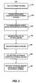
- FIG. 3illustrates a flow diagram of a method of tracking electronic devices according to another embodiment of the present invention.
- an automatic tracking system and methodfor tracking the presence and/or location of any tagged electronic device within a data center.
- the purpose of automatically tracking electronic devicesis to continuously monitor the location of each and every tagged electronic device down to the specific aisle, rack, and bay where the electronic device is mounted.
- a rack apparatusin which identification technology “overlays” the rack apparatus wherein the identification technology is provided to track the presence and location of electronic devices located within the rack.
- identification technologymeans any system or apparatus for identifying objects such as bar code systems, magnetic stripe systems, radio frequency identification (RFID or RF identification) systems, and the like.
- rack apparatusis synonymous with data rack, server rack, electronics housing or enclosure, and the like.
- the present inventionis not limited only to server rack applications implementing RF technology.
- RF systemstypically include readers and one or more tags that are attached to respective objects whose identity is thereby tracked.
- Readersare synonymous with interrogators, exciters, transceivers, transmitter/receivers, and the like.
- Tagsare synonymous with transponders, and the like.
- the tagis an electronic device that incorporates unique identification data, such as a number, and is generally attached to an object whose identity is desired to be tracked. Thus, the object's identity is identified by the interrogating reader which reads the number of the tag to which the object is attached.
- the RF systemoperates on radio frequency and, thus, RF systems do not require a direct line of sight between the reader and the tag. As such, the tag and tagged object may be located within an enclosure.
- RF tagsare also known as RF transponders and may be “active” or “passive”. Active tags are continuously powered by a battery, whereas passive tags briefly acquire power from the reader upon being interrogated thereby.
- Passive tagstypically include a coil or antenna to collect the from the reader the RF signal from which the tag derives its temporary operating power. Accordingly, passive tags are located within close proximity to the reader (typically in the range of a few centimeters up to one meter) in order to ensure that the tags collect a sufficient amount of energy to operate. Passive tags typically include an integrated circuit for storing data an identification number. Passive tags are typically desirable due to their smaller size, fewer components, and reduced cost compared to active tags.
- the readertypically includes an antenna, analog circuitry, digital processing circuitry, and a memory.
- the analog circuitryincludes modulation circuitry for transmitting and receiving signals to and from the tag.
- the digital processing circuitrygenerates an interrogation signal which is modulated using the analog circuitry.
- the readeremits a radio frequency signal in the vicinity of the tag and the tag emits a response, from which the RF system determines the identity of the responding tag.
- the readertransmits a coded RF signal, from which a nearby tag or tags collect energy.
- the nearby taguses the collected energy to compare the coded RF signal to the tag's identification data. If the tag's identification data is the same as that encoded in the RF signal, then the tag relays its encoded identification data back to the reader.
- the RF systemis configured to use the reader to interrogate the tag and then automatically relay the tag's identification data back through the RF system to the reader.
- an enclosure or rack 10which may be, for example, an Electronics Industry Association enclosure, 78 in. (2 meters) wide, 24 in. (0.61 meter) wide and 30 in. (0.76 meter) deep.
- the rack 10includes opposed pairs of mounts 12 that define open bays 14 a - n into which electronic devices 16 are located.
- the term “rack”includes any doors, lids, or other accessories associated with the rack (not shown).
- mounts 12 and bays 14 a - nmerely exemplify one of any number of mounting means that are used with rack apparatus.
- the term “bay”is synonymous with slot, opening, location, position, and the like. It is contemplated that a single, particularly large, electronic device could occupy multiple bay locations within the rack 10 .
- the rack 10may house any number of electronic devices 16 which may be modules, server boards, telecommunications devices, and the like, e.g., about forty (40) to eighty (80) devices.
- the electronic devices 16typically include a number of components 18 , e.g., processors, micro-controllers, high speed video cards, memories, semi-conductor devices, and the like.
- Some racksinclude retractable rails to which the electronic devices are slidably mounted, wherein the retractable rails permit the electronic devices to be moved between a retracted position within the rack and an extended position in which the electronic devices are at least partially extended from the rack. In any case, it is highly desirable to track the presence, identification, and/or location of each electronic device 16 within each rack 10 in a data center.
- each electronic device 16is tagged with a tracking device or tag 20 , such as a radio frequency (RF) transponder, or RF tag, as shown.
- the tag 20may instead be a bar code tag, a magnetic tag, magneto-mechanical tag, microwave tag, and the like.
- RF tagsare typically programmed with unique identification codes that identify an object with which the RF tags are associated.
- the tag 20may be a passive device. In another embodiment, the tag 20 may be an active device having a relatively greater communication range.
- the terminology “tracking device” or “tag”means hardware, information, signals, and the like that are not necessarily intrinsic to the circuitry or software associated with the electronic devices 16 or components 18 thereof.
- the tag 20is externally or extrinsically attached to a respective electronic device and is independent of the internal or intrinsic workings of the electronic devices 16 and components 18 .
- the tag 20may be encoded with any unique identification, such as medium access controlled identification of the electronic device with which it is associated.
- each electronic device 16Before each electronic device 16 is installed in the rack 10 , it is “tagged” with respective RF tags 20 .
- the word “attached”is broadly construed to include all types of associating an RF tag with an object to be tagged.
- the tags 20are shown mounted onto a left front portion of each electronic device 16 , but the tag 20 can be mounted to, printed on, or encapsulated within each electronic device 16 .
- the tag 20may be attached to the respective electronic device by adhesive, double-sided tape, metal fasteners, and the like. Care is taken to ensure that the tags 20 are attached at a uniform location on the face of each corresponding electronic device 16 so that each tag 20 aligns with the path of the reader 22 .
- each tag 20is in close proximity to the path of the reader 22 , as will be discussed further below.
- Those skilled in the artwill recognize that many other methods of physically associating tags 20 with respective electronic devices 16 are possible and the present invention is not limited to the examples set forth herein. In other words, it is not necessary to mount the tag 20 exactly as shown and it is contemplated that the tag 20 can be located anywhere on or in the electronic device 16 , so long as the tag is within the recommended operating range of the manufacturer.
- a traversable reading device or reader 22is shown in a first reading position (in solid) and in a second reading position (in phantom) in FIG. 1 .
- the reader 22is provided for traversing along each bay 14 a - n and tracking device 20 to read the tracking devices 20 that are present in the rack 10 .
- the reader 22may be an RF transponder, bar code scanner, magnetic pickup, and the like.
- the reader 22is rendered traversable by a traversing mechanism 24 that is mounted to a front face 26 of the rack 10 .
- the reader 22 and traversing mechanism 24could be mounted to other areas of the rack 10 , such as an inside wall or an access door (not shown).
- the traversing mechanism 24is a powered screw servo-system, which are generally known to those of ordinary skill in the art.
- the traversing mechanismmay be any device for providing and tracking linear motion such as a belt trolley, a pneumatic or hydraulic piston system, a linear motor system, and the like.
- the present inventionis not limited to any one specific type of traversing mechanism 24 .
- the traversing mechanismmay be mounted to the rack 10 in any reasonable manner including any of a variety of fastening devices.
- the traversing mechanism 24could alternatively be mounted to other locations of the rack including the back, the sides, a door (not shown), and the like.
- the traversing mechanismis mounted to ensure that reader 22 traverses a path proximate the tags 20 so as to function within their predetermined operating envelope.
- Typical operating ranges between readers 22 and passive tagsare usually within about 18 inches. In practice, this range will vary depending on the output power of the reader, the geometries of the reader and tags, the signal frequency, and other operating parameters.
- the traversing mechanism 24is a powered screw servo-system, which are generally known in the art.
- the traversing mechanism 24thus basically includes a motor 28 , a threaded rod 30 that is rotated by the motor 28 , and a threaded collar 32 that is linked to the threaded rod 30 .
- the powered screw deviceconverts rotation of the motor 28 into longitudinal translation of the threaded collar 32 and reader 22 .
- the reader 22is mounted to the threaded collar 32 in any reasonable manner including brackets and fasteners, tie straps, adhesive, and the like. Accordingly, the reader 22 is translatable or traversable along the length of the threaded rod 30 .
- a position sensor or encoder 34is attached to or integrated with the motor 28 to sense the angular position of the threaded rod 30 from which the relative longitudinal position of the threaded collar 32 and reader 22 can be determined.
- position sensorsencompasses a wide range of sensors, switches and technologies that are used to determine the placement, speed or movement, direction, and location of a given target. More specifically, linear position devices include cable extension, capacitive, eddy current, fiber optic, Hall effect, inductive, magneto resistive, optical triangulation, photoelectric, position displacement, ultrasonic, and variable resistance technology sensors. Other linear position devices include laser micrometers, linear potentiometers, LVDT's, and incremental encoders.
- an incremental encoderis typically used for linear position sensing.
- an incremental encoderWhen integrated into a control system, an incremental encoder provides motion and positioning feedback data to the system controller or processor. Incremental encoders are especially effective when used to digitally measure length or position by counting pulses of rotation that are related to a unit of length of travel.
- the longitudinal, or vertical, position of the readercan be fed back to and recorded by RF system memory.
- the location of each reader 22is initially associated with a respective rack and such location is recorded into RF system memory.
- the position of each reader 22 within its respective rackcan be continuously monitored with the position encoder 34 .
- a controller or processorcan “instruct” the motor 28 to drive the collar 32 and reader 34 to the top of the rack 10 whereby the collar 32 trips an internal or external “home” switch (not shown), as is known in the art. Accordingly, this action establishes the known “home” position of the reader 22 at bay 14 a .
- the reader 22can then interrogate bay location 14 a and thereby report the presence and location of any tag 20 and associated electronic device 16 in bay 14 a .
- the processorcan instruct the motor 28 drive the collar downward a known and predetermined distance to bay 14 b and repeat the interrogation.
- the collar 32 and reader 34can be directed in a known pattern to stop at known bay locations to interrogate the presence of a tag 20 and report its identity and location.
- the RF systemcan track such movement by virtue of the known location of the reader 22 and the position of the reader 22 within its respective rack, at any given time.
- FIG. 1further illustrates the reader 22 and the tags 20 according to an RF identification technology embodiment of the present invention.
- RFID systemsare generally known to those of ordinary skill in the art and are readily available from various manufacturers including Texas Instruments of Plano, Tex. and Alien Technologies of Morgan Hill, Calif. Also contemplated within the scope of the present invention are various other systems that use tags and reader to identify objects from a distance by associating the tag with the object, such as bar code systems.
- the tags 20store unique identification codes that identify the electronic devices 16 with which the tags 20 are associated and that can be read by the reader 22 .
- the tags 20may store the unique identification codes or data in addressable memory and may also store attributes of the corresponding electronic device 16 .
- Each of the tags 20includes a transceiver or an antenna 36 .
- the antennas 36e.g. coils or the like
- the tags 20receive an interrogation signal from the readers 22 from which the tags 20 convert to operating power.
- the term “proximate”means located or positioned within a distance wherein the tags 20 and reader 22 are operable with one another.
- the tags 20transmit a reply such as its identification code.
- the reader 22receives the identification code(s) from the tags 20 via an antenna 38 . In other words, the reader 22 interrogates each present tag 20 to receive the identification code therefrom.
- the reader 22when the reader 22 receives data, such as the identification code or attributes of the electronic devices, back from the tag 20 , it decodes that data and transmits the data to a tracking node 40 mounted atop the rack 10 .
- the tracking node 40includes a processor 42 and a transceiver 44 for communicating with other tracking nodes (not shown) and a host computer (not shown) elsewhere within the data center.
- the tracking node 40further includes volatile and non-volatile memory 46 and 48 respectively. Executable code for controlling activation of the reader 22 may be stored in the non-volatile memory 44 .
- the tracking node 40includes an interface 50 for communicating with the reader 22 and the position encoder 34 of the traversing mechanism 24 .
- the tracking node 40may be programmed to sequentially activate the reader 22 from top to bottom, vice-versa, or in any desired pattern since the position of the reader 22 is being monitored. It is also contemplated that the tracking node 40 could simultaneously activate the reader 22 if desired.
- the tracking node 40may query the status of any given bay 14 by activating the reader 22 to traverse the bays 14 and detect the presence or absence of tags 20 and their corresponding electronic devices 16 .
- the location of each reader 22is stored in the memory of the tracking node 40 , such as in the non-volatile memory 46 or a separate storage device (not shown).
- the tracking node 40can correlate the monitored location of the reader 22 to a corresponding tag 20 and associated electronic device 16 . Accordingly, the tracking node 40 can detect not only the presence of any given electronic device 16 within a bay 14 , but can also determine the location of a particular electronic device 16 by its identification code of its tag 20 .
- FIG. 3illustrates a method 300 for determining the presence and location of electronic devices within a rack, according to an embodiment of the invention.
- Steps 310 - 340involve the initial setup of electronic devices within racks in a data center.
- the electronic devicesare tagged, such as with an RF tag as described above.
- designated locationsare provided for receiving each of the electronic devices, such as bays within a server rack as discussed above.
- a reading devicesuch an RF reader is traversed along the designated locations for the electronic devices.
- the position of the reading deviceis monitored by an encoder feedback arrangement as discussed above.
- Steps 350 - 370involve operation of the RF system according to an embodiment of the present invention.
- the reading deviceis activated by the RF system to interrogate or read the tagged electronic devices.
- the identification of each present tagged electronic deviceis collected.
- the RF readermay collect the identification of each present tagged electronic device in sequence, such as starting from a home position at the top of the rack and ending in a distal position at the bottom of the rack or vice versa.
- step 370based on the monitoring the position of the reading device and based on collecting the identification of each present tagged electronic device, the identification of each present tagged electronic device is associated with the position of the reader so as to determine the presence and location of present electronic devices.
- the method 300is an exemplary embodiment, and it will be apparent to one of ordinary skill in the art that the method is subject to many alternatives, modifications and variations without departing from the spirit and scope of the invention.
- the present inventionis capable of tracking the presence, identity, and/or location of electronic devices within racks in a data center.
- each rackis associated with a reader and each bay of each rack is traversable by the reader such that the RF system retains the reader location at any given time in memory.
- Electronic devicesare installed in the bays of the racks whereupon the reader traverses the bays and reads the tags associated with such electronic devices and the RF system associates the read tag data with the known reader location to, in turn, provide location information for each tagged electronic device.
- the RF systemcontinuously or intermittently monitors or activates the reader so that any change in location of an electronic device is automatically tracked.
- the present inventioneliminates the need for manual tracking or inventory of electronic devices.
Landscapes
- Engineering & Computer Science (AREA)
- Radar, Positioning & Navigation (AREA)
- Remote Sensing (AREA)
- Physics & Mathematics (AREA)
- General Physics & Mathematics (AREA)
- Theoretical Computer Science (AREA)
- Computer Networks & Wireless Communication (AREA)
- Radar Systems Or Details Thereof (AREA)
Abstract
Description
Claims (26)
Priority Applications (1)
| Application Number | Priority Date | Filing Date | Title |
|---|---|---|---|
| US10/383,652US7350715B2 (en) | 2003-03-10 | 2003-03-10 | Tracking electronic devices |
Applications Claiming Priority (1)
| Application Number | Priority Date | Filing Date | Title |
|---|---|---|---|
| US10/383,652US7350715B2 (en) | 2003-03-10 | 2003-03-10 | Tracking electronic devices |
Publications (2)
| Publication Number | Publication Date |
|---|---|
| US20040178269A1 US20040178269A1 (en) | 2004-09-16 |
| US7350715B2true US7350715B2 (en) | 2008-04-01 |
Family
ID=32961309
Family Applications (1)
| Application Number | Title | Priority Date | Filing Date |
|---|---|---|---|
| US10/383,652Expired - LifetimeUS7350715B2 (en) | 2003-03-10 | 2003-03-10 | Tracking electronic devices |
Country Status (1)
| Country | Link |
|---|---|
| US (1) | US7350715B2 (en) |
Cited By (29)
| Publication number | Priority date | Publication date | Assignee | Title |
|---|---|---|---|---|
| US20060165039A1 (en)* | 2003-01-30 | 2006-07-27 | Geoff Lyon | RFID reader device having closely packed antennas |
| US20070252694A1 (en)* | 2006-04-28 | 2007-11-01 | Motorola, Inc. | Radio frequency identification tag based tray and tray receiving method and apparatus |
| US20070252709A1 (en)* | 2006-04-28 | 2007-11-01 | Motorola, Inc. | Radio frequency identification tag based task effectuation method and apparatus |
| US20080042839A1 (en)* | 2004-04-07 | 2008-02-21 | Matthias Grater | Device and Method for Identifying, Locating and Tracking Objects on Laboratory Equipment |
| US20090072967A1 (en)* | 2007-09-14 | 2009-03-19 | International Business Machines Corporation | Auto-locating system and method for data center mapping and monitoring |
| US20090247122A1 (en)* | 2008-04-01 | 2009-10-01 | William Fitzgerald | System for monitoring the unauthorized use of a device |
| US20090253410A1 (en)* | 2008-04-02 | 2009-10-08 | William Fitzgerald | Method for mitigating the unauthorized use of a device |
| US20090253406A1 (en)* | 2008-04-02 | 2009-10-08 | William Fitzgerald | System for mitigating the unauthorized use of a device |
| US20090282140A1 (en)* | 2008-05-09 | 2009-11-12 | Disney Enterprises, Inc. | Method and system for server location tracking |
| US7844702B1 (en)* | 2005-11-21 | 2010-11-30 | Oracle America, Inc. | Method and apparatus for physically locating a network component |
| US20110047188A1 (en)* | 2009-08-24 | 2011-02-24 | Carios Martins | Method and System for Automatic Tracking of Information Technology Components and Corresponding Power Outlets in a Data Center |
| US20110047263A1 (en)* | 2009-08-24 | 2011-02-24 | Carlos Martins | Method and System for Automatic Location Tracking of Information Technology Components in a Data Center |
| US20110169608A1 (en)* | 2009-11-13 | 2011-07-14 | Lafontaine Matthew R | Method of operating an rfid reader in an rfid system |
| US20110187503A1 (en)* | 2010-02-01 | 2011-08-04 | Mario Costa | Method and System for Data Center Rack Brackets For Automatic Location Tracking of Information Technology Components |
| US20110191454A1 (en)* | 2010-02-02 | 2011-08-04 | International Business Machines Corporation | Discovering physical server location by correlating external and internal server information |
| US20110193690A1 (en)* | 2007-09-03 | 2011-08-11 | Froehlich Paul | Method for identification of components in an electrical low-voltage switchgear assembly |
| US20110316690A1 (en)* | 2010-06-24 | 2011-12-29 | Siegman Craig S | System and Method for Identifying Electrical Equipment Using Wireless Receivers |
| US20140091138A1 (en)* | 2010-10-20 | 2014-04-03 | Panduit Corp. | RFID System |
| US8816857B2 (en) | 2010-10-20 | 2014-08-26 | Panduit Corp. | RFID system |
| US20140321362A1 (en)* | 2008-01-02 | 2014-10-30 | Bert Pipes | Automatic security alert system and method using mobile communication devices |
| US8932368B2 (en) | 2008-04-01 | 2015-01-13 | Yougetitback Limited | Method for monitoring the unauthorized use of a device |
| US9253308B2 (en) | 2008-08-12 | 2016-02-02 | Apogee Technology Consultants, Llc | Portable computing device with data encryption and destruction |
| US20160321896A1 (en)* | 2015-04-29 | 2016-11-03 | Digitalor Shenzhen Security Tech Inc. | Device for sampling and locating asset information and method for managing the same |
| US20170023502A1 (en)* | 2015-07-24 | 2017-01-26 | Schott Ag | High-precision method for determining thermal expansion |
| US9838877B2 (en) | 2008-04-02 | 2017-12-05 | Yougetitback Limited | Systems and methods for dynamically assessing and mitigating risk of an insured entity |
| US9886599B2 (en) | 2008-04-02 | 2018-02-06 | Yougetitback Limited | Display of information through auxiliary user interface |
| US9916481B2 (en) | 2008-04-02 | 2018-03-13 | Yougetitback Limited | Systems and methods for mitigating the unauthorized use of a device |
| US11439047B2 (en)* | 2019-10-30 | 2022-09-06 | International Business Machines Corporation | Server racks for hot aisle—cold aisle server rooms |
| US20250232695A1 (en)* | 2024-01-17 | 2025-07-17 | Dell Products L.P. | Active Information Tag for a Server Type Information Handling System |
Families Citing this family (22)
| Publication number | Priority date | Publication date | Assignee | Title |
|---|---|---|---|---|
| US7063256B2 (en) | 2003-03-04 | 2006-06-20 | United Parcel Service Of America | Item tracking and processing systems and methods |
| US7090134B2 (en) | 2003-03-04 | 2006-08-15 | United Parcel Service Of America, Inc. | System for projecting a handling instruction onto a moving item or parcel |
| US7561717B2 (en) | 2004-07-09 | 2009-07-14 | United Parcel Service Of America, Inc. | System and method for displaying item information |
| US20060273962A1 (en)* | 2005-06-02 | 2006-12-07 | Brench Colin E | Rack mounted directional antenna |
| US7726144B2 (en)* | 2005-10-25 | 2010-06-01 | Hewlett-Packard Development Company, L.P. | Thermal management using stored field replaceable unit thermal information |
| CN101802942A (en)* | 2007-01-29 | 2010-08-11 | 普迈公司 | Pinless power coupling |
| US20080272887A1 (en)* | 2007-05-01 | 2008-11-06 | International Business Machines Corporation | Rack Position Determination Using Active Acoustics |
| US8164453B2 (en)* | 2007-09-19 | 2012-04-24 | Chung Shan Institute Of Science And Technology, Armaments Bureau, M.N.D. | Physical audit system with radio frequency identification and method thereof |
| US7667855B2 (en) | 2008-02-29 | 2010-02-23 | International Business Machines Corporation | Providing position information to computing equipment installed in racks of a datacenter |
| AU2009307654A1 (en)* | 2008-10-20 | 2010-04-29 | Raritan Americas, Inc. | System and method for automatic determination of the physical location of data center equipment |
| US8077031B2 (en)* | 2009-08-20 | 2011-12-13 | Consortium P, Inc. | Position locating by polyhedral morphing |
| US8264354B2 (en)* | 2009-10-14 | 2012-09-11 | Attend Systems, Llc | Data center equipment location and monitoring system |
| US20110258302A1 (en)* | 2010-04-20 | 2011-10-20 | No Limits Software, LLC | System And Method For Remotely Determining Identification And Physical Location Of Equipment In A Rack |
| US20120166693A1 (en)* | 2010-07-26 | 2012-06-28 | Raritan Americas, Inc. | Intelligent Asset Management System |
| ES2625544T3 (en)* | 2012-01-26 | 2017-07-19 | Hanmi It Co., Ltd. | Scanner, scanning device and scanning method for a shelf |
| US9609466B2 (en)* | 2013-06-17 | 2017-03-28 | Hewlett Packard Enterprise Development Lp | Guide segment identification |
| US9224124B2 (en)* | 2013-10-29 | 2015-12-29 | Mobile Aspects, Inc. | Item storage and tracking cabinet and arrangement |
| US9269256B2 (en)* | 2013-12-17 | 2016-02-23 | Lenovo Enterprise Solutions (Singapore) Pte. Ltd. | Dynamic activation of service indicators based upon service personnel proximity |
| US11714975B2 (en) | 2014-10-28 | 2023-08-01 | Avery Dennison Retail Information Services Llc | High density read chambers for scanning and encoding RFID tagged items |
| IT201700027153A1 (en)* | 2017-03-13 | 2018-09-13 | Autoclima S P A | ACCOMMODATION UNIT AND STOCK MANAGEMENT |
| US10471478B2 (en) | 2017-04-28 | 2019-11-12 | United Parcel Service Of America, Inc. | Conveyor belt assembly for identifying an asset sort location and methods of utilizing the same |
| CN111601233B (en)* | 2019-02-21 | 2022-06-28 | 昆山纬绩资通有限公司 | Monitoring method and system for positioning device |
Citations (20)
| Publication number | Priority date | Publication date | Assignee | Title |
|---|---|---|---|---|
| US3864043A (en)* | 1972-11-01 | 1975-02-04 | Us Interior | Angular deviation measuring device and its method of use |
| US4636634A (en)* | 1984-08-28 | 1987-01-13 | Veeco Integrated Automation, Inc. | Apparatus with intelligent bins indicating the presence and identity of stored coded articles |
| US4839875A (en)* | 1986-05-19 | 1989-06-13 | Anritsu Corporation | Technique for automatic tracking of cassette rentals and managing of information related thereto |
| US4903815A (en)* | 1988-03-25 | 1990-02-27 | I.V.D.M. Ltd. | Automatic vending machine and system for dispensing articles |
| US5038023A (en)* | 1989-06-28 | 1991-08-06 | C. Itoh Information Systems Development, Inc. | System for storing and monitoring bar coded articles such as keys in a drawer |
| US5216618A (en)* | 1989-12-02 | 1993-06-01 | Sumitomo Rubber Industries, Ltd. | Method and apparatus for taking out and storing articles |
| US5303214A (en)* | 1992-01-03 | 1994-04-12 | International Business Machines Corporation | Multi-media-type automatic libraries |
| US5418732A (en)* | 1992-11-25 | 1995-05-23 | Odetics, Inc. | Laser targeting system |
| US5455409A (en)* | 1993-08-16 | 1995-10-03 | Texas Digital Systems, Inc. | Apparatus and method for monitoring a plurality of coded articles and for identifying the location of selected articles |
| US5583819A (en)* | 1995-01-27 | 1996-12-10 | Single Chip Holdings, Inc. | Apparatus and method of use of radiofrequency identification tags |
| US5771003A (en)* | 1996-09-24 | 1998-06-23 | Elenco Electronics, Inc. | Locating system and process |
| US5991759A (en) | 1997-03-25 | 1999-11-23 | Mci Communications Corporation | Method and system for defining equipment in a telecommunication network down to the rackface level |
| US6127928A (en) | 1998-02-10 | 2000-10-03 | E-Tag Systems, Inc. | Method and apparatus for locating and tracking documents and other objects |
| US6407933B1 (en) | 2000-10-18 | 2002-06-18 | Compaq Computer Corporation | Cable management system for use with rack mounted devices |
| US6448886B2 (en) | 1998-08-14 | 2002-09-10 | 3M Innovative Properties Company | Application for radio frequency identification systems |
| US6462670B1 (en) | 2000-10-18 | 2002-10-08 | Compaq Computer Corporation | Server system having front and rear identification |
| US6473762B1 (en) | 1997-03-25 | 2002-10-29 | Mci Communications Corporation | System and method to automatic equipment placement at remote sites |
| US6598789B1 (en)* | 1997-08-19 | 2003-07-29 | Canon Kabushiki Kaisha | Substrate managing system and substrate storing system |
| US6796506B1 (en)* | 2003-03-10 | 2004-09-28 | Hewlett-Packard Development Company, L.P. | Tracking electronic devices |
| US6946950B1 (en)* | 1999-07-12 | 2005-09-20 | Matsushita Electric Industrial Co., Ltd. | Mobile body discrimination apparatus for rapidly acquiring respective data sets transmitted through modulation of reflected radio waves by transponders which are within a communication region of an interrogator apparatus |
- 2003
- 2003-03-10USUS10/383,652patent/US7350715B2/ennot_activeExpired - Lifetime
Patent Citations (20)
| Publication number | Priority date | Publication date | Assignee | Title |
|---|---|---|---|---|
| US3864043A (en)* | 1972-11-01 | 1975-02-04 | Us Interior | Angular deviation measuring device and its method of use |
| US4636634A (en)* | 1984-08-28 | 1987-01-13 | Veeco Integrated Automation, Inc. | Apparatus with intelligent bins indicating the presence and identity of stored coded articles |
| US4839875A (en)* | 1986-05-19 | 1989-06-13 | Anritsu Corporation | Technique for automatic tracking of cassette rentals and managing of information related thereto |
| US4903815A (en)* | 1988-03-25 | 1990-02-27 | I.V.D.M. Ltd. | Automatic vending machine and system for dispensing articles |
| US5038023A (en)* | 1989-06-28 | 1991-08-06 | C. Itoh Information Systems Development, Inc. | System for storing and monitoring bar coded articles such as keys in a drawer |
| US5216618A (en)* | 1989-12-02 | 1993-06-01 | Sumitomo Rubber Industries, Ltd. | Method and apparatus for taking out and storing articles |
| US5303214A (en)* | 1992-01-03 | 1994-04-12 | International Business Machines Corporation | Multi-media-type automatic libraries |
| US5418732A (en)* | 1992-11-25 | 1995-05-23 | Odetics, Inc. | Laser targeting system |
| US5455409A (en)* | 1993-08-16 | 1995-10-03 | Texas Digital Systems, Inc. | Apparatus and method for monitoring a plurality of coded articles and for identifying the location of selected articles |
| US5583819A (en)* | 1995-01-27 | 1996-12-10 | Single Chip Holdings, Inc. | Apparatus and method of use of radiofrequency identification tags |
| US5771003A (en)* | 1996-09-24 | 1998-06-23 | Elenco Electronics, Inc. | Locating system and process |
| US5991759A (en) | 1997-03-25 | 1999-11-23 | Mci Communications Corporation | Method and system for defining equipment in a telecommunication network down to the rackface level |
| US6473762B1 (en) | 1997-03-25 | 2002-10-29 | Mci Communications Corporation | System and method to automatic equipment placement at remote sites |
| US6598789B1 (en)* | 1997-08-19 | 2003-07-29 | Canon Kabushiki Kaisha | Substrate managing system and substrate storing system |
| US6127928A (en) | 1998-02-10 | 2000-10-03 | E-Tag Systems, Inc. | Method and apparatus for locating and tracking documents and other objects |
| US6448886B2 (en) | 1998-08-14 | 2002-09-10 | 3M Innovative Properties Company | Application for radio frequency identification systems |
| US6946950B1 (en)* | 1999-07-12 | 2005-09-20 | Matsushita Electric Industrial Co., Ltd. | Mobile body discrimination apparatus for rapidly acquiring respective data sets transmitted through modulation of reflected radio waves by transponders which are within a communication region of an interrogator apparatus |
| US6407933B1 (en) | 2000-10-18 | 2002-06-18 | Compaq Computer Corporation | Cable management system for use with rack mounted devices |
| US6462670B1 (en) | 2000-10-18 | 2002-10-08 | Compaq Computer Corporation | Server system having front and rear identification |
| US6796506B1 (en)* | 2003-03-10 | 2004-09-28 | Hewlett-Packard Development Company, L.P. | Tracking electronic devices |
Cited By (54)
| Publication number | Priority date | Publication date | Assignee | Title |
|---|---|---|---|---|
| US20060165039A1 (en)* | 2003-01-30 | 2006-07-27 | Geoff Lyon | RFID reader device having closely packed antennas |
| US7686229B2 (en)* | 2003-01-30 | 2010-03-30 | Hewlett-Packard Development Company, L.P. | RFID reader device having closely packed antennas |
| US7746229B2 (en)* | 2004-04-07 | 2010-06-29 | Tecan Trading Ag | Device and method for identifying, locating and tracking objects on laboratory equipment |
| US20080042839A1 (en)* | 2004-04-07 | 2008-02-21 | Matthias Grater | Device and Method for Identifying, Locating and Tracking Objects on Laboratory Equipment |
| US7844702B1 (en)* | 2005-11-21 | 2010-11-30 | Oracle America, Inc. | Method and apparatus for physically locating a network component |
| US7528720B2 (en) | 2006-04-28 | 2009-05-05 | Motorola, Inc. | Radio frequency identification tag-based task effectuation method and apparatus |
| US7411502B2 (en)* | 2006-04-28 | 2008-08-12 | Motorola, Inc. | Radio frequency identification tag based tray and tray receiving method and apparatus |
| US20070252694A1 (en)* | 2006-04-28 | 2007-11-01 | Motorola, Inc. | Radio frequency identification tag based tray and tray receiving method and apparatus |
| US20070252709A1 (en)* | 2006-04-28 | 2007-11-01 | Motorola, Inc. | Radio frequency identification tag based task effectuation method and apparatus |
| US8917164B2 (en)* | 2007-09-03 | 2014-12-23 | Siemens Aktiengesellschaft | Method for identification of components in an electrical low-voltage switchgear assembly |
| US20110193690A1 (en)* | 2007-09-03 | 2011-08-11 | Froehlich Paul | Method for identification of components in an electrical low-voltage switchgear assembly |
| US20090072967A1 (en)* | 2007-09-14 | 2009-03-19 | International Business Machines Corporation | Auto-locating system and method for data center mapping and monitoring |
| US7642914B2 (en)* | 2007-09-14 | 2010-01-05 | International Business Machines Corporation | Auto-locating system and method for data center mapping and monitoring |
| US10536796B2 (en)* | 2008-01-02 | 2020-01-14 | Malcolm Wade Pipes | Automatic security alert system and method using mobile communication devices |
| US20140321362A1 (en)* | 2008-01-02 | 2014-10-30 | Bert Pipes | Automatic security alert system and method using mobile communication devices |
| US9881152B2 (en) | 2008-04-01 | 2018-01-30 | Yougetitback Limited | System for monitoring the unauthorized use of a device |
| US8932368B2 (en) | 2008-04-01 | 2015-01-13 | Yougetitback Limited | Method for monitoring the unauthorized use of a device |
| US20090247122A1 (en)* | 2008-04-01 | 2009-10-01 | William Fitzgerald | System for monitoring the unauthorized use of a device |
| US9576157B2 (en) | 2008-04-02 | 2017-02-21 | Yougetitback Limited | Method for mitigating the unauthorized use of a device |
| US9838877B2 (en) | 2008-04-02 | 2017-12-05 | Yougetitback Limited | Systems and methods for dynamically assessing and mitigating risk of an insured entity |
| US9886599B2 (en) | 2008-04-02 | 2018-02-06 | Yougetitback Limited | Display of information through auxiliary user interface |
| US20090253410A1 (en)* | 2008-04-02 | 2009-10-08 | William Fitzgerald | Method for mitigating the unauthorized use of a device |
| US9916481B2 (en) | 2008-04-02 | 2018-03-13 | Yougetitback Limited | Systems and methods for mitigating the unauthorized use of a device |
| US20090253406A1 (en)* | 2008-04-02 | 2009-10-08 | William Fitzgerald | System for mitigating the unauthorized use of a device |
| US20090282140A1 (en)* | 2008-05-09 | 2009-11-12 | Disney Enterprises, Inc. | Method and system for server location tracking |
| US9253308B2 (en) | 2008-08-12 | 2016-02-02 | Apogee Technology Consultants, Llc | Portable computing device with data encryption and destruction |
| US9679154B2 (en) | 2008-08-12 | 2017-06-13 | Apogee Technology Consultants, Llc | Tracking location of portable computing device |
| US9674651B2 (en) | 2008-08-12 | 2017-06-06 | Apogee Technology Consultants, Llc | Portable computing device with data encryption and destruction |
| US9686640B2 (en) | 2008-08-12 | 2017-06-20 | Apogee Technology Consultants, Llc | Telemetric tracking of a portable computing device |
| US9699604B2 (en) | 2008-08-12 | 2017-07-04 | Apogee Technology Consultants, Llc | Telemetric tracking of a portable computing device |
| US9392401B2 (en) | 2008-08-12 | 2016-07-12 | Apogee Technology Consultants, Llc | Portable computing device with data encryption and destruction |
| US9380416B2 (en) | 2008-08-12 | 2016-06-28 | Apogee Technology Consultants, Llc | Portable computing device with data encryption and destruction |
| US9369836B2 (en) | 2008-08-12 | 2016-06-14 | Apogee Technology Consultants, Llc | Portable computing device with data encryption and destruction |
| US20110047188A1 (en)* | 2009-08-24 | 2011-02-24 | Carios Martins | Method and System for Automatic Tracking of Information Technology Components and Corresponding Power Outlets in a Data Center |
| US20110047263A1 (en)* | 2009-08-24 | 2011-02-24 | Carlos Martins | Method and System for Automatic Location Tracking of Information Technology Components in a Data Center |
| US20110169608A1 (en)* | 2009-11-13 | 2011-07-14 | Lafontaine Matthew R | Method of operating an rfid reader in an rfid system |
| WO2011093937A3 (en)* | 2009-11-13 | 2011-09-22 | Solstice Medical, Inc. | Method of operating an rfid reader in an rfid system |
| US20110187503A1 (en)* | 2010-02-01 | 2011-08-04 | Mario Costa | Method and System for Data Center Rack Brackets For Automatic Location Tracking of Information Technology Components |
| WO2011094012A1 (en)* | 2010-02-01 | 2011-08-04 | Avocent Corporation | Data center rack brackets for tracking information technology components |
| US8271639B2 (en)* | 2010-02-02 | 2012-09-18 | International Business Machines Corporation | Discovering physical server location by correlating external and internal server information |
| US20110191454A1 (en)* | 2010-02-02 | 2011-08-04 | International Business Machines Corporation | Discovering physical server location by correlating external and internal server information |
| US8499067B2 (en)* | 2010-02-02 | 2013-07-30 | International Business Machines Corporation | Discovering physical server location by correlating external and internal server information |
| US8427301B2 (en)* | 2010-06-24 | 2013-04-23 | Avocent Corporation | System and method for identifying electrical equipment using wireless receivers |
| US20110316690A1 (en)* | 2010-06-24 | 2011-12-29 | Siegman Craig S | System and Method for Identifying Electrical Equipment Using Wireless Receivers |
| US9418256B2 (en)* | 2010-10-20 | 2016-08-16 | Panduit Corp. | RFID system |
| US9047581B2 (en) | 2010-10-20 | 2015-06-02 | Panduit Corp. | RFID system |
| US8816857B2 (en) | 2010-10-20 | 2014-08-26 | Panduit Corp. | RFID system |
| US20140091138A1 (en)* | 2010-10-20 | 2014-04-03 | Panduit Corp. | RFID System |
| US9633235B2 (en)* | 2015-04-29 | 2017-04-25 | Digitalor Shenzhen Security Tech Inc. | Device for sampling and locating asset information and method for managing the same |
| US20160321896A1 (en)* | 2015-04-29 | 2016-11-03 | Digitalor Shenzhen Security Tech Inc. | Device for sampling and locating asset information and method for managing the same |
| US20170023502A1 (en)* | 2015-07-24 | 2017-01-26 | Schott Ag | High-precision method for determining thermal expansion |
| US10942138B2 (en)* | 2015-07-24 | 2021-03-09 | Schott Ag | High-precision method for determining thermal expansion |
| US11439047B2 (en)* | 2019-10-30 | 2022-09-06 | International Business Machines Corporation | Server racks for hot aisle—cold aisle server rooms |
| US20250232695A1 (en)* | 2024-01-17 | 2025-07-17 | Dell Products L.P. | Active Information Tag for a Server Type Information Handling System |
Also Published As
| Publication number | Publication date |
|---|---|
| US20040178269A1 (en) | 2004-09-16 |
Similar Documents
| Publication | Publication Date | Title |
|---|---|---|
| US7350715B2 (en) | Tracking electronic devices | |
| US6796506B1 (en) | Tracking electronic devices | |
| US6600418B2 (en) | Object tracking and management system and method using radio-frequency identification tags | |
| EP1410353B1 (en) | Wireless identification method and tag | |
| CA1314610C (en) | Electromagnetic identification and location system | |
| US11763249B2 (en) | Robotic generation of a marker data mapping for use in inventorying processes | |
| EP2070001B1 (en) | Radio frequency identification system with doppler detector | |
| JP4286838B2 (en) | Information technology (IT) equipment positioning system | |
| EP0694860A2 (en) | Apparatus and method for identifying multiple transponders | |
| AU2001259116A1 (en) | Object tracking and management system and method using radio-frequency identification tags | |
| US20050116020A1 (en) | Locating individuals and games in a gaming establishment | |
| US20050246248A1 (en) | Mobile portal for radio frequency identification of objects | |
| US20070241901A1 (en) | System and method for object tracking via tag readings | |
| US20120229258A1 (en) | Proximity detection apparatus and method and asset management apparatus | |
| KR20110100648A (en) | Method and system for item level HF RDF tag with low frequency power assist | |
| CN114897117B (en) | An asset equipment positioning management system and method based on RFID | |
| US20230297952A1 (en) | Adaptive rfid inventory system | |
| EP3290948A1 (en) | Position detecting sensor and system | |
| EP3952118A1 (en) | Inventory tracking | |
| AU2023210199B2 (en) | Adaptive rfid inventory system | |
| CN205958960U (en) | Equipment control device | |
| JP7716044B2 (en) | Adaptive RFID Inventory System | |
| KR20060091836A (en) | Smart pad device for position recognition of moving object and its control method | |
| EP3545476A1 (en) | Robotic generation of a marker data mapping for use inventorying processes | |
| US12045684B2 (en) | System and method for inferring the presence of objects by means of identification and detection |
Legal Events
| Date | Code | Title | Description |
|---|---|---|---|
| AS | Assignment | Owner name:HEWLETT-PACKARD COMPANY, COLORADO Free format text:ASSIGNMENT OF ASSIGNORS INTEREST;ASSIGNORS:PRADHAN, SALIL V.;PATEL, CHANDRAKANT D.;LYON, GEOFF M.;REEL/FRAME:013674/0769;SIGNING DATES FROM 20030304 TO 20030306 | |
| AS | Assignment | Owner name:HEWLETT-PACKARD DEVELOPMENT COMPANY L.P., TEXAS Free format text:ASSIGNMENT OF ASSIGNORS INTEREST;ASSIGNOR:HEWLETT-PACKARD COMPANY;REEL/FRAME:014061/0492 Effective date:20030926 Owner name:HEWLETT-PACKARD DEVELOPMENT COMPANY L.P.,TEXAS Free format text:ASSIGNMENT OF ASSIGNORS INTEREST;ASSIGNOR:HEWLETT-PACKARD COMPANY;REEL/FRAME:014061/0492 Effective date:20030926 | |
| STCF | Information on status: patent grant | Free format text:PATENTED CASE | |
| CC | Certificate of correction | ||
| FPAY | Fee payment | Year of fee payment:4 | |
| FPAY | Fee payment | Year of fee payment:8 | |
| AS | Assignment | Owner name:HEWLETT PACKARD ENTERPRISE DEVELOPMENT LP, TEXAS Free format text:ASSIGNMENT OF ASSIGNORS INTEREST;ASSIGNOR:HEWLETT-PACKARD DEVELOPMENT COMPANY, L.P.;REEL/FRAME:037079/0001 Effective date:20151027 | |
| MAFP | Maintenance fee payment | Free format text:PAYMENT OF MAINTENANCE FEE, 12TH YEAR, LARGE ENTITY (ORIGINAL EVENT CODE: M1553); ENTITY STATUS OF PATENT OWNER: LARGE ENTITY Year of fee payment:12 |