US7349976B1 - Audio-on-demand communication system - Google Patents
Audio-on-demand communication systemDownload PDFInfo
- Publication number
- US7349976B1 US7349976B1US09/971,954US97195401AUS7349976B1US 7349976 B1US7349976 B1US 7349976B1US 97195401 AUS97195401 AUS 97195401AUS 7349976 B1US7349976 B1US 7349976B1
- Authority
- US
- United States
- Prior art keywords
- file
- audio
- data
- server
- subscriber
- Prior art date
- Legal status (The legal status is an assumption and is not a legal conclusion. Google has not performed a legal analysis and makes no representation as to the accuracy of the status listed.)
- Expired - Fee Related, expires
Links
Images


Classifications
- H—ELECTRICITY
- H04—ELECTRIC COMMUNICATION TECHNIQUE
- H04L—TRANSMISSION OF DIGITAL INFORMATION, e.g. TELEGRAPHIC COMMUNICATION
- H04L65/00—Network arrangements, protocols or services for supporting real-time applications in data packet communication
- H04L65/60—Network streaming of media packets
- H04L65/61—Network streaming of media packets for supporting one-way streaming services, e.g. Internet radio
- H04L65/612—Network streaming of media packets for supporting one-way streaming services, e.g. Internet radio for unicast
- H—ELECTRICITY
- H04—ELECTRIC COMMUNICATION TECHNIQUE
- H04L—TRANSMISSION OF DIGITAL INFORMATION, e.g. TELEGRAPHIC COMMUNICATION
- H04L65/00—Network arrangements, protocols or services for supporting real-time applications in data packet communication
- H04L65/60—Network streaming of media packets
- H04L65/70—Media network packetisation
Definitions
- the present inventionrelates to multimedia computer communication systems and, in particular, to communication systems which provide Audio-On-Demand services.
- multimedia capabilitiesare those associated with the transmission of audio information.
- a number of useshave been contemplated for transmission of audio information. For example, a user may want access to music or news, or may want to have a book read to them over their computer. Also, transmission of audio data provides much needed access to valuable information for visually impaired persons.
- Such multimedia communication systemswhich provide subscribers with selectable audio information are commonly called audio-on-demand systems.
- U.S. Pat. No. 5,132,992 issued to Yurt, et al.discloses an audio and video transmission and receiving system.
- the audio and video-on-demand system disclosed by Yurt, et al.distributes video and/or audio information to multiple subscriber units from a central source material library.
- Digital signal processingis used to compress data within the source material library so that such data can be transmitted over standard communication links such as a cable or satellite broadcast channel, or a standard telephone line to a receiver specified by subscriber service.
- the receiver subscriber unitincludes a decompressor for decompressing data sent from the source materials library and playing back the decompressed data by means of an audio or visual display.
- the present inventionprovides a real-time, audio-on-demand system which may be implemented using only the processing capabilities of the CPU within a conventional personal computer.
- a number of significant difficultiesarise when attempting to provide real-time audio-on-demand. It has been found that these difficulties are exacerbated when the subscriber receiving unit is a conventional personal computer having an Intel 486 microprocessor, or processors of equivalent power, as a central processing unit. Of course, higher power processors could be used, but such systems would become prohibitively expensive and would not be available to the mainstream personal computer user. In order to compensate for lack of processing power, special hardware or other additional capabilities would be needed.
- the system of the present inventionovercomes these difficulties so that real-time audio-on-demand is available to the average consumer on an unmodified personal computer.
- the system of the present inventionemploys an audio compression algorithm which provides audio compression on the order of 22:1.
- audio data in digitized formatrequires large amounts of memory space. It has been found that, in order to transmit digitized audio data so that a high quality audio signal is generated in real time, a data rate on the order of 22 kilobytes per second is typically necessary. However, current data rates achievable by most average cost modems on a reliable basis, fall in the range of 1.8 kilobytes (14.4 kilobits) per second.
- the real-time, audio-on-demand system of the present inventionprovides a form of audio compression which allows digitized audio data to be transmitted over a conventional 14.4 kilobits per second modem connection.
- Audio compression algorithmswhich may be used in accordance with the teachings of the present invention to provide audio compression on the order of 22:1 are well known in the art.
- the EIA/TIA IS-54 standardwhich is herein incorporated by reference, discloses an algorithm description such that one of ordinary skill in the art could implement a compression algorithm suitable for use in the present invention.
- a preferred embodiment of the algorithmemploys an adaptation of the IS-54 VSELP cellular compression algorithm compatible with the IS-54 VSELP cellular compression algorithm available from MOTOROLA.
- MOTOROLAcode excited linear predication
- Another preferred embodiment of the inventionutilizes the code excited linear predication (CELP) coder, version 3.2, available from NTIS, U.S.
- DRAMdynamic random access memory
- buffer memoriesare allocated within the DRAM to have on the order of approximately 16 or 32 kilobytes of storage. If digitized audio data is transmitted and received within the data buffer at too fast a rate, the buffers would overflow causing the loss of significant portions of data and audio dropout. As is well known in the art, audio dropout is a phenomena wherein audio playback terminates for some noticeable time period and then resumes after this delay. On the other hand, if data was transmitted too slowly, then the buffers would empty out again resulting in significant dropout and degradation of audio quality.
- the present inventionprovides a method of monitoring and regulating the flow of data between the server and the subscriber unit which insures that the buffers are constantly maintained at or near maximum capacity.
- audio quality degradationmay be compensated for through the data flow regulation of the present invention.
- This flow regulationconstantly maintains the buffers at or near maximum capacity so that, in the event of a delay in the communication link, the subscriber unit can continue to play back audio already stored in the buffers until new audio data begins to arrive again.
- the present inventionemploys a method of transmitting high quality audio data compressed using a lossless compression algorithm or a compression algorithm having a compression ratio which requires transmission at a rate greater than real time, at selected intervals so that brief passages of higher quality audio signals are produced at playback.
- the usermay select when a high quality passage is to be sent so that important pieces of audio data are played back clearly.
- increased control over received audio datais provided for by transmitting selected significant portions of an audio clip being transmitted in anticipation that the user may desire to move immediately to a new position in the audio clip.
- the metadatamay include text, captions, still image data, high quality audio data, etc., and includes information so as to allow the subscriber to synchronize the metadata with significant events in the audio data.
- the metadatais correlated with the audio data to provide a combined audio and visual experience.
- the present inventionadvantageously provides dynamic allocation of server/subscriber pairs to insure the best possible quality of communication links between the server and the subscriber.
- FIG. 1shows a simplified schematic block diagram of an audio-on-demand system constructed in accordance with the present invention.
- FIG. 2Ais a more detailed schematic block diagram showing the main functional elements of the audio-on-demand system of the present invention.
- FIGS. 2B-2Dare schematic block diagrams showing the main functional elements of alternate embodiments of the net transports depicted in FIG. 2A .
- FIG. 3is a schematic block diagram showing the main functional elements of a receiving subscriber audio unit such as a subscriber personal computer.
- FIG. 5is a subcontrol flow diagram showing the general operation of the wave driver of FIG. 3 .
- FIG. 7depicts a control flow diagram which details the method employed within the read data subroutine block of FIG. 4B .
- FIG. 8Adepicts the various displays observed on the video screen of the subscriber personal computer as the user selects an audio clip to be played from a menu, and selects various options while the audio clip is being played.
- FIG. 8Bdepicts the various displays observed on the video screen of the subscriber personal computer as the user dials the server, logs into the server system, and initiates a disconnect.
- FIG. 9is a schematic representation of an exemplary data transaction between a server and a subscriber unit which illustrates method used in the high quality transmission mode of the present invention.
- FIG. 10is a simplified block diagram which depicts the main functional elements of an audio-on-demand system that provides real-time playback of audio data in addition to metadata which can be displayed in synchronism with corresponding audio data.
- FIG. 11is a simplified block diagram which depicts the main functional elements of an audio-on-demand system that provides audio playback of selected portions of high quality audio data in real-time.
- FIG. 12is a simplified block diagram which depicts the main functional elements of an audio-on-demand system that provides a table of contents indicating significant divisions within a requested audio clip, and which provides for immediate playback of audio data at the divisions specified in the table of contents.
- FIG. 13is a schematic representation of the method used in accordance with the present invention to manage the flow of data blocks from the server to the subscriber PC.
- FIG. 14illustrates the data structures of various data messages transmitted between the server and the subscriber PC in accordance with the teachings of the present invention.
- FIG. 1shows a simplified schematic block diagram of an “audio-on-demand” system constructed in accordance with the present invention.
- the system 100comprises a subscriber personal computer (PC) 110 (e.g., an IBM PC having a 486 Intel Microprocessor), having a video display 115 .
- the subscriber PC 110connects to an audio control center 120 over telephone lines 130 via a modem 140 .
- a usercalls the audio control center 120 by means of the modem 140 .
- the audio control center 120transmits a menu of possible selections over the telephone lines 130 to the personal computer 110 for display on the video display 115 .
- the usermay then select one of the available options displayed on the video display 115 of the computer 110 . For example, the user may opt to listen to a song or hear a book read.
- the modem 140disconnects from the audio control center 120 .
- FIGS. 2A-2D and FIG. 3are schematic block diagrams which show, in greater detail, the main functional elements of the audio-on-demand system 100 of the present invention which provides a real time audio-on-demand system in conjunction with the subscriber PC 110 which comprises a standard microprocessor based personal computer system.
- the term “standard” personal computer systemshould be understood to mean that the system includes a microprocessor of equivalent or greater processing power than an INTEL 486 microprocessor (although not necessarily compatible with an INTEL 486 microprocessor), a random access memory (RAM), an internal or external modem which transmits data in the approximate range of 9.6 Kbps to 14.4 Kbps, and some kind of sound card or sound chip which serves as a digital-to-analog converter.
- Such a systemis advantageously capable of running MICROSOFT WINDOWS software.
- a “standard” personal computer systemshould not be simply understood to be an IBM compatible computer.
- any kind of workstation or personal computing systeme.g., a SUN MICROSYSTEMS workstation, an APPLE computer, a laptop computer, etc.
- any kind of workstation or personal computing systeme.g., a SUN MICROSYSTEMS workstation, an APPLE computer, a laptop computer, etc.
- any kind of workstation or personal computing systeme.g., a SUN MICROSYSTEMS workstation, an APPLE computer, a laptop computer, etc.
- FIG. 2AA more detailed block diagram of the audio-on-demand system 100 of the present invention is depicted in FIG. 2A .
- the audio control center 120is shown in FIG. 2A to comprise a live audio source 210 and a recorded audio source 215 .
- the live audio sourcemay simply comprise a person talking into a microphone or some other source of live audio data like a baseball game, while the recorded audio source 215 may comprise a tape recorder, a compact disk, or any other source of recorded audio information.
- Both the live audio source 210 and the recorded audio source 215serve as inputs to an analog-to-digital converter 220 .
- the analog-to-digital converter 220may, in one embodiment, comprise a Roland7 RAP 10 analog-to-digital converter available with the Roland7 audio production card.
- the analog-to-digital converter 220provides inputs to a digital compressor 225 .
- a digital compressor 225compresses the digitized audio data provided by the analog-to-digital converter 220 in accordance with the IS-54 standard compression algorithm.
- the compressor 225provides inputs to a disk storage unit 230 , which in turn communicates with an archival storage unit 235 via a bidirectional communication link.
- the disk storage unit 230communicates with a primary server 240 , which may, in one embodiment, advantageously comprise a UNIX server class work station such as those produced by SUN Microsystems.
- the disk storage unit 230together with the archival storage unit 235 and the primary server 240 comprise an audio servicer 121 , as indicated by a dashed box.
- the audio control center 120may communicate bidirectionally with a plurality of subscriber PCs 110 or a plurality of proximate servers 260 via a net transport 250 .
- Each of the proximate servers 260communicate with temporary storage units 265 via a bidirectional communication link.
- each of the proximate servers 260communicate with subscriber PCs 110 via net transport communication links 270 .
- the analog-to-digital converter 220receives either live or recorded audio data from the live source 210 or the recorded source 215 , respectively.
- the analog-to-digital converter 220then converts the received audio data into digital format and inputs the digitized audio data into the compressor 225 .
- the compressor 225then compresses the received audio data with a compression ratio of approximately 22:1 in one embodiment in accordance with the specifications of the IS-54 compression algorithm.
- the compressed audio datais then passed from the compressor 225 to the disk storage unit 230 and, in turn, to the archival storage unit 235 .
- the disk storage unit 230together with the archival storage unit 235 , serve as audio libraries which can be accessed by the primary server 240 .
- the disk storage unit 230contains audio clips and other audio data which is expected to be referenced with high frequency, while the archival storage contains audio clips and other audio information which is expected to be referenced with lower frequency.
- the primary server 240may also dynamically allocate the audio information stored within the disk storage unit 230 , as well as the audio information stored within the archival storage unit 235 , based upon a statistical analysis of the requested audio clips and other audio information.
- the primary server 240responds to requests received by the multiple subscriber PCs 110 and the proximate servers 260 via the net transport 250 . The operation of the primary server 240 as well as the proximate servers 260 will be described in greater detail below with reference to FIGS. 6A and 6B .
- the proximate servers 260may be dynamically allocated to serve local subscriber PCs 110 based upon the geographic location of each of the subscribers accessing the audio-on-demand system 100 . This ensures that a higher quality connection can be made between the proximate server 260 and the subscriber PCs 110 via net transports 270 . Further, the temporary storage memory banks 265 of the proximate servers 260 are typically faster to access than the disk or archival storage 230 , 235 associated with the primary server 240 . Thus, the proximate servers 260 can typically provide faster access to requested audio clips.
- FIGS. 2B-2Ddepict various implementations of the net transport 250 , 270 .
- the net transport 250 , 270comprises a flow controller 272 , which communicates bidirectionally with an error correcting modem 274 .
- the error correcting modem 274communicates bidirectionally with an error correcting modem 278 via telephone lines 276 .
- the error correcting modem 278communicates with a flow controller 280 .
- the flow controllers 272 , 280are used to regulate the flow of data between the server ( 240 or 260 ) and the subscriber PC 110 .
- the flow controllers 272 , 280may be implemented as software provided within the server ( 240 or 260 ) and subscriber PC 110 .
- the embodiment of the net transport 250 shown in FIG. 2Bis typically used in applications where the flow of data is not automatically regulated in accordance with the parameters of the communication link.
- FIG. 2Cdepicts an alternative embodiment of the net transport 250 , 270 .
- the alternative embodimentcomprises a Transmission Control Protocol/Internet Protocol (TCP/IP) protocol 282 , which communicates bidirectionally with a modem 284 .
- TCP/IPTransmission Control Protocol/Internet Protocol
- the modem 284communicates bidirectionally with a modem 288 via telephone lines 286 .
- the modem 288communicates bidirectionally with a receiver and TCP/IP protocol 290 .
- the TCP/IP protocol 282 , 290is used to automatically regulate the flow of data between the server and the subscriber.
- the TCP/IP protocolmay be implemented as standard Chameleon software available from NETMANAGE, Inc.
- the embodiment of the net transport 270 depicted in FIG. 2Cis typically used in applications involving an INTERNET link or other communication link where the flow of data is automatically regulated.
- the net transport 270comprises a TCP/IP protocol 292 , which communicates bidirectionally with a high-speed network 294 .
- the high-speed networkin one embodiment, may comprise a T1 land line link or other fast transport communication link.
- the high-speed network 294communicates bidirectionally with a TCP/IP protocol 296 .
- the embodiment of the net transport 270 shown in FIG. 2Dis typically used in applications involving an internet link or other communication link where the flow of data is automatically regulated.
- FIG. 3is a schematic block diagram showing the main functional elements within the receiving personal computer 110 .
- the telephone line 130enters a receiver 300 which advantageously comprises an internal modem.
- the receiver 300connects to a CPU module 310 via a line 312 .
- the CPU module 310comprises a microprocessor such as an INTEL 486, as well as dynamic random access memory (DRAM) which may be allocated as buffer space.
- the CPU 310is shown to include a buffer memory 315 .
- the buffer memory 315may, in one embodiment, comprise a portion of the DRAM allocated at initialization of the audio-on-demand system 100 .
- the buffer 315 within the CPU 310connects to a decoder 320 via a line 322 .
- the decoder 320connects to a scratch buffer 326 (which advantageously comprises a portion of the DRAM associated with the CPU 310 ) via a line 324 .
- the scratch buffer 326connects to a wave driver 330 via a line 332 .
- the wave driver 330is advantageously implemented as software provided by sound card vendors or provided by the MICROSOFT WINDOWS operating system run by the CPU 310 .
- the wave driver 330also includes a buffer memory 335 which may comprise another portion of the DRAM allocated at initialization.
- the wave driver 330connects to a digital-to-analog converter (DAC) 338 via a line 337 .
- DACdigital-to-analog converter
- the DAC 338advantageously is found on a SOUNDBLASTER sound board available from Creative Labs.
- the DAC 338connects to an audio transducer 340 , which advantageously comprises a speaker, via a line 342 .
- the receiver 300receives the transmitted data signals from the line 130 and demodulates these signals into digital data.
- the digital datais provided as inputs to the buffer's memory 315 within the CPU 310 .
- the buffer 315outputs the digitized audio data to the decoder 320 for decompression.
- the decoder 320then passes the decompressed data to the scratch buffer 326 .
- the decompressed audio datais transmitted from the scratch buffer 326 to the buffer 335 of the wave driver 330 .
- the digital output of the wave driver 330is converted to analog by the DAC 338 .
- the DAC 338then outputs an electrical signal along the line 342 which causes the speaker 340 to produce audio.
- FIGS. 4A and 4Btogether depict a control flow diagram which describes the flow of control between the CPU 310 , the decoder 320 , the buffer 315 , and the wave driver 330 .
- the following description of the flow of control within the subscriber PC 110is not an exhaustive account of all of the signals and control functions associated with the operation of the subscriber PC 110 .
- a number of conventional operations and signals which relate to the flow of control within the subscriber PC 110 and which are not essential for understanding the teachings of the present inventionare not depicted in the flowchart of FIGS. 4A and 4B since these signals and operations are well known to those of ordinary skill in the art.
- FIG. 14depicts data structures for each of the messages used to communicate between the server 240 and the subscriber PC 110 .
- messages sent from the subscriber PC 110 to the serverinclude a REQUEST message 1400 , a BEGIN message 1402 , a PAUSE message 1404 , an EXTRAS OK message 1406 , an EXTRAS NO message 1408 , and a SEEK message 1410 .
- Each of the messagesinclude a one-byte identification field which indicates what type of message is being sent. Some of the messages include a further multiple-byte field containing other information.
- the REQUEST message 1400includes a one-byte identification field, a one-byte length field, and a multiple-byte name field, having the same number of bytes as indicated in the length field, for storing the name of the requested file.
- the SEEK message 1410includes a one-byte identification field and a four-byte time data field.
- the above described messageswill be described in greater detail with reference to the subscriber PC control flow diagram of FIGS. 4A and 4B , as well as FIG. 7 , below.
- Messages which are transmitted from the server to the subscriber PC 110include a TIME message 1420 , positive and negative ⁇ TIME messages 1425 , 1430 , an AUDIO DATA message 1435 , a SEEK ACKNOWLEDGE message 1440 , an STOP message 1445 , a LENGTH message 1450 , a SIZE message 1455 , and a TEXT message 1460 .
- Each of the messagesinclude a one-byte identification field which indicates what type of message is being sent. Some of the messages include a further multiple-byte field containing other information.
- the TIME message 1420includes a one-byte identification field and a four-byte time data field.
- the ⁇ TIME messages 1425 , 1430each include a one-byte identification field and a two-byte delta time field.
- the AUDIO DATA messageincludes a one-byte identification field, a one byte length field, and a multiple-byte data field, having the same number of bytes as indicated in the length field, and containing audio data.
- the LENGTH messageincludes a one-byte identification field and a four-byte time data field.
- the SIZE messageincludes a one-byte identification field as well as a four-byte time field, a one-byte rows field, and a one-byte columns field.
- the TEXT messageincludes a one-byte identification field as well as a four-byte time data field, a one-byte length field, and a variable length text data field.
- controlpasses to a decision block 401 which determines if any messages are pending within the PC 110 .
- the CPU 310In a typical WINDOWS environment, the CPU 310 must process and respond to a number of pending messages while also supporting the reception, control, and decompression of audio data when an audio clip is playing.
- the decision block 401insures that proper processing time is devoted to the currently running applications program. Thus, if the decision block 401 determines that a message is pending, control passes to an activity block 402 wherein the pending messages are sent to their designated addresses. The process then re-enters the decision block 401 .
- the usertypically selects the audio clip from a menu of audio clips displayed on the video display terminal 115 of the subscriber PC 110 .
- FIG. 8Adepicts a video display such as a user might observe when selecting an audio clip from a menu 800 of audio clips in accordance with the teachings of the present invention. To select the clip from the menu 800 , the user simply directs the mouse pointer over the title of the desired audio clip on the menu and clicks the mouse button once.
- the usermay opt to type in the name of an audio clip which the user wishes to be played.
- the subscriber PC 110transmits a request message to the server 240 which indicates the name of the clip which is to be played.
- the request messagemay also include an address at which the requested audio clip may be located within the server memory bank 230 (see FIG. 2 ). This operation is represented within the activity block 404 .
- the server 240accesses the requested clip upon reception of the request message from the subscriber PC 110 .
- the subscriber PC 110determines whether or not the user has indicated that the selected audio clip is to be played. If the subscriber PC 110 determines that the user has indicated that the clip is to be played (e.g., by clicking the appropriate mouse button on a “play” field 810 shown in FIG. 8A ), then control passes to an activity block 410 , wherein a begin message is sent to the server 240 . If the user has not yet indicated that the selected audio clip is to be played, then control instead passes to a delay loop including a decision block 408 . The decision block 408 determines whether or not the user has ended the connection while the subscriber PC 110 is waiting for the user to indicate that the selected clip is to be played.
- the userneed not initiate playing of the audio clip. Rather, the begin signal is simply transmitted automatically (i.e., control passes directly from the activity block 404 to the activity block 410 ).
- the server 240upon reception of a begin signal from the subscriber PC 110 , the server 240 initiates data transmission of the requested audio clip to the subscriber PC 110 .
- the subscriber PC 110determines if the user has initiated a seek operation. As illustrated in FIG. 8A , the user may wish at any time within the playing of an audio clip to seek a particular location within the clip and begin playing the clip immediately from that location. It should be made clear here that the time elapsed within an audio clip is typically referred to as the “location” within the audio clip. To seek a particular location within the clip and begin playing the clip immediately from that location, the user need only place the mouse arrow over a box 850 within a play time bar 840 and click and hold.
- the userthen moves the box 850 to another location along the play time bar 840 according to the commonly used “click and drag” method and releases the mouse button to release the box 850 and continue playing the audio clip from the time indicated by the play time bar 840 .
- the same operationmay be performed by clicking and holding the mouse button down while the mouse pointer is over rewind or fast forward fields 860 , 870 , respectively.
- the seek operationmay also be accomplished by other methods as well.
- controlpasses to an activity block 414 , wherein a seek signal is sent to the server 240 .
- the server 240when the server 240 receives a seek message from the subscriber PC 110 , the server 240 locates the position in the audio clip which is sought by the user and begins retransmitting from that position (Of course, it should be understood that the server 240 never interrupts transmission in the middle of an audio block, but rather interrupts transmission once the full block has been transmitted, in order to avoid protocol errors with the subscriber PC 110 ).
- the SEEK messageincludes a time stamp (a four-byte time field) which indicates the amount of time, in tenths of a second, by which the audio clip is to be advanced or rewound to the place in the audio clip sought by the user.
- Controlpasses from the activity block 414 to a subroutine block 416 , wherein the subscriber PC 110 flushes the buffers 315 and ignores all messages other than seek acknowledges from the server 240 until the server 240 has acknowledged each seek message not yet acknowledged.
- the subscriber PC 110also receives N blocks of new audio data within the buffer 315 before resuming playback to reduce the risk of dropout.
- the subscriber PC 110determines if there are any pending messages from the background applications program and attends to any of these messages to insure that the audio-on-demand system of the present invention does not inhibit the performance of the background applications program.
- Controlpasses from the subroutine block 416 to a decision block 418 wherein the subscriber PC 110 determines if the number of seek messages sent by the subscriber PC 110 is equal to the number of seek acknowledge signals received from the server 240 .
- the subscriber PC 110keeps track of the number of SEEK and seek acknowledge messages to prevent premature playback. Often, when a user indicates that the audio clip is to be played at a different place, the user may inadvertently select playback at several different places in the audio clip before the place which the user wants is actually found by the user. Thus, the subscriber PC 110 does not begin playback until an acknowledge message has been received for every seek message issued by the subscriber PC 110 .
- controlreturns to the decision block 412 . If it is determined within the decision block 412 that the user has not initiated a seek, then control passes immediately from the decision block 412 to a decision block 420 via a continuation point A.
- the subscriber PC 110determines if the user has initiated a pause. This can be done, for example, by clicking the mouse over a “pause” field 820 shown in FIG. 8A . Often times, the user will wish to pause the playing of the selected audio clip in order to attend to some other activity. Thus, the present invention allows the user to pause an audio clip in mid-stream and to resume playing the audio clip at the same point when the user indicates that the audio clip is no longer to be paused. If the subscriber PC 110 determines that the user has initiated a pause, then control passes from the decision block 420 to an activity block 421 , wherein a pause signal is sent to the server 240 .
- Controlpasses from the activity block 421 to a subroutine block 422 , wherein the buffers 315 are filled.
- the server 240discontinues transmission of audio blocks until a begin message is received. It should be understood that the server 240 never interrupts transmission in the middle of an audio block.
- Controlreturns to the decision block 405 (via a continuation point B) to determine if there are any pending messages, and from the decision block 405 to the decision block 407 to determine if the user has indicated that the audio clip is to resume playing. However, if it was determined within the decision block 420 that the user did not initiate a pause, then control passes immediately from the decision block 420 to the decision block 424 .
- the subscriber PC 110determines if the user has initiated a stop message. This may be accomplished by clicking the mouse button over a “stop” field 830 displayed on the video screen 115 as shown in FIG. 8A . If the user has initiated a stop message, then this indicates that the user wishes to discontinue playing the selected audio clip altogether. Consequently, control passes to an activity block 425 , wherein a stop signal is sent to the server 240 from the subscriber PC 110 . Control then passes from the activity block 425 to the decision block 401 ( FIG. 4A ) via a continuation point C. If it is determined within the decision block 424 , however, that the user has not initiated a stop message, then control passes instead to a decision block 426 .
- the subscriber PC 110determines if the user has initiated an end connection message. This means that the user intends to disconnect with the server 240 and request no further audio clips. It should be noted that the end connection message is typically sent by the WINDOWS application program in accordance with conventional methods. In response, control passes from the decision block 426 to an activity block 427 , wherein the subscriber PC 110 sends an end signal to the server 240 . Control then passes from the activity block 427 to the end block 409 ( FIG. 4A ) via a continuation point D. If it is determined by the subscriber PC 110 , however, that the user has not initiated an end connection message, control passes instead from the decision block 426 to a decision block 428 .
- the subscriber PC 110determines if there are any pending messages. If the subscriber PC 110 determines that there are messages pending, then control passes to an activity block 429 wherein the pending message is sent to the designated address. Control then returns to the decision block 428 until there are no further messages pending, at which time control passes from the decision block 428 to a decision block 435 .
- the subscriber PC 110determines if the buffers 315 are full. That is, if the buffers have enough room for the next series of data blocks to be transferred from the server 240 . If the buffers 315 are full, the subscriber PC 110 determines if there is memory storage space in the wave driver buffers 335 , as indicated within a decision block 437 . If there is no room in the wave driver buffer 335 , this indicates that further data output to the wave driver 330 would not be received within the buffers 335 . In response, in order that no data will be lost, control returns to the decision block 428 . However, if there is room within the buffers 335 of the wave driver 330 , then control passes to an activity block 439 .
- a block of compressed audio data within the buffer 315is decompressed by the decoder 320 and is passed to the scratch buffer 326 .
- controlpasses to an activity block 440 wherein the buffer 335 within the wave driver 330 is loaded with the decompressed audio data from the scratch buffer 326 .
- Controlthen returns to the decision block 428 wherein the subscriber PC 110 checks for pending messages, and from there control passes to the decision block 435 wherein another determination is made if the buffers 315 are full.
- a full block of compressed audio datais not present within the buffer 315 , then this indicates that no data can be decompressed from the buffers 315 and passed to the wave driver 330 .
- Controltherefore passes to an activity block 450 wherein a dropout flag is set to indicate the possibility of audio dropout. More specifically, the dropout flag may be used as a measure or indication of how well the transfer of audio data is being accomplished. A high frequency of dropout flags indicates that the audio data is not being transferred well while a low frequency of dropout flags indicates that audio data is being transferred smoothly.
- Controlpasses from the activity block 450 to the decision block 428 . However, if it is determined within the decision block 445 that a full block of compressed data is present within the buffer 315 , then this indicates that data is available to be decompressed and passed to the wave driver 330 via the buffer 326 . In response, control passes to the decision block 415 wherein a test is performed to determine if there is room within the wave driver buffers 335 , and the previously described method is followed.
- the audio-on-demand system 100 of the present inventionguards against dropout of audio data output from the speaker 340 . Such dropout could be observed if a series of erroneous data blocks were to be transmitted from the server 240 to the subscriber PC 110 and the buffer 315 was emptied so that no audio data would be passed on to the wave driver 330 or to the speaker 340 .
- each compressed block of audio datatakes up approximately 240 bytes of memory within the buffer 315 .
- the value of Nmay be chosen to optimize the performance of the system depending upon the specific application. For example, a slower computer may require a higher value of N to guard effectively against audio dropout than the value of N selected for a faster computer. It should also be understood that there are performance tradeoffs for selecting higher and lower values of N.
- FIG. 5details the operation of the wave driver 330 . It should be noted that the operation of the wave driver 330 depicted in FIG. 5 is substantially independent of the general control flow operation depicted in the flow chart of FIGS. 4A and 4B , so that the process described in accordance with the flowchart of FIG. 5 can be considered as running as a background process.
- the control flow for the wave driver 330initializes in a block 500 and passes to a decision block 510 . Within the decision block 510 , a determination is made if a block of decompressed audio data is being played by the wave driver 330 . If a block of decompressed audio data is being played by the wave driver 330 , then control passes to an activity block 520 wherein the remaining parts of the block which is being played are output to the speaker 340 . Control then returns to the decision block 510 .
- controlpasses to a decision block 530 wherein a determination is made if a block is present within the input buffer 335 of the wave driver 330 . If there is no block present within the input buffer 335 , then this indicates that no audio data will be played in the next cycle so that some degree of audio degradation or dropout will be observed at the output of the speaker 340 . Once control passes from the decision block 530 , control returns to the decision block 510 .
- FIGS. 6A and 6Bare control flow diagrams showing the general operation of the audio server 240 (or the proxy servers 260 ) shown in FIGS. 1 and 2 .
- the control flow diagramis represented in FIGS. 6A and 6B as operating in conjunction with a single server, one skilled in the art will appreciate that the audio server 240 advantageously operates in conjunction with multiple servers at once.
- the server 240comprises a SUN MICROSYSTEMS workstation
- the server 240is capable of operating in conjunction with as many as sixty servers at once. Control of the audio server 240 passes from a begin block 600 to a decision block 605 wherein the audio server 240 determines if the subscriber PC 110 has requested data.
- the server 240continues to monitor input lines from the subscriber PC 110 and to perform routine housekeeping activities until a data request is received from the subscriber PC 110 .
- controlpasses from the decision block 605 to a decision block 610 wherein a test is performed to determine if the subscriber PC 110 has requested the name of the audio clip to be transmitted. If the subscriber PC 110 has not requested the name of the audio clip to be transmitted, then the audio server 240 continues to monitor the input lines from the subscriber PC 110 until a name is requested.
- the name request sent by the subscriber PC 110may take the form of a data address of a memory location within the audio control center 120 , or simply a string of characters which serves to identify the audio data clip to be transmitted.
- initialization datais sent to the subscriber PC 110 .
- the initialization datamay advantageously include the name of the clip requested, a table of contents, and a LENGTH of clip message.
- the table of contentsmay include information about significant divisions within the data clip to be transmitted and the times at which these divisions occur.
- the LENGTH of clip messageindicates the length of the audio data clip in tenths of a second in one embodiment.
- the audio server 240determines if the server 240 has detected a stop marker at the end of the last transmitted block of compressed audio data.
- FIG. 13schematically depicts the method employed in accordance with the present invention to manage the flow of data from the server 240 to the subscriber PC 110 .
- the depiction of the audio server 240 and the subscriber PC 110 in FIG. 13is highly simplified in order to clearly depict the data flow management aspect of the present invention.
- An acknowledge marker 1300advantageously may be placed at the end of every 2 kilobyte block of data within an output memory queue 1310 of the audio server 240 , while a stop marker 1320 may be placed at the end of the intermediate 2 kilobyte blocks of data.
- one advantageous embodiment of the present inventionutilizes audio data blocks 1330 of approximately 240 bytes so that eight of these 240 byte data blocks combine to approximately fill a 2 kilobyte data block, as shown in FIG. 13 .
- the location and frequency of the acknowledge and stop markers 1300 , 1320is preferably selected based upon the processing speed of the subscriber PC 110 . Thus, PCs having higher processing speeds and generally are capable of receiving more blocks of data between stop and acknowledge markers.
- the acknowledge marker 1300indicates to the subscriber PC 110 that an acknowledge signal should be sent from the subscriber PC 110 to the server 240 .
- the stop marker 1320indicates to the server 240 that no further blocks of data are to be transmitted until the server receives an acknowledge signal from the subscriber PC 110 .
- controlpasses to a decision block 630 , wherein the server 240 determines if an acknowledge signal has been received from the subscriber PC 110 .
- controlpasses directly to a decision block 635 .
- the flow of data between the audio server 240 and the subscriber PC 110can be regulated so that the buffers 315 within the subscriber unit CPU 310 are maintained at near maximum capacity without overflowing.
- the CPU 310 within the subscriber unit 110constantly monitors the memory allocated within the buffer 315 within the decision block 435 . As data is read into the buffer 315 and acknowledge markers are detected by the receiving CPU 310 , the CPU 310 determines how much memory space is left within the buffer 315 .
- the subscriber PC 110transmits an acknowledge signal to the server 240 .
- the subscriber PC 110determines that there is sufficient room within the buffer 315 , then the subscriber PC 110 transmits the acknowledge signal to indicate to the server 240 that more data can be transmitted to the subscriber PC 110 .
- the acknowledge and stop markersregulate the flow of data from the server 240 to the subscriber PC 110 to insure that the buffers 315 within the subscriber unit CPU 310 are maintained at near maximum capacity without overflowing.
- the above described method of regulating the flow of data between the subscriber PC and the server 240may be implemented external to the server 240 and the subscriber PC 110 in flow controllers 272 , 280 as shown in FIG. 2B , or may simply be implemented within the server 240 and the subscriber PC 110 , as described above.
- server 240communicates with the subscriber unit 110 via a specialized communication link, such as TCP/IP, which provides data flow management services automatically, it is not necessary to employ the above-described method of regulating data flow from the server 240 to the subscriber PC 110 .
- the server 240determines within the decision block 630 that an acknowledge signal from the subscriber PC 110 has not been received, this indicates that the subscriber PC 110 has not yet successfully received and buffered the previously transmitted data block. In response, control returns to the decision block 630 wherein another test is performed to determine if an acknowledge signal has been received. Consequently, when the audio server 240 detects a stop marker, the server 240 will wait for an acknowledge signal from the subscriber PC 110 so that additional data blocks are not transmitted to the subscriber PC 110 until an acknowledge signal has been received from the subscriber PC 110 . Once the server 240 has received the acknowledge signal from the subscriber PC 110 indicating that the transmitted data block has been successfully buffered at the subscriber PC 110 , then control of the method passes to the decision block 635 .
- the audio server 240determines if the server 240 has received a seek signal from the subscriber PC 110 .
- the seek signalis transmitted by the subscriber PC 110 when the subscriber PC 110 intends to scan through the audio clip being transmitted by the server 240 and locate an audio portion on the clip. For instance, if the user is listening to the recording of a song and the user wishes to replay the last 10 seconds over again, the user inputs this information into the PC 110 .
- the subscriber PC 110then sends a seek message to the audio server 240 .
- the seek messageincludes a binary value, which represents, in tenths of seconds, the location in the audio clip being played to which the user wishes to advance or retreat.
- the seek acknowledge messageindicates to the subscriber PC 110 that the seek message has been received by the server 240 , so that the subscriber PC 110 can prepare to receive new data.
- Controlpasses from the activity block 640 to an activity block 645 wherein the audio control center 120 scans within the memory location containing the audio clip being transmitted and goes to an address at or near the time requested by the seek message. Control then passes from the activity block 645 to an activity block 650 via the continuation point B so that the audio data block at the location requested by the subscriber PC 110 is now transmitted to the subscriber PC 110 from the server 240 , as indicated within the activity block 650 .
- a testis performed to determine if the server 240 has received a pause message. If the server 240 has received a pause message from the subscriber PC 110 , this indicates that the user of the subscriber PC 110 wants to temporarily discontinue listening to the audio clip. Thus, in this case, the server 240 transmits enough data to fill up the buffers 315 of the subscriber unit CPU 310 , and then discontinues data transmission until a resume signal, which, in one embodiment, is identical to the begin signal transmitted within the activity block 411 , is received from the subscriber PC 110 .
- controlpasses from the decision block 655 to the decision block 625 . If, however, the server 240 has not received a pause message, control passes instead to a decision block 660 wherein a test is performed to determine if the server 240 has received a stop message. A stop message indicates that the user wishes to discontinue the particular audio clip being played. If the server 240 has received a stop message, then control passes from the decision block 660 to the decision block 605 . However, if the server 240 has not received a stop message, then control passes to decision block 670 via a continuation point A.
- the audio server 240determines if the server 240 has received an end message from the subscriber PC 110 .
- An end messageindicates that the subscriber PC 110 no longer wishes to access audio data from the audio control center 120 .
- controlpasses from the decision block 670 to an end block 675 when the server 240 receives an end message from the subscriber PC 110 .
- the time messageindicates the time elapsed within the audio clip being sent.
- a time stampis included with every data block so that it is not necessary to include the operations represented in the blocks 678 - 690 .
- FIG. 7depicts a control flow diagram which details the method employed within the read data subroutine block 444 of FIG. 4B .
- the subscriber PC 110determines what kind of data block is provided at the output of the receiver 300 ( FIG. 3 ).
- Controlpasses from a begin block 700 to a decision block 705 , wherein the subscriber PC 110 determines if the data block provided at the output of the receiver 300 contains audio data.
- an AUDIO DATA blocktypically includes a one-byte identifier field which indicates that the block is an AUDIO DATA block, a one-byte length field which indicates the length, in bytes, of the data field to follow, and a multiple-byte data field which contains digitized audio data.
- controlpasses to an activity block 710 , wherein the AUDIO DATA block is loaded into the buffer 315 .
- Controlthen passes to a return block 712 which passes the operation of the system back to the flow of control depicted within FIG. 4B (i.e., control returns to the decision block 443 in FIG. 4B ).
- controlpasses from the decision block 705 to a decision block 715 .
- the subscriber PC 110determines if the data available indicates the time elapsed within the audio clip being played. That is, if the data available at the output of the receiver 300 is a TIME data block.
- the TIME data blockcomprises four bytes of data indicating the time elapsed, in tenths of a second, within the currently played audio clip.
- controlpasses to an activity block 720 , wherein the time data contained within the TIME data block is indicated on the video display 115 of the subscriber PC 110 within a time elapsed field 890 ( FIG. 8A ).
- the server 240could simply transmit a three-byte ⁇ TIME message which indicates the time difference between the last time update and the current time. For example, assuming the time differences between updates is small, if the audio clip is at 1:01.6 (one minute, one and six tenths seconds) when the last time update arrives, and 0.3 seconds elapse between the last update and the current update, then a ⁇ TIME signal having a binary value corresponding to 0.3 seconds is sent to the subscriber PC 110 from the server. This requires fewer bits to transmit than a message indicating a binary value of 1:01.9, so that bandwidth may be saved by using ⁇ TIME messages rather than TIME messages. Control then passes from the activity block 720 to the return block 712 . However, if the subscriber PC 110 determines within the decision block 715 that the data block available at the output of the receiver 300 is not a TIME data block, control passes to a decision block 725 .
- the subscriber PC 110determines if the data block available at the output of the receiver 300 is a SEEK ACKNOWLEDGE block.
- the SEEK ACKNOWLEDGE blockis a one-byte acknowledge from the server 240 that the server 240 has received a seek message from the subscriber PC 110 . If the data block available at the output of the receiver 300 is a SEEK ACKNOWLEDGE block, control passes from the decision block 725 to a subroutine block 735 , wherein the buffers 315 are flushed. That is, the buffers 315 are emptied.
- the buffers 315are flushed by simply outputting the data contained within the buffers to the wave driver 330 and playing the remaining audio data over the speakers 340 . In another embodiment, the buffers 315 are emptied without playing the audio data contained within the buffers.
- Controlpasses from the subroutine block 735 to a decision block 740 , wherein the subscriber PC 110 waits for new data to arrive from the server 240 . If new data has not arrived, then control returns to the decision block 740 until new data arrives. Once new data arrives from the server 240 , control passes from the decision block 740 back to the decision block 705 . If it was determined within the decision block 725 that the data block available at the output of the receiver 300 is not a SEEK ACKNOWLEDGE data block, control passes from the decision block 725 to a decision block 730 .
- the subscriber PC 110determines if the data available at the output of the receiver 300 is a data block indicating the length of the audio clip to be transmitted (i.e., a LENGTH block), or a data block containing a table of contents (i.e., a TOC block) relating to the order of audio data within the audio clip to be sent.
- data blocks containing information relating to the length of the audio clip to be playedcomprise a four-byte data block indicating length in tenths of a second, while the data blocks containing information relating to a table of contents of the audio clip to be played comprise an multiple-byte data block which varies according to the size of the table of contents to be transmitted.
- the subscriber PC 110determines if the data block is an END data block. If the data block available at the output of the receiver 300 is an END data block, control passes from the decision block 750 to an end block 755 , wherein the subscriber PC 110 terminates the connection with the audio control center 120 . However, if no END data block is detected at the output of the receiver 300 , control passes to the return block 712 , and control returns to the method depicted in FIG. 4B .
- the present inventionIn addition to providing real time audio on demand using only the processing power available within a conventional personal computer system, such as an IBM PC having a 486 microprocessor, in accordance with the apparatus and method described above, the present invention also provides a number of other significant and advantageous features.
- the present inventionallows for transmission of higher quality data by intermixing audio data blocks having lossless compression (i.e., compression which results in substantially no loss of digital data) or compression which produces data which is sent in greater than real time, with audio data blocks compressed according to the IS-54 standard specified compression algorithm.
- the present inventionadvantageously contemplates providing an authoring tool which gives the user the ability to unify video and audio data.
- the system of the present inventionadvantageously provides a visually displayed outline of the audio data wherein visual data which relates to the audio data being played is displayed on the video display terminal 115 of the subscriber PC 110 .
- the useradvantageously may have instant access to any one of a number of significant divisions within the audio clip being played. For example, a user listening to a baseball game via the audio-on-demand system of the present invention may decide to advance to the bottom of the 9th inning from some other place within the baseball game audio clip.
- the audio-on-demand system of the present inventionmay advantageously dynamically allocate server/subscriber pairs based upon geographic proximity and quality of communication links so as to maximize the quality of the audio data transmitted from the server to the subscriber.
- FIG. 9illustrates one feature of the present invention wherein high quality audio data which is compressed according to a lossless compression algorithm is mixed with normal quality audio data which is compressed according to the compression algorithm specified within the IS-54 standard.
- the buffers 315may be loaded to a capacity such that it is safe to transmit short bursts of high quality audio at lower than real time. These bursts of data are advantageously transmitted in advance of the actual time in which they will be played to provide for high quality audio segments of significant length.
- the present inventionprovides for high quality playback of audio data by including a separate “high quality” buffer 1110 ( FIG. 11 ) within the DRAM of the subscriber PC 110 for holding high quality audio data.
- the usermay indicate which portions of the audio clip are to be designated as “high quality.”
- the high quality audio data corresponding to the designated portions of the audio clip to be playedis then sent in advance (e.g., during initial ramp-up, or when the buffer 315 is full) to the subscriber PC 110 where this data is stored in the separate “high quality” buffer 1110 .
- This datawould be accompanied by a time stamp indicating when it should be played.
- the high quality datais then decompressed at the time indicated by the time stamp to provide high quality playback of selected portions of the selected audio clip.
- the audio clipincludes predesignated portions of high quality audio data.
- This datais predesignated based upon the kind of data to be transmitted.
- musical jingles in a spoken narrationsuch as a commercial
- other musical data or sound effectse.g., recorded animal sounds and excerpts from actual speeches
- high compression audio algorithmssuch as that employed in accordance with the present invention to create normal quality compressed audio data, typically do not provide high quality reproduction for musical audio data.
- the predesignated high quality datais transmitted in advance so that a substantial portion (e.g., a twenty or thirty second clip) of audio data is stored in the high quality buffer 1110 .
- the high quality datais then played back at the times designated by the time stamp associated with each data block.
- the subscriber PC 110continuously monitors the status of the buffers 315 to determine if the buffers 315 typically remain at or near maximum capacity. If the subscriber PC 110 determines that the buffers 315 are at or near maximum capacity a high percentage of the time (e.g., advantageously 85%, while percentages in the range of 60% to 95% may be used as well, as called for by the specific application), then the subscriber PC 110 will send a high quality message (e.g., the EXTRAS OK message) to the audio control center 120 .
- the high quality messageindicates to the audio control center 120 that the audio control center 120 should transmit high quality data compressed according to a lossless compression algorithm.
- the high quality datawill be based upon the same audio source information as the normal quality data.
- normal quality datamay be transmitted instead as a substitute for the high quality data.
- the subscriber PC 110monitors the status of the buffers 315 . If the buffers 315 fall below a certain percentage of maximum capacity (e.g., 60% of maximum capacity), then the subscriber PC 110 sends a message to the audio control center 120 to discontinue transmission of the high quality data and instead supply the audio data compressed according to the IS-54 standard. In this manner, high quality data is transmitted in advance so that significantly long portions of high quality data may be assembled within the high quality buffer within the subscriber PC 110 .
- a certain percentage of maximum capacitye.g. 60% of maximum capacity
- an audio data bank 900contains audio data compressed according to the compression algorithm specified by the IS-54 standard, while another audio data memory bank 910 contains data compressed according to a lossless compression algorithm or a compression algorithm which requires transmission of audio data in greater than real time.
- the lossless compression algorithm used in accordance with the present inventionis the well known LEMPEL-ZIV audio compression algorithm.
- Such an audio compression algorithmhas a compression ratio of approximately 3:1.
- a switching system(which is advantageously implemented in software) including a switch controller 920 and a high speed switch 930 is provided which allows the audio control center 120 to switch alternately between the audio bank 900 and the audio bank 910 .
- each box of the buffers 315represents a memory storage location capable of holding, for example, one compressed block of normal quality audio data.
- Those boxes containing a “N”contain normal quality compressed audio data (i.e., data compressed according to the compression algorithm specified in the IS-45 standard), while data blocks containing an “H” contain high quality compressed audio data (i.e., data compressed according to a lossless compression algorithm).
- each high quality audio blockcorresponds to approximately the same audio playback time as one normal quality audio block but requires significantly more memory storage space.
- Each high quality audio storage blockis shown as taking up approximately eight times the memory storage taken up by each normal quality audio block.
- the subscriber PC 110determines that the buffers 315 are near maximum capacity (e.g., above 85% of capacity), this indicates that the normal quality data is being transferred in real time or greater than real time.
- the subscriber PC 100sends a “high quality” signal to the audio control center 120 to indicate that high quality data should be sent by the audio control center 120 .
- the switch controller 920 within the audio control center 120causes the switch 930 to connect the high quality data bank 910 to the output line 130 .
- the audio control center 120causes high quality data to be sent over the telephone line 130 to the subscriber PC 110 .
- an address pointeris constantly scanning addresses corresponding to identical audio data in both audio banks 900 , 910 .
- the audio data output by the high quality audio data bank 910will contain the same audio information as would have been provided by the normal quality audio data bank 900 .
- the high quality audio datatakes more time to transmit since more data is being transmitted at the same baud rate.
- the high quality datais represented as being in wider blocks which are spaced farther apart on the communication line 130 than are the normal quality data blocks.
- the high quality datais represented as being placed simultaneously on the line 130 , in practice, one or two blocks will typically be present on the line at a time while the other blocks represented are understood to be pending in a server output queue (not shown).
- the normal quality data still on the line 130is received by the buffers 315 , so that the buffers 315 remain at maximum capacity due to the high transmission rate of the normal quality data.
- This caseis depicted in the first (i.e., top) two stages of the time elapsed data transfer sequence of FIG. 9 .
- high quality data blocksare subsequently received by the high quality buffer 1110 .
- the middle three stages of the time elapsed data transfer sequence of FIG. 9depict high quality data blocks being read into the buffer 1110 .
- the high quality data blocksare read into the buffer 1110 in small bits (e.g., in 240 byte blocks) at a time.
- the high quality datais continuously being read into the buffer 1110 as the normal quality data blocks are evacuating.
- the high quality data blocksremain in the buffer 1110 until the designated time in the audio clip at which the high quality data blocks are to be played.
- the subscriber PC 110transmits a “normal quality” signal to the audio control center 120 to indicate that the audio control center 120 should discontinue transmitting data from the high quality audio bank 910 and resume transmitting data from the normal quality audio bank 900 .
- a “normal quality” signalto the audio control center 120 to indicate that the audio control center 120 should discontinue transmitting data from the high quality audio bank 910 and resume transmitting data from the normal quality audio bank 900 .
- the switch controller 920connects the normal quality audio data bank with the communication line 130 via the high speed switch 930 . All the while, an address pointer is constantly scanning addresses corresponding to identical audio data in both audio banks 900 , 910 .
- the audio data output by the normal quality audio data bank 900will contain the same audio information as would have been provided by the high quality audio data bank 910 .
- the buffer 315begins to refill and approach maximum capacity. This is depicted in the last three stages of the time elapsed data transfer sequence of FIG. 9 .
- the processis repeated so that high quality data can be periodically combined with normal quality data.
- an audio signal having small periods of higher quality playbackis provided using the above-described feature of the present invention so that a net overall improvement of sound quality results.
- Metadatais also transmitted in synchronism with the audio data.
- metadatashould be understood to mean extra or additional data beyond the already transmitted normal quality audio data (e.g., text, captions, still images, limited video, high quality audio data, etc.).
- a graphic displaymay be provided on the video display 115 of the subscriber PC 110 which depicts still images of people whose voices are played in the audio clip.
- a caption or other indiciamay be used to indicate which of the visually depicted speakers is currently speaking in the audio clip.
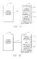
- FIG. 10is a simplified block diagram which depicts an audio-on-demand system 1000 which is specially adapted to transmit synchronized metadata with audio data.
- the system 1000is shown to include the audio control center 120 which is specially adapted to include an audio data file 1005 and a metadata file 1010 .
- the audio control center 120also includes the elements depicted in FIG. 2A .
- a switch controller 1020controls a high speed switching device 1030 which may, for example, comprise a multiplexer.
- the output of the switching device 1030connects to the receiver 300 within the subscriber PC 110 via the communication line 130 .
- the subscriber PC 110includes the elements depicted in FIG.
- the subscriber PC 110is specially adapted to include a high speed switch 1050 which connects to the output of the receiver 300 and which, in one embodiment, may comprise a demultiplexer.
- the switch 1050is controlled by a switch controller 1060 which may, for example, be implemented within the CPU 310 (not shown).
- the switching mechanism 1050connects alternatively to the audio buffers 315 , or to metadata buffers 1070 .
- the metadata buffers 1070may be allocated as a portion of the DRAM within the subscriber PC 110 .
- the audio control center 120transmits data to the subscriber PC according to the methods described above with reference to FIGS. 1-8 .
- the audio control center 120is able to transmit metadata such as text, captions, still images, a table of pertinent statistics, etc., which are synchronized with, and relate to, the transmitted audio data.
- metadatasuch as text, captions, still images, a table of pertinent statistics, etc.
- a graphical displaymay be shown (see the display 895 of FIG. 8A ) which indicates the current batter and other pertinent information such as the inning, the count and the score of the game.
- This datais displayed and updated in synchronism with the transmitted audio data so that the displayed metadata corresponds to the audio data which is currently being played back.
- Synchronization of the audio data and metadatais advantageously accomplished by time stamping the metadata to be activated at a corresponding time in the audio data transmission.
- Software running within the CPU 310advantageously correlates the time stamped metadata with the audio data being played back without requiring ancillary coprocessors.
- the audio-on-demand system 1000monitors the quality of the connection between the audio control center 120 and the subscriber PC 110 .
- the audio control center 120will begin to transmit interleaved audio and metadata blocks.
- the audio data blocksare provided by the audio data bank 1005 while the metadata blocks are provided by the metadata bank 1010 .
- the switch 1030alternately provided audio and metadata over the line 130 so that the audio blocks are interleaved with the metadata blocks in a ratio of, for example, two audio blocks for each metadata block (of course other ratios may be preferable depending upon the specific application and the quality of the connection between the audio control center and the subscriber PC 110 ).
- the subscriber PC 110receives the transmitted audio data and metadata and selectively stores the audio data within the audio data buffers 315 and the metadata within the metadata buffers 1070 .
- the switch controller 1060causes the switch 1050 to switch with the same timing as the switch 1030 .
- the subscriber PC 110may wait until the initial ramp-up is complete (i.e., until the audio data buffer 315 has stored at least N data blocks), and then immediately send an EXTRAS OK message to the audio control center 120 .
- the subscriber PC 110thereafter constantly monitors the audio buffers 315 . If the number of audio blocks in the buffers 315 is less than, for example, N/4 then the subscriber PC 110 sends an EXTRAS NO message to the audio control center 120 to indicate that only normal quality audio data and no metadata should be transmitted. When N blocks are again available within the buffer 315 , then EXTRAS OK is again transmitted.
- metadata which relates to a selected audio clipis transmitted to the subscriber PC 110 in advance of the time the metadata is actually to be displayed.
- metadata for an entire audio clipwill comprise a significantly smaller portion of the overall transmitted data than will the audio data for that clip.
- the metadata for an entire audio clipmay be transmitted, in interleave fashion with the audio data, in the first portion of the clip.
- the time stampindicates when the metadata is to be displayed during playback of an audio clip (e.g., a caption may be displayed at the 2 minute, 42 and 3 tenths second place in the audio clip).
- the row/column indicatordetermines where on the display screen 115 the metadata is to be presented (e.g., the caption may be displayed at the 312th pixel column and the 85th pixel row on the display screen 115 ).
- Metadatamay also be transmitted in advance at the occurrence of every seek.
- the audio control center 120transmits audio data from the point of the seek until the subscriber PC 110 sends an EXTRAS OK message (i.e., indicates that metadata is to be sent).
- the subscriber PC 110then transmits metadata, interleaved with the audio data, relating to audio to be played back after the point designated by the seek message.
- the metadataadvantageously includes a time stamp, it is routine for the server 240 to identify which metadata corresponds to audio data after the location designated by the seek message. In this manner, metadata can be provided without delay so that the metadata occurs substantially simultaneously with corresponding audio data.
- connections between proxy servers 260 and subscriber PCs 110may be dynamically allocated.
- local communication linkstypically provide higher quality connections for sustained periods than long distance communication links.
- dynamic allocation of server/subscriber pairsis used to provide improved quality communication links.
- a number of proxy servers 260( FIG. 2A ) are distributed throughout a geographic area.
- Each subscriber PC 110is provided with a map (which may be updated periodically) that indicates the locations of the local proxy servers 260 . Based upon the geographic location of the subscriber PC 110 , the subscriber PC 110 selects a server and establishes communication with that server for future transfers of audio data.
- the proxy server 260contacts a central server 240 .
- the proxy server 260begins transmitting data to the subscriber PC 110 for playback.
- the proxy server 260begins downloading audio data to the subscriber PC 110 even before the proxy server 260 has received the entire audio clip from the central server 240 .
- the audio control center 120may transmit advance data including a visually displayed table of contents.
- the table of contentsindicates significant divisions, or segments, within the requested audio clip (for example, chapters in a book, innings of a baseball game, movements in a sonata).
- the audio control center 120also transmits a small portion of audio data (e.g., one second worth of audio data) corresponding to the beginning of each division depicted in the table of contents.
- the table of contents and advance audio dataare then stored within a separate advance buffer 1210 as shown in FIG. 12 .
- the usermay simply click a mouse button while the mouse pointer is over the listing in the table of contents on the display screen 1115 .
- the subscriber PC 110immediately accesses the advance buffer 1210 to playback the audio data at the selected division.
- the subscriber PC 110sends a message to the audio control center 120 to transmit additional audio data corresponding to the remainder of the requested audio clip from the selected division.
- the audio-on-demand system of the present inventionprovides immediate playback of audio when the user selects playback at prespecified portions of the audio clip corresponding to significant divisions within the audio clip.
- the server 240could transmit a table of contents indicating the chapters of a book which is being read to a user at the subscriber PC 110 .
- the userwants to advance to another chapter, the user simply places the mouse pointer over the listed chapter and clicks the mouse button.
- the server 240receives this message and immediately begins transmitting data from the newly designated location at the beginning of the selected chapter.
- the subscriber PC 110begins playing back the stored audio segment corresponding to the selected chapter.
- the stored audio segment corresponding to the selected chapteris long enough to allow the buffer 315 to fill up the buffers with a predetermined number of blocks (e.g., the same number of blocks used to fill the buffers at initial ramp-up).
- the present inventionallows for immediate playback while also minimizing the risk of audio dropouts.
- the subscriber PC 110when a user at the subscriber PC 110 wishes to access audio data on demand, the user logs onto the subscriber PC 110 and selects an “audio-on-demand” option which appears on the video display screen 115 of the subscriber PC 110 . Once the user has selected the audio-on-demand option, the subscriber PC 110 initiates a connection with the central server 240 or one of the proxy servers 260 . In one preferred embodiment, the subscriber PC 110 may enter information corresponding to the current geographic location of the subscriber PC 110 . This feature would be highly advantageous for subscriber PCs implemented as laptop or palmtop computers when the subscriber is travelling. The subscriber PC includes a map indicating the geographic locations of available servers.
- the subscriber PC 110advantageously selects one of the available servers based upon the geographic proximity of the available servers to the subscriber PC 110 .
- the central server 240may assign a proxy server 260 to the subscriber PC 110 based upon the telephone number the subscriber PC 110 is calling from or information transmitted to the central server from the subscriber PC 110 regarding the subscriber PC's location.
- the server 240 , 260transmits a menu of audio data clips which may be accessed by the subscriber PC 110 .
- the subscriber PC 110may contain a prespecified menu of audio data.
- the menuis then displayed on the video screen 115 so that the user is advantageously able to scroll through the selections available on the menu list using a mouse pointer.
- the selectionscould include current radio broadcasts from selected cities, audio books, the audio from classic baseball games, music selections, and a number of other types of audio feeds.
- the userplaces the mouse pointer over the selection and clicks.
- the subscriber PC 110then issues a request message to the server 240 , 260 which includes a designation of the selected clip.
- the server 240 , 260accesses the requested audio clip within the memory of the server 240 , 260 . If the selected server is a proxy server 260 , and the proxy server 260 does not contain the requested clip in the temporary storage 265 , then the proxy server accesses the central server 240 to obtain the requested audio clip from the disk storage 230 or the archival storage 235 .
- the subscriber PC 110automatically transmits a begin message immediately after transmitting the request message to the server so that the server 240 , 260 immediately begins to transmit the audio clip to the subscriber PC 110 .
- the subscriber PC 110waits for the user to select a begin option by clicking the mouse pointer over a begin field on the display screen 115 .
- the serverwaits to receive the begin message to begin transmitting blocks of audio data to the subscriber PC 110 .
- the server 240 , 260typically transmits a block of information indicating how long (i.e., how many seconds) the audio clip is. This data is displayed on the screen 115 .
- the flow of data from the server 240 , 260 to the subscriber PC 110may be regulated by means of conventional regulation techniques employed in special communication links such as INTERNET which employs TCP/IP flow regulation.
- the data stream from the server 240 , 260 to the subscriber PC 110includes a plurality of interleaved stop and acknowledge markers.
- the acknowledge markersprecede the stop markers and are spaced at equal intervals from the stop markers.
- the server 240 , 260sends data out over the communication link 130 , the server determines if a stop marker is detected in the data stream. Once a stop marker is detected, the server 240 , 260 temporarily ceases the transmission of data to the subscriber PC 110 .
- the acknowledge and stop markersare spaced so that the subscriber PC 110 will ordinarily receive an acknowledge marker as the server is just about to detect the stop marker. Once the subscriber PC 110 detects the acknowledge marker, the subscriber PC 110 checks to see if it will have enough room in the memory to accept all the data between the next two stop markers. If so, the subscriber PC 110 generates an acknowledge signal and transmits the acknowledge signal back to the server 240 , 260 . Upon receiving the acknowledge signal, the server 240 , 260 continues the transmission of data until the next stop marker is detected. If the subscriber PC finds that it cannot accept the data between the next two stop signals then it will not send the acknowledge signal and the server will stop sending data at the stop signal. In an appropriate server/receiver transmission environment the stop and acknowledge markers could be located in the same position in the data stream and in fact could be a single identical marker.
- the subscriber PC 110decompresses the data and loads this data into the wave driver 330 for output to the DAC 338 .
- the DAC 338outputs the decompressed audio data to a speaker, or other audio transducer such as a hard plane, which plays back the audio data.
- a baseball gamecould be played back at the subscriber PC 110 .
- Additional datai.e., other than the audio data
- this additional dataincludes data which may be displayed on the video screen 115 such as the inning of the baseball game, the score, and the current batter.
- the audio data and the additional datais advantageously accompanied by time stamp information so that the additional data can be synchronously displayed with corresponding audio data.
- the useris presented with several options including an option to pause audio playback, an option to seek a new portion of the audio clip, an option to end transmission of the audio clip, etc.
- Each of these optionsmay be selected by the user by means of the mouse pointer.
- the selection of any optioncauses a corresponding message to be sent to the server 240 , 260 indicating the selected option.
- the server 240 , 260then responds in the appropriate manner.
- the usermay end the connection with the server 240 , 260 by activating a disconnect filed on the display screen 115 by means of the mouse pointer.
Landscapes
- Engineering & Computer Science (AREA)
- Multimedia (AREA)
- Computer Networks & Wireless Communication (AREA)
- Signal Processing (AREA)
- Information Transfer Between Computers (AREA)
Abstract
Description
Claims (24)
Priority Applications (1)
| Application Number | Priority Date | Filing Date | Title |
|---|---|---|---|
| US09/971,954US7349976B1 (en) | 1994-11-30 | 2001-10-04 | Audio-on-demand communication system |
Applications Claiming Priority (5)
| Application Number | Priority Date | Filing Date | Title |
|---|---|---|---|
| US08/347,582US5793980A (en) | 1994-11-30 | 1994-11-30 | Audio-on-demand communication system |
| US09/042,172US6151634A (en) | 1994-11-30 | 1998-03-13 | Audio-on-demand communication system |
| US09/237,099US6985932B1 (en) | 1994-11-30 | 1999-01-25 | Multimedia communications system and method for providing audio on demand to subscribers |
| US09/568,525US7464175B1 (en) | 1994-11-30 | 2000-05-09 | Audio-on demand communication system |
| US09/971,954US7349976B1 (en) | 1994-11-30 | 2001-10-04 | Audio-on-demand communication system |
Related Parent Applications (1)
| Application Number | Title | Priority Date | Filing Date |
|---|---|---|---|
| US09/568,525ContinuationUS7464175B1 (en) | 1994-11-30 | 2000-05-09 | Audio-on demand communication system |
Publications (1)
| Publication Number | Publication Date |
|---|---|
| US7349976B1true US7349976B1 (en) | 2008-03-25 |
Family
ID=39199329
Family Applications (1)
| Application Number | Title | Priority Date | Filing Date |
|---|---|---|---|
| US09/971,954Expired - Fee RelatedUS7349976B1 (en) | 1994-11-30 | 2001-10-04 | Audio-on-demand communication system |
Country Status (1)
| Country | Link |
|---|---|
| US (1) | US7349976B1 (en) |
Cited By (62)
| Publication number | Priority date | Publication date | Assignee | Title |
|---|---|---|---|---|
| US20050138660A1 (en)* | 1997-09-18 | 2005-06-23 | United Video Properties, Inc. | Electronic mail reminder for an internet television program guide |
| US20050165848A1 (en)* | 1999-04-13 | 2005-07-28 | Canon Kabushiki Kaisha | Data processing method and apparatus |
| US20050250439A1 (en)* | 2004-05-06 | 2005-11-10 | Garthen Leslie | Book radio system |
| US20050262257A1 (en)* | 2004-04-30 | 2005-11-24 | Major R D | Apparatus, system, and method for adaptive-rate shifting of streaming content |
| US20050258247A1 (en)* | 2002-02-12 | 2005-11-24 | Hawes Jonathan L | Associating media through steganography |
| US20050278768A1 (en)* | 1996-12-10 | 2005-12-15 | United Video Properties, Inc. | Internet television program guide system |
| US20060168119A1 (en)* | 1999-11-24 | 2006-07-27 | Kabushiki Kaisha Sega | Information processor, file server, accounting control system, accounting control method, and recording medium recording a program therefor |
| US20060195509A1 (en)* | 2005-02-09 | 2006-08-31 | Sony Corporation | Content reproduction system, content reproduction apparatus, and content reproduction method |
| US20070050479A1 (en)* | 2005-08-24 | 2007-03-01 | Sony Corporation | Content receiving apparatus and content receiving method |
| US20070185972A1 (en)* | 2006-02-08 | 2007-08-09 | Samsung Electronics Co., Ltd. | Method and device for managing content, storage medium; and adaptive content playing method using the same |
| US20080222235A1 (en)* | 2005-04-28 | 2008-09-11 | Hurst Mark B | System and method of minimizing network bandwidth retrieved from an external network |
| US20080293443A1 (en)* | 2004-03-19 | 2008-11-27 | Media Captioning Services | Live media subscription framework for mobile devices |
| US20090070833A1 (en)* | 1999-11-23 | 2009-03-12 | Gofigure, L.L.C.A Missouri Limited Liability Company | System and method for providing digital video to a wireless communications device |
| US20090144781A1 (en)* | 1994-11-30 | 2009-06-04 | Realnetworks, Inc. | Audio-on-demand communication system |
| US20100115541A1 (en)* | 1995-10-02 | 2010-05-06 | Starsight Telecast, Inc. | Interactive Computer System for Providing Television Schedule Information |
| US20100125591A1 (en)* | 2008-11-19 | 2010-05-20 | Yaakov Ben Tsvi | Merging files on storage and retrieve |
| US20100241430A1 (en)* | 2003-10-30 | 2010-09-23 | AT&T Intellectual Property II, L.P., via transfer from AT&T Corp. | System and method for using meta-data dependent language modeling for automatic speech recognition |
| US7818444B2 (en) | 2004-04-30 | 2010-10-19 | Move Networks, Inc. | Apparatus, system, and method for multi-bitrate content streaming |
| US20110035218A1 (en)* | 2004-03-19 | 2011-02-10 | Media Captioning Services | Live Media Captioning Subscription Framework for Mobile Devices |
| US20110231521A1 (en)* | 2010-03-22 | 2011-09-22 | Mobitv, Inc. | Media convergence platform |
| WO2013032402A1 (en)* | 2011-09-01 | 2013-03-07 | Mp4Sls Pte Ltd | Communication device and method for receiving media data |
| US8528032B2 (en) | 1998-07-14 | 2013-09-03 | United Video Properties, Inc. | Client-server based interactive television program guide system with remote server recording |
| US8578413B2 (en) | 1998-07-17 | 2013-11-05 | United Video Properties, Inc. | Interactive television program guide with remote access |
| US8683066B2 (en) | 2007-08-06 | 2014-03-25 | DISH Digital L.L.C. | Apparatus, system, and method for multi-bitrate content streaming |
| US8752085B1 (en) | 2012-02-14 | 2014-06-10 | Verizon Patent And Licensing Inc. | Advertisement insertion into media content for streaming |
| US8776125B2 (en) | 1996-05-03 | 2014-07-08 | Starsight Telecast Inc. | Method and system for displaying advertisements in an electronic program guide |
| US8832742B2 (en) | 2006-10-06 | 2014-09-09 | United Video Properties, Inc. | Systems and methods for acquiring, categorizing and delivering media in interactive media guidance applications |
| US8892495B2 (en) | 1991-12-23 | 2014-11-18 | Blanding Hovenweep, Llc | Adaptive pattern recognition based controller apparatus and method and human-interface therefore |
| US8904441B2 (en) | 2003-11-06 | 2014-12-02 | United Video Properties, Inc. | Systems and methods for providing program suggestions in an interactive television program guide |
| US9071872B2 (en) | 2003-01-30 | 2015-06-30 | Rovi Guides, Inc. | Interactive television systems with digital video recording and adjustable reminders |
| US9118958B2 (en) | 1999-12-10 | 2015-08-25 | Rovi Guides, Inc. | Systems and methods for coordinating interactive and passive advertisement and merchandising opportunities |
| US9125169B2 (en) | 2011-12-23 | 2015-09-01 | Rovi Guides, Inc. | Methods and systems for performing actions based on location-based rules |
| US9166714B2 (en) | 2009-09-11 | 2015-10-20 | Veveo, Inc. | Method of and system for presenting enriched video viewing analytics |
| US9191722B2 (en) | 1997-07-21 | 2015-11-17 | Rovi Guides, Inc. | System and method for modifying advertisement responsive to EPG information |
| US9197943B2 (en) | 1998-12-03 | 2015-11-24 | Rovi Guides, Inc. | Electronic program guide with related-program search feature |
| US20150346700A1 (en)* | 2014-06-02 | 2015-12-03 | Rovio Entertainment Ltd | Control of a computer program |
| US9288521B2 (en) | 2014-05-28 | 2016-03-15 | Rovi Guides, Inc. | Systems and methods for updating media asset data based on pause point in the media asset |
| US9294799B2 (en) | 2000-10-11 | 2016-03-22 | Rovi Guides, Inc. | Systems and methods for providing storage of data on servers in an on-demand media delivery system |
| US9319735B2 (en) | 1995-06-07 | 2016-04-19 | Rovi Guides, Inc. | Electronic television program guide schedule system and method with data feed access |
| US9326025B2 (en) | 2007-03-09 | 2016-04-26 | Rovi Technologies Corporation | Media content search results ranked by popularity |
| US9332051B2 (en) | 2012-10-11 | 2016-05-03 | Verizon Patent And Licensing Inc. | Media manifest file generation for adaptive streaming cost management |
| US9426509B2 (en) | 1998-08-21 | 2016-08-23 | Rovi Guides, Inc. | Client-server electronic program guide |
| US9535563B2 (en) | 1999-02-01 | 2017-01-03 | Blanding Hovenweep, Llc | Internet appliance system and method |
| US9578354B2 (en) | 2011-04-18 | 2017-02-21 | Verizon Patent And Licensing Inc. | Decoupled slicing and encoding of media content |
| US9609340B2 (en) | 2011-12-28 | 2017-03-28 | Verizon Patent And Licensing Inc. | Just-in-time (JIT) encoding for streaming media content |
| US10063934B2 (en) | 2008-11-25 | 2018-08-28 | Rovi Technologies Corporation | Reducing unicast session duration with restart TV |
| US20190204998A1 (en)* | 2017-12-29 | 2019-07-04 | Google Llc | Audio book positioning |
| US10992955B2 (en) | 2011-01-05 | 2021-04-27 | Divx, Llc | Systems and methods for performing adaptive bitrate streaming |
| US11012641B2 (en) | 2003-12-08 | 2021-05-18 | Divx, Llc | Multimedia distribution system for multimedia files with interleaved media chunks of varying types |
| US11017816B2 (en) | 2003-12-08 | 2021-05-25 | Divx, Llc | Multimedia distribution system |
| US11050808B2 (en) | 2007-01-05 | 2021-06-29 | Divx, Llc | Systems and methods for seeking within multimedia content during streaming playback |
| US11102553B2 (en) | 2009-12-04 | 2021-08-24 | Divx, Llc | Systems and methods for secure playback of encrypted elementary bitstreams |
| US11115450B2 (en) | 2011-08-31 | 2021-09-07 | Divx, Llc | Systems, methods, and media for playing back protected video content by using top level index file |
| US20210329124A1 (en)* | 2020-04-17 | 2021-10-21 | Marchex, Inc. | Systems and methods for rapid analysis of call audio data using a stream-processing platform |
| US11457054B2 (en) | 2011-08-30 | 2022-09-27 | Divx, Llc | Selection of resolutions for seamless resolution switching of multimedia content |
| US11495266B2 (en) | 2007-11-16 | 2022-11-08 | Divx, Llc | Systems and methods for playing back multimedia files incorporating reduced index structures |
| US11683542B2 (en) | 2011-09-01 | 2023-06-20 | Divx, Llc | Systems and methods for distributing content using a common set of encryption keys |
| US11711410B2 (en) | 2015-01-06 | 2023-07-25 | Divx, Llc | Systems and methods for encoding and sharing content between devices |
| US11785066B2 (en) | 2012-12-31 | 2023-10-10 | Divx, Llc | Systems, methods, and media for controlling delivery of content |
| US11886545B2 (en) | 2006-03-14 | 2024-01-30 | Divx, Llc | Federated digital rights management scheme including trusted systems |
| USRE49990E1 (en) | 2012-12-31 | 2024-05-28 | Divx, Llc | Use of objective quality measures of streamed content to reduce streaming bandwidth |
| US12407906B2 (en) | 2013-05-30 | 2025-09-02 | Divx, Llc | Network video streaming with trick play based on separate trick play files |
Citations (113)
| Publication number | Priority date | Publication date | Assignee | Title |
|---|---|---|---|---|
| US3882538A (en) | 1971-03-30 | 1975-05-06 | Edutron Inc | Multiple access message retrieval system |
| US3887763A (en) | 1972-07-19 | 1975-06-03 | Fujitsu Ltd | Video signal transmission system |
| US3990710A (en) | 1968-06-24 | 1976-11-09 | Hughes Robert M | Coin-operated recording machine |
| US4124773A (en) | 1976-11-26 | 1978-11-07 | Robin Elkins | Audio storage and distribution system |
| US4224644A (en)* | 1978-02-08 | 1980-09-23 | Videodetics Corporation | Method and apparatus for controlling a tape player/recorder for retrieving and playing prerecorded information |
| US4253157A (en) | 1978-09-29 | 1981-02-24 | Alpex Computer Corp. | Data access system wherein subscriber terminals gain access to a data bank by telephone lines |
| US4504705A (en) | 1982-01-18 | 1985-03-12 | Lgz Landis & Gyr Zug Ag | Receiving arrangements for audio frequency signals |
| US4506387A (en) | 1983-05-25 | 1985-03-19 | Walter Howard F | Programming-on-demand cable system and method |
| US4581484A (en) | 1982-09-29 | 1986-04-08 | Oclc Online Computer Library Center Incorporated | Audio-enhanced videotex system |
| US4611277A (en) | 1983-09-15 | 1986-09-09 | Bankamerica Corporation | Microcomputer communications software |
| US4658093A (en) | 1983-07-11 | 1987-04-14 | Hellman Martin E | Software distribution system |
| US4727422A (en) | 1985-06-03 | 1988-02-23 | Picturetel Corporation | Method and apparatus for efficiently communicating image sequence having improved motion compensation |
| EP0309298A2 (en) | 1987-09-25 | 1989-03-29 | Grant Ball | Recording selection, high speed and high quality duplication, and royalty payment apparatus and method |
| US4827256A (en) | 1985-08-02 | 1989-05-02 | Kawamura Electric Industry Co., Ltd. | Sound transmission method for data way system |
| US4845756A (en) | 1986-09-09 | 1989-07-04 | Siemens Aktiengesellschaft | Apparatus for through-connecting audio signals |
| US4849817A (en)* | 1987-02-19 | 1989-07-18 | Isix, Inc. | Video system, method and apparatus for incorporating audio or data in video scan intervals |
| US4899299A (en) | 1987-12-23 | 1990-02-06 | International Business Machines Corporation | Method for managing the retention of electronic documents in an interactive information handling system |
| US4905094A (en) | 1988-06-30 | 1990-02-27 | Telaction Corporation | System for audio/video presentation |
| US4920432A (en)* | 1988-01-12 | 1990-04-24 | Eggers Derek C | System for random access to an audio video data library with independent selection and display at each of a plurality of remote locations |
| US4924303A (en) | 1988-09-06 | 1990-05-08 | Kenneth Dunlop | Method and apparatus for providing interactive retrieval of TV still frame images and audio segments |
| US4941123A (en) | 1981-05-18 | 1990-07-10 | Texas Instruments Incorporated | Data communications system with automatic communications mode |
| US4949187A (en) | 1988-12-16 | 1990-08-14 | Cohen Jason M | Video communications system having a remotely controlled central source of video and audio data |
| US4963995A (en) | 1988-12-27 | 1990-10-16 | Explore Technology, Inc. | Audio/video transceiver apparatus including compression means |
| US4975691A (en) | 1987-06-16 | 1990-12-04 | Interstate Electronics Corporation | Scan inversion symmetric drive |
| US4987529A (en) | 1988-08-11 | 1991-01-22 | Ast Research, Inc. | Shared memory bus system for arbitrating access control among contending memory refresh circuits, peripheral controllers, and bus masters |
| US4999806A (en) | 1987-09-04 | 1991-03-12 | Fred Chernow | Software distribution system |
| US5001580A (en) | 1989-09-27 | 1991-03-19 | Archive Corporation | Method to compensate for tape slope and head azimuth errors |
| US5041921A (en) | 1987-01-06 | 1991-08-20 | Duplitronics, Inc. | System for recording custom albums from a library of pre-recorded items |
| US5051822A (en) | 1989-10-19 | 1991-09-24 | Interactive Television Systems, Inc. | Telephone access video game distribution center |
| US5057932A (en) | 1988-12-27 | 1991-10-15 | Explore Technology, Inc. | Audio/video transceiver apparatus including compression means, random access storage means, and microwave transceiver means |
| US5109482A (en) | 1989-01-11 | 1992-04-28 | David Bohrman | Interactive video control system for displaying user-selectable clips |
| US5130792A (en) | 1990-02-01 | 1992-07-14 | Usa Video Inc. | Store and forward video system |
| US5132992A (en) | 1991-01-07 | 1992-07-21 | Paul Yurt | Audio and video transmission and receiving system |
| US5164839A (en) | 1988-12-27 | 1992-11-17 | Explore Technology, Inc. | Method for handling audio/video source information |
| US5191573A (en) | 1988-06-13 | 1993-03-02 | Hair Arthur R | Method for transmitting a desired digital video or audio signal |
| US5195092A (en) | 1987-08-04 | 1993-03-16 | Telaction Corporation | Interactive multimedia presentation & communication system |
| US5237322A (en) | 1990-12-08 | 1993-08-17 | Deutsche Itt Industries Gmbh | Master-slave data transmission system employing a flexible single-wire bus |
| US5237157A (en) | 1990-09-13 | 1993-08-17 | Intouch Group, Inc. | Kiosk apparatus and method for point of preview and for compilation of market data |
| WO1993016557A1 (en) | 1992-02-11 | 1993-08-19 | Koz Mark C | Adaptive video file server and methods for its use |
| US5247347A (en) | 1991-09-27 | 1993-09-21 | Bell Atlantic Network Services, Inc. | Pstn architecture for video-on-demand services |
| US5253341A (en)* | 1991-03-04 | 1993-10-12 | Rozmanith Anthony I | Remote query communication system |
| US5255369A (en) | 1984-03-10 | 1993-10-19 | Encore Computer U.S., Inc. | Multiprocessor system with reflective memory data transfer device |
| US5262875A (en) | 1992-04-30 | 1993-11-16 | Instant Video Technologies, Inc. | Audio/video file server including decompression/playback means |
| US5282028A (en) | 1990-11-27 | 1994-01-25 | Scientific-Atlanta, Inc. | Remote control for digital music terminal with synchronized communications |
| US5283819A (en) | 1991-04-25 | 1994-02-01 | Compuadd Corporation | Computing and multimedia entertainment system |
| US5289545A (en) | 1990-04-16 | 1994-02-22 | Motorola, Inc. | Audio source and primary monitoring station communications |
| US5297249A (en) | 1990-10-31 | 1994-03-22 | International Business Machines Corporation | Hypermedia link marker abstract and search services |
| WO1994014273A1 (en) | 1992-12-17 | 1994-06-23 | Voxson International Pty. Limited | An information transmission system for increasing the effective rate of transfer of information |
| US5373288A (en)* | 1992-10-23 | 1994-12-13 | At&T Corp. | Initializing terminals in a signal distribution system |
| US5412780A (en)* | 1991-05-29 | 1995-05-02 | Hewlett-Packard Company | Data storage method and apparatus with adaptive buffer threshold control based upon buffer's waiting time and filling degree of previous data transfer |
| US5416831A (en)* | 1993-04-15 | 1995-05-16 | Bellsouth Corporation | System for communicating with an ADSI-compatible telephone via a service circuit node |
| US5434852A (en) | 1993-06-25 | 1995-07-18 | At&T Corp. | Distributed processing architechture for control of broadband and narrowband communications networks |
| US5440334A (en) | 1993-02-01 | 1995-08-08 | Explore Technology, Inc. | Broadcast video burst transmission cyclic distribution apparatus and method |
| US5442389A (en)* | 1992-12-28 | 1995-08-15 | At&T Corp. | Program server for interactive television system |
| US5477542A (en) | 1993-03-30 | 1995-12-19 | Hitachi, Ltd. | Method and appartus for controlling multimedia information communication |
| US5497502A (en) | 1989-06-07 | 1996-03-05 | Genese | Method and apparatus for transmitting information recorded on digital disks from a central server to subscribers via a high data rate digital telecommunications network |
| US5508731A (en) | 1986-03-10 | 1996-04-16 | Response Reward Systems L.C. | Generation of enlarged participatory broadcast audience |
| US5534944A (en) | 1994-07-15 | 1996-07-09 | Matsushita Electric Corporation Of America | Method of splicing MPEG encoded video |
| US5537409A (en) | 1993-07-16 | 1996-07-16 | Pioneer Electronic Corporation | Synchronizing system for time-divided video and audio signals |
| US5539449A (en) | 1993-05-03 | 1996-07-23 | At&T Corp. | Integrated television services system |
| US5542087A (en) | 1993-10-15 | 1996-07-30 | Hewlett-Packard Company | Linear hashing for distributed records |
| US5561456A (en) | 1994-08-08 | 1996-10-01 | International Business Machines Corporation | Return based scheduling to support video-on-demand applications |
| US5561670A (en) | 1994-05-13 | 1996-10-01 | Apple Computer, Inc. | Method and apparatus for operating a multicast system on an unreliable network |
| US5566175A (en) | 1992-06-11 | 1996-10-15 | Roke Manor Research Limited | Asynchronous transfer mode data transmission system |
| US5568614A (en)* | 1994-07-29 | 1996-10-22 | International Business Machines Corporation | Data streaming between peer subsystems of a computer system |
| US5572442A (en)* | 1994-07-21 | 1996-11-05 | Information Highway Media Corporation | System for distributing subscription and on-demand audio programming |
| US5583994A (en) | 1994-02-07 | 1996-12-10 | Regents Of The University Of California | System for efficient delivery of multimedia information using hierarchical network of servers selectively caching program for a selected time period |
| US5594492A (en)* | 1994-05-26 | 1997-01-14 | Bell Atlantic Network Services, Inc. | Method and apparatus for rapid channel selection |
| US5606359A (en)* | 1994-06-30 | 1997-02-25 | Hewlett-Packard Company | Video on demand system with multiple data sources configured to provide vcr-like services |
| US5611038A (en) | 1991-04-17 | 1997-03-11 | Shaw; Venson M. | Audio/video transceiver provided with a device for reconfiguration of incompatibly received or transmitted video and audio information |
| US5612742A (en) | 1994-10-19 | 1997-03-18 | Imedia Corporation | Method and apparatus for encoding and formatting data representing a video program to provide multiple overlapping presentations of the video program |
| US5621890A (en) | 1991-06-21 | 1997-04-15 | John Notarianni | Method and apparatus for transferring data between a host device and a plurality of portable computers |
| US5623471A (en) | 1994-05-26 | 1997-04-22 | International Business Machines Corporation | Adaptive backup for storage library |
| US5623690A (en)* | 1992-06-03 | 1997-04-22 | Digital Equipment Corporation | Audio/video storage and retrieval for multimedia workstations by interleaving audio and video data in data file |
| US5623699A (en) | 1994-12-06 | 1997-04-22 | Thunderwave, Inc. | Read only linear stream based cache system |
| US5625404A (en) | 1991-09-27 | 1997-04-29 | Bell Atlantic Network Services | Method and system for accessing multimedia data over public switched telephone network |
| US5629732A (en)* | 1994-03-29 | 1997-05-13 | The Trustees Of Columbia University In The City Of New York | Viewer controllable on-demand multimedia service |
| US5631903A (en) | 1994-04-29 | 1997-05-20 | Lucent Technologies Inc. | Telecommunications signaling arrangements for terminals without signaling capability |
| US5635979A (en)* | 1994-05-27 | 1997-06-03 | Bell Atlantic | Dynamically programmable digital entertainment terminal using downloaded software to control broadband data operations |
| US5638426A (en) | 1993-10-12 | 1997-06-10 | Multimedia Systems Corporation | Interactive system for a closed cable network |
| US5642151A (en) | 1993-11-12 | 1997-06-24 | International Business Machines Corporation | Distribution of television signals to workstations |
| US5666291A (en)* | 1994-06-02 | 1997-09-09 | Sony Corporation | Device for interfacing a CD-ROM player to an entertainment or information network and a network including such device |
| US5682325A (en)* | 1994-09-12 | 1997-10-28 | Bell Atlantic Network Services, Inc. | Level 1 gateway for video tone networks |
| US5701465A (en) | 1993-06-29 | 1997-12-23 | International Business Machines Corporation | Method and apparatus for reserving system resources to assure quality of service |
| US5719786A (en) | 1993-02-03 | 1998-02-17 | Novell, Inc. | Digital media data stream network management system |
| US5720037A (en)* | 1994-06-16 | 1998-02-17 | Lucent Technologies Inc. | Multimedia on-demand server |
| US5734719A (en) | 1993-10-15 | 1998-03-31 | International Business Systems, Incorporated | Digital information accessing, delivery and production system |
| US5754784A (en) | 1993-12-21 | 1998-05-19 | At&T Corp | Multimedia system |
| US5758085A (en) | 1994-08-23 | 1998-05-26 | International Business Machines Corporation | Semiconductor memory based server for providing multimedia information on demand over wide area networks |
| US5761417A (en) | 1994-09-08 | 1998-06-02 | International Business Machines Corporation | Video data streamer having scheduler for scheduling read request for individual data buffers associated with output ports of communication node to one storage node |
| US5790176A (en) | 1992-07-08 | 1998-08-04 | Bell Atlantic Network Services, Inc. | Media server for supplying video and multi-media data over the public switched telephone network |
| US5793980A (en) | 1994-11-30 | 1998-08-11 | Realnetworks, Inc. | Audio-on-demand communication system |
| US5794217A (en)* | 1993-08-05 | 1998-08-11 | Newleaf Entertainment Corporation | Apparatus and method for an on demand data delivery system for the preview, selection, retrieval and reproduction at a remote location of previously recorded or programmed materials |
| US5822537A (en) | 1994-02-24 | 1998-10-13 | At&T Corp. | Multimedia networked system detecting congestion by monitoring buffers' threshold and compensating by reducing video transmittal rate then reducing audio playback rate |
| US5835667A (en) | 1994-10-14 | 1998-11-10 | Carnegie Mellon University | Method and apparatus for creating a searchable digital video library and a system and method of using such a library |
| US5848234A (en) | 1993-05-21 | 1998-12-08 | Candle Distributed Solutions, Inc. | Object procedure messaging facility |
| US5870552A (en) | 1995-03-28 | 1999-02-09 | America Online, Inc. | Method and apparatus for publishing hypermedia documents over wide area networks |
| US5877755A (en) | 1994-06-08 | 1999-03-02 | Futurevision Of America Corp. | Interactive broadband multimedia system |
| US5915094A (en) | 1994-12-06 | 1999-06-22 | International Business Machines Corporation | Disk access method for delivering multimedia and video information on demand over wide area networks |
| US5917835A (en) | 1996-04-12 | 1999-06-29 | Progressive Networks, Inc. | Error mitigation and correction in the delivery of on demand audio |
| US5951646A (en) | 1996-11-25 | 1999-09-14 | America Online, Inc. | System and method for scheduling and processing image and sound data |
| US5963916A (en) | 1990-09-13 | 1999-10-05 | Intouch Group, Inc. | Network apparatus and method for preview of music products and compilation of market data |
| US5970054A (en) | 1991-07-15 | 1999-10-19 | Hitachi, Ltd. | Multipoint teleconference system employing H. 221 frames |
| US5978567A (en)* | 1994-07-27 | 1999-11-02 | Instant Video Technologies Inc. | System for distribution of interactive multimedia and linear programs by enabling program webs which include control scripts to define presentation by client transceiver |
| US6104836A (en) | 1992-02-19 | 2000-08-15 | 8×8, Inc. | Computer architecture for video data processing and method thereof |
| US6188428B1 (en)* | 1992-02-11 | 2001-02-13 | Mark Koz | Transcoding video file server and methods for its use |
| US6453336B1 (en) | 1998-09-14 | 2002-09-17 | Siemens Information And Communication Networks, Inc. | Video conferencing with adaptive client-controlled resource utilization |
| US6604144B1 (en) | 1997-06-30 | 2003-08-05 | Microsoft Corporation | Data format for multimedia object storage, retrieval and transfer |
| US6622171B2 (en) | 1998-09-15 | 2003-09-16 | Microsoft Corporation | Multimedia timeline modification in networked client/server systems |
| US6714723B2 (en)* | 1992-02-07 | 2004-03-30 | Max Abecassis | Video-on-demand purchasing and escrowing system |
| US20040153951A1 (en) | 2000-11-29 | 2004-08-05 | Walker Matthew D | Transmitting and receiving real-time data |
| US20040172478A1 (en) | 2001-07-19 | 2004-09-02 | Jacobs Richard J | Video stream switching |
| US6985487B1 (en) | 1990-07-27 | 2006-01-10 | Kabushiki Kaisha Toshiba | Broadband switching networks |
- 2001
- 2001-10-04USUS09/971,954patent/US7349976B1/ennot_activeExpired - Fee Related
Patent Citations (115)
| Publication number | Priority date | Publication date | Assignee | Title |
|---|---|---|---|---|
| US3990710A (en) | 1968-06-24 | 1976-11-09 | Hughes Robert M | Coin-operated recording machine |
| US3882538A (en) | 1971-03-30 | 1975-05-06 | Edutron Inc | Multiple access message retrieval system |
| US3887763A (en) | 1972-07-19 | 1975-06-03 | Fujitsu Ltd | Video signal transmission system |
| US4124773A (en) | 1976-11-26 | 1978-11-07 | Robin Elkins | Audio storage and distribution system |
| US4224644A (en)* | 1978-02-08 | 1980-09-23 | Videodetics Corporation | Method and apparatus for controlling a tape player/recorder for retrieving and playing prerecorded information |
| US4253157A (en) | 1978-09-29 | 1981-02-24 | Alpex Computer Corp. | Data access system wherein subscriber terminals gain access to a data bank by telephone lines |
| US4941123A (en) | 1981-05-18 | 1990-07-10 | Texas Instruments Incorporated | Data communications system with automatic communications mode |
| US4504705A (en) | 1982-01-18 | 1985-03-12 | Lgz Landis & Gyr Zug Ag | Receiving arrangements for audio frequency signals |
| US4581484A (en) | 1982-09-29 | 1986-04-08 | Oclc Online Computer Library Center Incorporated | Audio-enhanced videotex system |
| US4506387A (en) | 1983-05-25 | 1985-03-19 | Walter Howard F | Programming-on-demand cable system and method |
| US4658093A (en) | 1983-07-11 | 1987-04-14 | Hellman Martin E | Software distribution system |
| US4611277A (en) | 1983-09-15 | 1986-09-09 | Bankamerica Corporation | Microcomputer communications software |
| US5255369A (en) | 1984-03-10 | 1993-10-19 | Encore Computer U.S., Inc. | Multiprocessor system with reflective memory data transfer device |
| US4727422A (en) | 1985-06-03 | 1988-02-23 | Picturetel Corporation | Method and apparatus for efficiently communicating image sequence having improved motion compensation |
| US4827256A (en) | 1985-08-02 | 1989-05-02 | Kawamura Electric Industry Co., Ltd. | Sound transmission method for data way system |
| US5508731A (en) | 1986-03-10 | 1996-04-16 | Response Reward Systems L.C. | Generation of enlarged participatory broadcast audience |
| US4845756A (en) | 1986-09-09 | 1989-07-04 | Siemens Aktiengesellschaft | Apparatus for through-connecting audio signals |
| US5041921A (en) | 1987-01-06 | 1991-08-20 | Duplitronics, Inc. | System for recording custom albums from a library of pre-recorded items |
| US4849817A (en)* | 1987-02-19 | 1989-07-18 | Isix, Inc. | Video system, method and apparatus for incorporating audio or data in video scan intervals |
| US4975691A (en) | 1987-06-16 | 1990-12-04 | Interstate Electronics Corporation | Scan inversion symmetric drive |
| US5195092A (en) | 1987-08-04 | 1993-03-16 | Telaction Corporation | Interactive multimedia presentation & communication system |
| US4999806A (en) | 1987-09-04 | 1991-03-12 | Fred Chernow | Software distribution system |
| EP0309298A2 (en) | 1987-09-25 | 1989-03-29 | Grant Ball | Recording selection, high speed and high quality duplication, and royalty payment apparatus and method |
| US4899299A (en) | 1987-12-23 | 1990-02-06 | International Business Machines Corporation | Method for managing the retention of electronic documents in an interactive information handling system |
| US4920432A (en)* | 1988-01-12 | 1990-04-24 | Eggers Derek C | System for random access to an audio video data library with independent selection and display at each of a plurality of remote locations |
| US5191573A (en) | 1988-06-13 | 1993-03-02 | Hair Arthur R | Method for transmitting a desired digital video or audio signal |
| US4905094A (en) | 1988-06-30 | 1990-02-27 | Telaction Corporation | System for audio/video presentation |
| US4987529A (en) | 1988-08-11 | 1991-01-22 | Ast Research, Inc. | Shared memory bus system for arbitrating access control among contending memory refresh circuits, peripheral controllers, and bus masters |
| US4924303A (en) | 1988-09-06 | 1990-05-08 | Kenneth Dunlop | Method and apparatus for providing interactive retrieval of TV still frame images and audio segments |
| US4949187A (en) | 1988-12-16 | 1990-08-14 | Cohen Jason M | Video communications system having a remotely controlled central source of video and audio data |
| US4963995A (en) | 1988-12-27 | 1990-10-16 | Explore Technology, Inc. | Audio/video transceiver apparatus including compression means |
| US5057932A (en) | 1988-12-27 | 1991-10-15 | Explore Technology, Inc. | Audio/video transceiver apparatus including compression means, random access storage means, and microwave transceiver means |
| US5164839A (en) | 1988-12-27 | 1992-11-17 | Explore Technology, Inc. | Method for handling audio/video source information |
| US5109482A (en) | 1989-01-11 | 1992-04-28 | David Bohrman | Interactive video control system for displaying user-selectable clips |
| US5497502A (en) | 1989-06-07 | 1996-03-05 | Genese | Method and apparatus for transmitting information recorded on digital disks from a central server to subscribers via a high data rate digital telecommunications network |
| US5001580A (en) | 1989-09-27 | 1991-03-19 | Archive Corporation | Method to compensate for tape slope and head azimuth errors |
| US5051822A (en) | 1989-10-19 | 1991-09-24 | Interactive Television Systems, Inc. | Telephone access video game distribution center |
| US5130792A (en) | 1990-02-01 | 1992-07-14 | Usa Video Inc. | Store and forward video system |
| US5289545A (en) | 1990-04-16 | 1994-02-22 | Motorola, Inc. | Audio source and primary monitoring station communications |
| US6985487B1 (en) | 1990-07-27 | 2006-01-10 | Kabushiki Kaisha Toshiba | Broadband switching networks |
| US5963916A (en) | 1990-09-13 | 1999-10-05 | Intouch Group, Inc. | Network apparatus and method for preview of music products and compilation of market data |
| US5237157A (en) | 1990-09-13 | 1993-08-17 | Intouch Group, Inc. | Kiosk apparatus and method for point of preview and for compilation of market data |
| US5297249A (en) | 1990-10-31 | 1994-03-22 | International Business Machines Corporation | Hypermedia link marker abstract and search services |
| US5282028A (en) | 1990-11-27 | 1994-01-25 | Scientific-Atlanta, Inc. | Remote control for digital music terminal with synchronized communications |
| US5237322A (en) | 1990-12-08 | 1993-08-17 | Deutsche Itt Industries Gmbh | Master-slave data transmission system employing a flexible single-wire bus |
| US5132992A (en) | 1991-01-07 | 1992-07-21 | Paul Yurt | Audio and video transmission and receiving system |
| US5253341A (en)* | 1991-03-04 | 1993-10-12 | Rozmanith Anthony I | Remote query communication system |
| US5611038A (en) | 1991-04-17 | 1997-03-11 | Shaw; Venson M. | Audio/video transceiver provided with a device for reconfiguration of incompatibly received or transmitted video and audio information |
| US5283819A (en) | 1991-04-25 | 1994-02-01 | Compuadd Corporation | Computing and multimedia entertainment system |
| US5412780A (en)* | 1991-05-29 | 1995-05-02 | Hewlett-Packard Company | Data storage method and apparatus with adaptive buffer threshold control based upon buffer's waiting time and filling degree of previous data transfer |
| US5621890A (en) | 1991-06-21 | 1997-04-15 | John Notarianni | Method and apparatus for transferring data between a host device and a plurality of portable computers |
| US5970054A (en) | 1991-07-15 | 1999-10-19 | Hitachi, Ltd. | Multipoint teleconference system employing H. 221 frames |
| US5625404A (en) | 1991-09-27 | 1997-04-29 | Bell Atlantic Network Services | Method and system for accessing multimedia data over public switched telephone network |
| US5247347A (en) | 1991-09-27 | 1993-09-21 | Bell Atlantic Network Services, Inc. | Pstn architecture for video-on-demand services |
| US6714723B2 (en)* | 1992-02-07 | 2004-03-30 | Max Abecassis | Video-on-demand purchasing and escrowing system |
| WO1993016557A1 (en) | 1992-02-11 | 1993-08-19 | Koz Mark C | Adaptive video file server and methods for its use |
| US6188428B1 (en)* | 1992-02-11 | 2001-02-13 | Mark Koz | Transcoding video file server and methods for its use |
| US6104836A (en) | 1992-02-19 | 2000-08-15 | 8×8, Inc. | Computer architecture for video data processing and method thereof |
| US5262875A (en) | 1992-04-30 | 1993-11-16 | Instant Video Technologies, Inc. | Audio/video file server including decompression/playback means |
| US5623690A (en)* | 1992-06-03 | 1997-04-22 | Digital Equipment Corporation | Audio/video storage and retrieval for multimedia workstations by interleaving audio and video data in data file |
| US5566175A (en) | 1992-06-11 | 1996-10-15 | Roke Manor Research Limited | Asynchronous transfer mode data transmission system |
| US5790176A (en) | 1992-07-08 | 1998-08-04 | Bell Atlantic Network Services, Inc. | Media server for supplying video and multi-media data over the public switched telephone network |
| US5373288A (en)* | 1992-10-23 | 1994-12-13 | At&T Corp. | Initializing terminals in a signal distribution system |
| WO1994014273A1 (en) | 1992-12-17 | 1994-06-23 | Voxson International Pty. Limited | An information transmission system for increasing the effective rate of transfer of information |
| US5442389A (en)* | 1992-12-28 | 1995-08-15 | At&T Corp. | Program server for interactive television system |
| US5440334A (en) | 1993-02-01 | 1995-08-08 | Explore Technology, Inc. | Broadcast video burst transmission cyclic distribution apparatus and method |
| US5710970A (en) | 1993-02-01 | 1998-01-20 | Instant Video Technologies, Inc. | Broadcast video burst transmission cyclic distribution method |
| US5719786A (en) | 1993-02-03 | 1998-02-17 | Novell, Inc. | Digital media data stream network management system |
| US5477542A (en) | 1993-03-30 | 1995-12-19 | Hitachi, Ltd. | Method and appartus for controlling multimedia information communication |
| US5416831A (en)* | 1993-04-15 | 1995-05-16 | Bellsouth Corporation | System for communicating with an ADSI-compatible telephone via a service circuit node |
| US5539449A (en) | 1993-05-03 | 1996-07-23 | At&T Corp. | Integrated television services system |
| US5848234A (en) | 1993-05-21 | 1998-12-08 | Candle Distributed Solutions, Inc. | Object procedure messaging facility |
| US5434852A (en) | 1993-06-25 | 1995-07-18 | At&T Corp. | Distributed processing architechture for control of broadband and narrowband communications networks |
| US5701465A (en) | 1993-06-29 | 1997-12-23 | International Business Machines Corporation | Method and apparatus for reserving system resources to assure quality of service |
| US5537409A (en) | 1993-07-16 | 1996-07-16 | Pioneer Electronic Corporation | Synchronizing system for time-divided video and audio signals |
| US5794217A (en)* | 1993-08-05 | 1998-08-11 | Newleaf Entertainment Corporation | Apparatus and method for an on demand data delivery system for the preview, selection, retrieval and reproduction at a remote location of previously recorded or programmed materials |
| US5638426A (en) | 1993-10-12 | 1997-06-10 | Multimedia Systems Corporation | Interactive system for a closed cable network |
| US5542087A (en) | 1993-10-15 | 1996-07-30 | Hewlett-Packard Company | Linear hashing for distributed records |
| US5734719A (en) | 1993-10-15 | 1998-03-31 | International Business Systems, Incorporated | Digital information accessing, delivery and production system |
| US5642151A (en) | 1993-11-12 | 1997-06-24 | International Business Machines Corporation | Distribution of television signals to workstations |
| US5754784A (en) | 1993-12-21 | 1998-05-19 | At&T Corp | Multimedia system |
| US5583994A (en) | 1994-02-07 | 1996-12-10 | Regents Of The University Of California | System for efficient delivery of multimedia information using hierarchical network of servers selectively caching program for a selected time period |
| US5822537A (en) | 1994-02-24 | 1998-10-13 | At&T Corp. | Multimedia networked system detecting congestion by monitoring buffers' threshold and compensating by reducing video transmittal rate then reducing audio playback rate |
| US5629732A (en)* | 1994-03-29 | 1997-05-13 | The Trustees Of Columbia University In The City Of New York | Viewer controllable on-demand multimedia service |
| US5631903A (en) | 1994-04-29 | 1997-05-20 | Lucent Technologies Inc. | Telecommunications signaling arrangements for terminals without signaling capability |
| US5561670A (en) | 1994-05-13 | 1996-10-01 | Apple Computer, Inc. | Method and apparatus for operating a multicast system on an unreliable network |
| US5623471A (en) | 1994-05-26 | 1997-04-22 | International Business Machines Corporation | Adaptive backup for storage library |
| US5594492A (en)* | 1994-05-26 | 1997-01-14 | Bell Atlantic Network Services, Inc. | Method and apparatus for rapid channel selection |
| US5635979A (en)* | 1994-05-27 | 1997-06-03 | Bell Atlantic | Dynamically programmable digital entertainment terminal using downloaded software to control broadband data operations |
| US5666291A (en)* | 1994-06-02 | 1997-09-09 | Sony Corporation | Device for interfacing a CD-ROM player to an entertainment or information network and a network including such device |
| US5877755A (en) | 1994-06-08 | 1999-03-02 | Futurevision Of America Corp. | Interactive broadband multimedia system |
| US5720037A (en)* | 1994-06-16 | 1998-02-17 | Lucent Technologies Inc. | Multimedia on-demand server |
| US5606359A (en)* | 1994-06-30 | 1997-02-25 | Hewlett-Packard Company | Video on demand system with multiple data sources configured to provide vcr-like services |
| US5534944A (en) | 1994-07-15 | 1996-07-09 | Matsushita Electric Corporation Of America | Method of splicing MPEG encoded video |
| US5572442A (en)* | 1994-07-21 | 1996-11-05 | Information Highway Media Corporation | System for distributing subscription and on-demand audio programming |
| US5978567A (en)* | 1994-07-27 | 1999-11-02 | Instant Video Technologies Inc. | System for distribution of interactive multimedia and linear programs by enabling program webs which include control scripts to define presentation by client transceiver |
| US5568614A (en)* | 1994-07-29 | 1996-10-22 | International Business Machines Corporation | Data streaming between peer subsystems of a computer system |
| US5561456A (en) | 1994-08-08 | 1996-10-01 | International Business Machines Corporation | Return based scheduling to support video-on-demand applications |
| US5758085A (en) | 1994-08-23 | 1998-05-26 | International Business Machines Corporation | Semiconductor memory based server for providing multimedia information on demand over wide area networks |
| US5761417A (en) | 1994-09-08 | 1998-06-02 | International Business Machines Corporation | Video data streamer having scheduler for scheduling read request for individual data buffers associated with output ports of communication node to one storage node |
| US5682325A (en)* | 1994-09-12 | 1997-10-28 | Bell Atlantic Network Services, Inc. | Level 1 gateway for video tone networks |
| US5835667A (en) | 1994-10-14 | 1998-11-10 | Carnegie Mellon University | Method and apparatus for creating a searchable digital video library and a system and method of using such a library |
| US5612742A (en) | 1994-10-19 | 1997-03-18 | Imedia Corporation | Method and apparatus for encoding and formatting data representing a video program to provide multiple overlapping presentations of the video program |
| US6151634A (en) | 1994-11-30 | 2000-11-21 | Realnetworks, Inc. | Audio-on-demand communication system |
| US5793980A (en) | 1994-11-30 | 1998-08-11 | Realnetworks, Inc. | Audio-on-demand communication system |
| US5623699A (en) | 1994-12-06 | 1997-04-22 | Thunderwave, Inc. | Read only linear stream based cache system |
| US5915094A (en) | 1994-12-06 | 1999-06-22 | International Business Machines Corporation | Disk access method for delivering multimedia and video information on demand over wide area networks |
| US5870552A (en) | 1995-03-28 | 1999-02-09 | America Online, Inc. | Method and apparatus for publishing hypermedia documents over wide area networks |
| US5917835A (en) | 1996-04-12 | 1999-06-29 | Progressive Networks, Inc. | Error mitigation and correction in the delivery of on demand audio |
| US5951646A (en) | 1996-11-25 | 1999-09-14 | America Online, Inc. | System and method for scheduling and processing image and sound data |
| US6604144B1 (en) | 1997-06-30 | 2003-08-05 | Microsoft Corporation | Data format for multimedia object storage, retrieval and transfer |
| US6453336B1 (en) | 1998-09-14 | 2002-09-17 | Siemens Information And Communication Networks, Inc. | Video conferencing with adaptive client-controlled resource utilization |
| US6622171B2 (en) | 1998-09-15 | 2003-09-16 | Microsoft Corporation | Multimedia timeline modification in networked client/server systems |
| US20040153951A1 (en) | 2000-11-29 | 2004-08-05 | Walker Matthew D | Transmitting and receiving real-time data |
| US20040172478A1 (en) | 2001-07-19 | 2004-09-02 | Jacobs Richard J | Video stream switching |
Non-Patent Citations (14)
| Title |
|---|
| C. Topolcic; "Experimental Internet Stream Protocol, Version 2 (ST-II)"; Internet Working Group Request for Comments RFC-1190 Oct. 1990. |
| Govindan R.; "Operating Systems Mechanisms for Continuous Media"; Theses, University of California, Berkeley, CA (1992). |
| Notice of Abandonment mailed Nov. 29, 2001, for related U.S. Appl. No. 09/653,973. |
| Office Action mailed Apr. 21, 2004, for related U.S. Appl. No. 09/568,525. |
| Office Action mailed Apr. 5, 2001, for related U.S. Appl. No. 09/653,973. |
| Office Action mailed Aug. 29, 2007, for related U.S. Appl. No. 11/422,305. |
| Office Action mailed Jan. 25, 2007, for related U.S. Appl. No. 09/568,525. |
| Office Action mailed Jul. 23, 2007, for related U.S. Appl. No. 09/568,525. |
| Office Action mailed Nov. 17, 2004, for related U.S. Appl. No. 09/568,525. |
| Office Action mailed Oct. 6, 2003, for related U.S. Appl. No. 09/568,525. |
| PCT International Search Report dated Apr. 25, 1996; Application No. PCT/US95/14765. |
| PCT Written Opinion Mailed Nov. 14, 1996 International Application No. PCT/US95/14765. |
| Schulzrinne H et al.; "Real Time Streaming Protocol (RTSP)" RFC-2326; IETF Request for Comments (Apr. 1998). |
| Stephen J. Bigelow, Modem Communications Standards, Electronics Now, pp. 35-42, Sep. 1994. |
Cited By (144)
| Publication number | Priority date | Publication date | Assignee | Title |
|---|---|---|---|---|
| US8892495B2 (en) | 1991-12-23 | 2014-11-18 | Blanding Hovenweep, Llc | Adaptive pattern recognition based controller apparatus and method and human-interface therefore |
| US8131869B2 (en) | 1994-11-30 | 2012-03-06 | Realnetworks, Inc. | Audio-on-demand communication system |
| US20090144781A1 (en)* | 1994-11-30 | 2009-06-04 | Realnetworks, Inc. | Audio-on-demand communication system |
| US8706903B2 (en) | 1994-11-30 | 2014-04-22 | Intel Corporation | Audio on-demand communication system |
| US9319735B2 (en) | 1995-06-07 | 2016-04-19 | Rovi Guides, Inc. | Electronic television program guide schedule system and method with data feed access |
| US9918035B2 (en) | 1995-10-02 | 2018-03-13 | Rovi Guides, Inc. | Interactive computer system for providing television schedule information |
| US9667903B2 (en) | 1995-10-02 | 2017-05-30 | Rovi Guides, Inc. | Interactive computer system for providing television schedule information |
| US20110173660A1 (en)* | 1995-10-02 | 2011-07-14 | Starsight Telecast, Inc. | Interactive computer system for providing television schedule information |
| US20100115541A1 (en)* | 1995-10-02 | 2010-05-06 | Starsight Telecast, Inc. | Interactive Computer System for Providing Television Schedule Information |
| US20100211969A1 (en)* | 1995-10-02 | 2010-08-19 | Schein Steven M | Interactive computer system for providing television schedule information |
| US8776125B2 (en) | 1996-05-03 | 2014-07-08 | Starsight Telecast Inc. | Method and system for displaying advertisements in an electronic program guide |
| US9003451B2 (en) | 1996-12-10 | 2015-04-07 | Rovi Guides, Inc. | Internet television program guide system |
| US20110191808A1 (en)* | 1996-12-10 | 2011-08-04 | United Video Properties, Inc. | Internet television program guide system |
| US20080201740A1 (en)* | 1996-12-10 | 2008-08-21 | United Video Properties, Inc. | Internet television program guide system |
| US20080276283A1 (en)* | 1996-12-10 | 2008-11-06 | Boyer Franklin E | Internet television program guide system |
| US20050278768A1 (en)* | 1996-12-10 | 2005-12-15 | United Video Properties, Inc. | Internet television program guide system |
| US9191722B2 (en) | 1997-07-21 | 2015-11-17 | Rovi Guides, Inc. | System and method for modifying advertisement responsive to EPG information |
| US8762492B2 (en) | 1997-09-18 | 2014-06-24 | United Video Properties, Inc. | Electronic mail reminder for an internet television program guide |
| US20050138660A1 (en)* | 1997-09-18 | 2005-06-23 | United Video Properties, Inc. | Electronic mail reminder for an internet television program guide |
| US8776126B2 (en) | 1998-07-14 | 2014-07-08 | United Video Properties, Inc. | Client-server based interactive television guide with server recording |
| US9118948B2 (en) | 1998-07-14 | 2015-08-25 | Rovi Guides, Inc. | Client-server based interactive guide with server recording |
| US9232254B2 (en) | 1998-07-14 | 2016-01-05 | Rovi Guides, Inc. | Client-server based interactive television guide with server recording |
| US9226006B2 (en) | 1998-07-14 | 2015-12-29 | Rovi Guides, Inc. | Client-server based interactive guide with server recording |
| US9021538B2 (en) | 1998-07-14 | 2015-04-28 | Rovi Guides, Inc. | Client-server based interactive guide with server recording |
| US9055319B2 (en) | 1998-07-14 | 2015-06-09 | Rovi Guides, Inc. | Interactive guide with recording |
| US9055318B2 (en) | 1998-07-14 | 2015-06-09 | Rovi Guides, Inc. | Client-server based interactive guide with server storage |
| US8528032B2 (en) | 1998-07-14 | 2013-09-03 | United Video Properties, Inc. | Client-server based interactive television program guide system with remote server recording |
| US10075746B2 (en) | 1998-07-14 | 2018-09-11 | Rovi Guides, Inc. | Client-server based interactive television guide with server recording |
| US9154843B2 (en) | 1998-07-14 | 2015-10-06 | Rovi Guides, Inc. | Client-server based interactive guide with server recording |
| US8768148B2 (en) | 1998-07-17 | 2014-07-01 | United Video Properties, Inc. | Interactive television program guide with remote access |
| US8578413B2 (en) | 1998-07-17 | 2013-11-05 | United Video Properties, Inc. | Interactive television program guide with remote access |
| US8755666B2 (en) | 1998-07-17 | 2014-06-17 | United Video Properties, Inc. | Interactive television program guide with remote access |
| US9426509B2 (en) | 1998-08-21 | 2016-08-23 | Rovi Guides, Inc. | Client-server electronic program guide |
| US9197943B2 (en) | 1998-12-03 | 2015-11-24 | Rovi Guides, Inc. | Electronic program guide with related-program search feature |
| US9535563B2 (en) | 1999-02-01 | 2017-01-03 | Blanding Hovenweep, Llc | Internet appliance system and method |
| US20050165848A1 (en)* | 1999-04-13 | 2005-07-28 | Canon Kabushiki Kaisha | Data processing method and apparatus |
| US8843947B2 (en) | 1999-11-23 | 2014-09-23 | Gofigure Media, Llc | Digital media distribution system and method |
| US20090070833A1 (en)* | 1999-11-23 | 2009-03-12 | Gofigure, L.L.C.A Missouri Limited Liability Company | System and method for providing digital video to a wireless communications device |
| US8385912B2 (en) | 1999-11-23 | 2013-02-26 | Gofigure Media, Llc | Digital media distribution system |
| US20060168119A1 (en)* | 1999-11-24 | 2006-07-27 | Kabushiki Kaisha Sega | Information processor, file server, accounting control system, accounting control method, and recording medium recording a program therefor |
| US9118958B2 (en) | 1999-12-10 | 2015-08-25 | Rovi Guides, Inc. | Systems and methods for coordinating interactive and passive advertisement and merchandising opportunities |
| US9294799B2 (en) | 2000-10-11 | 2016-03-22 | Rovi Guides, Inc. | Systems and methods for providing storage of data on servers in an on-demand media delivery system |
| US20050258247A1 (en)* | 2002-02-12 | 2005-11-24 | Hawes Jonathan L | Associating media through steganography |
| US9071872B2 (en) | 2003-01-30 | 2015-06-30 | Rovi Guides, Inc. | Interactive television systems with digital video recording and adjustable reminders |
| US9369741B2 (en) | 2003-01-30 | 2016-06-14 | Rovi Guides, Inc. | Interactive television systems with digital video recording and adjustable reminders |
| US20100241430A1 (en)* | 2003-10-30 | 2010-09-23 | AT&T Intellectual Property II, L.P., via transfer from AT&T Corp. | System and method for using meta-data dependent language modeling for automatic speech recognition |
| US8904441B2 (en) | 2003-11-06 | 2014-12-02 | United Video Properties, Inc. | Systems and methods for providing program suggestions in an interactive television program guide |
| US9191719B2 (en) | 2003-11-06 | 2015-11-17 | Rovi Guides, Inc. | Systems and methods for providing program suggestions in an interactive television program guide |
| US10880607B2 (en) | 2003-11-06 | 2020-12-29 | Rovi Guides, Inc. | Systems and methods for providing program suggestions in an interactive television program guide |
| US10986407B2 (en) | 2003-11-06 | 2021-04-20 | Rovi Guides, Inc. | Systems and methods for providing program suggestions in an interactive television program guide |
| US11017816B2 (en) | 2003-12-08 | 2021-05-25 | Divx, Llc | Multimedia distribution system |
| US11159746B2 (en) | 2003-12-08 | 2021-10-26 | Divx, Llc | Multimedia distribution system for multimedia files with packed frames |
| US11297263B2 (en) | 2003-12-08 | 2022-04-05 | Divx, Llc | Multimedia distribution system for multimedia files with packed frames |
| US11012641B2 (en) | 2003-12-08 | 2021-05-18 | Divx, Llc | Multimedia distribution system for multimedia files with interleaved media chunks of varying types |
| US11355159B2 (en) | 2003-12-08 | 2022-06-07 | Divx, Llc | Multimedia distribution system |
| US11509839B2 (en) | 2003-12-08 | 2022-11-22 | Divx, Llc | Multimedia distribution system for multimedia files with packed frames |
| US11735228B2 (en) | 2003-12-08 | 2023-08-22 | Divx, Llc | Multimedia distribution system |
| US11735227B2 (en) | 2003-12-08 | 2023-08-22 | Divx, Llc | Multimedia distribution system |
| US8285819B2 (en) | 2004-03-19 | 2012-10-09 | Media Captioning Services | Live media captioning subscription framework for mobile devices |
| US20080293443A1 (en)* | 2004-03-19 | 2008-11-27 | Media Captioning Services | Live media subscription framework for mobile devices |
| US20110035218A1 (en)* | 2004-03-19 | 2011-02-10 | Media Captioning Services | Live Media Captioning Subscription Framework for Mobile Devices |
| US8266313B2 (en)* | 2004-03-19 | 2012-09-11 | Media Captioning Services, Inc. | Live media subscription framework for mobile devices |
| US10951680B2 (en) | 2004-04-30 | 2021-03-16 | DISH Technologies L.L.C. | Apparatus, system, and method for multi-bitrate content streaming |
| US7818444B2 (en) | 2004-04-30 | 2010-10-19 | Move Networks, Inc. | Apparatus, system, and method for multi-bitrate content streaming |
| US20050262257A1 (en)* | 2004-04-30 | 2005-11-24 | Major R D | Apparatus, system, and method for adaptive-rate shifting of streaming content |
| US9407564B2 (en) | 2004-04-30 | 2016-08-02 | Echostar Technologies L.L.C. | Apparatus, system, and method for adaptive-rate shifting of streaming content |
| US9071668B2 (en) | 2004-04-30 | 2015-06-30 | Echostar Technologies L.L.C. | Apparatus, system, and method for multi-bitrate content streaming |
| US10469554B2 (en) | 2004-04-30 | 2019-11-05 | DISH Technologies L.L.C. | Apparatus, system, and method for multi-bitrate content streaming |
| US11677798B2 (en) | 2004-04-30 | 2023-06-13 | DISH Technologies L.L.C. | Apparatus, system, and method for multi-bitrate content streaming |
| US8402156B2 (en) | 2004-04-30 | 2013-03-19 | DISH Digital L.L.C. | Apparatus, system, and method for multi-bitrate content streaming |
| US11470138B2 (en) | 2004-04-30 | 2022-10-11 | DISH Technologies L.L.C. | Apparatus, system, and method for multi-bitrate content streaming |
| US9571551B2 (en) | 2004-04-30 | 2017-02-14 | Echostar Technologies L.L.C. | Apparatus, system, and method for multi-bitrate content streaming |
| US8612624B2 (en) | 2004-04-30 | 2013-12-17 | DISH Digital L.L.C. | Apparatus, system, and method for multi-bitrate content streaming |
| US10225304B2 (en) | 2004-04-30 | 2019-03-05 | Dish Technologies Llc | Apparatus, system, and method for adaptive-rate shifting of streaming content |
| US10469555B2 (en) | 2004-04-30 | 2019-11-05 | DISH Technologies L.L.C. | Apparatus, system, and method for multi-bitrate content streaming |
| US8868772B2 (en) | 2004-04-30 | 2014-10-21 | Echostar Technologies L.L.C. | Apparatus, system, and method for adaptive-rate shifting of streaming content |
| US11991234B2 (en) | 2004-04-30 | 2024-05-21 | DISH Technologies L.L.C. | Apparatus, system, and method for multi-bitrate content streaming |
| US20110035507A1 (en)* | 2004-04-30 | 2011-02-10 | Brueck David F | Apparatus, system, and method for multi-bitrate content streaming |
| US20050250439A1 (en)* | 2004-05-06 | 2005-11-10 | Garthen Leslie | Book radio system |
| US7894310B2 (en) | 2005-02-09 | 2011-02-22 | Sony Corporation | Content reproduction system, content reproduction apparatus, and content reproduction method |
| US20060195509A1 (en)* | 2005-02-09 | 2006-08-31 | Sony Corporation | Content reproduction system, content reproduction apparatus, and content reproduction method |
| US20100238773A1 (en)* | 2005-02-09 | 2010-09-23 | Sony Corporation | Content reproduction system, content reproduction apparatus, and content reproduction method |
| US7742369B2 (en) | 2005-02-09 | 2010-06-22 | Sony Corporation | Content reproduction system, content reproduction apparatus, and content reproduction method |
| US20110144782A1 (en)* | 2005-02-09 | 2011-06-16 | Sony Corporation | Content reproduction system, content reproduction apparatus, and content reproduction method |
| US8213273B2 (en) | 2005-02-09 | 2012-07-03 | Sony Corporation | Content reproduction system, content reproduction apparatus, and content reproduction method |
| US8370514B2 (en) | 2005-04-28 | 2013-02-05 | DISH Digital L.L.C. | System and method of minimizing network bandwidth retrieved from an external network |
| US20080222235A1 (en)* | 2005-04-28 | 2008-09-11 | Hurst Mark B | System and method of minimizing network bandwidth retrieved from an external network |
| US8880721B2 (en) | 2005-04-28 | 2014-11-04 | Echostar Technologies L.L.C. | System and method for minimizing network bandwidth retrieved from an external network |
| US9344496B2 (en) | 2005-04-28 | 2016-05-17 | Echostar Technologies L.L.C. | System and method for minimizing network bandwidth retrieved from an external network |
| US20070050479A1 (en)* | 2005-08-24 | 2007-03-01 | Sony Corporation | Content receiving apparatus and content receiving method |
| US7720985B2 (en)* | 2005-08-24 | 2010-05-18 | Sony Corporation | Content receiving apparatus and content receiving method |
| US7941500B2 (en)* | 2006-02-08 | 2011-05-10 | Samsung Electronics Co., Ltd. | Method and device for managing content, storage medium, and adaptive content playing method using the same |
| US20070185972A1 (en)* | 2006-02-08 | 2007-08-09 | Samsung Electronics Co., Ltd. | Method and device for managing content, storage medium; and adaptive content playing method using the same |
| US11886545B2 (en) | 2006-03-14 | 2024-01-30 | Divx, Llc | Federated digital rights management scheme including trusted systems |
| US8832742B2 (en) | 2006-10-06 | 2014-09-09 | United Video Properties, Inc. | Systems and methods for acquiring, categorizing and delivering media in interactive media guidance applications |
| US11706276B2 (en) | 2007-01-05 | 2023-07-18 | Divx, Llc | Systems and methods for seeking within multimedia content during streaming playback |
| US11050808B2 (en) | 2007-01-05 | 2021-06-29 | Divx, Llc | Systems and methods for seeking within multimedia content during streaming playback |
| US12267380B2 (en) | 2007-01-05 | 2025-04-01 | Divx, Llc | Systems and methods for seeking within multimedia content during streaming playback |
| US9326025B2 (en) | 2007-03-09 | 2016-04-26 | Rovi Technologies Corporation | Media content search results ranked by popularity |
| US10694256B2 (en) | 2007-03-09 | 2020-06-23 | Rovi Technologies Corporation | Media content search results ranked by popularity |
| US10116722B2 (en) | 2007-08-06 | 2018-10-30 | Dish Technologies Llc | Apparatus, system, and method for multi-bitrate content streaming |
| US10165034B2 (en) | 2007-08-06 | 2018-12-25 | DISH Technologies L.L.C. | Apparatus, system, and method for multi-bitrate content streaming |
| US12375545B2 (en) | 2007-08-06 | 2025-07-29 | DISH Technologies L.L.C | Apparatus, system, and method for multi-bitrate content streaming |
| US8683066B2 (en) | 2007-08-06 | 2014-03-25 | DISH Digital L.L.C. | Apparatus, system, and method for multi-bitrate content streaming |
| US11495266B2 (en) | 2007-11-16 | 2022-11-08 | Divx, Llc | Systems and methods for playing back multimedia files incorporating reduced index structures |
| US8103631B2 (en)* | 2008-11-19 | 2012-01-24 | Sandisk Il Ltd | Merging files on storage and retrieve |
| US20100125591A1 (en)* | 2008-11-19 | 2010-05-20 | Yaakov Ben Tsvi | Merging files on storage and retrieve |
| US10063934B2 (en) | 2008-11-25 | 2018-08-28 | Rovi Technologies Corporation | Reducing unicast session duration with restart TV |
| USRE50355E1 (en) | 2008-11-25 | 2025-03-25 | Adeia Technologies Inc. | Reducing unicast session duration with restart TV |
| US9166714B2 (en) | 2009-09-11 | 2015-10-20 | Veveo, Inc. | Method of and system for presenting enriched video viewing analytics |
| US12184943B2 (en) | 2009-12-04 | 2024-12-31 | Divx, Llc | Systems and methods for secure playback of encrypted elementary bitstreams |
| US11102553B2 (en) | 2009-12-04 | 2021-08-24 | Divx, Llc | Systems and methods for secure playback of encrypted elementary bitstreams |
| US20110231521A1 (en)* | 2010-03-22 | 2011-09-22 | Mobitv, Inc. | Media convergence platform |
| US10992955B2 (en) | 2011-01-05 | 2021-04-27 | Divx, Llc | Systems and methods for performing adaptive bitrate streaming |
| US12250404B2 (en) | 2011-01-05 | 2025-03-11 | Divx, Llc | Systems and methods for performing adaptive bitrate streaming |
| US11638033B2 (en) | 2011-01-05 | 2023-04-25 | Divx, Llc | Systems and methods for performing adaptive bitrate streaming |
| US12262051B2 (en) | 2011-01-05 | 2025-03-25 | Divx, Llc | Systems and methods for performing adaptive bitrate streaming |
| US9578354B2 (en) | 2011-04-18 | 2017-02-21 | Verizon Patent And Licensing Inc. | Decoupled slicing and encoding of media content |
| US11457054B2 (en) | 2011-08-30 | 2022-09-27 | Divx, Llc | Selection of resolutions for seamless resolution switching of multimedia content |
| US11115450B2 (en) | 2011-08-31 | 2021-09-07 | Divx, Llc | Systems, methods, and media for playing back protected video content by using top level index file |
| US11716371B2 (en) | 2011-08-31 | 2023-08-01 | Divx, Llc | Systems and methods for automatically generating top level index files |
| US12244878B2 (en) | 2011-09-01 | 2025-03-04 | Divx, Llc | Systems and methods for distributing content using a common set of encryption keys |
| US11683542B2 (en) | 2011-09-01 | 2023-06-20 | Divx, Llc | Systems and methods for distributing content using a common set of encryption keys |
| WO2013032402A1 (en)* | 2011-09-01 | 2013-03-07 | Mp4Sls Pte Ltd | Communication device and method for receiving media data |
| US9125169B2 (en) | 2011-12-23 | 2015-09-01 | Rovi Guides, Inc. | Methods and systems for performing actions based on location-based rules |
| US9609340B2 (en) | 2011-12-28 | 2017-03-28 | Verizon Patent And Licensing Inc. | Just-in-time (JIT) encoding for streaming media content |
| US8966523B1 (en) | 2012-02-14 | 2015-02-24 | Verizon Patent And Licensing Inc. | Advertisement insertion into media content for streaming |
| US8990849B2 (en) | 2012-02-14 | 2015-03-24 | Verizon Patent And Licensing Inc. | Advertisement insertion into media content for streaming |
| US8973032B1 (en) | 2012-02-14 | 2015-03-03 | Verizon Patent And Licensing Inc. | Advertisement insertion into media content for streaming |
| US8789090B1 (en) | 2012-02-14 | 2014-07-22 | Uplynk, LLC | Advertisement insertion into media content for streaming |
| US8752085B1 (en) | 2012-02-14 | 2014-06-10 | Verizon Patent And Licensing Inc. | Advertisement insertion into media content for streaming |
| US9332051B2 (en) | 2012-10-11 | 2016-05-03 | Verizon Patent And Licensing Inc. | Media manifest file generation for adaptive streaming cost management |
| US11785066B2 (en) | 2012-12-31 | 2023-10-10 | Divx, Llc | Systems, methods, and media for controlling delivery of content |
| USRE49990E1 (en) | 2012-12-31 | 2024-05-28 | Divx, Llc | Use of objective quality measures of streamed content to reduce streaming bandwidth |
| US12177281B2 (en) | 2012-12-31 | 2024-12-24 | Divx, Llc | Systems, methods, and media for controlling delivery of content |
| US12407906B2 (en) | 2013-05-30 | 2025-09-02 | Divx, Llc | Network video streaming with trick play based on separate trick play files |
| US9288521B2 (en) | 2014-05-28 | 2016-03-15 | Rovi Guides, Inc. | Systems and methods for updating media asset data based on pause point in the media asset |
| US20150346700A1 (en)* | 2014-06-02 | 2015-12-03 | Rovio Entertainment Ltd | Control of a computer program |
| US10838378B2 (en)* | 2014-06-02 | 2020-11-17 | Rovio Entertainment Ltd | Control of a computer program using media content |
| US12250257B2 (en) | 2015-01-06 | 2025-03-11 | Divx, Llc | Systems and methods for encoding and sharing content between devices |
| US11711410B2 (en) | 2015-01-06 | 2023-07-25 | Divx, Llc | Systems and methods for encoding and sharing content between devices |
| US20190204998A1 (en)* | 2017-12-29 | 2019-07-04 | Google Llc | Audio book positioning |
| US20210329124A1 (en)* | 2020-04-17 | 2021-10-21 | Marchex, Inc. | Systems and methods for rapid analysis of call audio data using a stream-processing platform |
| US11522993B2 (en)* | 2020-04-17 | 2022-12-06 | Marchex, Inc. | Systems and methods for rapid analysis of call audio data using a stream-processing platform |
Similar Documents
| Publication | Publication Date | Title |
|---|---|---|
| US7349976B1 (en) | Audio-on-demand communication system | |
| US7464175B1 (en) | Audio-on demand communication system | |
| US5841979A (en) | Enhanced delivery of audio data | |
| US5572442A (en) | System for distributing subscription and on-demand audio programming | |
| US6064420A (en) | Simulating two way connectivity for one way data streams for multiple parties | |
| US6792449B2 (en) | Startup methods and apparatuses for use in streaming content | |
| US8122141B2 (en) | Streaming media buffering system | |
| US5557541A (en) | Apparatus for distributing subscription and on-demand audio programming | |
| KR100872138B1 (en) | On-demand multimedia contents providing system and method | |
| EP1742397A2 (en) | Providing identification of broadcast transmission pieces | |
| WO2000036540A9 (en) | Information and entertainment programming broadcast system and device | |
| JP2003006085A (en) | Contents distribution system, its method and contents distribution program | |
| JP2000514929A (en) | Audio file distribution and generation system | |
| US20020120752A1 (en) | System and method for minimizing perceived dead air time in internet streaming media delivery | |
| US20040260828A1 (en) | Streaming media buffering system | |
| CN100586172C (en) | Method for replaying DMB data and DMB terminal for realizing the method | |
| US8589576B2 (en) | Contents distributing system, client, server, contents distributing method, and contents reproducing method | |
| US20160381102A1 (en) | Media device and method of enhancing use of media device | |
| EP1815676A1 (en) | Enhancing use of media device | |
| KR100840419B1 (en) | Information delivery system and method, information delivery device, receiving terminal, information relay device | |
| US20060067260A1 (en) | Updating associating data in a media device | |
| KR101104728B1 (en) | Method and apparatus for providing streaming service using variable buffering | |
| JP3425048B2 (en) | Digital service processing method and digital service receiving terminal device | |
| JPH09322085A (en) | Broadcast data receiver | |
| US20070130250A1 (en) | Catch-Up Streaming |
Legal Events
| Date | Code | Title | Description |
|---|---|---|---|
| AS | Assignment | Owner name:PROGRESSIVE NETWORKS, WASHINGTON Free format text:ASSIGNMENT OF ASSIGNORS INTEREST;ASSIGNORS:GLASER, ROBERT D.;O'BRIEN, MARK;BOUTELL, THOMAS B.;AND OTHERS;REEL/FRAME:022214/0199;SIGNING DATES FROM 19941122 TO 19941125 | |
| AS | Assignment | Owner name:REALNETWORKS, INC., WASHINGTON Free format text:CHANGE OF NAME;ASSIGNOR:PROGRESSIVE NETWORKS, INC.;REEL/FRAME:022278/0118 Effective date:19970925 | |
| FPAY | Fee payment | Year of fee payment:4 | |
| AS | Assignment | Owner name:REALNETWORKS, INC., WASHINGTON Free format text:CORRECTION BY AFFIDAVIT OF ASSIGNEE NAME RECORDED AT REEL/FRAME 022214/0199;ASSIGNOR:REALNETWORKS, INC.;REEL/FRAME:027831/0023 Effective date:20120221 | |
| AS | Assignment | Owner name:INTEL CORPORATION, CALIFORNIA Free format text:ASSIGNMENT OF ASSIGNORS INTEREST;ASSIGNOR:REALNETWORKS, INC.;REEL/FRAME:028752/0734 Effective date:20120419 | |
| FEPP | Fee payment procedure | Free format text:PAYOR NUMBER ASSIGNED (ORIGINAL EVENT CODE: ASPN); ENTITY STATUS OF PATENT OWNER: LARGE ENTITY | |
| REMI | Maintenance fee reminder mailed | ||
| LAPS | Lapse for failure to pay maintenance fees | ||
| STCH | Information on status: patent discontinuation | Free format text:PATENT EXPIRED DUE TO NONPAYMENT OF MAINTENANCE FEES UNDER 37 CFR 1.362 | |
| FP | Lapsed due to failure to pay maintenance fee | Effective date:20160325 |