US7349172B2 - Certifying concentric data in eccentric servo data tracks of pre-formatted media - Google Patents
Certifying concentric data in eccentric servo data tracks of pre-formatted mediaDownload PDFInfo
- Publication number
- US7349172B2 US7349172B2US11/506,934US50693406AUS7349172B2US 7349172 B2US7349172 B2US 7349172B2US 50693406 AUS50693406 AUS 50693406AUS 7349172 B2US7349172 B2US 7349172B2
- Authority
- US
- United States
- Prior art keywords
- data
- readback
- servo
- transfer member
- tracks
- Prior art date
- Legal status (The legal status is an assumption and is not a legal conclusion. Google has not performed a legal analysis and makes no representation as to the accuracy of the status listed.)
- Expired - Fee Related, expires
Links
Images


Classifications
- G—PHYSICS
- G11—INFORMATION STORAGE
- G11B—INFORMATION STORAGE BASED ON RELATIVE MOVEMENT BETWEEN RECORD CARRIER AND TRANSDUCER
- G11B5/00—Recording by magnetisation or demagnetisation of a record carrier; Reproducing by magnetic means; Record carriers therefor
- G11B5/48—Disposition or mounting of heads or head supports relative to record carriers ; arrangements of heads, e.g. for scanning the record carrier to increase the relative speed
- G11B5/58—Disposition or mounting of heads or head supports relative to record carriers ; arrangements of heads, e.g. for scanning the record carrier to increase the relative speed with provision for moving the head for the purpose of maintaining alignment of the head relative to the record carrier during transducing operation, e.g. to compensate for surface irregularities of the latter or for track following
- G11B5/596—Disposition or mounting of heads or head supports relative to record carriers ; arrangements of heads, e.g. for scanning the record carrier to increase the relative speed with provision for moving the head for the purpose of maintaining alignment of the head relative to the record carrier during transducing operation, e.g. to compensate for surface irregularities of the latter or for track following for track following on disks
- G11B5/59627—Aligning for runout, eccentricity or offset compensation
- G—PHYSICS
- G11—INFORMATION STORAGE
- G11B—INFORMATION STORAGE BASED ON RELATIVE MOVEMENT BETWEEN RECORD CARRIER AND TRANSDUCER
- G11B5/00—Recording by magnetisation or demagnetisation of a record carrier; Reproducing by magnetic means; Record carriers therefor
- G11B5/48—Disposition or mounting of heads or head supports relative to record carriers ; arrangements of heads, e.g. for scanning the record carrier to increase the relative speed
- G11B5/54—Disposition or mounting of heads or head supports relative to record carriers ; arrangements of heads, e.g. for scanning the record carrier to increase the relative speed with provision for moving the head into or out of its operative position or across tracks
- G11B5/55—Track change, selection or acquisition by displacement of the head
- G11B5/5521—Track change, selection or acquisition by displacement of the head across disk tracks
- G11B5/5526—Control therefor; circuits, track configurations or relative disposition of servo-information transducers and servo-information tracks for control thereof
- G11B5/553—Details
- G11B5/5534—Initialisation, calibration, e.g. cylinder "set-up"
- G11B5/5543—Initialisation, calibration, e.g. cylinder "set-up" servo-format therefor
- G—PHYSICS
- G11—INFORMATION STORAGE
- G11B—INFORMATION STORAGE BASED ON RELATIVE MOVEMENT BETWEEN RECORD CARRIER AND TRANSDUCER
- G11B5/00—Recording by magnetisation or demagnetisation of a record carrier; Reproducing by magnetic means; Record carriers therefor
- G11B5/48—Disposition or mounting of heads or head supports relative to record carriers ; arrangements of heads, e.g. for scanning the record carrier to increase the relative speed
- G11B5/58—Disposition or mounting of heads or head supports relative to record carriers ; arrangements of heads, e.g. for scanning the record carrier to increase the relative speed with provision for moving the head for the purpose of maintaining alignment of the head relative to the record carrier during transducing operation, e.g. to compensate for surface irregularities of the latter or for track following
- G11B5/596—Disposition or mounting of heads or head supports relative to record carriers ; arrangements of heads, e.g. for scanning the record carrier to increase the relative speed with provision for moving the head for the purpose of maintaining alignment of the head relative to the record carrier during transducing operation, e.g. to compensate for surface irregularities of the latter or for track following for track following on disks
- G11B5/59633—Servo formatting
- G11B5/59638—Servo formatting apparatuses, e.g. servo-writers
Definitions
- the claimed inventionrelates generally to the field of data storage and more particularly, but not by way of limitation, to an apparatus and method for certifying data storage media.
- Disc drivesare data storage devices that store digital data in magnetic form on a rotating disc.
- Modern disc drivescomprise one or more storage discs that are coated with a magnetizable medium and mounted on the hub of a spindle motor for rotation at a constant high speed.
- Informationis stored on the discs in a plurality of circular tracks, typically by an array of transducers (“heads”) mounted to a radial actuator for movement of the heads relative to the discs.
- headstransducers
- the headsenses the data previously written onto the disc track and transfers the information to an external environment. Important to both of these operations is the accurate and efficient positioning of the head relative to the center of the desired track on the disc.
- Head positioning within a desired trackis dependent on head-positioning servo patterns, i.e., a pattern of data bits recorded on the disc surface and used to maintain optimum track spacing and sector timing.
- Servo patterns or informationcan be located between the data sectors on each track of a disc (“embedded servo”), or on only one surface of one of the discs within the disc drive (“dedicated servo”). Regardless of whether a manufacturer uses “embedded” or “dedicated” servos, the servo patterns are typically recorded on a target disc during the manufacturing process of the disc drive.
- Servo patternsare typically recorded on the magnetizable medium of a target disc by a servo-track writer (“STW”) assembly during the manufacture of the disc drive.
- STWservo-track writer
- One type of STW assemblyrecords servo pattern on the discs following assembly of the disc drive.
- the STW assemblyattaches directly to a disc drive having a disc pack where the mounted discs on the disc pack have not been pre-recorded with servo pattern.
- the STWessentially uses the drive's own read/write heads to record the requisite servo pattern directly to the mounted discs.
- An alternative method for servo pattern recordingutilizes a separate apparatus having dedicated servo recording transducers or heads for recording servo pattern onto one or more discs.
- the dedicated servo recording headscan be used to record servo information to a number of discs simultaneously, which are subsequently loaded into the disc drive for use.
- the dedicated STW assembliesthat are capable of recording servo patterns simultaneously to multiple discs for high density disc drives.
- the repositioning of discs between servo formatting and media certification proceduresintroduces eccentricity issues that are related to the way the discs are biased on the spindles they are mounted on.
- Embodiments of the present inventionare generally directed to media certification where pre-formatting of servo information is employed.
- a methodfor rotating a data storage media having pre-formatted servo data tracks adjacent a data transfer member, and retrieving readback data with the data transfer member along a path that is non-concentric in relation to the servo data tracks.
- a media certifierhaving a data transfer member operably disposable in a data transfer relationship with a pre-formatted media, and means for certifying the media without track-following the pre-formatted media.
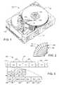
- FIG. 1is an isometric view of a disc drive data storage device in which embodiments of the present invention can be practiced.
- FIG. 2is a diagrammatic depiction of the servo and data wedges into which data is stored in the data storage medium of the disc drive of FIG. 1 .
- FIG. 3is a diagrammatic depiction of the data fields in the servo and data wedges of FIG. 2 .
- FIGS. 4 and 5are isometric views of a servo track writer (“STW”) of the type that can be used to pre-format servo patterns on the data storage medium of the disc drive of FIG. 1 .
- STWservo track writer
- FIG. 6is a block diagram of a data transfer member control circuit in a verification device.
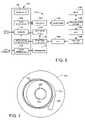
- FIG. 7is a diagrammatic depiction of the eccentricity condition arising from repositioning the discs between servo formatting and media certification.
- FIG. 8is a diagrammatic depiction of the head in the R write position.
- FIG. 9is a diagrammatic depiction of the head in the R cert position.
- FIG. 10is a block diagram of steps for practicing a method for MEDIA CERTIFICATION in accordance with embodiments of the present invention.
- FIG. 1is an isometric view of an illustrative data storage device 100 suited for use with and for practicing embodiments of the present invention.
- a plurality data storage discs 102are rotated by a motor 104 to present data storage locations of the disc 102 to a read/write head (“head”) 106 .
- the head 106is supported at the distal end of a rotary actuator 108 that is capable of moving the head 106 radially between inner and outer data storage tracks of the disc 102 .
- the head 106is electrically connected to a circuit board 110 by way of a flex circuit 112 .
- the circuit board 110is adapted to receive and send control signals controlling the functions of the data storage device 100 .
- a connector 114is electrically connected to the circuit board 110 , and is adapted for connecting the data storage device 100 with remote devices for transferring commands and/or data.
- FIGS. 2 and 3illustrate a manner in which data can be arranged on each of the recording surfaces of the discs 102 .
- Servo data wedges 116are written during disc drive manufacturing and radially extend across the recording surfaces like spokes on a wheel.
- Each servo wedge 116is formed from a number of servo data fields 118 for each servo data track 120 .
- the servo dataare used to detect and control the position of the heads 106 .
- Data wedges 122are provided between each adjacent pair of servo wedges 116 .
- User data fields 124are subsequently defined in the data wedges 122 and are used to store user data in fixed size data blocks.
- data trackor “track” means a track in which data is stored, whether it be servo data or user data or both.
- servo data trackmeans a track formed by a plurality of servo data, with or without user data stored therein.
- Each servo data field 118includes an automatic gain control (AGC) field 126 , a synchronization field 128 , an index field 130 , a Gray code (track address) field 132 , and a position (POS) field 134 .
- the AGC field 126provides an oscillating preamble signal (such as a 2T pattern) to prepare servo control circuitry for receipt of the remaining servo data.
- the synchronization field 128signals the presence of a servo data field 118 by storing a unique synchronization pattern that is a selected Hamming distance away from other possible combinations of bit patterns on the disc 102 .
- the index field 130indicates angular position of the servo data field 118 on the disc 102 with respect to an index point (i.e., zero rotational degrees).
- the Gray code field 132provides a radial track address for the track 120 , and the position field 134 enables the servo control circuitry to detect intra-track location of the head 106 .
- the user data fields 124 labeled D 0 , D 1 , and D 2are contiguous data fields and each include an AGC field 136 , a synchronization field 138 , a user data field 140 , an error correction code (ECC) field 142 in which error detection and correction codes are stored, a pad field 144 and an intersector gap 146 .
- ECCerror correction code
- the servo wedges 116(“bursts”) are written to the disc 102 .
- the servo wedges 116are then used to propagate readback data 122 for the purpose of certifying that the requisite quality exists in the magnetizable medium.
- both the servo data fields 118 and the readback data 124are written by the heads 106 after the discs 102 have been installed in the data storage device 100 .
- this type of “in-situ” data transferhas more recently been replaced by pre-formatting the discs 102 with servo wedges 116 , such as by using a dedicated STW device.
- the pre-formatted discs 102can then be subjected to a media certification procedure by repositioning them in another dedicated device known generally as a pattern verifier, including the data storage device 100 itself, in order to observe an error rate associated with writing data and then reading it back (“readback data”).
- a pattern verifierincluding the data storage device 100 itself
- readback dataan error rate associated with writing data and then reading it back
- Batch-production of the pre-formatted discs 102has demonstrated proven advantages in manufacturing throughput velocity. However, it also can be problematic from the standpoint that repositioning the discs 102 will likely create eccentricity issues.
- FIGS. 4 and 5illustrate a dedicated multi-disc STW 150 for the accurate positioning and movement of servo recording heads during servo pattern recording on a disc, and is the subject of U.S. Pat. No. 6,775,088 that is assigned to the assignee of the present application.
- the STW 150includes an actuator assembly 152 for providing rotating servo recording heads 154 necessary for recording servo patterns onto a target disc 102 .
- a plurality of discs 102are mounted onto a mandrel 155 and grippingly engaged at one end thereof by a spindle motor hub assembly 156 .
- the spindle motor hub assembly 156positions the target discs 102 in relation to the servo recording heads 154 .
- a vacuum chuck 158rigidly secures the actuator assembly 152 in a desired position for servo track writing.
- a laser interferometermeasures the angular displacement and consequent positioning of the servo-recording heads 154 .
- the entire multi-disc servo writer 150sits upon a substantially immobile and horizontally positioned platform or base 162 .
- the platform 162is substantially resistant to movements from impact type collisions, and is preferably a granite slab or other like material having sufficient size to support all the components of the STW 150 .
- the actuator assembly 152is connected to the platform 162 via a slide mechanism 164 for lateral movement (as indicated by arrow 166 ) over the platform 162 between a servo recording position (shown in FIG. 5 ) and a disc loading and unloading position (shown in FIG. 4 )
- the discs 102are removed from the mandrel 155 and mounted to another device for performing the media certification (“verifier” device).
- the verifier devicecan be the data storage device 100 , wherein the discs 102 are repositioned and mounted to the spindle motor 104 .
- the verifier devicecan be a dedicated piece of production equipment, and that the features and control circuitry ascribed to the data storage device 100 for purposes of practicing the present embodiments can equivalently be ascribed to any such dedicated production device.
- FIG. 6provides a functional block diagram of relevant circuitry of the verifier device including an interface circuit 170 , processor 172 and read/write channel 174 .
- the interface circuit 170communicates with a host device in accordance with an industry standard protocol, such as Small Computer Systems Interface (SCSI).
- the processor 172provides top level control of the verifier device.
- the read/write channel 174operates to write data to the discs 102 and to retrieve readback data from the discs 102 .
- the read channel portion of the read/write channel 174is contemplated to use partial response, maximum likelihood (PRML) detection, although such is not limiting to the scope of the claimed invention.
- PRMLpartial response, maximum likelihood
- the hostprovides a write command to a host interface circuit 176 of the interface circuit 170 and loads the data to be written to a data buffer 178 .
- the dataare encoded by an encoder circuit 180 to provide run length limited (RLL) and error correction encoding, and the encoded data are serialized by a serializer 182 .
- the output of the serializer 182preferably constitutes a non-return to zero (NRZ) signal used by a preamplifier/driver circuit 184 (preamp) to apply bi-directional write currents to the data transfer head to write the data as a sequence of magnetic flux transitions on the disc recording surface.
- NRZnon-return to zero
- the dataare transduced from the disc surface by the head to provide a readback signal that is preamplified by the preamp 184 , normalized by an AGC circuit 186 and filtered by an adaptive filter 188 .
- the filtered signalundergoes time-domain filtering to a selected class of partial response waveforms (e.g., EPR4) by a finite response filter (FIR) 190 .
- a sequence (Viterbi) detector 192samples the output of the FIR 190 to provide a sequence of data values representative of the encoded data written to the disc 102 .
- a decoder 194removes the RLL encoding and applies on-the-fly error detection and correction to provide the recovered user data to the buffer 178 for subsequent transfer to the host device.
- a sequencer 196asserts read and write gate signals to control the writing and reading of data by the read/write channel 174 .
- the interface circuit 170further comprises a data generator 198 which generates a 2T oscillating pattern for use at selected times including during the media certification operation during disc drive assembly operations. During media certification, the 2T pattern can be written to each data wedge 122 .
- FIG. 7is provided to illustrate how this eccentricity comes into play, but it is noted that the extent of the eccentricity and the clearances in FIG. 7 are visually exaggerated for clarity sake.
- FIG. 7illustrates a pre-formatted disc 102 ; that is, the disc 102 has previously been mounted on the mandrel 155 of the STW 150 in order write servo wedges 116 along a plurality of tracks (illustrated by three tracks) 120 .
- the disc 102is shown now mounted to the spindle motor 104 of the data storage device (in this case the “verifier”) of FIG. 1 .
- the disc 102 inner edge 200defines a diameter that is larger than the hub of the spindle motor 104 , thereby providing sliding clearance for mounting the discs 102 on the hub. However, this lateral clearance results in the disc center being offset from the axis of rotation.
- the tracks 120 of previously written servo wedges 122are eccentric in relation to the axis of the verifier. That is, the tracks 120 are concentric in relation to each other, but are non-concentric in relation to the axis of rotation in the verifier. Furthermore, a path of travel 202 for the verifier data transfer member (in this case head 106 ) when it is in a fixed radial position, is eccentric (or “non-concentric) in relation to the disc 102 center. However, the head path of travel 202 is concentric to the disc axis of rotation.
- Previous attempted solutionsaim to conform the head path of travel 202 to one of the eccentric servo data tracks 120 . That is, track-following a selected one of the tracks 120 for media certification can be attempted by compensating the head position in relation to a position error signal (PES).
- PESposition error signal
- the present embodimentstake a better tact of keeping the head substantially fixed radially. As the diagram of FIG. 7 indicates, this results in the head and its associated control circuit (“data transfer member control circuit” or “head control circuit”) retrieving readback data from different data storage tracks during less than one revolution of the disc. In other words, the present embodiments contemplate that the head control circuit will likely retrieve a first readback data block 140 that is associated with a first data storage track 120 , and will likely retrieve a consecutive second readback data block 140 that is associated with a second data storage track 120 different than the first data storage track 120 .
- the fixed-head path 202is shown to cross only a portion of the data tracks 120 .
- the fixed-head path 202is disposed entirely across a plurality of the data tracks 120 .
- FIG. 8diagrammatically depicts the head 106 having a reader element 210 and a writer element 212 that are spatially separated by an offset distance 213 (R/W offset).
- the verifier of the present embodimentswrites a certifiable data pattern by first reading and storing a radial location R write 214 before writing data block 216 . The verifier then reads and stores R write 218 before writing data block 220 . This sequence of storing R write before writing each of the data blocks continues until a predetermined amount of data has been written.
- FIG. 9diagrammatically depicts the head 106 having been moved to certifying mode whereby the readback data is scrutinized for signs of media defects, such as the two defects shown in the previously written data.
- the head control circuit of the verifierassociates each readback data block with one of the data storage tracks, in relation to a preceding servo burst 118 . For example, the head control circuit determines that its R cert position 221 is nearest the servo burst 118 of track 10 , 045 and thereby associates readback data block 222 with that track. Similarly, the head control circuit determines that a subsequent R cert position 223 is nearest the servo burst 118 of track 10 , 046 and thereby associates readback data block 224 with that track. The defects indicated by read errors in these data blocks 222 , 224 are then mapped in relation to the tracks with which they have been associated.
- FIG. 10is a flowchart showing steps for practicing a method 230 of MEDIA CERTIFICATION in accordance with embodiments of the present invention.
- the methodbegins in block 232 with mounting the discs 106 in the STW 150 .
- Servo informationis then written to the discs 106 in block 234 , and then the discs are removed from the STW in block 236 .
- the discs 106are repositioned and mounted to the verifier, and in block 240 the head control circuit moves the head to a fixed radial position for writing a certifiable pattern of data.
- writeiis stored in memory prior to writing data i in block 244 .
- block 246it is determined whether all the readback data has been written. If no, then control returns to the sequence of blocks 242 , 244 ; otherwise control passes to block 248 .
- the head control circuitmoves the head to R cert , as defined above, for retrieving readback data with the head along a path that is non-concentric in relation to the pre-formatted servo data tracks 120 .
- R cert radial positionis seamlessly compared to the adjacent pair of servo bursts, between which it is interposed, in order to ascertain which is closest. Based on that finding, in block 252 the nearest servo burst defines the track with which the subsequent readback data block will be associated.
- the immediately next readback data blockis read. It is determined in block 256 whether any readback error indicates the likelihood that a defect exists in the magnetizable medium. If yes, then in block 258 the location of the defect is associated with the track designation determined in block 252 . Otherwise, in block 260 it is determined whether all the readback data have been read. If no, then control returns to block 248 ; otherwise, the defects are mapped in block 262 according to the track associations determined in block 258 .
- the present embodimentscontemplate a media certifier having a data transfer member operably disposable in a data transfer relationship with a pre-formatted media, and means for certifying the media without track-following the pre-formatted media.
- the term “means for certifying”encompasses the present embodiments that require the verifier head to be moved substantially in a concentric path to the disc axis of rotation, and in relation to eccentric pre-formatted tracks of servo information.
- the term “means for certifying”expressly does not encompass other solutions whereby the verifier head position is compensated in relation to an observed position error, thereby track-following one or more of the eccentric pre-formatted servo tracks.
Landscapes
- Signal Processing For Digital Recording And Reproducing (AREA)
Abstract
Description
Rcert=Rwrite+R/Woffset
Claims (20)
Priority Applications (1)
| Application Number | Priority Date | Filing Date | Title |
|---|---|---|---|
| US11/506,934US7349172B2 (en) | 2006-08-18 | 2006-08-18 | Certifying concentric data in eccentric servo data tracks of pre-formatted media |
Applications Claiming Priority (1)
| Application Number | Priority Date | Filing Date | Title |
|---|---|---|---|
| US11/506,934US7349172B2 (en) | 2006-08-18 | 2006-08-18 | Certifying concentric data in eccentric servo data tracks of pre-formatted media |
Publications (2)
| Publication Number | Publication Date |
|---|---|
| US20080043362A1 US20080043362A1 (en) | 2008-02-21 |
| US7349172B2true US7349172B2 (en) | 2008-03-25 |
Family
ID=39101143
Family Applications (1)
| Application Number | Title | Priority Date | Filing Date |
|---|---|---|---|
| US11/506,934Expired - Fee RelatedUS7349172B2 (en) | 2006-08-18 | 2006-08-18 | Certifying concentric data in eccentric servo data tracks of pre-formatted media |
Country Status (1)
| Country | Link |
|---|---|
| US (1) | US7349172B2 (en) |
Cited By (2)
| Publication number | Priority date | Publication date | Assignee | Title |
|---|---|---|---|---|
| US20080111553A1 (en)* | 2005-02-16 | 2008-05-15 | Butch Mulcahey | Digital locating system and device for underground object detection |
| US20080239540A1 (en)* | 2007-03-30 | 2008-10-02 | Seagate Technology Llc | Media servowriter/certifier |
Families Citing this family (2)
| Publication number | Priority date | Publication date | Assignee | Title |
|---|---|---|---|---|
| US20100195469A1 (en)* | 2009-02-02 | 2010-08-05 | Doug Carson & Associates, Inc. | Media Pre-Write With Track-Aligned Write Beam Deflection and Write Frequency Adjustment |
| US8792201B2 (en)* | 2009-12-02 | 2014-07-29 | Seagate Technology Llc | Method of disc alignment using printed alignment marks |
Citations (10)
| Publication number | Priority date | Publication date | Assignee | Title |
|---|---|---|---|---|
| US5822773A (en)* | 1996-10-17 | 1998-10-13 | Fwb Software Llc | Method and system for accelerating the copying of repetitively copied computer data |
| US6411452B1 (en)* | 1997-03-11 | 2002-06-25 | Western Digital Technologies, Inc. | Disk drive employing read error tolerant sync mark detection |
| US20020145966A1 (en)* | 2001-04-06 | 2002-10-10 | Akeimi Hirotsune | Information recording medium |
| US20030147171A1 (en) | 2002-02-05 | 2003-08-07 | Xinwei Li | Method for measuring PES noise of servo patterned media |
| US20040145825A1 (en)* | 2003-01-24 | 2004-07-29 | Xyratex Technology Limited | Methods and apparatus for writing servo frames to and/or verifying data areas of a storage medium |
| US6839763B1 (en)* | 2001-02-28 | 2005-01-04 | Emc Corporation | System and method for expediting transfer of data from a local storage facility to a remote storage facility |
| US20050063086A1 (en) | 2003-09-23 | 2005-03-24 | Justin Won | Interleaved repeatable runout estimation |
| US6898033B2 (en)* | 2001-10-05 | 2005-05-24 | Seagate Technology Llc | Anticipating media decay in a disc drive |
| US6947232B2 (en) | 2001-04-26 | 2005-09-20 | Seagate Technology Llc | User data wedge media certification apparatus and method |
| US7035039B2 (en)* | 2002-01-08 | 2006-04-25 | Hitachi Electronics Engineering Co., Ltd. | Magnetic head positioning control device, magnetic head certifier, magnetic disk certifier and head cartridge |
- 2006
- 2006-08-18USUS11/506,934patent/US7349172B2/ennot_activeExpired - Fee Related
Patent Citations (11)
| Publication number | Priority date | Publication date | Assignee | Title |
|---|---|---|---|---|
| US5822773A (en)* | 1996-10-17 | 1998-10-13 | Fwb Software Llc | Method and system for accelerating the copying of repetitively copied computer data |
| US6411452B1 (en)* | 1997-03-11 | 2002-06-25 | Western Digital Technologies, Inc. | Disk drive employing read error tolerant sync mark detection |
| US6441981B1 (en)* | 1997-03-11 | 2002-08-27 | Western Digital Technologies, Inc. | Disk drive including a recording surface employing servo zones recorded at a channel frequency different from data zones |
| US6839763B1 (en)* | 2001-02-28 | 2005-01-04 | Emc Corporation | System and method for expediting transfer of data from a local storage facility to a remote storage facility |
| US20020145966A1 (en)* | 2001-04-06 | 2002-10-10 | Akeimi Hirotsune | Information recording medium |
| US6947232B2 (en) | 2001-04-26 | 2005-09-20 | Seagate Technology Llc | User data wedge media certification apparatus and method |
| US6898033B2 (en)* | 2001-10-05 | 2005-05-24 | Seagate Technology Llc | Anticipating media decay in a disc drive |
| US7035039B2 (en)* | 2002-01-08 | 2006-04-25 | Hitachi Electronics Engineering Co., Ltd. | Magnetic head positioning control device, magnetic head certifier, magnetic disk certifier and head cartridge |
| US20030147171A1 (en) | 2002-02-05 | 2003-08-07 | Xinwei Li | Method for measuring PES noise of servo patterned media |
| US20040145825A1 (en)* | 2003-01-24 | 2004-07-29 | Xyratex Technology Limited | Methods and apparatus for writing servo frames to and/or verifying data areas of a storage medium |
| US20050063086A1 (en) | 2003-09-23 | 2005-03-24 | Justin Won | Interleaved repeatable runout estimation |
Cited By (4)
| Publication number | Priority date | Publication date | Assignee | Title |
|---|---|---|---|---|
| US20080111553A1 (en)* | 2005-02-16 | 2008-05-15 | Butch Mulcahey | Digital locating system and device for underground object detection |
| US20080239540A1 (en)* | 2007-03-30 | 2008-10-02 | Seagate Technology Llc | Media servowriter/certifier |
| US7768736B2 (en) | 2007-03-30 | 2010-08-03 | Seagate Technology Llc | Certifying while servowriting media |
| US7880987B2 (en) | 2007-03-30 | 2011-02-01 | Seagate Technology Llc | Media servowriter/certifier |
Also Published As
| Publication number | Publication date |
|---|---|
| US20080043362A1 (en) | 2008-02-21 |
Similar Documents
| Publication | Publication Date | Title |
|---|---|---|
| US6738215B2 (en) | Method and system for accurate self-servo writing by using relative position between head and writing surface | |
| US6754030B2 (en) | Optimal reader-to-writer offset measurement of a head in a disc drive for reduced track misregistration | |
| US7595955B2 (en) | Disk drive device and method for error recovery procedure therefor | |
| US6963458B2 (en) | Method and apparatus for reducing the servo position error signal non-linearity during self-servo writing irrespective of the head width | |
| US6798594B2 (en) | Position sensing system for a disc drive using micro-servo sectors and side-by-side R/W recording elements | |
| US5963387A (en) | Method for forming and processing data address mark for hard disk drive | |
| US20080002279A1 (en) | Method and apparatus for writing a spiral servo pattern on a disk in a disk drive | |
| US7511912B2 (en) | Writing multiple servo sector patterns to improve servo sector alignment on multiple surfaces | |
| US7715140B2 (en) | Method of determining size of error and write control method for hard disc drive, hard disc drive using the write control method, and media storing computer programs for executing the methods | |
| JP3123710B2 (en) | Disk device, track positioning method, and position error signal generation method | |
| US7349172B2 (en) | Certifying concentric data in eccentric servo data tracks of pre-formatted media | |
| US7764455B2 (en) | Method and apparatus for detecting defects of servo data in a disk drive | |
| JP2006012353A (en) | Disk device and manufacturing method thereof | |
| US7538965B2 (en) | Method and apparatus for writing servo management information in a disk drive | |
| JP2011129230A (en) | Disk storage device and data recording/reproducing method | |
| KR100712503B1 (en) | Servo data creation method of hard disk drive and self-servo recording method using the same | |
| KR100688506B1 (en) | Self-servo recording method, a suitable hard disk drive, and recording medium | |
| US12211529B1 (en) | Fast characterization of media-noise-induced repeatable runout | |
| KR100712513B1 (en) | Hard disk drive recording control method, and suitable hard disk drive and recording media | |
| KR100640606B1 (en) | Servo information inspection method of hard disk drive and suitable recording medium | |
| US7154688B2 (en) | Disk device having a function to confirm that a selected head is proper for a disk surface | |
| KR100688508B1 (en) | Reference servo information recording method of hard disk drive, final servo information recording method, suitable hard disk drive, and recording medium | |
| JP2007220204A (en) | Test method for disk drive device | |
| KR20060136255A (en) | Recording controll method of harddisk drive and harddisk drive and recording medium for the same | |
| US20110249358A1 (en) | Apparatus and method of detecting a defective sector in a disk drive |
Legal Events
| Date | Code | Title | Description |
|---|---|---|---|
| AS | Assignment | Owner name:SEAGATE TECHNOLOGY LLC, CALIFORNIA Free format text:ASSIGNMENT OF ASSIGNORS INTEREST;ASSIGNOR:MCLERAN, DAN R.;REEL/FRAME:018198/0665 Effective date:20060818 | |
| STCF | Information on status: patent grant | Free format text:PATENTED CASE | |
| AS | Assignment | Owner name:WELLS FARGO BANK, NATIONAL ASSOCIATION, AS COLLATERAL AGENT AND SECOND PRIORITY REPRESENTATIVE, CALIFORNIA Free format text:SECURITY AGREEMENT;ASSIGNORS:MAXTOR CORPORATION;SEAGATE TECHNOLOGY LLC;SEAGATE TECHNOLOGY INTERNATIONAL;REEL/FRAME:022757/0017 Effective date:20090507 Owner name:JPMORGAN CHASE BANK, N.A., AS ADMINISTRATIVE AGENT AND FIRST PRIORITY REPRESENTATIVE, NEW YORK Free format text:SECURITY AGREEMENT;ASSIGNORS:MAXTOR CORPORATION;SEAGATE TECHNOLOGY LLC;SEAGATE TECHNOLOGY INTERNATIONAL;REEL/FRAME:022757/0017 Effective date:20090507 Owner name:JPMORGAN CHASE BANK, N.A., AS ADMINISTRATIVE AGENT Free format text:SECURITY AGREEMENT;ASSIGNORS:MAXTOR CORPORATION;SEAGATE TECHNOLOGY LLC;SEAGATE TECHNOLOGY INTERNATIONAL;REEL/FRAME:022757/0017 Effective date:20090507 Owner name:WELLS FARGO BANK, NATIONAL ASSOCIATION, AS COLLATE Free format text:SECURITY AGREEMENT;ASSIGNORS:MAXTOR CORPORATION;SEAGATE TECHNOLOGY LLC;SEAGATE TECHNOLOGY INTERNATIONAL;REEL/FRAME:022757/0017 Effective date:20090507 | |
| AS | Assignment | Owner name:SEAGATE TECHNOLOGY LLC, CALIFORNIA Free format text:RELEASE;ASSIGNOR:JPMORGAN CHASE BANK, N.A., AS ADMINISTRATIVE AGENT;REEL/FRAME:025662/0001 Effective date:20110114 Owner name:MAXTOR CORPORATION, CALIFORNIA Free format text:RELEASE;ASSIGNOR:JPMORGAN CHASE BANK, N.A., AS ADMINISTRATIVE AGENT;REEL/FRAME:025662/0001 Effective date:20110114 Owner name:SEAGATE TECHNOLOGY HDD HOLDINGS, CALIFORNIA Free format text:RELEASE;ASSIGNOR:JPMORGAN CHASE BANK, N.A., AS ADMINISTRATIVE AGENT;REEL/FRAME:025662/0001 Effective date:20110114 Owner name:SEAGATE TECHNOLOGY INTERNATIONAL, CALIFORNIA Free format text:RELEASE;ASSIGNOR:JPMORGAN CHASE BANK, N.A., AS ADMINISTRATIVE AGENT;REEL/FRAME:025662/0001 Effective date:20110114 | |
| AS | Assignment | Owner name:THE BANK OF NOVA SCOTIA, AS ADMINISTRATIVE AGENT, CANADA Free format text:SECURITY AGREEMENT;ASSIGNOR:SEAGATE TECHNOLOGY LLC;REEL/FRAME:026010/0350 Effective date:20110118 Owner name:THE BANK OF NOVA SCOTIA, AS ADMINISTRATIVE AGENT, Free format text:SECURITY AGREEMENT;ASSIGNOR:SEAGATE TECHNOLOGY LLC;REEL/FRAME:026010/0350 Effective date:20110118 | |
| FPAY | Fee payment | Year of fee payment:4 | |
| AS | Assignment | Owner name:SEAGATE TECHNOLOGY US HOLDINGS, INC., CALIFORNIA Free format text:TERMINATION AND RELEASE OF SECURITY INTEREST IN PATENT RIGHTS;ASSIGNOR:WELLS FARGO BANK, NATIONAL ASSOCIATION, AS COLLATERAL AGENT AND SECOND PRIORITY REPRESENTATIVE;REEL/FRAME:030833/0001 Effective date:20130312 Owner name:SEAGATE TECHNOLOGY LLC, CALIFORNIA Free format text:TERMINATION AND RELEASE OF SECURITY INTEREST IN PATENT RIGHTS;ASSIGNOR:WELLS FARGO BANK, NATIONAL ASSOCIATION, AS COLLATERAL AGENT AND SECOND PRIORITY REPRESENTATIVE;REEL/FRAME:030833/0001 Effective date:20130312 Owner name:EVAULT INC. (F/K/A I365 INC.), CALIFORNIA Free format text:TERMINATION AND RELEASE OF SECURITY INTEREST IN PATENT RIGHTS;ASSIGNOR:WELLS FARGO BANK, NATIONAL ASSOCIATION, AS COLLATERAL AGENT AND SECOND PRIORITY REPRESENTATIVE;REEL/FRAME:030833/0001 Effective date:20130312 Owner name:SEAGATE TECHNOLOGY INTERNATIONAL, CAYMAN ISLANDS Free format text:TERMINATION AND RELEASE OF SECURITY INTEREST IN PATENT RIGHTS;ASSIGNOR:WELLS FARGO BANK, NATIONAL ASSOCIATION, AS COLLATERAL AGENT AND SECOND PRIORITY REPRESENTATIVE;REEL/FRAME:030833/0001 Effective date:20130312 | |
| FPAY | Fee payment | Year of fee payment:8 | |
| FEPP | Fee payment procedure | Free format text:MAINTENANCE FEE REMINDER MAILED (ORIGINAL EVENT CODE: REM.); ENTITY STATUS OF PATENT OWNER: LARGE ENTITY | |
| LAPS | Lapse for failure to pay maintenance fees | Free format text:PATENT EXPIRED FOR FAILURE TO PAY MAINTENANCE FEES (ORIGINAL EVENT CODE: EXP.); ENTITY STATUS OF PATENT OWNER: LARGE ENTITY | |
| STCH | Information on status: patent discontinuation | Free format text:PATENT EXPIRED DUE TO NONPAYMENT OF MAINTENANCE FEES UNDER 37 CFR 1.362 | |
| FP | Lapsed due to failure to pay maintenance fee | Effective date:20200325 | |
| AS | Assignment | Owner name:SEAGATE TECHNOLOGY PUBLIC LIMITED COMPANY, CALIFORNIA Free format text:RELEASE BY SECURED PARTY;ASSIGNOR:THE BANK OF NOVA SCOTIA;REEL/FRAME:072193/0001 Effective date:20250303 Owner name:SEAGATE TECHNOLOGY, CALIFORNIA Free format text:RELEASE BY SECURED PARTY;ASSIGNOR:THE BANK OF NOVA SCOTIA;REEL/FRAME:072193/0001 Effective date:20250303 Owner name:SEAGATE TECHNOLOGY HDD HOLDINGS, CALIFORNIA Free format text:RELEASE BY SECURED PARTY;ASSIGNOR:THE BANK OF NOVA SCOTIA;REEL/FRAME:072193/0001 Effective date:20250303 Owner name:I365 INC., CALIFORNIA Free format text:RELEASE BY SECURED PARTY;ASSIGNOR:THE BANK OF NOVA SCOTIA;REEL/FRAME:072193/0001 Effective date:20250303 Owner name:SEAGATE TECHNOLOGY LLC, CALIFORNIA Free format text:RELEASE BY SECURED PARTY;ASSIGNOR:THE BANK OF NOVA SCOTIA;REEL/FRAME:072193/0001 Effective date:20250303 Owner name:SEAGATE TECHNOLOGY INTERNATIONAL, CAYMAN ISLANDS Free format text:RELEASE BY SECURED PARTY;ASSIGNOR:THE BANK OF NOVA SCOTIA;REEL/FRAME:072193/0001 Effective date:20250303 Owner name:SEAGATE HDD CAYMAN, CAYMAN ISLANDS Free format text:RELEASE BY SECURED PARTY;ASSIGNOR:THE BANK OF NOVA SCOTIA;REEL/FRAME:072193/0001 Effective date:20250303 Owner name:SEAGATE TECHNOLOGY (US) HOLDINGS, INC., CALIFORNIA Free format text:RELEASE BY SECURED PARTY;ASSIGNOR:THE BANK OF NOVA SCOTIA;REEL/FRAME:072193/0001 Effective date:20250303 |